

Page 1

911
CNC-controlled sewing unit with large
sewing area
Operating Instructions
Installation Instructions
Service Instructions
Postfach 17 03 51, D-33703 Bielefeld Potsdamer Straße 190, D-33719 Bielefeld
Telefon +49 (0) 5 21/ 59 25-00 Telefax +49 (0) 5 21/ 9 25 24 35 www.duerkopp-adler.com
1
2
Ausgabe / Edition: Änderungsindex Teile-Nr./Part.-No.:
08/2010 Rev. index: 00.0 Printed in Federal Republic of Germany 0791 911001
3
Page 2

All rights reserved.
Property of Dürkopp Adler AG and copyrighted. Reproduction or publication of the content in any
manner, even in extracts, without prior written permission of Dürkopp Adler AG, is prohibited.
Copyright ©
Dürkopp Adler AG - 2010
Page 3

Foreword
This instruction manual is intended to help the user to become familiar
with the machine and take advantage of its application possibilities in
accordance with the recommendations.
The instruction manual contains important information on how to
operate the machine securely, properly and economically. Observation
of the instructions eliminates danger, reduces costs for repair and
down-times, and increases the reliability and life of the machine.
The instruction manual is intended to complement existing national
accident prevention and environment protection regulations.
The instruction manual must always be available at the machine/sewing
unit.
The instruction manual must be read and applied by any person that is
authorized to work on the machine/sewing unit. This means:
– Operation, including equipping, troubleshooting during the work
cycle, removing of fabric waste,
– Service (maintenance, inspection, repair) and/or
– Transport.
The user also has to assure that only authorized personnel work on the
machine.
The user is obliged to check the machine at least once per shift for
apparent damages and to immediatly report any changes (including the
performance in service), which impair the safety.
The user company must ensure that the machine is only operated in
perfect working order.
Never remove or disable any safety devices.
If safety devices need to be removed for equipping, repairing or
maintaining, the safety devices must be remounted directly after
completion of the maintenance and repair work.
Unauthorized modification of the machine rules out liability of the
manufacturer for damage resulting from this.
Observe all safety and danger recommendations on the machine/unit!
The yellow-and-black striped surfaces designate permanend danger
areas, eg danger of squashing, cutting, shearing or collision.
Besides the recommendations in this instruction manual also observe
the general safety and accident prevention regulations!
Page 4

General safety instructions
The non-observance of the following safety instructions can cause
bodily injuries or damages to the machine.
1. The machine must only be commissioned in full knowledge of the
instruction book and operated by persons with appropriate training.
2. Before putting into service also read the safety rules and
instructions of the motor supplier.
3. The machine must be used only for the purpose intended. Use of
the machine without the safety devices is not permitted. Observe all
the relevant safety regulations.
4. When gauge parts are exchanged (e.g. needle, presser foot, needle
plate, feed dog and bobbin) when threading, when the workplace is
left, and during service work, the machine must be disconnected
from the mains by switching off the master switch or disconnecting
the mains plug.
5. Daily servicing work must be carried out only by appropriately
trained persons.
6. Repairs, conversion and special maintenance work must only be
carried out by technicians or persons with appropriate training.
7. For service or repair work on pneumatic systems, disconnect the
machine from the compressed air supply system (max. 7-10 bar).
Before disconnecting, reduce the pressure of the maintenance unit.
Exceptions to this are only adjustments and functions checks made
by appropriately trained technicians.
8. Work on the electrical equipment must be carried out only by
electricians or appropriately trained persons.
9. Work on parts and systems under electric current is not permitted,
except as specified in regulations DIN VDE 0105.
10. Conversion or changes to the machine must be authorized by us
and made only in adherence to all safety regulations.
11. For repairs, only replacement parts approved by us must be used.
12. Commissioning of the sewing head is prohibited until such time as
the entire sewing unit is found to comply with EC directives.
13. The line cord should be equipped with a country-specific mains
plug. This work must be carried out by appropriately trained
technicians (see paragraph 8).
It is absolutely necessary to respect the safety
instructions marked by these signs.
Danger of bodily injuries !
Please note also the general safety instructions.
Page 5

Contents Page:
Part 2: Installation Instructions 911 – Original Instructions
1. Scope of delivery .............................................. 3
2. General .................................................... 3
3. Installing the sewing unit
3.1 Transport.................................................... 4
3.2 Removingthesecuritydevices ...................................... 5
3.3 Settingtheworkingheight......................................... 6
3.3.1 Sewingunitswithrollers .......................................... 6
3.3.2 Sewing units without rollers ........................................ 7
3.4 Fittingthefootpedal............................................. 8
4. Attaching the machine parts removed for shipping
4.1 Threadreelholder.............................................. 9
5. Electrical connection
5.1 Connectingtothemains .......................................... 10
5.2 Checking the nominal voltage ....................................... 10
5.3 Directionofrotationofthesewingmotor ................................ 10
6. Pneumatic connection .......................................... 11
7. Oil lubrication ................................................ 12
8. Putting into operation ........................................... 13
2
Page 6
2
1
2
4
3
Page 7

2
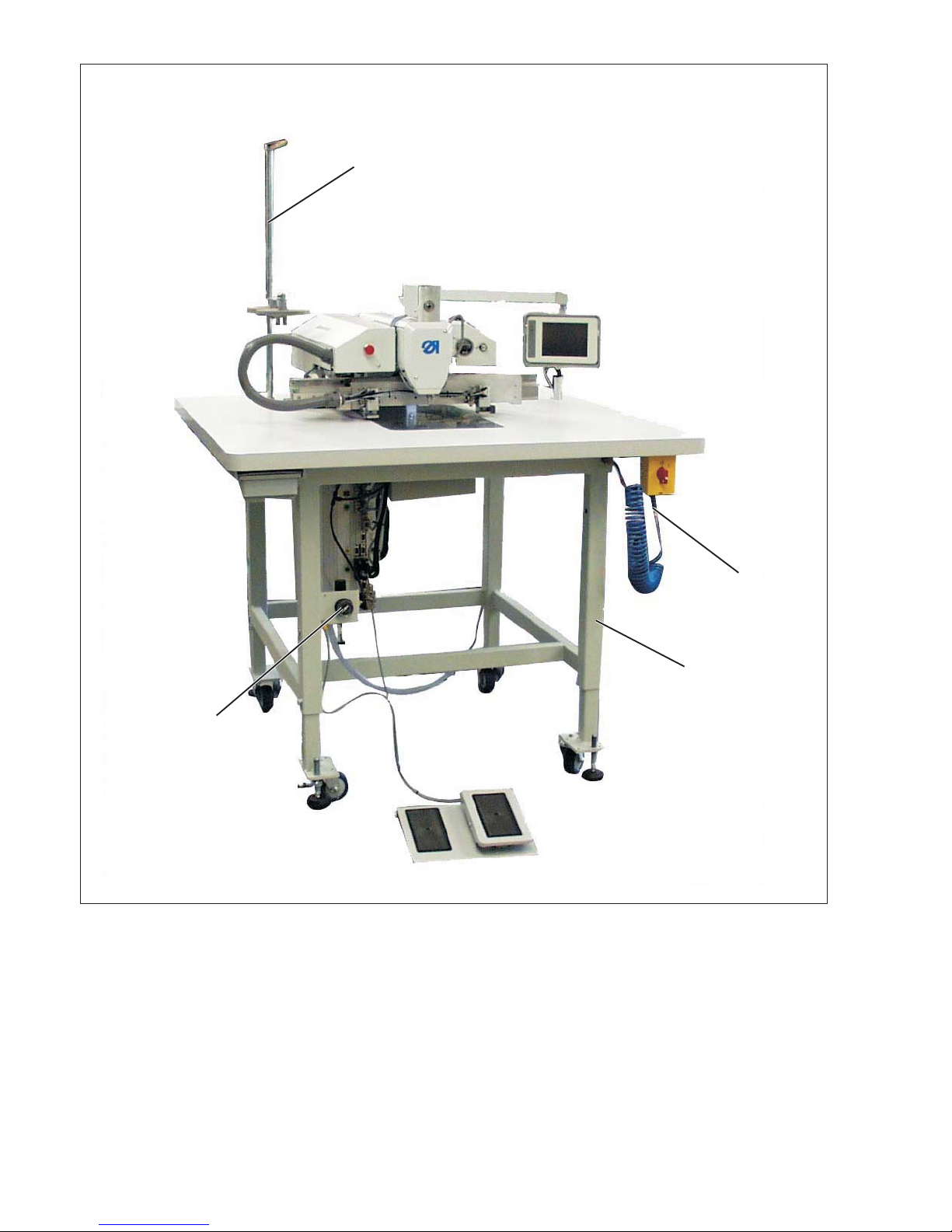
1. Scope of delivery
CNC-controlled sewing unit/pattern stitcher (max. sewing field
size 300 x 200 mm) based on the machine head class 867 and a
control unit DAC III with a special software.
Double-lockstitch machine equipped with: automatic sewing foot and
clamp lifting, sewing stroke adjustment.
Thread trimmer, needle thread monitoring, thread pulling device and
multiple thread tension device, made of the following:
–
3 Compressed air maintenance unit with compressed air gun 1
–
2 Stand (adjustable in height)
–
4 Thread stand
–
Tools and small parts in the accessories.
–
Additional equipment (optional)
2. General
ATTENTION!
The sewing unit must be set up by trained specialist personnel.
All work on the electrical equipment of this special sewing unit may
only be carried out by qualified electricians or other appropriately
trained persons.
The mains plug must be pulled out.
The enclosed operating instructions of the motor manufacturer have
to be observed without fail.
3
Page 8
4
3. Installing the sewing unit
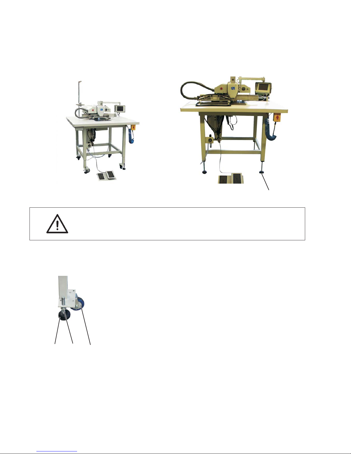
3.1 Transport
Transport the sewing unit using a lifting cart or a forklift, or its own
castors if available.
ATTENTION!
Before putting the sewing unit into operation, screw out the height
adjustable legs 1 until good stability is reached.
Lifting the sewing unit
–
Use only a lifting cart or a forklift.
Moving the sewing unit
–
In order to move the sewing unit via its own castors, loosen the
nuts 3 of the legs 1 and screw in the legs.
–
After the transport, screw out the legs 1 until the castors 2 lift off.
–
Fasten the nuts 3.
132
1
Page 9

3.2 Removing the security devices
Before installing the sewing unit all three securing devices have to be
remove d .
If the sewing unit has to be transported to another place, please
remount the securing devices again.
5
2
Page 10

3.3 Setting the working height
3.3.1 Sewing units with rollers
The working height can be set between 760 mm and 910 mm
(measured up to the upper edge of the table top).
Caution: Risk of injury!
Do not lift the sewing unit using the table top.
Put a lifting cart or a forklift underneath the sewing unit before
loosening the clamping screw.
Set the height of the sewing unit by equally pulling the tubular feet of
the stand.
–
Loosen screws 1 (8x).
–
Set the table top to the desired height to be level.
To avoid a tilting, pull out / push in the tubular feet equally on both
sides.
–
Fasten screws 1.
6
1
Page 11

3.3.2 Sewing units without rollers
The working height can be set between 760 mm and 910 mm
(measured up to the upper edge of the table top).
Caution: Risk of injury!
Do not lift the sewing unit using the table top.
Put a lifting cart or a forklift underneath the sewing unit before
loosening the clamping screw.
Set the height of the sewing unit by equally screwing out the feet of
the stand.
–
Loosen the nuts 2 (4x).
–
Turn the threaded rods 1 accordingly.
–
Fasten the nuts 2.
7
2
21
Page 12

3.4 Fitting the foot pedal
The foot pedal can be placed as needed before the s ewing unit.
8
1
Page 13

4. Attaching the machine parts removed for shipping
4.1 Thread stand
–
Insert the thread stand 1 in the drill-hole of the table top and
fasten it with nut 2 on top and nut 3 underneath the table top.
–
Mount and align the thread plate and the unwinding arms as
shown in the illustration.
2
9
21
3
Page 14
5. Electrical connection
ATTENTION!
All work on the electrical equipment of this sewing unit may only be
carried out by qualified electricians or other appropriately trained
persons.
The mains plug must be pulled out.
5.1 Connecting to the mains
–
Plug the mains cable into the socket.
230V -50/60 Hz
5.2 Checking the nominal voltage
ATTENTION!
The nominal voltage indicated at the type plate and the mains voltage
must correspond!
5.3 Direction of rotation of the sewing motor
The sewing unit is equipped with the newest step motor technology. It
is not necessary to check the direction of rotation, this being set
automatically by the control unit.
10
Page 15

2
6. Pneumatic connection
For the operation of pneumatic components, the sewing unit has to
be supplied with anhydrous compressed air.
ATTENTION!
For a trouble-free function of the pneumatic control procedures, the
compressed air supply must operate as follows:
Even at the moment of the highest air consumption, the minimum
operating pressure must not drop below 6bar.
In case of important drop of the air pressure:
–
Increase the compressor output.
–
Increase the diameter of the compressed air hose.
Connecting the maintenance unit f or compressed air
–
Connect the unit to the compressed-air supply with the
connection hose 3 (Order no. 0797 003031) and connector
R1/4".
Adjusting the operating pressure
–
The operating pressure is 6 bar.
It can be read off at the manometer 2.
–
To adjust the operating pressure raise and tur n handle 1.
–
Turn clockwise = increase pressure
–
Turn counter-clockwise = reduce pressure
ATTENTION!
No oil-bearing compressed air must be fed from the compressed air
line.
The cleaned compressed air after t he filter is used as blowing air for
cleaning machine parts and for blowing workpieces out.
Oil particles contained in the blowing air lead to malfunctions and
stains on the workpieces.
11
321
Page 16

7. Oil lubrication
Caution: Risk of injury!
Oil can cause skin rashes.
Avoid longer skin contact.
After contact wash yourself thoroughly.
ATTENTION!
The handling and disposal of mineral oils is subject to legal
regulations.
Deliver used oil to an authorized collecting station.
Protect your environment.
Be careful not to spill any oil.
For filling up the oil reservoirs use only DA 10 lubricating oil or an
equivalent oil with the following specifications:
–
Viscosity a t 40° C : 10 mm
2
/s
–
Ignition point : 150° C
DA 10 is available from DÜRKOPP ADLER AG retail outlets under the
following part numbers:
250 ml container: 9047 000011
1-litre container: 9047 000012
2-litre container: 9047 000013
5-litre container: 9047 000014
Oil reservoir for the lubrication of the machine head
–
Fill oil reservoir 1 with oil through the drill-hole 2 in the inspection
glass.
The oil level must be between the “Min” and “Max” markings.
12
1
Page 17

8. Putting into operation
A sewing test should be carried out when setting-up is complete.
–
Plug the mains cable into the socket.
Caution: Risk of injury!
Turn off the main switch.
The needle and hook threads may only be threaded with the sewing
unit switched off.
–
Threading the needle thread (see operating instructions
chapter 6.4).
–
Threading the hook thread (see operating
instructions chapter 6.7).
–
Turn on the main switch.
The control unit will be initialised.
–
Step the pedal forward.
The reference run begins.
The carriage moves to the reference point.
The reference run is necessary in order to define a starting
position for the transport carriage.
–
Through stepping the pedal forward, the various steps of the
feeding process are initiated one after the other and the sewing
process is started.
ATTENTION!
Please make sure that material is positioned under the transport
clamps at the sewing s tart.
Moving the transport carriage w ithout material will damage the
coating of the transport clamps.
–
For the selection of the sewing program and for further settings of
the control unit see chapter 7 of the operating instructions.
13
2
Page 18

Notes:
14
 Loading...