

Page 1

878-M PREMIUM
Operating Instructions
Page 2

Všechna práva vyhrazena.
Vlastnictví společnosti Dürkopp Adler AG a chráněno autorskými právy.
Jakákoliv reprodukce těchto obsahů, a to i formou výňatků, je bez
předchozího písemného souhlasu společnosti Dürkopp Adler AG zakázána.
Copyright © Dürkopp Adler AG - 2018
Page 3

Obsah
1 About these instructions.................................. ..................................5
1.1 Scope of the instructions.......................................................................5
1.2 Applicable documentation.....................................................................5
1.3 Damage during transport.......................................................................5
1.4 Limitation of liability...............................................................................5
1.5 Symbols used........................................................................................6
1.6 Figures ..................................................................................................6
2 Technical Specifications ....................................................................7
2.1 Characteristics.......................................................................................7
2.2 Declaration of Conformity......................................................................7
2.3 Proper use................. ...................................................................... ......8
2.4 Technical data.......................................................................................9
2.4.1 Data overview by subclasses................................................................9
2.4.2 Additional equipment...........................................................................10
3 Safety..................................................................................................13
3.1 Basic safety instructions......................................................................13
3.2 Signal words and symbols used in warnings.......................................15
4 Machine Description .........................................................................19
5 Operation ...........................................................................................21
5.1 Switching power supply on and off......................................................21
5.2 Inserting and replacing the needle......................................................22
5.3 Threading the needle thread .......................................... ... ..................25
5.3.1 Tension plate electromagnetic ............................................................25
5.3.2 Tension plate electronic ......................................................................27
5.3.3 Tension plate rotary.............................................................................30
5.4 Inserting and winding on the hook thread .............................. ... ... ... ....31
5.5 Replacing the hook thread bobbin.......................................................34
5.6 Thread tension ......................................................... ...........................36
5.6.1 Setting needle thread tension for el. magnetic tension plate...............36
5.6.2 Setting hook thread tension.................................................................39
5.7 Setting the thread regulator.................................................................40
5.8 Lifting and folding the top roller...........................................................41
5.9 Holding the top roller in the upper position..........................................42
5.10 Electronic knee lever............................................. ... ... ........................43
5.11 Quick functions on the keypad............................................................44
5.11.1 Activating function keys.......................................................................44
5.11.2 Assigning key functions to the favorite button.....................................46
5.12 Operating the controller.......................................................................46
5.13 Sewing.................................................................................................47
6 Maintenance.......................................................................................49
6.1 Cleaning work......................................................................................49
6.2 Checking the oil level ..........................................................................51
6.3 Customer service ................................................................................52
Operating Instructions 878-M PREMIUM Verze 02.0 - 02/2018 1
Page 4

Obsah
7 Setup ..................................................................................................53
7.1 Checking the scope of delivery ...........................................................53
7.2 Removing the transport locks..............................................................54
7.3 Assembling frame components...........................................................54
7.4 Completing the table top ........................................................ ... ..........55
7.5 Fastening the table top to the frame....................................................56
7.6 Setting the working height...................................................................57
7.7 Controller.............................................................................................58
7.7.1 Fitting the control unit..........................................................................58
7.7.2 Fitting the pedal and setpoint device...................................................59
7.8 Mounting the machine head................................................................60
7.9 Fitting the oil extraction line.................................................................61
7.10 Fitting the tilt sensor............................................................................61
7.11 Installing the knee switch ....................................................................62
7.12 Fitting the control panel.......................................................................63
7.13 Electrical connection ...........................................................................63
7.13.1 Checking the mains voltage................................................................64
7.13.2 Fitting and connecting the sewing lamp and sewing lamp transformer64
7.13.3 Establishing equipotential bonding......................................................66
7.13.4 Connecting the control unit..................................................................67
7.14 Lubrication...........................................................................................67
7.15 Sewing test..........................................................................................69
8 Settings via the software..................................................................71
8.1 OP3000 control panel..........................................................................71
8.2 Switching the sewing machine on.......................................................72
8.3 Controller operating modes.................................................................73
8.4 Manual mode.......................................................................................74
8.4.1 Quick access function (softkey menu) .................................................76
8.4.2 Menu for other settings........................................................................77
8.4.3 Sewing.................................................................................................79
8.5 Automatic mode ..................................................................................79
8.5.1 Before starting sewing......................................................................... 80
8.5.2 Sewing.................................................................................................81
8.5.3 Canceling the program........................................................................82
8.6 Programming/edit mode......................................................................82
8.6.1 Creating programs...............................................................................82
8.6.2 Creating a program by keyboard input ................................................85
8.6.3 Creating a program by teach-in...........................................................85
8.6.4 Editing programs.................................................................................86
8.6.5 Changing further parameters for the current section...........................87
8.6.6 Changing further parameters for the selected program ......................89
8.6.7 Copying the program...........................................................................90
8.6.8 Deleting a program.................... ... ..................................... ..................91
8.7 Simplified display menu.......................................................................92
2 Operating Instructions 878-M PREMIUM Verze 02.0 - 02/2018
Page 5

Obsah
9 Disposal .............................................................................................93
10 Appendix............................................................................................95
10.1 Table top drawing...................... ..................................... ... ..................95
10.2 Component layout on underside of table top.......................................97
10.3 Interconnection diagram......................................................................98
Operating Instructions 878-M PREMIUM Verze 02.0 - 02/2018 3
Page 6

Obsah
4 Operating Instructions 878-M PREMIUM Verze 02.0 - 02/2018
Page 7

About these instructions
1 About these instructions
1.1 Scope of the instructions
These instructions describe the intended use and the setup of the
special sewing machine 878-M PREMIUM. It applies to all submodels listed in chapter 2.4 Technical data.
1.2 Applicable documentation
The device contains built-in components from other manufacturers, e.g. drive motors. Each manufacturer has performed a hazard
assessment for these purchased parts and confirmed their design
compliance with applicable European and national regulations.
The proper use of these components is described in each manufacturer's instructions.
1.3 Damage during transport
Dürkopp Adler cannot be held liable for any damage during transport. Inspect the delivery immediately upon receiving it.
Report any damage to the last transport manager.
This applies even if the packaging is undamaged.
Leave machines, equipment and packaging material in the condition in which they were found when the damage was discovered.
This will ensure any claims against the transport company.
Report all other complaints to Dürkopp Adler immediately after
receiving the product.
1.4 Limitation of liability
All information in these operating instructions was compiled with
consideration to the state of the art, and applicable standards and
regulations.
The manufacturer accepts no liability for any damage due to:
• Failure to observe the information given in these instructions
• Improper use
• Unauthorized modifications to the machine
• Use of untrained personnel
• Breakage and damage during transport
• Use of unapproved replacement parts
Operating Instructions 878-M PREMIUM - 02.0 - 02/2018 5
Page 8

About these instructions
1.
2.
etc.
1.5 Symbols used
Proper setting
Indicates proper setting.
Malfunctions
Specifies the faults that can occur due to an incorrect setting.
Steps to be performed when operating the machine (sewing
and equipping)
Steps to be performed for service, maintenance, and
installation
Steps to be performed via the software control panel
The individual steps are numbered:
1. First step
2. Second step
The sequence of the steps must always be followed.
Result of performing an operation
Change to the machine or on the display
Important
Special attention must be paid to this point when performing a step.
Information
Additional information, e.g. on alternative operating options.
Sequence
Specifies the work to be performed before or after a setting.
References
Reference to another section in these instructions.
1.6 Figures
Depending on the submodel, the appearance of the machine
varies in the following items:
Length of the machine arm, number of adjusting wheels, position
of the stitch adjustment lever, presence of the keypad, etc.
When this makes no difference to the handling steps, the figures
show only one machine version as an example.
6 Operating Instructions 878-M PREMIUM - 02.0 - 02/2018
Page 9

Technical Specifications
2 Technical Specifications
2.1Characteristics
The Dürkopp Adler 878-M PREMIUM is a post bed sewing machine for double lockstitches.
General technical characteristics
• 1-needle or 2-needles machine
• Large vertical hook
• Transport: Bottom wheel feed with driven top roller, without
• Programmable setting of the stitch length on control panel
• Programmable stroke adjustment of the top roller via stepper
• Programmable top roller pressure via stepper motor
• Programmable, electronically regulated thread tension (ETT)
• Electronic handwheel (jog dial)
• Direct drive for all subclasses
• Safety snap-on coupling for preventing any misadjustment of
• Automatic wick lubrication for machine and hook
• Maximum passage with lifted the top roller: 13 mm
• Electromagnetic thread cutter (length of remaining thread
• Keypad on the machine arm and favorite button for quick
• Thread monitor for the hook thread - on request
needle transport
with the possibility of differential between the top and bottom
feed.
motor
- on request
or damage to the hook in the event of a thread jamming
approx. 10 mm)
functions
2.2Declaration of Conformity
The machine complies with the European regulations specified in
the Declaration of Conformity or in the Declaration of Incorporation.
Operating Instructions 878-M PREMIUM - 02.0 - 02/2018 7
Page 10

Technical Specifications
2.3Proper use
The Dürkopp Adler 878-M PREMIUM is intended for sewing light
to heavy material.
Depending on the subclass the following needle sizes are to be
used:
• Light to moderately heavy material: 70 – 80 Nm
• Moderately heavy material: 90 – 110 Nm
• Heavy material: 120 – 16 0 Nm
The maximum thickness of the sewing material thickness is
8 mm when pressed together under the top roller.
The machine is intended only for use with dry sewing material.
The sewing material must not contain any hard objects.
The sewing machine is intended for industrial use.
The manufacturer cannot be held liable for any damage
resulting from improper use.
8 Operating Instructions 878-M PREMIUM - 02.0 - 02/2018
Page 11

Technical Specifications
2.4Technical data
2.4.1 Data overview by subclasses
Subclasses: 878-M PREMIUM
-160722-M
Stitch type Double lockstitch 301
Hook type Vertical hook,
Number of needles 1
Needle system 134
Needle strength [Nm] 70 - 160
Maximum thread strength [Nm] 120/3 - 10/3
Stitch length, forwards / backwards
[mm]
-1
Maximum s.p.m. [min
stitch length [mm]
Maximum sewing foot stroke [mm] 13
Maximum stroke height [mm] 8
Mains voltage [V] 230
Mains frequency [Hz] 50 / 60
Length/width/height [mm] 640/220/550
] according to
2500/0-3.5; 2300/3.6-4; 2100/4.1-4.5; 2000/4.6-5;
1800/5.1-6; 1600/6.1-6.5; 1500/6.6-7
large (L)
7/7
-260722-M
2
Weight [kg] 55
Operating Instructions 878-M PREMIUM - 02.0 - 02/2018 9
Page 12

Technical Specifications
2.4.2 Additional equipment
A flexible system of additional equipment allows the sewing unit
to be optimally equipped for any application at low cost.
= Standard equipment
= Optional enhancement
Order
number
0888 220334
0888 220344
0888 220354
0888 220364
0888 220374
0888 220384
0888 220394
0888 220404
9880 888100 Diode sewing light 3W
0867 1 13504 Tension plat e electr onic
0867 1 13604 Tension plat e electr onic
0878 1 10064 Tension pl ate rot ary
0878 1 10074 Tension pl ate rot ary
0888 150234 Remaining thread monitor for the hook thread
Top roller
Top roller
Top roller
Top roller
Top roller
Top roller
Top roller
Top roller
∅ 25 mm knurled
∅ 25 mm smooth
∅ 25 mm rubberized
∅ 35 mm knurled
∅ 35 mm smooth
∅ 35 mm rubberized
∅ 45 mm, width 3.8 mm
∅ 45 mm, width 2.0 mm
Additional equipment
878-160722-M
878-260722-M
0888 150544 Remaining thread monitor for the hook thread
0888 150534 Blocking machine
0867 593504 Compressed air gun (feeding the thread through the hose guide,
cleaning the machine)
9081 300001 Tool kit M-type
10 Operating Instructions 878-M PREMIUM - 02.0 - 02/2018
Page 13

Technical Specifications
Order
number
0888 200464 Parts set for binding, tape width 2.0 mm
0888 200474 Parts set for binding, tape width 2.5 mm
0888 200614 Att achmen t for Fren ch binding
0888 200884 Tape roll holder, lower
0888 100294 Tape roll holder, top
N800 080030 Edge guide, tiltable
N800 080004 Roller and straight stop, swiveling
0878 590024 Sep ar ator, tiltable
Additional equipment
For additional instructions and further documentation, visit
the download section on the Dürkopp Adler website:
http://www.duerkopp-adler.com/de/main/Support/downloads.
878-160722-M
878-260722-M
Operating Instructions 878-M PREMIUM - 02.0 - 02/2018 11
Page 14

Technical Specifications
12 Operating Instructions 878-M PREMIUM - 02.0 - 02/2018
Page 15

Safety
3 Safety
This chapter contains basic information for your safety. Read the
instructions carefully before setting up or operating the machine.
Make sure to follow the information included in this section. Failure
to do so can result in serious injury and material damage.
3.1 Basic safety instructions
The machine may be used only as described in these operating
instructions.
The operating instructions should be available at the machine's
location at all times.
Work on live components and equipment is prohibited. Exceptions
are defined in the regulations set forth in DIN VDE 0105.
For the following work, the machine must be disconnected from
the power supply using the main switch or by disconnecting the
power plug:
• Replacing the needle or other sewing tools
• Leaving the workplace
• Performing maintenance work and repairs
• Threading (can be used the lock button)
Missing or faulty spare parts could impair safety and damage the
machine. Make sure you only use original replacement parts from
the manufacturer.
Transport Use a sturdy lifting carriage or stacker for transporting the ma-
chine. Raise the machine max. 20 mm and secure it against
slipping off.
Setup The power cable must have a plug authorized for the country in
which the machine is being used. The power plug may only be
connected to the power cable by a qualified specialist.
Operating Instructions 878-M PREMIUM - 02.0 - 02/2018 13
Page 16

Safety
Obligations
of the operator
Observe the country-specific safety and accident prevention regulations and the legal regulations concerning industrial safety and
the protection of the environment.
All warnings and safety signs on the machine must always be in
legible condition and may not be removed. Missing or damaged
labels should be replaced immediately.
Requirements to
The machine may only be set up by qualified technicians.
be met by the
personnel
Maintenance work and repairs may only be carried out by qualified
technicians.
Work on electrical equipment may only be carried out by qualified
specialists.
Only authorized persons may work on the machine. Every person
who works on the machine must first have understood these
instructions.
Operation Inspect the machine while in use for any externally visible damage.
Stop working if you notice any changes to the machine. Report
any changes to your supervisor. A damaged machine must no
longer be used.
Safety
equipment
Safety equipment should not be removed or deactivated. If this
cannot be avoided for a repair operation, the safety equipment
must be refitted and put back into service immediately afterwards.
Operating Instructions 878-M PREMIUM - 02.0 - 02/201814
Page 17

Safety
3.2 Signal words and symbols used in warnings
Warnings in the text are distinguished by color bars. The color
scheme is oriented towards the severity of the danger. Signal
words indicate the severity of the danger:
Signal words Signal words and the hazard that they describe:
Signal word Hazard
DANGER Will result in serious injury or death.
WARNING Can result in serious injury or death.
CAUTION Can result in minor or moderate injury.
NOTICE Can result in material damage.
CAUTION Pollution can result
Symbols The following symbols indicate the type of danger to personnel:
Symbol Type of danger
General
Electric shock
Pointed objects
Crushing
Operating Instructions 878-M PREMIUM - 02.0 - 02/2018 15
Page 18

Symbol Type of danger
Type and source of danger!
Consequences of non-compliance.
Measures for avoiding the danger.
DANGER
Type and source of danger!
Consequences of non-compliance.
Measures for avoiding the danger.
WARNING
Type and source of danger!
Consequences of non-compliance.
Measures for avoiding the danger.
CAUTION
Pollution
Examples Examples of the layout of the warnings in the text:
This is what a warning looks like for a hazard that will result
in serious injury or even death if ignored.
Safety
This is what a warning looks like for a hazard that could
result in serious injury or even death if ignored.
This is what a warning looks like for a hazard that could
result in moderate or minor injury if the warning is ignored.
Operating Instructions 878-M PREMIUM - 02.0 - 02/201816
Page 19

Safety
Type and source of danger!
Consequences of non-compliance.
Measures for avoiding the danger.
NOTICE
Type and source of danger!
Consequences of non-compliance.
Measures for avoiding the danger.
CAUTION
This is what a warning looks like for a hazard that could
result in material damage if ignored.
This is a warning note for a hazard that could result in pollu-
tion if ignored.
Operating Instructions 878-M PREMIUM - 02.0 - 02/2018 17
Page 20

Safety
Operating Instructions 878-M PREMIUM - 02.0 - 02/201818
Page 21

Machine Description
(1) - Control panel OP3000
(2) - Tension plate
(3) - Thread lever
(4) - Keypad on the machine arm
(5) - Top roller with needle
(6) - Hook (under throat plate)
(7) - Oil level indicator
(8) - Winder
(9) - Hand wheel
(10) - Electronic hand wheel
(11) - Reel stand
⑨
⑤
④
③
②
①
⑪
⑩
⑦
⑥
⑧
4 Machine Description
Fig. 1: Machine Description
Operating Instructions 878-M PREMIUM - 02.0 - 02/2018 19
Page 22

Machine Description
20 Operating Instructions 878-M PREMIUM - 02.0 - 02/2018
Page 23

Operation
+
–
(1) - Indicator lamp on the keypad
(2) - Switch for dimmable sewing lamp
(3) - Indicator lamp on the controller
(4) - Main power switch
(5) - Switch for the sewing lamp
①
②
④
③
⑤
5Operation
5.1 Switching power supply on and off
The lower main switch (4) on the controller regulates the power
supply.
Important
When you turn on the machine must not be under the top roller
sewn material!
Fig. 2: Switching power supply on and off
Operating Instructions 878-M PREMIUM - 02.0 - 02/2018 21
Switching power on
1. Press the main switch (4) down to position I.
Indicator lamps (1) and (3) light up.
Switching power off
1. Press the main switch (4) up to position 0.
Indicator lamps (1) and (3) turn off.
Switching on the dimmable sewing lamp
1. Press switch (5) to the left to position 1.
2. Press switch (2) up to position 1.
Dimmable sewing lamp illuminates.
Page 24

Operation
Switching off the dimmable sewing lamp
1. Press switch (2) down to position 0.
2. Press switch (5) to the left to position 0.
5.2 Inserting and replacing the needle
WARNING
Risk of injury from needle and moving parts!
Turn the sewing machine off before replacing the
needle.
Do not touch the tip of the needle.
Sequence
After switching to a different needle size, adjust the distance
between the hook and the needle, as well as the position of the
throat plate towards its post ( Service instructions).
NOTICE
Damage to the machine, needle breakage, or thread damage is possible due to incorrect distance between the
needle and hook tip.
A false orientation of the needle may damage the hook tip.
Check the distance to the hook tip and the position of the
throat plate towards its post after inserting a new needle with
a different size. Reset distance if necessary.
Faults caused by an incorrect hook clearance
After inserting a thinner needle:
• Missing stitches
• Thread damage
After inserting a thicker needle:
• Damage to the hook tip
• Damage to the needle
Operating Instructions 878-M PREMIUM - 02.0 - 02/201822
Page 25

Operation
(1) - Needle bar
(2) - Lever
(3) - Groove
(4), (5), (6) - Orientation of needle
②
①
③
④
⑤
⑥
m
a
x
.
3
°
Changing the needle
Fig. 3: Inserting and replacing the needle - 1-needle machine
Operating Instructions 878-M PREMIUM - 02.0 - 02/2018 23
1. Turn the handwheel until the needle bar (1) reaches the upper
end position.
2. Draw the lever (2) in your direction to loosen the screw fixing
the needle.
3. Pull the needle out towards the bottom.
4. Insert the new needle.
5. Important: Align the needle so that the groove (3)
is facing the hook according to section (4) or (5). The needle
may not be oriented as shown at section (6).
6. Turn the lever (2) back to tighten the screw.
Page 26

Operation
(1) - JNeedle bar
(2) - Lever
(3) - Groove
(4), (5), (6) - Orientation of needle
②
①
③
④
⑤
⑥
m
ax
. 3°
Fig. 4: Inserting and replacing the needle - 2-needles machine
1. Turn the handwheel until the needle bar (1) reaches the upper
end position.
2. Loosen the screws (2).
3. Pull the needle out towards the bottom.
4. Insert the new needle.
5. Important: Align the needles so that the groove (3)
is facing the hook according to section (4) or (5). The needles
may not be oriented as shown at section (6).
6. Tighten the screws (2).
Operating Instructions 878-M PREMIUM - 02.0 - 02/201824
Page 27

Operation
①
(1) - Pin
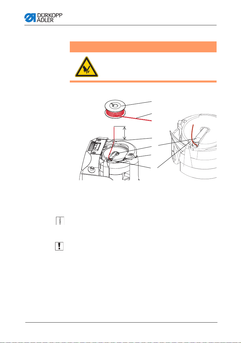
5.3 Threading the needle thread
WARNING
Risk of injury from needle and moving parts!
Turn off the sewing machine before threading the
thread.
5.3.1 Tension plate electromagnetic
In all machines the thread from the thread reel is fed through the
thread guide and to the machine via the unwinding bracket.
Fig. 5: Threading the needle thread - 1-needle machine
1. Thread the machine according to picture.
2. If the machine is equipped for heavy sewing, wind the thread
around the pin (1).
Operating Instructions 878-M PREMIUM - 02.0 - 02/2018 25
Page 28

Operation
(1) - Pin
(2) - Left thread
(3) - Thread lever
②
①
②
③
Fig. 6: Threading the needle thread - 2-needles machine
1. Thread the machine according to the picture. The thread (2)
designed for the left needle is to be threaded in the left tensioners and in the upper hole in the thread lever (3).
2. Threading the side by side arranged needles is in the picture
above.
Fig. 7: Threading the diagonally arranged needles
3. If the machine is equipped for heavy sewing, wind the thread
around the pin (1).
Operating Instructions 878-M PREMIUM - 02.0 - 02/201826
Page 29

Operation
(1) - Thread guide
(2) - Reel stand
(3) - Guide on unwinding bracket
①
②
③
5.3.2 Tension plate electronic
Informace
Tension plate electronic is optional equipment.
In all machines the thread from the thread reel is fed through the
thread guide and to the machine via the unwinding bracket.
Fig. 8: hread guide on the unwinding bracket and machine arm
Operating Instructions 878-M PREMIUM - 02.0 - 02/2018 27
1. Fit the thread reel on the reel stand (2).
2. Insert the thread from the rear to the front through the thread
guide on the unwinding bracket (3).
3. Use e.g. a compressed air gun to feed the thread through the
thread guide (1).
Page 30

Operation
+
(1) - Tightening lever
(2) - Spring tip
(3) - Thread tensioning spring
(4) - Diverter pin
(5) - Tensioner 2
(6) - Tensioner 1
(7) - Preliminary tensioner
(8) - Thread guide
①
②
③
④
⑤
⑥
⑧
⑦
Fig. 9: Threading procedure for needle thread - part 1
4. Feed the thread clockwise from the thread guide (8) around
the preliminary tensioner (7).
5. Feed the thread counterclockwise around tensioner 1 (6).
6. Feed the thread clockwise around tensioner 2 (5).
7. Guide the thread under the diverter pin (4) to the thread
tensioning spring.
8. Lift the tightening lever (1) with the thread.
9. Pull the thread under the spring tip (2).
Operating Instructions 878-M PREMIUM - 02.0 - 02/201828
Page 31

Operation
(9) - Upper thread guide
(10) - Lower thread guide
(11) - Thread guide on the
needle bar
(12) - Needle eye
(13) - Thread regulator
(14) - Thread lever
⑨
⑩
⑪
⑩
⑭
⑬
⑫
Fig. 10: Threading procedure for needle thread - part 2
Operating Instructions 878-M PREMIUM - 02.0 - 02/2018 29
10.Inser t the thread from bottom to top through the hole on the
thread regulator (13).
11.Inser t the thread from the right to the left through the thread
lever (14).
12.Inse r t the thread through the upper thread guide (9).
13.Insert the thread through a hole in the lower thread guide (10).
14.Inse r t the thread through the thread guide on the needle
bar (11).
15.Inser t the thread through the needle eye (12) in such a way
that the loose thread end faces the hook.
Page 32

Operation
(1) - Thread guide
(2) - Thread guide
(3) - Auxiliary tensioner
(4) - Primary rotary tensioner
(5) - Thread regulator
(6) - Tightening spring
①
②
③
④
⑤
⑥
5.3.3 Tension plate rotary
Information
Tension plate rotary is optional equipment, uses the control on
the display and all the setting as an tension plate electronic.
Fig. 11: Threading of needle thread
1. Insert the thread from thread stand through (1) and (2).
2. Guide the thread from the thread guide (2)
around auxiliary tensioner
3. Wind the thread once clockwise arou nd primary tensioner (4).
4. Guide the thread to tightening spring (6).
5. Lift the tightening spring (6) with the thread and pull the thread
under the spring arm.
6. Insert the thread from the bottom up through the thread regulator hole (5) and then to the thread lever.
Operating Instructions 878-M PREMIUM - 02.0 - 02/201830
(3).
counterclockwise
Page 33

Operation
(1) - Guide on unwinding bracket (2) - Reel stand
1
2
5.4 Inserting and winding on the hook thread
WARNING
Risk of injury from needle and moving parts!
Turn off the sewing machine before threading the
thread.
Fig. 12: Thread guide on the unwinding bracket and machine arm
1. Fit the thread reel on the reel stand (2).
2. Insert the thread from the rear to the front through the thread
guide on the unwinding bracket (1).
Operating Instructions 878-M PREMIUM - 02.0 - 02/2018 31
Page 34

Operation
(1) - Thread guide
(2) - Pre-tensioner
(3) - Winder
(4) - Hook thread guide
①
②
③
④
(5) - Bobbin lever
(6) - Bobbin shaft
(7) - Cutter
⑤
⑥
⑦
Fig. 13: Winding on the hook thread - part 1
3. Insert the thread in a wavelike manner through the 3 holes of
the thread guide (1): from top to bottom through the left hole,
from bottom to top through the hole in the middle and finally
from top to bottom through the right hole.
4. Guide the thread counterclockwise around the pretensioner (2).
5. Insert the thread in a wavelike manner through the 2 holes of
the hook thread guide (4): from bottom to top through the left
hole and from top to bottom through the right hole.
6. Guide the thread to the winder (3).
Fig. 14: Winding on the hook thread - part 2
7. Clamp the thread behind the cutter (7) and tear off the loose
end behind it.
8. Fit the bobbin on the bobbin shaft (6).
9. Turn the bobbin clockwise until it clicks.
10.Pull the bob bin lever (5) up.
Operating Instructions 878-M PREMIUM - 02.0 - 02/201832
Page 35

Operation
Damage to the sewing feet or needle plate possible if the
thread is wound on without material.
Lock the top roller in place in the highest position.
ATTENTION
The hook thread is normally wound on when sewing is in progress. However, you can also wind on the hook thread without
sewing, e.g. if you require a full bobbin in order to start sewing.
Winding procedure
1. Switch on the sewing machine.
2. Press the foot pedal forwards.
The machine sews and winds the hook thread from the
thread reel onto the bobbin.
When the bobbin is full, the machine automatically stops
winding. The bobbin lever moves down.
The cutter is automatically moved into its basic vertical
position.
3. Pull off the full bobbin.
4. Tear off the thread behind the cutter.
5. Insert the full bobbin in the hook
( Replacing the hook thread bobbin, p. 34).
6. Repeat the winding-on procedure with an empty bobbin, as
described above.
Operating Instructions 878-M PREMIUM - 02.0 - 02/2018 33
Page 36
5.5 Replacing the hook thread bobbin
(1) - Bobbin
(2) - Thread end
(3) - Tensioning spring
(4) - Bobbin housing flap
(5) - Slot
(6) - Slot
①
10
②
③
④
⑤
⑥
WARNING
Risk of injury from needle and moving parts!
Switch off the sewing machine before replacing
the hook thread bobbin.
Fig. 15: Replacing the hook thread bobbin
Operation
1. Push up the bobbin housing flap (4).
2. Remove the empty bobbin.
3. Insert a full bobbin (1):
Important: Insert the bobbin (1) with the thread end (2) orient-
ed according to the picture.
4. Thread the thread through the slot (5) and slot (6).
5. Close up the bobbin housing flap (4) and fasten the thread
under the tensioning spring (3).
6. Trim the thread end according to the picture.
Operating Instructions 878-M PREMIUM - 02.0 - 02/201834
Page 37

Operation
+
–
(1) - LEDs on the machine arm
①
Automatic
remaining thread
monitor
For machines with automatic remaining thread monitor:
If the hook thread needs to be replaced, the LED indicator lamps
(2) light up on the machine arm. The left light is for the left-hand
hook, and the right light is for the right-hand hook.
Fig. 16: Remaining thread monitor
Each of the bobbins has a thread supply groove that is embedded
in the bobbin core.
Important: Insert the bobbin in the hook in such a way that the
thread supply groove faces down. Otherwise, the remaining thread
monitor will not work.
Operating Instructions 878-M PREMIUM - 02.0 - 02/2018 35
Page 38

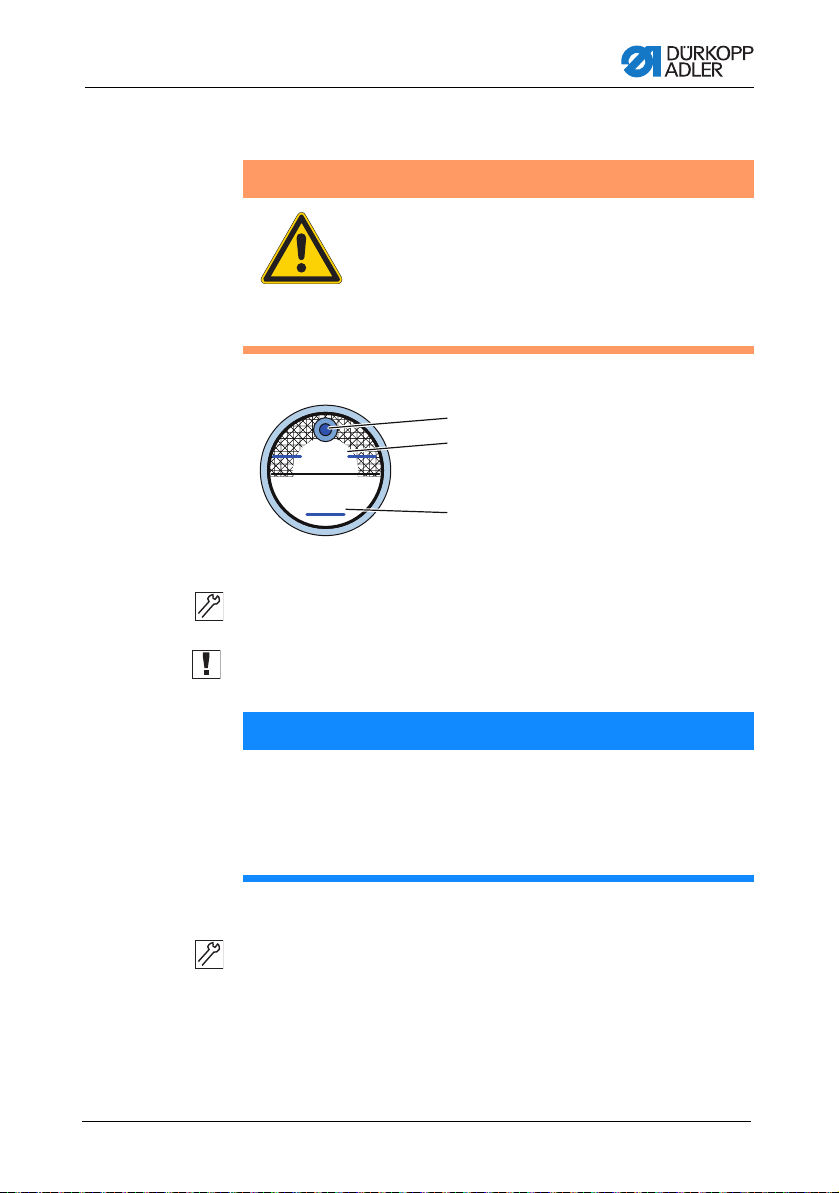
Operation
(1) - Equal tension of the needle and hook threads
(2) - Hook thread tension greater than needle thread tension
(3) - Needle thread tension greater than hook thread tension
①
②
③
5.6 Thread tension
There tension of the needle thread and hook thread determines
where the thread interlaces.
Correct setting
The threads should normally interlace in the exact middle of the
material. When setting, typically only the tension of the needle
thread is altered, while the tension of the hook thread remains
unchanged.
5.6.1 Setting needle thread tension for el. magnetic
tension plate
General
To increase tension:
1. Turn regulator clockwise.
To reduce tension:
1. Turn regulator counter-clockwise.
Operating Instructions 878-M PREMIUM - 02.0 - 02/201836
Page 39

Operation
①
②
(1) - Pre-tensioner
(2) - Auxiliary tensioner
(3) - Primary tensioner
(4) - Lever
③
④
Fig. 17: Setting needle thread tension
Setting pre-tensioner (1)
Set the pre-tensioner (1) so that it has the lowest tension possible,
but so high that, when taking out the sewn material after the
preceding trimming (when the tensioners (2) and (3) are switched
off), the thread is not pulled out of the pre-tensioner (1). (Pretensioner (1) is not switched off at the top roller lifting).
Setting tensioners (2) and (3)
The machine can be equipped with a lever (4) for the auxiliary
tensioner (2) temporary switching off. In this case, two thread
tension values can be pre-selected and a good stitch tightening
can be achieved when sewing over a varia b l e nu mb er of layers
of the sewn material with one seam.
1. Switch the auxiliary tensioner off (2) with the lever (4) and sewn
on a smaller numbers of layers.
2. Regulate the thread tension on the primary tensioner (3), until
a proper thread interlacing is achieved (see picture p. 36).
3. Switch the auxiliary tensioner on (2) by the lever (4) shifting
out and sew on a greater number of layers.
4. Regulate the thread tension on the auxiliary tensioner (2) until
a proper thread interlacing is achieved (see picture p. 36).
5. If the machine is not equipped with the lever (4), regulate the
tension by both tensioners (2) and (3) at the same time so that
their nuts are screwed approximately in the same height.
Operating Instructions 878-M PREMIUM - 02.0 - 02/2018 37
Page 40

Switching on/off thread tensioners
①
②
③
④
(1) - Pre-tensioner
(2) - Auxiliary tensioner
(3) - Primary tensioner
(4) - Lever
Obr. 18: Switching on/off thread tensioners
Via hand lever
1. Pull the hand lever (4).
Tensioners (2) and (3) are switched off.
Pre-tensioner (1) is never switched off.
Operation
Via electromagnet
Tensioners (3) and (4) are switched off with an electromagnet at
the automatic top roller lifting. If the automatic top roller lifting at
the machine stop is pre-selected, the tensioners are switched off,
but temporarily only, so that the switching off electric magnet does
not overheat.
• Tensioners (3) and (4) are switched off temporarily during
the trimming cycle.
• Tensioners (3) and (4) are not switched off at the top roller
lifting with hand lever.
Operating Instructions 878-M PREMIUM - 02.0 - 02/201838
Page 41

Operation
①
②
(1) - Adjusting screw (2) - Hole
5.6.2 Setting hook thread tension
WARNING
Risk of injury from needle and moving parts!
Switch off the sewing machine before adjusting
the hook thread tension.
Fig. 19: Setting hook thread tension
The hook thread tension is adjusted using the adjusting screw (1).
Insert a screwdriver through the hole (2).
To increase the tension:
1. Turn the adjusting screw (1) clockwise.
To reduce the tension:
1. Turn the adjusting screw (1) counterclockwise.
Operating Instructions 878-M PREMIUM - 02.0 - 02/2018 39
Page 42

Operation
+
+
–
(1) - Regulator screw (2) - Thread regulator
5.7 Setting the thread regulator
WARNING
Risk of injury from needle and moving parts!
Switch off the sewing machin e be fore sett ing t he
thread regulator.
The thread regulator determines the tension applied to guide the
needle thread around the hook.
Proper setting:
The loop of the needle thread slides at low tension over the thickest
point of the hook.
Fig. 20: Setting the thread regulator
1
1234
1. Loosen the regulator screw (1).
• To increase the tension:
Slide the thread regulator (2) to the right
• To reduce the tension:
Slide the thread regulator (2) to the left
2. Tighten the regulator screw (1).
2
Operating Instructions 878-M PREMIUM - 02.0 - 02/201840
Page 43

Operation
1
(1) - Pedal
①
(1) - Top roller
5.8 Lifting and folding the top roller
Fig. 21: Electronic top roller lifter with pedal
1. Press the pedal (1) halfway back.
The machine stops and lifts top roller.
The top roller remain up as long as the pedal
is pressed halfway back.
or
1. Press the pedal (1) fully back.
The thread cutter is activated and
the top roller is lifted.
Top roller folding
Fig. 22: Top roller folding
1. Fold the top roller (1) in the direction of the arrow.
Operating Instructions 878-M PREMIUM - 02.0 - 02/2018 41
Page 44

Operation
(1) - Top roller in upper position
(2) - Upper position canceled
Risk of crushing when lowering the top roller!
Do not hold your hands under the top roller when
the upper position is released via the pedal or lever.
CAUTION
5.9Holding the top roller in the upper position
There is a lever at the back of the machine for holding the top
roller in the upper position.
Fig. 23: Holding the top roller in the upper position with the lever
1
2
To hold the top roller in the upper position:
1. Push the lever down.
To cancel the lock:
1. Push the lever up.
You can also use the pedal to cancel the upper position:
1. Press the pedal halfway back as when lifting the top roller.
The lever swivels back up and the lock is removed.
Operating Instructions 878-M PREMIUM - 02.0 - 02/201842
Page 45

Operation
(1) - Knee switch
(2) - Switch
5.10Electronic knee lever
The electronic knee lever can be used to control the different
functions of the machine for example switch between two different
stitch lengths or two values of the upper thread tension. You can
also lift the top roller while sewing. The switch on the back of the
knee lever specifies whether the feature is enabled permanently,
or only for the knee lever is pressed.
Fig. 24: Elements of the knee lever
1
2
For permanent switch:
1. Set the switch (2) to the upper position.
• To switch the relevant function:
Push the knee switch (1) to the right.
• To switch off the relevant function:
Push the knee switch (1) to the right again.
For temporary switch:
1. Set the switch (2) to the lower position.
• To switch:
Push the knee switch (1) to the right and keep it pressed.
A new state is retained as long as the knee switch is
pushed to the right.
• To switch off:
Release the knee switch (1).
Operating Instructions 878-M PREMIUM - 02.0 - 02/2018 43
Page 46

Operation
+
+/–
(1) - Favorite button func tions
Keys for:
(2) - Reverse sewing
(3) - Needle position
(4) - Start and end bar tack
(inversion)
(5) - Stitch length preselection
(great/small)
(6) - Auxiliary thread tensioner
(7) - Switch to the next seam section
(customizable)
(8) - Screws for configuring the
favorite button (1)
①
④②⑤③
⑥
⑦
⑧
5.11Quick functions on the keypad
The machine has a keypad on the machine arm for activating
specific functions while sewing.
5.11.1 Activating function keys
Fig. 25: Keypad for quick functions
+/–
Activating a key function
1. Press the key.
Function is activated. The key illuminates.
Deactivating a key function
1. Press the key again.
Function is deactivated. The key turns off.
Operating Instructions 878-M PREMIUM - 02.0 - 02/201844
Page 47

Operation
+/–+/–
④
②
⑤
③
⑥⑦
Fig. 26: Functions keys
Reverse sewing key (2):
When this key (2) is activated, the machine sews in reverse.
Needle positioning key (3):
When this key (3) is activated, the needle moves to a specific
position. This position is determined individually via the parameter
settings. For more information, refer to the Service instructions.
The machine comes configured so that selecting the key (3) will
bring the needle up.
Start and end ba r tack key (4):
This key (4) cancels the general setting for sewing start and end
bar tacks. If bar tacks are on, pressing the key (4) skips the next
bar tack. If bar tacks are off, pressing the key (4) sews the next
bar tack.
Stitch length key (5):
When this key (5) is selected, the machine sews with the greater
stitch length that was programmed for this stitch length on the
control panel.
Auxiliary thread tensioning key (6):
This key (6) activates the programmed auxiliary thread tensioner.
Switch to the next seam section (7):
The key (7) switches to the next seam section. The key is fully
customizable. It is possible to implement other functions as
necessary.
Operating Instructions 878-M PREMIUM - 02.0 - 02/2018 45
Page 48

Operation
+
+/–
(1) - Favorite button
(2) - Screws for the assignment of the favorite button (1)
(3) - Screw in basic position: slot horizontal
(4) - Screw activates the favorite button (1): slot vertical
①
④
③
②
5.11.2 Assigning key functions to the favorite button
You can assign one of the key functions to the favorite button.
Select a function that you frequently use so that you can switch it
on faster while sewing.
Fig. 27: Assigning a key function to the favorite button
+/–
The key function is assigned by turning the screw under the key
until it is vertical. Only one function at a time can be assigned to
the favorite button (1). Therefore, only one of the screws (4) may
be in the vertical position.
All screws must be turned back to their original horizontal position
before a new function is assigned.
To assign a key function:
1. Turn all screws to their original position (2) so that the slots
are horizontal.
2. Turn the screw under the desired key 90° so that the slot is
vertical (3).
5.12Operating the controller
The machine is operated with a DAC Comfort controller
( Settings via the software, p. 71).
Operating Instructions 878-M PREMIUM - 02.0 - 02/201846
Page 49

Operation
(1) - Pedal position +1:
sewing active
(2) - Pedal position 0:
rest position
(3) - Pedal position -1:
moves the sewing feet up
(4) - Pedal position -2:
sewing the end bar tack and
cutting off the thread
5.13Sewing
WARNING
Risk of injury from the needle tip when sewing
is started unintentionally!
Take care not to accidentally press the foot pedal
when your fingers are in the needle tip area.
The pedal starts and controls the sewing process.
Fig. 28: Sewing with the peda
1
2
3
4
Operating Instructions 878-M PREMIUM - 02.0 - 02/2018 47
Initial position:
• Pedal position 0:
Machine stationary, needles up, top roller down.
To position the material to be sewn:
1. Press the pedal halfway back in pedal position -1:
The sewing feet are lifted.
2. Push the material to be sewn into the initial position.
Sewing:
1. Press the pedal forwards in pedal position +1:
The machine sews.
The sewing speed increases the further forward the pedal
is pressed.
Page 50

Operation
To interrupt sewing:
1. Release the pedal in pedal position 0:
The machine stops, needles and top roller are down.
To continue sewing:
1. Press the pedal forwards in pedal position +1:
The machine continues to sew.
To sew over thickened seams:
1. Switch on the elevated top roller stro ke w it h th e knee le ve r
( Electronic knee lever, p. 43).
To change the stitch length:
1. Switch on the 2nd stitch length using the key for the quick
function ( Quick functions on the keypad, p. 44).
To increase the thread tension:
1. Switch on the auxiliary thread tensioner using the key for the
quick function ( Quick functions on the keypad, p. 44).
To sew intermediate bar tacks:
1. Press the reverse sewing button on the keypad
( Quick functions on the keypad, p. 44).
To finish a seam:
1. Press the pedal back completely in pedal position -2:
The machine sews the end bar tack, and the thread cutter
cuts the thread.
The machine stops, needles and sewing feet are up.
2. Remove the sewing material.
Operating Instructions 878-M PREMIUM - 02.0 - 02/201848
Page 51

Maintenance
6 Maintenance
This chapter describes simple maintenance work that needs to be
carried out on a regular basis. The maintenance work can be
carried out by the operating personnel. Advanced maintenance
work may only be carried out by qualified specialists. Advanced
maintenance work is described in the Service instructions.
6.1 Cleaning work
Cleaning the machine
Lint and thread remnants should be removed after every 8 hours
of operation using a compressed air gun or a brush. When
sewing very fluffy material, the machine should be cleaned more
frequently.
WARNING
Risk of injury from flying particles!
Switch off the machine at the main switch before
cleaning the machine.
Flying particles can enter the eyes, causing
injury.
Hold the compressed air gun so that the particles
do not fly close to people.
Make sure no particles fly into the oil sump.
NOTICE
Malfunctions can occur due to a dirty machine.
Lint and thread remnants can impair the operation of the
machine.
Clean the machine at regular intervals as described in the
instructions.
Operating Instructions 878-M PREMIUM - 02.0 - 02/2018 49
Page 52

Maintenance
(1) - Area around the needle
(2) - Area under the throat plate
(3) - Hook
(4) - Cutter on the bobbin winder
①
②
④
③
Fig. 29: Areas requiring special cleaning
Areas particularly susceptible to soiling:
• Cutter on the bobbin winder for the hook thread (4)
• Area under the throat plate (3)
• Hook (2)
• Area around the needle (1)
Cleaning steps:
1. Shut off power by turning off main switch.
2. Remove any lint and thread remnants using a compressed air
gun or a brush.
50 Operating Instructions 878-M PREMIUM - 02.0 - 02/2018
NOTICE
Damage to paintwork may occur when using solventbased cleaners.
Solvent-based cleaners will damage paintwork on the machine.
Use only solvent-free substances for cleaning the machine.
Page 53
Maintenance
MAX
MIN
1
2
3
(1) - Filler opening
(2) - Maximum level marking
(3) - Minimum level marking
6.2 Checking the oil level
WARNING
Skin damage due to contact with oil!
Oil can cause a rash if it comes into contact with
skin.
Avoid any skin contact with the oil.
If oil has come into contact with your skin, wash
the affected areas thoroughly.
Fig. 30: Oil level indicator
Checking the oil level
1. Check the oil level indicator every day:
Important: The oil level must always be between the minimum
level marking (3) and the maximum level marking (2).
NOTICE
Machine damage possible due to incorrect oil level.
Too little or too much oil can damage the machine.
Check the oil level on a daily basis, adding enough oil so oil
level is always between the minimum and maximum
markings.
Refilling oil
Pour in oil through the filler opening (1) as required:
1. Switch off the sewing machine at the main switch.
2. Add oil up to but not past the maximum level marking (2).
3. Press the main switch again to turn the sewing machine
Operating Instructions 878-M PREMIUM - 02.0 - 02/2018 51
back on.
Page 54

Maintenance
Required oil:
Only DA 10 or equivalent oil should be used for the machine, which
has the following properties:
• Viscosity at 40 °C: 10 mm²/s
• Flash point: 150 °C
NOTICE
Machine damage possible due to incorrect oil.
An incorrect oil type can cause damage to the machine.
Only use oil specified in the operating instructions.
CAUTION
Risk of pollution from oil.
Oil is a pollutant and must not enter the sewage
system or the soil.
Collect waste oil carefully and dispose of it and
oily machine parts in accordance with the
applicable statutory regulations.
6.3 Customer service
Contact for repairs if machine is damaged:
Dürkopp Adler AG
Potsdamer Str. 190
33719 Bielefeld, Germany
Tel. +49 (0) 180 5 383 756
Fax +49 (0) 521 925 2594
Email: service@duerkopp-adler.com
Internet: www.duerkopp-adler.com
52 Operating Instructions 878-M PREMIUM - 02.0 - 02/2018
Page 55

Setup
7Setup
WARNING
Risk of injury!
The machine may only be set up by trained
specialists.
Wear safety gloves and safety shoes when
unpacking and setting up.
7.1 Checking the scope of delivery
Important: The scope of delivery depends on your specific order.
1. Check that all parts are present before setup.
Standard equipme nt:
• Machine head
• Oil sump
• Reel stand with unwinding bracket
• Control unit
• Control panel
• Sewing lamp
Optional additional equipment:
•Table top
•Drawer
•Frame
• Pedal
• Knee switch
Operating Instructions 878-M PREMIUM - 02.0 - 02/2018 53
Page 56

Setup
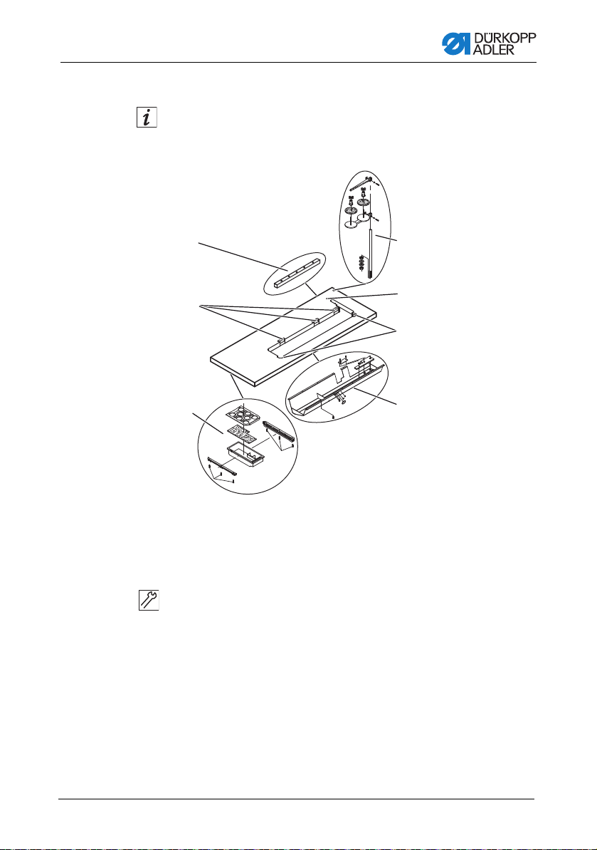
(1) - Upper sections of the inner bars
(2) - Inner bars
(3) - Frame bars
(4) - Cross bar
(5) - Frame foot struts
(6) - Cross strut
(7) - Adjusting screw
(8) - Oil can holder
7.2 Removing the transport locks
All transport securing devices must be removed prior to setup.
1. Remove the lashing straps and wooden blocks from the
machine head, the table, and the frame.
2. Remove the support wedges between the machine arm and
throat plate.
7.3 Assembling frame components
Fig. 31: Assembling frame components
1
2
6
3
5
8
7
2
1
3
4
4
5
1. Screw the cross bar (4) onto the frame bars (3).
2. Screw the oil can holder (8) at the rear to the upper cross
bar (4).
3. Screw the cross strut (6) to the foot struts (5).
4. Insert the inner bars (2) in such a way that the longer end of
the head section (1) is above the longer end of the foot struts
(5).
5. Screw the inner bars (2) down so that both head sections (1)
are at the same height.
Important: Turn the adjusting screw (7) so that the frame has
even contact with the ground.
Operating Instructions 878-M PREMIUM - 02.0 - 02/201854
Page 57
Setup
(1) - Cable duct
(2) - Recesses for lower
hinge parts
(3) - Drawer
(4) - Oil sump
(5) - Corner protrusions
(6) - Hole
(7) - Reel stand
7.4 Completing the table top
The table top is optional.
For drawings that allow you to independently assemble a table
top, refer to the Appendix, p. 87.
Fig. 32: Completing the table top
1
2
3
7
6
5
4
1. Screw the drawer (3) with the left-hand bracket to the underside
of the table top.
2. Screw the oil sump (4) in place under the recess for the
machine.
3. Screw the cable duct (1) to the underside of the table top.
4. Insert the reel stand (7) into the hole.
5. Fasten the reel stand (7) with nut and washer.
6. Screw the thread reel holder and the unwinding bracket onto
the reel stand (7) in such a way that they are exactly on top of
each other.
Operating Instructions 878-M PREMIUM - 02.0 - 02/2018 55
Page 58

7. Insert the blind plug to the hole (6).
1
1
(1) - Screw holes and screws
8. Fit the lower hinge parts into the recesses (2).
9. Fit the rubber corners in the corner protrusions (5).
7.5 Fastening the table top to the frame
Fig. 33: Fastening the table top to the frame
Setup
1. Place the table top on the head sections of the inner bars.
2. Screw the table top firmly with the screws (1) according to the
marks on the table top Tabl e top drawing, p. 95.
Operating Instructions 878-M PREMIUM - 02.0 - 02/201856
Page 59

Setup
1
(1) - Screws
7.6 Setting the working height
The working height is continuously adjustable between 750 and
900 mm (clearance between the floor and upper edge of the table
top).
Fig. 34: Setting the working height
CAUTION
Risk of crushing!
The table top can sink under its own weight when
the screws on the frame bars are released. This
applies even more when the machine head is
already fitted.
Ensure that your hands are not jammed when
releasing the screws.
1. Release the screws (1) on the frame bars.
2. Set the table top to the desired height.
Important: Pull out or push in the table top evenly at both
sides to prevent it from jamming.
3. Tighten the screws (1) on the frame bars.
Operating Instructions 878-M PREMIUM - 02.0 - 02/2018 57
Page 60

Setup
3
2
1
(1) - Strain relief (2) - Control unit
(3) - Screw holder
7.7 Controller
7.7.1 Fitting the control unit
Fig. 35: Fitting the control unit
1. Screw the control unit (2) onto the 4 screw holders (3) under the
table top.
2. Clamp the power cable of the control unit (2) into the strain
relief mechanism (1).
3. Screw the strain relief mechanism (1) under the table top.
Operating Instructions 878-M PREMIUM - 02.0 - 02/201858
Page 61

Setup
SWG DAC
10°
1
2
3
6
5
4
(1) - Pedal rod
(2) - Screw
(3) - Cross strut
(4) - Pedal
(5) - Setpoint device
(6) - Bracket
7.7.2 Fitting the pedal and setpoint device
Fig. 36: Fitting the pedal and setpoint device
Operating Instructions 878-M PREMIUM - 02.0 - 02/2018 59
1. Fit the pedal (4) on the cross strut (3) and align it in such a
way that the middle of the pedal is under the needle. The cross
strut has elongated holes to allow alignment of the pedal.
2. Screw the pedal (4) firmly onto the cross strut (3).
3. Screw the bracket (6) under the table top so that the pedal rod
(1) runs to the pedal (4) at right-angles to the setpoint device
(5).
4. Screw the setpoint device (6) onto the bracket (5).
5. Hang the pedal rod (1) with the ball socket on the setpoint
device (5) and attach to the pedal (4).
6. Pull the pedal rod (1) to the correct length:
Proper setting: 10° inclination with pedal (4) released
7. Tighten the screw (2).
Page 62

7.8 Mounting the machine head
(3) - Locking plate
①
②
③
Fig. 37: Mounting the machine head
CAUTION
Risk of crushing!
The machine head is very heavy.
Take care not to jam your hands when fitting the
machine head.
This especially applies when fitting the upper
hinge parts into the rubber inlays.
Setup
1. Screw the upper hinge parts (1) onto the machine head.
2. Insert the machine head vertically in the recess in the table top.
3. Insert the upper hinge parts (1) into the rubber inlays (2).
4. Above the right hinge place the locking plate (3) and screw it
with two screws to the table.
Operating Instructions 878-M PREMIUM - 02.0 - 02/201860
Page 63

Setup
(1) - Tube of the oil extraction line (2) - Filter
(1) - Tilt sensor (2) - Screws
①
②
7.9 Fitting the oil extraction line
Fig. 38: Fitting the ooil extraction line
1
2
1. Tilt the machine head.
2. Screw the filter (2) into the oil sump with the plastic adapter
to the right.
3. Insert the tube of the oil extraction line (1) into the plastic
adapter.
7.10Fitting the tilt sensor
Fig. 39: Fitting the tilt sensor
1. Tilt the machine head.
2. Place the tilt sensor (1) into the groove in the table top.
3. Screw the tilt sensor (1) with two screws (2).
Operating Instructions 878-M PREMIUM - 02.0 - 02/2018 61
Page 64

Setup
(1) - Knee switch
(2) - Connecting cable
(3) - Plug
7.11Installing the knee switch
Fig. 40: Installing the knee switch
1
2
3
1. Screw the knee switch (1) in front of the oil sump firmly in place
under the table top.
2. Guide the connecting cable (2) to the back between the oil
sump and the control unit.
3. Insert the plug (3) of the connecting cable in the socket of
the control unit.
Operating Instructions 878-M PREMIUM - 02.0 - 02/201862
Page 65
Setup
(1) - Control panel
(2) - Connecting cable plug
(3) - Control panel bracket
①
②
③
7.12Fitting the control panel
Fig. 41: Fitting the control panel
1. Screw the control panel (1) firmly onto the control panel bracket
(3).
2. Insert the plug (2) of the connecting cable in the socket of the
control panel (1).
Operating Instructions 878-M PREMIUM - 02.0 - 02/2018 63
7.13Electrical connection
DANGER
Risk of death from electric shock!
The machine may only be connected by trained
electricians.
Disconnect the power plug before carrying out
work on the electrical equipment.
Make sure the power plug cannot be accidentally
plugged back in.
The voltage on the type plate of the sewing drive
must correspond to the mains voltage.
Page 66

Setup
(1) - Sewing lamp transformer
①
7.13.1 Checking the mains voltage
Important: The voltage on the type plate of the sewing drive must
correspond to the mains voltage.
1. Check the mains voltage before connecting the machine.
7.13.2 Fitting and connecting the sewing lamp and
sewing lamp transformer
DANGER
Risk of death from electric shock!
When you disconnect the sewing machine from
the power supply at the main switch, the supply
voltage for the sewing lamp remains active.
Pull out the power plug before fitting and
connecting the sewing lamp and sewing lamp
transformer.
Make sure the power plug cannot be accidentally
plugged back in.
Fitting the sewing lamp transformer
Fig. 42: Fitting the sewing lamp transformer
1. Screw the sewing lamp transformer (1) in place at the predrilled holes under the table top.
2. Fasten the connecting cable under the table top using cable ties.
3. Establish the plug connection to the supply line for the sewing
lamp.
Operating Instructions 878-M PREMIUM - 02.0 - 02/201864
Page 67

Setup
4
1
2
2
3
(1) - Screw holder
(2) - Adapter cover screws
(3) - 24V/X5 port
(4) - X3 port
Connecting the sewing lamp transformer
Fig. 43: Connecting the sewing lamp transformer
1. Loosen the screw holder(4) for the controller far enough to
allow the controller to be removed..
2. Remove the controller.
3. Loosen the adapter cover screws (3).
4. Connect the supply line:
• for additional sewing lamps to be fitted to the
X3 port (1)
• f or integrated LED sewing lamps connected to
the 24V/X5 port (2)
Operating Instructions 878-M PREMIUM - 02.0 - 02/2018 65
Page 68

Setup
(1) - Nut (2) - Protective earth connection
①
②
7.13.3 Establishing equipotential bonding
DANGER
Risk of death from electric shock!
Disconnect the power plug before establishing
equipotential bonding.
Make sure the power plug cannot be accidentally
plugged back in.
The protective earth conductor conducts away any static charging
of the machine head.
Fig. 44: Establishing equipotential bonding
1. Unscrew the nut (1).
2. Place the loop of grey motor cable on the protective earth
connection (2).
3. Screw and tighten the nut (1).
Information
If is mounted the knee switch with the protective earth cable on
the machine, it must be connect to control unit in the same way.
Operating Instructions 878-M PREMIUM - 02.0 - 02/201866
Page 69

Setup
7.13.4 Connec ting the control unit
NEBEZPEČÍ
Risk of death from electric shock!
Disconnect the power plug before connecting the
control unit.
Make sure the power plug cannot be accidentally
plugged back in.
Connect the control unit as follows:
• Insert the plug of each connecting cable into the sockets on
the back of the control unit.
• Connect the control unit to the power supply using the power
cable.
1. Connect the control unit as specified in the interconnection
diagram, Interconnection diagram, p. 88
7.14Lubrication
WARNING
Skin damage due to contact with oil!
Oil can cause a rash if it comes into contact with
skin.
Avoid any skin contact with the oil.
If oil has come into contact with your skin, wash
the affected areas thoroughly.
All wicks and felt bits of the machine head are soaked in oil at the
factory. This oil is conveyed to the reservoir during use. This is
why you should avoid filling too much oil during initial filling.
Operating Instructions 878-M PREMIUM - 02.0 - 02/2018 67
Page 70

Setup
MAX
MIN
1
2
3
(1) - Filler opening
(2) - Maximum level marking
(3) - Minimum level marking
Fig. 45: Oil level indicator
1. Fill oil through the filler hole (1) to a maximum of 2 mm below
the maximum level marking (2).
NOTICE
MMachine damage possible due to incorrect oil level.
Too little or too much oil can damage the machine.
During initial filling, only pour in oil up to 2 mm below the
maximum level marking.
Required oil:
Only DA 10 or equivalent oil should be used for the machine, which
has the following properties:
• Viscosity at 40 °C: 10 mm²/s
• Flash point: 150 °C
NOTICE
Machine damage possible due to incorrect oil.
An incorrect oil type can cause damage to the machine.
Only use oil specified in the operating instructions.
CAUTION
Risk of pollution from oil.
Oil is a pollutant and must not enter the sewage
system or the soil.
Collect waste oil carefully and dispose of it and
oily machine parts in accordance with the
applicable statutory regulations.
Operating Instructions 878-M PREMIUM - 02.0 - 02/201868
Page 71

Setup
7.15Sewing test
Conduct a sewing test before starting up the machine. Adjust the
machine to the sewing material requirements.
To do this, read the corresponding sections in the Instructions
for use. Read the corresponding chapters in the Service instructions in order to make adjustments to the machine if the
sewing results do not conform to the requirements.
WARNING
Risk of injury from needle and moving parts!
Switch off the sewing machine before replacing
the needle, inserting the thread, inserting the
hook thread bobbin, and adjusting the hook
thread tension and the thread regulator.
Performing a sewing test
1. Insert needle.
2. Wind on the hook thread.
3. Insert the hook thread bobbin.
4. Thread hook thread.
5. Thread needle thread.
6. Set thread tension to material being sewn.
7. Adjust the thread regulator to the material to be sewn.
8. Set top roller pressure to material being sewn.
9. Set top roller stroke to material being sewn.
10.Set stitch length.
11.Transfer the desired quick function from the keypad to the
additional switch.
12.Start sewing test at low speed.
13.Gradually increase sewing speed until working speed is
reached.
Operating Instructions 878-M PREMIUM - 02.0 - 02/2018 69
Page 72

Setup
Operating Instructions 878-M PREMIUM - 02.0 - 02/201870
Page 73
Settings via the software
A
B
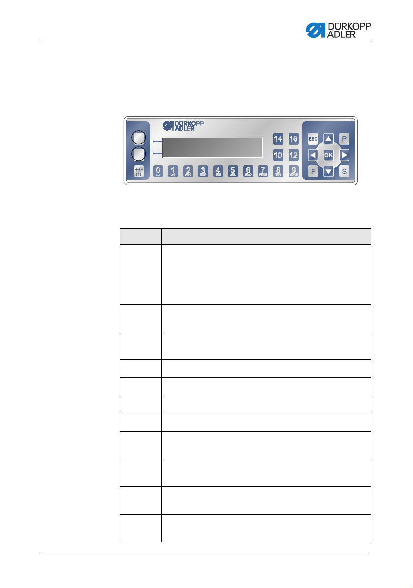
8 Settings via the software
8.1 OP3000 control panel
Fig. 46: Control panel
All settings in the controller for the 878-M PREMIUM are performed
using the OP3000 control panel.
Key Function
0 to 9 Inputting the parameter value (if the field for the parameters
ESC Cancel the function
is activated)
Selection of a parameter that is shown on the display
• Press the key under the desired symbol.
The function is selected.
Exit the menu (changes remain saved)
OK Confirm the settings
Activate the input
P Function is different for each menu
S Function is different for each menu
F Function is different for each menu
A Upper softkey
Operating Instructions 878-M PREMIUM - 02.0 - 02/2018 71
Selection to the right
Selection to the left
Back one menu level
Increase the value
Scroll through the list (upwards)
Decrease the value
Scroll through the list (downwards)
Assignment is different for each menu
Page 74

Settings via the software
878
2016
2016
Key Function
B Down softkey
+/- Altering sense of difference feed
Information
For more information on setting control DAC Comfort can be found
in the relevant parameter sheets.
8.2 Switching the sewing machine on
Fig. 47: Display of the firmware and software version
1. Switch the main switch on.
The displ ay show s the software version:
• On the left of the screen the control panel firmware
• On the right of the screen the controller software version
The machine performs a reference run:
The display shows the program last used, or manual mode.
Fig. 48: Display of the program last used
Fig. 49: Display in Manual mode
Operating Instructions 878-M PREMIUM - 02.0 - 02/201872
Page 75

Settings via the software
8.3 Controller operating modes
The controller of the 878-M PREMIUM has 3 available
operating modes:
• Manual mode (program 000)
• Automatic mode (program 001 - 999)
• Programming/edit mode
Manual mode is the simplest operating mode.
There are no sewing programs and no inputs for individual
sewing sections.
Changes to the top roller pressure, stroke height, stitch
length, thread tension and also the activation of other functions are always implemented immediately.
All the major sewing parameters can be changed manually
during the sewing process.
Automatic mode allows for the execution of setups (seam
program comprised of only one seam section) or complex
seam programs.
Seam programs are divided into individual sections. Each
section is assigned its own individual stitch length, thread tension, etc.
Programming mode allows the operator to create a new
seam program in a quick and easy manner (P flashes above
the program number).
Edit mode can be used to change, delete and copy seam
programs.
Operating Instructions 878-M PREMIUM - 02.0 - 02/2018 73
Page 76

Settings via the software
8.4 Manual mode
Fig. 50: Parameters in manual mode
The following table shows the individual symbols (parameters) on
the display and the functions of the keys on the control panel.
When a parameter is selected, its color on the display changes.
When a parameter is changed, its new value is loaded immediately.
Symbol Meaning
(depending on the assignment)
Programming
• Press the upper softkey
Quick access function (softkey menu)
• Press the lower softkey,
tion (softkey menu), str. 76.
Program number
Value range: 000 to 999
Program 000 indicates that the controller is in Manual
mode.
/ to select the Program parameter.
•Use
/ to change the program number.
•Use
Or:
• Input the program number directly using the keys
0 to 9 and confirm with OK as required.
This takes you into Automatic mode.
8.4.1 Quick access func-
Stitch length
Value range: 0.0 to 7.0 mm (depending on the sewing
equipment)
/ to select the Stitch length parameter.
•Use
/ to change the stitch length
•Use
Thread tension (only for electronic tension plate)
Value range: 1 to 99
•Use
/ to select the Thread tension parameter.
/ to change the thread tension
•Use
Operating Instructions 878-M PREMIUM - 02.0 - 02/201874
Page 77

Settings via the software
Symbol Meaning
P Creating a program
Top roller pressure
Value range: 1 to 14
/ to select the Top roller pressure parame-
•Use
ter.
•Use
/ to change the top roller pressure
Difference feed between top roller and wheel feeder
Value range: 0 to 16 (increments 1)
•Use
/ to select the Difference feed parameter.
•Use +/- to select difference sense
•Use
/ or the numeric keys to change the differ-
ence value
Other parameters
8.4.2 Menu for other settings, str. 77
S.p.m. or seam length in mm
After the thread has been cut off, the display is
retained. Measurement/counting restarts when sewing
starts again.
8.6.1 Creating programs, str. 82
+/- Altering sense of difference feed (wavy line up - top
ESC, F and S No function assigned
OK No function assigned
Operating Instructions 878-M PREMIUM - 02.0 - 02/2018 75
roller feeds faster; wavy line down - top roller feeds
slower)
Page 78

Settings via the software
8.4.1 Quick access function (softkey menu)
Here you have quick access to functions during the sewing
process. You can also assign a function to the upper softkey
1. Press the lower softkey .
The following information is shown on the display:
Fig. 51: Softkey menu
2. Calling up a function:
• Press the numeric key under the desired function.
or
Assigning a function to the upper softkey:
• P ress the numeric key under the desired function and the
upper softkey at the same time.
The function is assigned to the upper softkey and can subse-
quently be called up using this softkey.
3. Press ESC to exit the menu.
Symbol Meaning
Needle position up / down
If sewing is stopped within the seam, the needle is
positioned up or down.
Threading mode
The needle bar moves to the defined position.
The pedal is temporarily locked.
Programming
Added a new sewing programm.
Bobbin mode
Press the pedal forwards for winding.
Press the pedal backwards - bobbin mode is ended.
Operating Instructions 878-M PREMIUM - 02.0 - 02/201876
Page 79

Settings via the software
Symbol Meaning
8.4.2 Menu for other settings
1. Use / to select Other parameters .
2. Press the OK key.
3. Use / to select the desired parameter.
4. Press the OK key to select the parameter.
5. Change values using the / keys.
6. Press the OK key to confirm your selection.
7. Press or ESC to exit the menu
Resetting the bobbin stitch counter
After pressing the stitch counter is reset to zero.
Foot lifting
After pressing the top roller lift.
Thread clamp
Is not mounted.
Backtack suppression/recall
Manual thread trimming
After pressing during sewn work the thread is cut.
Operating Instructions 878-M PREMIUM - 02.0 - 02/2018 77
Page 80

Symbol Meaning
cor.
Max Speed
Value range: 50 to 2500 (depending on stitch length)
Thread Trim
Value range: on/off
Thread Clamp - is not mounted
Value range: on/off
Point Position
Value range: 0 až 360°
Set value defines the needle bar position after pressing
electronic handwheel.
Start Tack
Dialog box for defining the start bar tack
End Tack
Dialog box for defining the end bar tack
Settings via the software
Foot
Top roller position when sewing stops and after the
thread is cut
Bobbin (thread monitor) - only on request
Value range: on/software/monitor
Info Screen
Display more information on the display
Speed Corr.
Setting the correction of various sewing parameters
depending on the speed of the machine.
Fabric Thickness
Setting the correction of various sewing parameters
depending on the material thickness.
Operating Instructions 878-M PREMIUM - 02.0 - 02/201878
Page 81

Settings via the software
8.4.3 Sewing
Altering parameters whilst within the seam
1. Move the pedal to the 0 position.
2. Change the desired parameter on the control panel.
3. Press the pedal forwards and sew.
The seam will be sewn using the altered parameter value.
8.5 Automatic mode
Program numbers 001 to 999.
1. Use
2. Use
The controller switches to automatic mode and the following
Fig. 52: Displey in Automatic mode
/ to select the Program parameter.
/ to select the program number 1 or another one (if
available).
information appears on the display:
The following table shows the individual symbols on the display
and the functions of the keys on the control panel.
Operating Instructions 878-M PREMIUM - 02.0 - 02/2018 79
Page 82
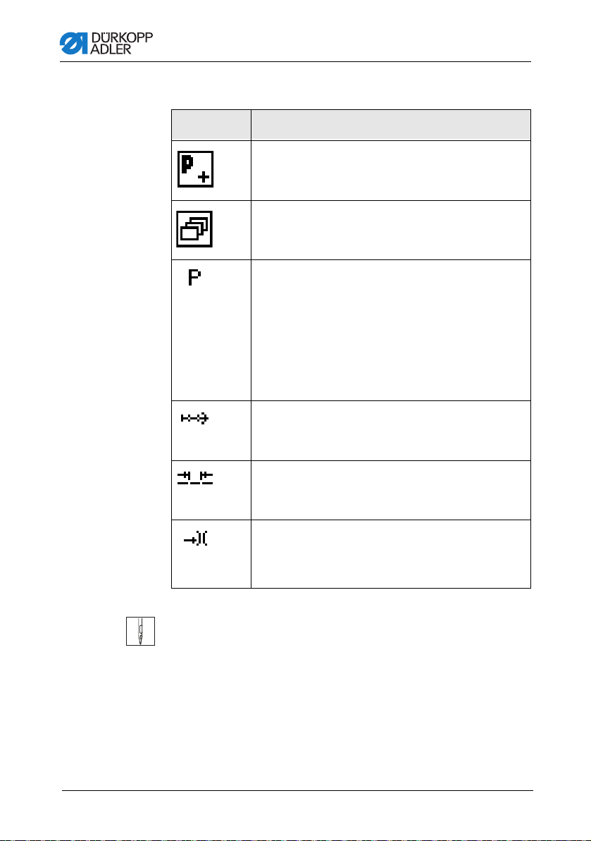
8.5.1 Before starting sewing
Symbol Meaning
Programming (depending on assignment)
• Press the upper softkey
Quick access function (softkey menu)
• Press the lower softkey
tion (softkey menu), str. 76.
Program number
Value range: 000 to 999
•Use
/ to select the Program parameter.
•Use
/ to change the program number.
Or:
• Input the program number using the 0 - 9 keys
and confirm with OK as required.
If you select program 000, the controller selects
Manual mode
Seam sections
Number of sections contained in the current program.
Settings via the software
8.4.1 Quick access func-
Stitch length correction factor
Value range: -50 to +50 %
Alters the stitch length in all seam sections.
Thread tension correction factor (only for electronic
tension plate)
Value range: -50 to +50 %
Alters the thread tension in all seam sections.
1. Sew, press the pedal or press the OK key.
The program switches to the 1st section.
Operating Instructions 878-M PREMIUM - 02.0 - 02/201880
Page 83

Settings via the software
8.5.2 Sewing
1. Press the pedal forwards and sew.
The following information is shown on the display:
Fig. 53: Display when sewing in Automatic mode
The parameter values for the current section are shown on the
display.
The program bar shows the progress of the seam.
The number under the current section shows the number of stitch-
es yet to be completed / the outstanding length of the section.
The program bar shows half the current section in bold.
Fig. 54: Current section
Completed sections are shown fully in bold.
Fig. 55: Completed section
The following table lists the functions that can be performed in the
course of the seam.
Key/Pedal Function
/
/
Pedal halfway
back
Pedal fully
back
Lower softkey Softkey menu
Stop forward/back or to the start of the section
Correction of the thread tension (only for electronic
tension plate)
The value is saved.
Raise the top roller
Cut off the thread
The program remains stopped at the cutoff point.
8.4 Manual mode, str. 74
Operating Instructions 878-M PREMIUM - 02.0 - 02/2018 81
Page 84
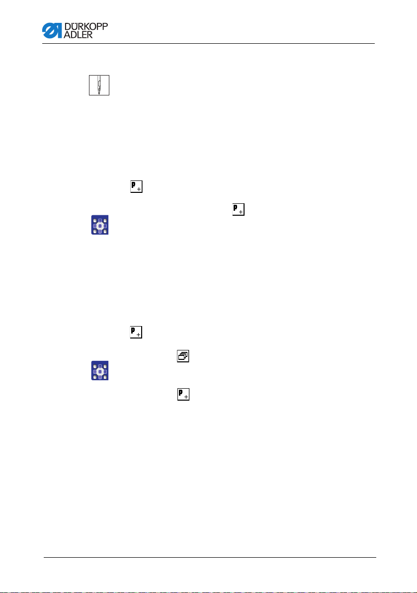
8.5.3 Canceling the program
1. Cut off (press the pedal fully back).
The prog ra m is interrupted.
8.6 Programming/edit mode
8.6.1 Creating programs
If is assigned to the upper softkey:
1. Press the upper softkey .
The following display appears:
Fig. 56: Programming
2. Continue with handling step 3.
Settings via the software
If is not assigned to the upp er softkey:
1. Press the key.
The softkey menu appears.
2. Press the key.
The controller displays the next free program number.
3. Press OK to load the program number.
Or:
Operating Instructions 878-M PREMIUM - 02.0 - 02/201882
Page 85

Settings via the software
4. Select another program number using / or input a program
The following information is shown on the display,
Fig. 57: Programming display
5. Press the upper softkey.
The following table shows the individual symbols on the display
and the functions of the keys on the control panel.
Symbol Meaning
number using the keypad keys 0 - 9 and then press OK.
the P in the program number field flashes:
Auto Forward
Value range: on/off
Add section
Delete section
Number of current program to be created
No function assigned
Current section
/ to select the Section parameter.
•Use
/to switch to the next/previous section.
•Use
• Press the OK key to edit other parameters for the
8.6.4 Editing programs, str. 86.
section,
Stitch length for the current section
Value range: 0.0 to 7.0 mm
/ to select the Stitch length parameter.
•Use
•Use
/ to change the stitch length.
Operating Instructions 878-M PREMIUM - 02.0 - 02/2018 83
Page 86

Symbol Meaning
Thread tension value (%) for the current section
(only for electronic tension plate)
Value range: 0 to 99
/to select the Thread tension parameter.
•Use
•Use
/ to change the thread tension.
Top roller pressure
Value range: 1 to 14
•Use
/ to select the Top roller pressure parame-
ter.
•Use
/ to change the top roller pressure
Difference feed between top roller and wheel feeder
Value range: 0 to 16 (increments 1)
•Use
/ to select the Difference feed parameter.
•Use +/- to select difference sense
Use
/ or numeric keys to change the difference
value
Number of stitches /
length of the current section in mm
Settings via the software
Programming mode offers two options for creating new seam
programs:
• Creating a program by keyboard input
• Creating a program by teach-in
Operating Instructions 878-M PREMIUM - 02.0 - 02/201884
Page 87

Settings via the software
8.6.2 Creating a program by keyboard input
1. Use to switch to section selection .
2. Use to activate the section.
3. Set all parameters for this section.
4. To set up another section, use on the section display to
5. Use to activate the section and set all parameters.
6. Repeat steps 4 and 5 to define up to 30 sections if necessary.
7. Press the ESC key.
The prog ra m is save d .
The machine switches to Automatic mode.
8.6.3 Creating a program by teach-in
1. Press the Teach-In key.
2. Set the parameters for the section (stitch length, thread ten-
3. Press the pedal and complete the seam section up to the
4. To set other parameters for another seam section, use to
5. Set the parameters.
6. Repeat steps 4 and 5 to define up to 30 sections if necessary.
7. Press the pedal back.
The program switches to Edit mode.
8. If necessary, add other parameters for all seam sections
9. Press the ESC key.
The prog ra m is save d .
The machine switches to Automatic mode.
switch to the next section.
The program that was just created is selected.
sion, top roller pressure and top roller stroke).
desired position on the material.
add a new seam section.
(bartack, sewing speed, thread cutter, top roller lifter, etc.).
The program that was just created is selected.
Operating Instructions 878-M PREMIUM - 02.0 - 02/2018 85
Page 88
Settings via the software
8.6.4 Editing programs
1. In Automatic mode, press the P key.
The controller switches to Edit mode.
The program previously selected can now be edited.
The following information is shown on the display, and the P
in the program number field flashes:
Fig. 58: Display in Edit mode
1. Use / and / to select the program to be edited and the
section.
The selected section is shown bold in the program bar.
2. Use
/ to select the parameter to be changed for the respec-
tive section, and use
/ to change it.
3. Use to add a new section.
4. Use to delete a section.
Operating Instructions 878-M PREMIUM - 02.0 - 02/201886
Page 89

Settings via the software
8.6.5 Changing further parameters for the current
1. Use /to select the field .
2. Press the OK key.
The submenu opens.
3. Use
4. Press the OK key to activate or deactivate the parameter or
Symbol Meaning
section
/ to select the desired parameter .
/ to edit the value and confirm the change by pressing
use
OK.
Stich Count
Auto Forward
Top roller Pressure
Max Speed
Seq. End Modes
Start Tack
Dialog box for defining the start bar tack
End Tack
Dialog box for defining the end bar tack
Needle up
Operating Instructions 878-M PREMIUM - 02.0 - 02/2018 87
Page 90

Settings via the software
Symbol Meaning
Foot lifted
Top roller lift height
Backwards
5. Exit the submenu using ESC or
The changed values are stored immediately.
6. Exit Edit mode using ESC.
Operating Instructions 878-M PREMIUM - 02.0 - 02/201888
Page 91

Settings via the software
8.6.6 Changing further parameters for the selected
This menu allows further parameters for the current seam program
to be changed.
1. Use /to select the field .
2. Press the OK key.
The submenu opens.
3. Use
4. Press the OK key to activate or deactivate the parameter or
Symbol Meaning
program
/ to select the desired parameter .
/ to edit the value and confirm the change by pressing
use
OK.
Program Name (program name)
Next Progr.
Thread Tension (thread tension) - only for electronic
tension plate
Sets up an auxiliary thread tensioner that can be
activated during the sewing process with press of a
button.
Stitch Length (stitch length)
Defines a second stitch length that can be activated
during the sewing process with press of a button.
Bobbin (setting thread monitor)
Daily Piece Counter (day piece counter) - by number
thread trim
Point Pos.
After pressing moves to a specified position in degrees.
Operating Instructions 878-M PREMIUM - 02.0 - 02/2018 89
Page 92

Settings via the software
cor.
Symbol Meaning
Info Screen
Display more information on the display
Speed Corr.
Setting the correction of various sewing parameters
depending on the speed of the machine.
Fabric Thickness
Setting the correction of various sewing parameters
depending on the material thickness.
5. Exit the submenu using ESC or .
The changed values are stored immediately.
6. Exit Edit mode using ESC.
8.6.7 Copying the program
The selected program is copied into a new program number.
1. Press the key.
The softkey menu appears.
Fig. 59: Softkey menu
2. Press the key.
The following display appears:
Fig. 60: Copying the program
The controller displays the next free program number.
Operating Instructions 878-M PREMIUM - 02.0 - 02/201890
Page 93

Settings via the software
3. Press OK to load the program number.
The program number is loaded.
Fig. 61: Display after specifying the program number
4. Load the desired changes into the new program.
5. Press the ESC key.
The controller exits Programming mode and reverts to Auto-
8.6.8 Deleting a program
The selected program is deleted.
Or:
Select another program number using
/ or input a
program number using the keypad keys 0 - 9 and then press
OK.
The following display appears, with the program number
flashing:
matic mode.
1. Press the key.
The softkey menu appears.
Fig. 62: Softkey menu
2. Press the key.
3. Press the ESC key.
The controller exits Programming mode and reverts to Auto-
matic mode.
Operating Instructions 878-M PREMIUM - 02.0 - 02/2018 91
Page 94

Settings via the software
8.7 Simplified display menu
Obr. 63: Control panel
Icons in the top line are the same as in the standard menu, icons
in the bottom line have special functions and will be operated with
the keys as follows:
Key Function
2Start Tack
Switch between off/single/double backtacking. Backtacking
multi icon appears just in case of special sett-up in
backtacking menu. Number of stitches transfers from
backtacking menu also.
3 End Tack
Switch between off/single/double backtacking. Backtacking
multi icon appears just in case of special sett-up in
backtacking menu. Number of stitches transfers from
backtacking menu also.
4 Thread Trim
Range of values: on/off
5 Needle Position
6 Foot Lifting (foot lifting in stitch/after trimming)
Switch between needle position up/down.
After pedal release the foot lifts automatically, after
depressing the pedal is automatically lowered.
Information
How to choose between the standard and simplified display menu
is available in the Service Instructions.
Operating Instructions 878-M PREMIUM - 02.0 - 02/201892
Page 95

Disposal
9 Disposal
Do not dispose of the machine in the general household waste.
The machine must be disposed of in a suitable and proper manner
and in accordance with all applicable national regulations.
CAUTION
Risk of pollution from improper
disposal!
Improper disposal of the machine can result in
serious pollution.
ALWAYS comply with the legal regulations
regarding disposal.
When disposing of the machine, be aware that it consists of a
range of different materials (steel, plastic, electronic components,
etc.). Observe the applicable national regulations when disposing
of these materials.
Operating Instructions 878-M PREMIUM - 02.0 - 02/2018 93
Page 96

Disposal
94 Operating Instructions 878-M PREMIUM - 02.0 - 02/2018
Page 97

Appendix
10Appendix
10.1Table top drawing
Dimensions for manufacturing a table top, part 1
Operating Instructions 878-M PREMIUM - 02.0 - 02/2018 95
Page 98

Dimensions for manufacturing, part 2
Appendix
96
Operating Instructions 878-M PREMIUM - 02.0 - 02/2018
Page 99

Appendix
10.2Component layout on underside of table top
Operating Instructions 878-M PREMIUM - 02.0 - 02/2018 97
Page 100

10.3Interconnection diagram
Appendix
98
Operating Instructions 878-M PREMIUM - 02.0 - 02/2018
 Loading...