

Page 1

867
867-M
867-M PREMIUM
Additional Instructions
Remaining thread monitor
Page 2

IMPORTANT
READ CAREFULLY BEFORE USE
KEEP FOR FUTURE REFERENCE
All rights reserved.
Property of Dürkopp Adler AG and protected by copyright. Any reuse of these contents,
including extracts, is prohibited without the prior written approval of Dürkopp Adler AG.
Copyright © Dürkopp Adler AG 2018
Page 3

Table of Contents
1 General information ...................................................................3
1.1 Components of the kit...................................................................3
1.2 Kits for M-TYPE PREMIUM..........................................................5
2 Assembling the remaining thread monitor .............................. 6
2.1 Assembling the remaining thread monitor....................................6
2.2 Connecting the remaining thread monitor ....................................7
2.2.1 Connecting the remaining thread monitor
on Classic machines.....................................................................7
2.2.2 Connecting the remaining thread monitor
on PREMIUM machines ............................................................. 10
2.3 Setting the remaining thread monitor electrically........................ 12
2.4 Software settings........................................................................14
2.4.1 Parameter settings for classes 867 and 867-M..........................14
2.4.2 Parameter settings for class 867-M PREMIUM..........................16
Additional Instructions 867/867-M PREMIUM - 00.0 - 07/2018 1
Page 4

Table of Contents
2 Additional Instructions 867/867-M PREMIUM - 00.0 - 07/2018
Page 5
General information
1 General information
The remaining thread monitor (RTM) can be used with all 1-needle and
2-needle machines equipped with a thread cutter.
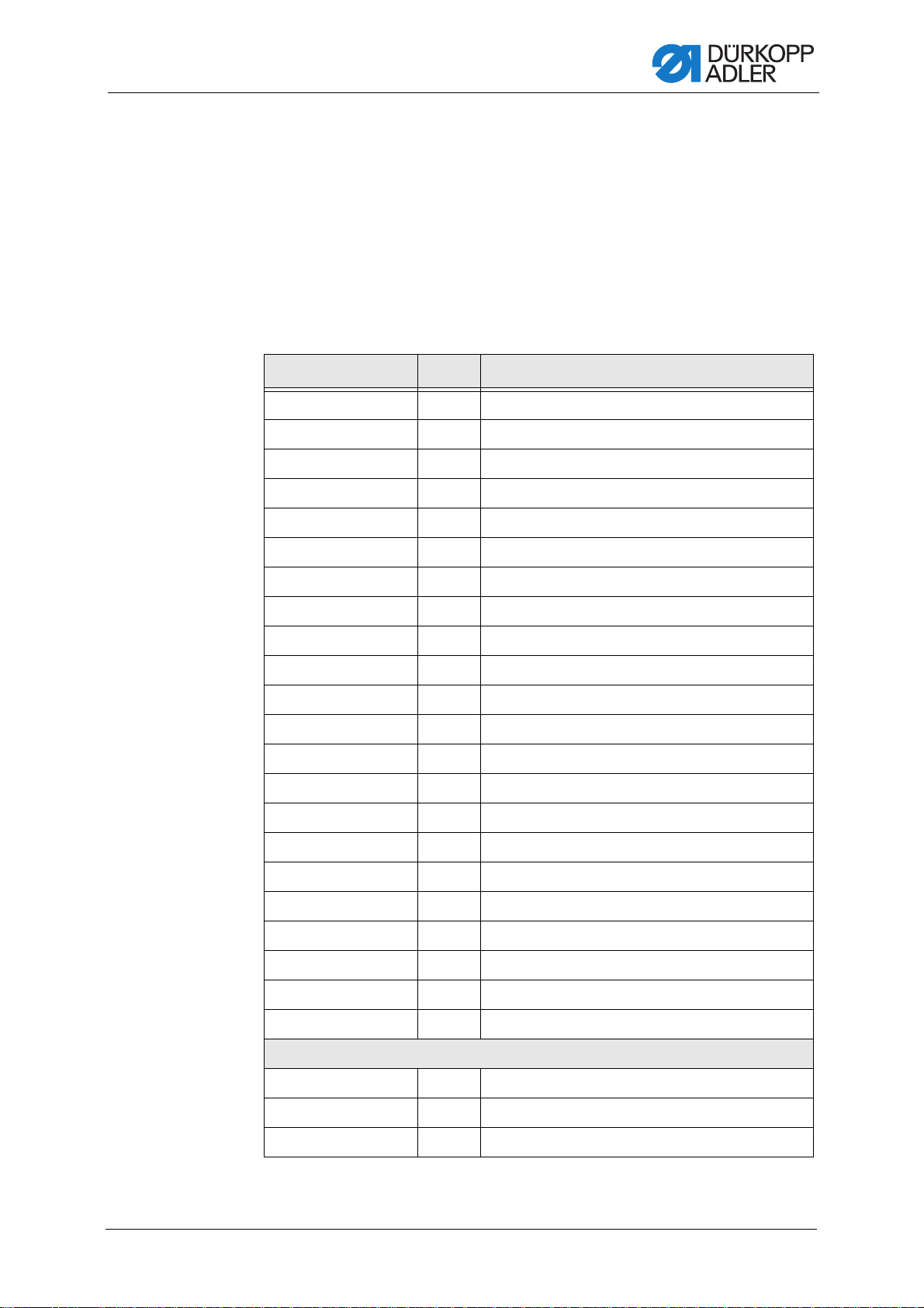
1.1 Components of the kit
Check whether the scope of delivery for the kit is correct prior to installation.
The different kits for the remaining thread monitor differ in some parts, which
are listed separately below.
Part number Quantity Description
0667 155824 1 RTM carrier
0699 979265 1 Hose PUR, 0.9 m
9840 120106 3 Cable holder
9815 925002 1 Light barrier
9850 867003 1 Circuit board
9870 867003 1 Cable (RTM cable machine head)
9870 367003 1 Cable (367 valve)
0667 155840 1 Holder
9204 201667 8 Pan-head screw M4x10-H
9830 501010 4 Spacer
9710 900031 1 Connection plate
091 1 000478 1 O-ring
0999 240389 1 Hose connector
9203 003097 2 Cylinder-head bolt M3x16
9204 200517 2 Pan-head screw M2x20-H
9710 061200 1 Magnet valve
0667 155930 1 Cover
9203 003157 2 Cylinder-head bolt M3x30
9710 982003 1 Silencer
9840 121002 3 Cable tie
9840 120025 2 Mounting clip
0791 867720 EN 1 Additional Instructions
Kit 0867 590104
9202 002077 1 Cylinder-head bolt M4x10
0767 150170 3 Bobbin
0867 150240 3 Bobbin
Additional Instructions 867/867-M PREMIUM - 00.0 - 07/2018 3
Page 6

Part number Quantity Description
0867150170 1 Compression spring
0570 001847 1 Blanking plug
9203 003177 2 Cylinder-head bolt M3x40
9231 000347 2 Hexagon nut
Kit 0867 590114
0667 156014 1 Bobbin case
0667 155614 1 Bobbin case
9202 002078 1 Cylinder-head bolt M4x10
0667 150880 3 Bobbin
0867 150560 3 Bobbin
0867 150170 1 Compression spring
0570 001847 1 Blanking plug
General information
9203 003177 2 Cylinder-head bolt M3x40
9231 000347 2 Hexagon nut
Kit 0867 590124
9202 002077 2 Cylinder-head bolt M4x10
0767 150170 6 Bobbin
0867 150240 6 Bobbin
9790 030020 1 Y-connection
0667 155594 2 Bobbin case
0867 150170 2 Compression spring
Kit 0867 590134
0667 156014 2 Bobbin case
0667 155614 2 Bobbin case
9202 002078 2 Cylinder-head bolt M4x10
0667 150880 6 Bobbin
0867 150560 6 Bobbin
9790 030020 1 Y-connection
0867 150170 2 Compression spring
4 Additional Instructions 867/867-M PREMIUM - 00.0 - 07/2018
Page 7

General information
1.2 Kits for M-TYPE PREMIUM
Important
Machines of the M-TYPE PREMIUM class are not equipped with
compressed air. If you want to assemble the remaining thread monitor
to a PREMIUM machine, you will need the following additional kits:
(see Parts List):
• 9780 000108: Compressed air maintenance unit
• 0867 593534: Pneumatic connection PREMIUM
• 0797 003031: Pressure line K
Additional Instructions 867/867-M PREMIUM - 00.0 - 07/2018 5
Page 8

Assembling the remaining thread monitor
①
②
③
④
①
①
②
③
2 Assembling the remaining thread monitor
WARNING
Risk of injury from sharp and moving parts!
Puncture or crushing possible.
Switch off the machine before assembling the
residual thread monitor.
2.1 Assembling the remaining thread monitor
Fig. 1: Assembling the remaining thread monitor (1)
(1) - Remaining thread monitor
(2) - Hose
To assemble the remaining thread monitor:
1. Remove old bobbin case and replace it with the new bobbin case from
the kit.
2. Tighten the pre-assembled carriers (4) using the screws (3).
As a rule, the front edge of the remaining thread monitor (1) must be
assembled parallel to the front edge of the carrier (4).
3. Connect the hose (2) used for the blow-off.
(3) - Screws
(4) - Carrier
6 Additional Instructions 867/867-M PREMIUM - 00.0 - 07/2018
Page 9

Assembling the remaining thread monitor
②③
①
ABC
4. Set the position of the remaining thread monitor (1) so that the light
beam hits the reflective surface of the bobbin through the slot in the
bobbin case.
2.2 Connecting the remaining thread monitor
2.2.1 Connecting the remaining thread monitor on Classic machines
Fig. 2: Connecting the remaining thread monitor on Classic machines (1)
(1) - Remaining thread monitor carrier plate
(2) - Circuit board
(3) - Spacer
To connect the remaining thread monitor:
1. Insert spacer (3) into the holes of the remaining thread monitor carrier
plate (1).
2. Attach the circuit board (2).
3. Connect the cables to the circuit board (2):
• A = Valve circuit board
• B = Light barrier, left needle
• C = Light barrier, right needle
Additional Instructions 867/867-M PREMIUM - 00.0 - 07/2018 7
Page 10

Assembling the remaining thread monitor
④⑤
⑥
⑦
X24
Fig. 3: Connecting the remaining thread monitor on Classic machines (2)
(4) - Cable clamps (5) - Screw
4. Fasten the cables with the cable clamps (4) to the base plate of the
remaining thread monitor control.
5. Screw the remaining thread monitor carrier plate (1) with the circuit
board (2) into the base plate using the screws (5).
Fig. 4: Connecting the remaining thread monitor on Classic machines (3)
(6) - Cable (7) - Cable holder
6. Route the cable (6) through the cable holder (7) in the machine arm:
8 Additional Instructions 867/867-M PREMIUM - 00.0 - 07/2018
from the remaining thread monitor control to the valve circuit board.
7. Connect the cable (6) to plug connection X24 of the valve circuit board.
8. Guide the cables of the remaining thread monitors through the holes
in the base plate and fix them to the existing cables with cable tie.
Page 11

Assembling the remaining thread monitor
⑩
⑧⑨
X22
9. Roll up the remaining thread monitor cables that are too long and fix
them to the base plate of the remaining thread monitor control with
cable ties.
Fig. 5: Connecting the remaining thread monitor on Classic machines (4)
(8) - Y-connection
(9) - Hoses
10. Assemble the valve (10).
Ensure that the sealing washer is in the correct position when doing this.
11. Disassemble the valve unit.
12. Screw the valve (10) to the valve rail.
13. Assemble the valve unit.
14. Connect the hoses (9) of the remaining thread monitor to the valve.
With right AND left remaining thread monitor: Connect hoses (9)
to Y-connection (8).
15. Assemble hoses and cables with clips to the oil return line and to the
knee lever shaft.
16. Connect the magnet valve electrically to the valve circuit board.
• X22, PIN 1/7/8 (+) and PIN4 (FL)
OR
• X22, PIN 1/7/8 (+) and PIN2 (FA)
(10) - Valve
Additional Instructions 867/867-M PREMIUM - 00.0 - 07/2018 9
Page 12

Assembling the remaining thread monitor
①
2.2.2 Connecting the remaining thread monitor on PREMIUM machines
To connect the remaining thread monitor:
• For XXX PREMIUM machines: Remove the valve cover
• For XXX-M PREMIUM machines: Remove the motor cover
Fig. 6: Connecting the remaining thread monitor on PREMIUM machines (1)
(1) - Circuit board
1. Loosen the circuit board (1).
To do so, push the circuit board (1) down and off the white spacers.
2. Screw the connection plate and magnet valve together.
10 Additional Instructions 867/867-M PREMIUM - 00.0 - 07/2018
Page 13

Assembling the remaining thread monitor
②
③
④
①
⑤⑥⑦
Fig. 7: Connecting the remaining thread monitor on PREMIUM machines (2)
(1) - Circuit board
(2) - Magnet valve
3. Insert the magnet valve (2) into socket X16 on the circuit board (1).
If socket X16 is already occupied, use socket X17 or socket X18.
4. Assemble the circuit board (1).
5. Tighten the connection plate (4) on the holder (3).
Fig. 8: Connecting the remaining thread monitor on PREMIUM machines (3)
(3) - Holder
(4) - Connection plate
(5) - Compressed air maintenance unit
(6) - Hose
(7) - Valve
Additional Instructions 867/867-M PREMIUM - 00.0 - 07/2018 11
Page 14

Assembling the remaining thread monitor
①②③
⑦⑧④⑤⑥
6. Assemble the compressed air maintenance unit (5) to the stand.
7. Use an R 1/4” hose coupling to connect the connection hose to
the compressed air supply.
8. Set the operating pressure to 6 bar.
9. Connect the hose (6) to the valve (7).
2.3 Setting the remaining thread monitor electrically
Important
The remaining thread monitor is delivered with a basic setting.
As a rule, the sensitivity of the residual thread monitor does NOT have
to be set!
The pre-set sensitivity of the remaining thread monitor may only be
changed if the remaining thread monitor is not working properly.
Fig. 9: Setting the remaining thread monitor electrically
(1) - Plug connection light barrier,
right hook
(2) - Plug connection light barrier,
left hook
(3) - Plug connection inputs and outputs
of the control
(4) - Plug connection switched output
(5) - Potentiometer left hook
(6) - LED
(7) - Potentiometer right hook
(8) - Plug connection auxiliary output
After the machine has been switched on and before it starts sewing, the
remaining thread monitor is in setting mode.
To set the remaining thread monitor:
1. Switch on the machine.
2. Insert an empty bobbin into the hook.
3. Turn the hook to a position that the light beam falls through the slot in
the hook housing onto the bobbin.
4. Set the potentiometer (5) or (7) to the highest sensitivity.
To do this, turn the potentiometer clockwise.
12 Additional Instructions 867/867-M PREMIUM - 00.0 - 07/2018
Page 15

Assembling the remaining thread monitor
5. Turn the hook until the light beam hits the reflective surface on the
bobbin.
The LED (6) lights up for 1 second with each reflection in the setting
mode.
The output to the control and the auxiliary output are switched on.
6. Turn potentiometer (5) or (7) counterclockwise to reduce the sensitivity
until the reflection can just be detected.
When sewing begins, the system leaves setting mode automatically.
Additional Instructions 867/867-M PREMIUM - 00.0 - 07/2018 13
Page 16

Assembling the remaining thread monitor
2.4 Software settings
2.4.1 Parameter settings for classes 867 and 867-M
DAC classic control
Parameter Value Function
Operator level
o 06 00 4 Remaining thread monitor
o 06 05 0 - 9999 Number of stitches for the remaining thread
monitor
o 06 06 0 - 1 Stop sewing motor when the counter
reaches 0
0 = No
1 = Yes
o 06 07 0 - 1 Sewing foot stays down after thread cutting
0 = No
1 = Yes
Technician level
t 06 00 0 - 2 Activation of the remaining thread monitor
0 = Off
1 = Right
2 = Left & right
t 06 01 0 - 1 Remaining thread monitor mode
0 = Dynamic
1=Static
t 06 02 0.0 - 3.300 V Threshold right
t 06 03 0.0 - 3.300 V Intensity right
t 06 04 0.0 - 3.300 V Threshold left
t 06 06 0.0 - 3.300 V Intensity left
t 06 06 0 - 1 Confirmation required after warnings
0 = No
1 = Yes
14 Additional Instructions 867/867-M PREMIUM - 00.0 - 07/2018
Page 17

Assembling the remaining thread monitor
Efka control (class 867 only)
Recommended mode for remaining thread monitor function:
Parameter F-195 on value "3"
Parameter Value Function
F-195 0 Remaining thread monitor off
F-195 1 No stop after 1st detection Bobbin empty,
F-195 2 With stop after 1st detection Bobbin empty,
F-195 3 With stop after 1st detection Bobbin empty,
F-195 4 Hook thread monitoring via preset number
F-195 1 - 3
after thread cutting, sewing foot down
after thread cutting, sewing foot up
after thread cutting, sewing foot down
of stitches
Light barrier remaining thread monitor control
without function
085 0 - 9990 Number of stitches for remaining thread
Count from 1st detection Bobbin empty
until stop
F-195 4
085 0 - 9990 Number of stitches A for hook thread
monitoring
Pre-set number of stitches is counted
downwards to "0". When the value "0" is
reached: Stop at value 0 and after thread
cutting sewing foot down.
086 0 - 9990 Number of stitches B for hook thread
monitoring
Pre-set number of stitches is counted
downwards to "0". When the value "0" is
reached: Stop at value 0 and after thread
cutting sewing foot down.
086 0 - 9990 Number of stitches C for hook thread
monitoring
Pre-set number of stitches is counted
downwards to "0". When the value "0" is
reached: Stop at value 0 and after thread
cutting sewing foot down.
Information
A detailed functional description of the remaining thread monitor functions
and the stitch counts can be found in the instructions for use of the DA82GA
or DA321G controls.
Additional Instructions 867/867-M PREMIUM - 00.0 - 07/2018 15
Page 18

Assembling the remaining thread monitor
2.4.2 Parameter settings for class 867-M PREMIUM Important
PREMIUM machines require that the valve output be enabled for electropneumatic needle cooling via software.
To enable the valve output via software:
1. Call up the Technician level.
• Switch on the machine.
• Press the P and S buttons at the same time.
• Enter password (25483).
You are on the Technician level:
2. Open the submenu User config. > Output Config and select
the parameter T 56 00.
3. Assign mode 2 (cleaning signal for RTM) to the output to which the
remaining thread monitor is connected.
Machine output signal Output
RA (X16) X120B.12
STL (X17) X120B.22
STL (F A) (X18) X120B.23
16 Additional Instructions 867/867-M PREMIUM - 00.0 - 07/2018
Page 19

Page 20

DÜRKOPP ADLER AG
Potsdamer Str. 190
33719 Bielefeld
Germany
Phone: +49 (0) 521 925 00
Email: service@duerkopp-adler.com
www.duerkopp-adler.com
Subject to design changes - Part of the machines shown with additional equipment - Printed in Germany
© Dürkopp Adler AG - Additional Instructions - 0791867720 EN - 00.0 - 07/2018
 Loading...