

Page 1

827/827-M
Service Instructions
Page 2

IMPORTANT
READ CAREFULLY BEFORE USE
KEEP FOR FUTURE REFERENCE
All rights reserved.
Property of Dürkopp Adler AG and protected by copyright. Any reuse of these contents,
including extracts, is prohibited without the prior written approval of Dürkopp Adler AG.
Copyright © Dürkopp Adler AG 2019
Page 3

Table of Contents
1 About these instructions ........................................................... 5
1.1 For whom are these instructions intended?.................................. 5
1.2 Representation conventions – symbols and characters............... 5
1.3 Other documents .......................................................................... 7
1.4 Liability.......................................................................................... 7
2 Safety........................................................................................... 9
2.1 Basic safety instructions ............................................................... 9
2.2 Signal words and symbols used in warnings.............................. 10
3 Working basis ........................................................................... 13
3.1 Order of the adjustments ............................................................ 13
3.2 Laying the cables........................................................................ 13
3.3 Removing the covers.................................................................. 14
3.3.1 Access to the underside of the machine..................................... 14
3.3.2 Disassembling and assembling the arm cover ........................... 15
3.3.3 Disassembling and assembling the head cover ......................... 16
3.3.4 Disassembling and assembling the valve cover......................... 17
3.3.5 Opening and closing the throat plate slide ................................. 18
3.3.6 Disassembling and assembling the throat plate ......................... 19
3.3.7 Disassembling and assembling the feed dog ............................. 20
3.4 Flats on shafts ............................................................................ 21
3.5 Locking the machine in place ..................................................... 22
3.6 Adjusting the handwheel into position ........................................ 23
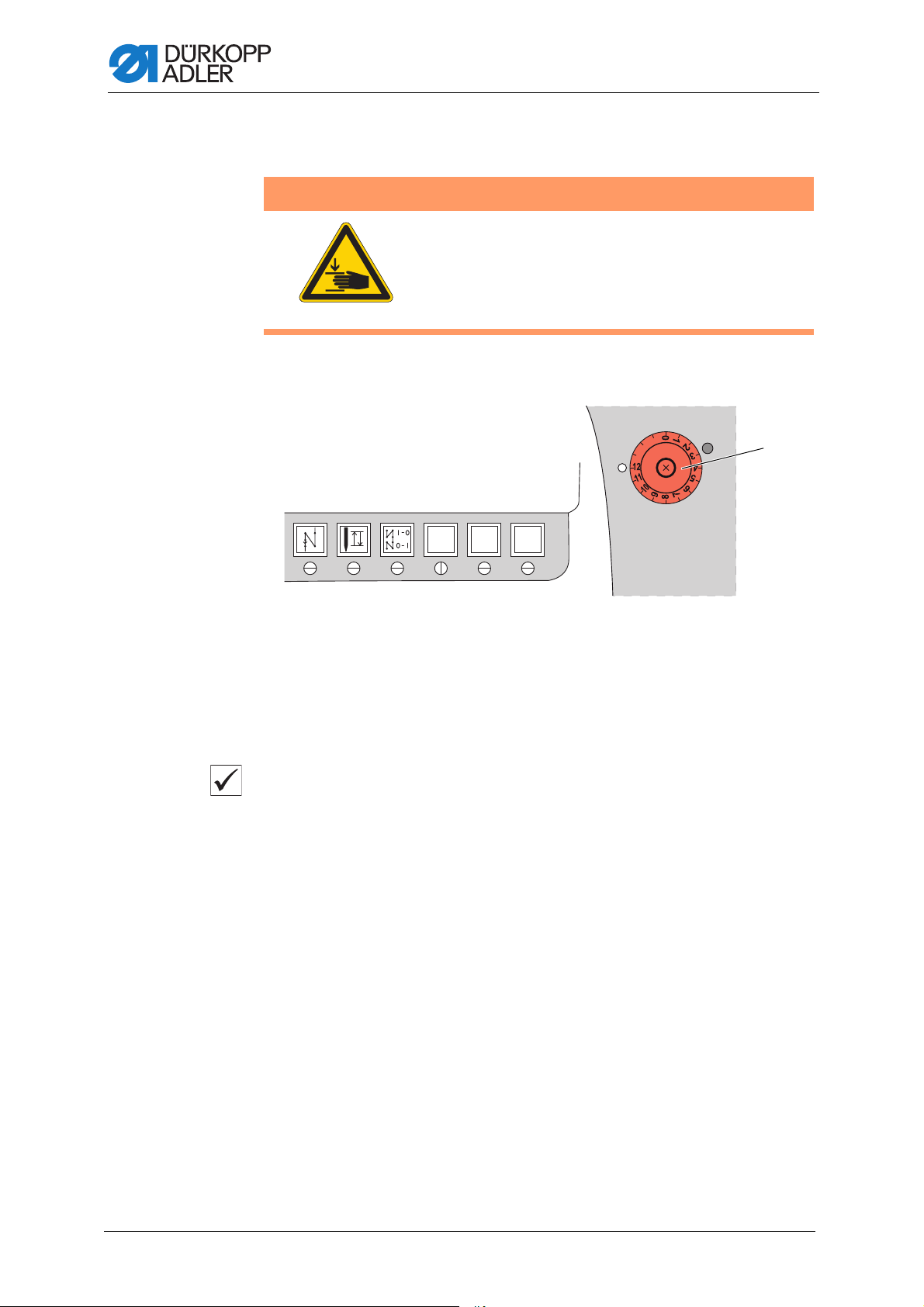
4 Adjusting the handwheel scale ............................................... 25
5 Positioning the arm shaft......................................................... 26
6 Positioning the toothed belt wheels ....................................... 27
6.1 Positioning the upper toothed belt wheel.................................... 27
6.2 Positioning the lower toothed belt wheel .................................... 28
7 Stitch length adjusting wheel.................................................. 30
7.1 Adjusting the stitch length adjusting wheel................................. 30
7.2 Adjusting the stitch length limit ................................................... 32
7.3 Adjusting the eccentric for the forward and backward stitches... 33
8 Needle bar linkage.................................................................... 35
8.1 Aligning the needle bar linkage sideways................................... 35
8.2 Aligning the needle bar linkage in the sewing direction.............. 37
9 Adjusting the feed dog............................................................. 38
9.1 Adjusting the feed dog position .................................................. 38
9.1.1 Moving the feed dog on the feed dog carrier.............................. 38
9.1.2 Moving the feed dog carrier........................................................ 39
9.2 Adjusting the feed dog movement .............................................. 40
9.2.1 Adjusting the feed movement ..................................................... 40
9.2.2 Adjusting the feed dog height at top dead center....................... 41
9.2.3 Adjusting the stroke movement .................................................. 42
9.2.4 Adjusting the compensating weight ............................................ 43
Service Instructions 827/827-M - 01.0 - 05/2019 1
Page 4

Table of Contents
10 Position of the hook and needle ............................................. 44
10.1 Adjusting the looping stroke position.......................................... 44
10.2 Adjusting the hook side clearance.............................................. 46
10.3 Adjusting the needle bar height .................................................. 47
10.4 Adjusting the needle guard......................................................... 48
11 Bobbin case lifter ..................................................................... 50
11.1 Adjusting the lifting gap .............................................................. 51
11.2 Adjusting the timing for opening ................................................. 52
11.3 Adjusting the sewing foot lifting height ....................................... 53
12 Needle thread tension .............................................................. 54
13 Winder ....................................................................................... 55
13.1 Adjusting the winder ................................................................... 55
13.2 Adjusting the hook thread guide ................................................. 58
14 Thread trimmer ......................................................................... 59
14.1 Adjusting the height of the thread-pulling knife........................... 59
14.2 Adjusting the cutoff curve ........................................................... 60
14.3 Adjusting the cutting pressure .................................................... 62
14.4 Adjusting point in time for cutting................................................ 63
15 Puller.......................................................................................... 65
15.1 Adjusting the synchronization of feed dog and puller ................. 66
15.2 Adjusting the distance between carrier roller and needle........... 68
15.3 Adjusting the carrier roller stroke................................................ 69
15.4 Adjusting the carrier roller pressure............................................ 70
15.5 Adjusting the fabric deflector ...................................................... 71
15.6 Adjusting the toothed belt tension .............................................. 72
15.7 Changing the carrier roller .......................................................... 73
16 Adjusting the potentiometer.................................................... 74
17 Safety release clutch................................................................ 76
17.1 Attaching the safety release clutch............................................. 76
17.2 Adjusting the torque.................................................................... 77
18 Integrated motor ....................................................................... 78
18.1 Overview of the components ...................................................... 78
18.2 Disassembling the drive ............................................................. 79
18.2.1 Disassembling the handwheel and handwheel flange................ 79
18.2.2 Disassembling the cover ............................................................ 79
18.2.3 Disassembling the encoder ........................................................ 80
18.2.4 Disassembling the stator ............................................................ 80
18.2.5 Disassembling the rotor .............................................................. 81
18.3 Assembling the drive .................................................................. 82
18.3.1 Assembling the rotor................................................................... 82
18.3.2 Assembling the stator ................................................................. 83
18.3.3 Assembling the encoder ............................................................. 84
18.3.4 Assembling the cover ................................................................. 84
18.3.5 Locking the machine in place ..................................................... 85
18.3.6 Assembling the handwheel flange.............................................. 86
18.3.7 Assembling the handwheel......................................................... 86
2 Service Instructions 827/827-M - 01.0 - 05/2019
Page 5

Table of Contents
19 Programming ............................................................................ 87
19.1 Adjusting the electropneumatic switching of the carrier roller..... 91
19.2 Adjusting the stitch count before the carrier roller is lowered..... 92
20 Maintenance.............................................................................. 93
20.1 Cleaning ..................................................................................... 94
20.1.1 Cleaning the machine................................................................. 95
20.1.2 Cleaning the motor fan mesh ..................................................... 96
20.2 Lubricating .................................................................................. 97
20.2.1 Lubricating the machine head .................................................... 98
20.2.2 Adjusting the hook lubrication..................................................... 99
20.3 Servicing the pneumatic system............................................... 100
20.3.1 Adjusting the operating pressure.............................................. 100
20.3.2 Draining the water condensation .............................................. 101
20.3.3 Cleaning the filter element........................................................ 102
20.4 Checking the toothed belt......................................................... 103
20.5 Parts list.................................................................................... 103
21 Decommissioning................................................................... 105
22 Disposal................................................................................... 107
23 Troubleshooting ..................................................................... 109
23.1 Customer Service ..................................................................... 109
23.2 Messages of the software......................................................... 109
23.2.1 Information messages .............................................................. 109
23.2.2 Error Messages ........................................................................ 113
23.3 Errors in sewing process .......................................................... 115
24 Technical data......................................................................... 117
Service Instructions 827/827-M - 01.0 - 05/2019 3
Page 6

Table of Contents
4 Service Instructions 827/827-M - 01.0 - 05/2019
Page 7

About these instructions
1 About these instructions
These instructions have been prepared with utmost care. They contain
information and notes intended to ensure long-term and reliable operation.
Should you notice any discrepancies or if you have improvement requests,
then we would be glad to receive your feedback through Customer
Service ( p. 109).
Consider these instructions as part of the product and keep it easily
accessible.
1.1 For whom are these instructions intended?
These instructions are intended for:
With regard to minimum qualification and other requirements to be met
by personnel, please also follow the chapter Safety ( p. 9).
• Specialists:
This group has the appropriate technical training for performing
maintenance or repairing malfunctions.
1.2 Representation conventions – symbols and characters
Various information in these instructions is represented or highlighted
by the following characters in order to facilitate easy and quick
understanding:
Proper setting
Specifies proper setting.
Disturbances
Specifies the disturbances that can occur from an incorrect setting.
Cover
Specifies which covers must be disassembled in order to access the
components to be set.
Service Instructions 827/827-M - 01.0 - 05/2019 5
Page 8

About these instructions
1.
2.
…
•
Steps to be performed when operating the machine (sewing and
equipping)
Steps to be performed for service, maintenance, and installation
Steps to be performed via the software control panel
The individual steps are numbered:
First step
Second step
The steps must always be followed in the specified order.
Lists are marked by bullet points.
Result of performing an operation
Change to the machine or on the display/control panel.
Important
Special attention must be paid to this point when performing a step.
Information
Additional information, e.g. on alternative operating options.
Order
Specifies the work to be performed before or after an adjustment.
References
Reference to another section in these instructions.
Safety Important warnings for the user of the machine are specifically marked.
Since safety is of particular importance, hazard symbols, levels of
danger and their signal words are described separately in the chapter
Safety ( p. 9).
Location
information
If no other clear location information is used in a figure, indications of right
or left are always from the user's point of view.
6 Service Instructions 827/827-M - 01.0 - 05/2019
Page 9

About these instructions
1.3 Other documents
The machine includes components from other manufacturers. Each manufacturer has performed a hazard assessment for these purchased parts
and confirmed their design compliance with applicable European and national regulations. The proper use of the built-in components is described
in the corresponding manufacturer's instructions.
1.4 Liability
All information and notes in these instructions have been compiled in
accordance with the latest technology and the applicable standards and
regulations.
Dürkopp Adler cannot be held liable for any damage resulting from:
• Breakage and transport damages
• Failure to observe these instructions
• Improper use
• Unauthorized modifications to the machine
• Use of untrained personnel
• Use of unapproved parts
Transport
Dürkopp Adler cannot be held liable for breakage and transport damages.
Inspect the delivery immediately upon receiving it. Report any damage
to the last transport manager. This also applies if the packaging is not
damaged.
Leave machines, equipment and packaging material in the condition in
which they were found when the damage was discovered. This will ensure
any claims against the transport company.
Report all other complaints to Dürkopp Adler immediately after receiving
the product.
Service Instructions 827/827-M - 01.0 - 05/2019 7
Page 10

About these instructions
8 Service Instructions 827/827-M - 01.0 - 05/2019
Page 11

Safety
2 Safety
This chapter contains basic information for your safety. Read the instructions carefully before setting up or operating the machine. Make sure to
follow the information included in the safety instructions. Failure to do so
can result in serious injury and property damage.
2.1 Basic safety instructions
The machine may only be used as described in these instructions.
These instructions must be available at the machine's location at all times.
Work on live components and equipment is prohibited. Exceptions are
defined in the DIN VDE 0105.
For the following work, switch off the machine at the main switch or
disconnect the power plug:
• Replacing the needle or other sewing tools
• Leaving the workstation
• Performing maintenance work and repairs
• Threading
Missing or faulty parts could impair safety and damage the machine.
Only use original parts from the manufacturer.
Transport Use a lifting carriage or stacker to transport the machine. Raise the
machine max. 20 mm and secure it to prevent it from slipping off.
Setup The connection cable must have a power plug approved in the relevant
country. The power plug may only be assembled to the connection cable
by qualified specialists.
Obligations
of the operator
Follow the country-specific safety and accident prevention regulations and
the legal regulations concerning industrial safety and the protection of
the environment.
All the warnings and safety signs on the machine must always be in legible
condition. Do not remove!
Missing or damaged warnings and safety signs must be replaced
immediately.
Requirements
to be met by
the personnel
Only qualified specialists may:
• Setting up the machine
• Performing maintenance work and repairs
• Performing work on electrical equipment
Only authorized persons may work on the machine and must first have
understood these instructions.
Service Instructions 827/827-M - 01.0 - 05/2019 9
Page 12

Safety
Operation Check the machine during operating for any externally visible damage.
Stop working if you notice any changes to the machine. Report any changes to your supervisor. Do not use a damaged machine any further.
Safety
equipment
Safety equipment should not be disassembled or deactivated. If it is
essential to disassemble or deactivate safety equipment for a repair
operation, it must be assembled and put back into operation immediately
afterward.
2.2 Signal words and symbols used in warnings
Warnings in the text are distinguished by color bars. The color scheme is
based on the severity of the danger. Signal words indicate the severity
of the danger.
Signal words Signal words and the hazard they describe:
Signal word Meaning
DANGER (with hazard symbol)
If ignored, fatal or serious injury will result
WARNING (with hazard symbol)
If ignored, fatal or serious injury can result
CAUTION (with hazard symbol)
If ignored, moderate or minor injury can result
CAUTION (with hazard symbol)
If ignored, environmental damage can result
NOTICE (without hazard symbol)
If ignored, property damage can result
Symbols The following symbols indicate the type of danger to personnel:
Symbol Type of danger
General
Electric shock
10 Service Instructions 827/827-M - 01.0 - 05/2019
Page 13

Safety
Symbol Type of danger
Puncture
Crushing
Environmental damage
Examples Examples of the layout of warnings in the text:
DANGER
Type and source of danger!
Consequences of non-compliance.
Measures for avoiding the danger.
This is what a warning looks like for a hazard that will result in serious
injury or even death if ignored.
WARNING
Type and source of danger!
Consequences of non-compliance.
Measures for avoiding the danger.
This is what a warning looks like for a hazard that could result in
serious or even fatal injury if ignored.
CAUTION
Type and source of danger!
Consequences of non-compliance.
Measures for avoiding the danger.
This is what a warning looks like for a hazard that could result in
moderate or minor injury if the warning is ignored.
Service Instructions 827/827-M - 01.0 - 05/2019 11
Page 14

Safety
CAUTION
Type and source of danger!
Consequences of non-compliance.
Measures for avoiding the danger.
This is what a warning looks like for a hazard that could result in
environmental damage if ignored.
NOTICE
Type and source of danger!
Consequences of non-compliance.
Measures for avoiding the danger.
This is what a warning looks like for a hazard that could result in
property damage if ignored.
12 Service Instructions 827/827-M - 01.0 - 05/2019
Page 15

Working basis
3 Working basis
3.1 Order of the adjustments
Order
The adjustment positions for the machine are interdependent.
Always comply with the order of individual adjustment steps as specified.
It is absolutely essential that you follow all notices regarding prerequisites
and subsequent adjustments that are marked with in the margin.
NOTICE
Property damage may occur!
Risk of machine damage from incorrect order.
It is essential to follow the working order specified in these
instructions.
3.2 Laying the cables
Ensure that all cables are laid in the machine such that the function of
moving parts is not hampered.
To lay the cables:
1. Lay any excess cabling neatly in proper cable snakes.
2. Bind together the cable loops with cable ties.
Important
Tie loops wherever possible to fixed parts.
The cables must be secured firmly.
3. Cut off any overlapping cable ties.
NOTICE
Property damage may occur!
Excess cables can impair the functioning of moving machine parts.
This impairs the sewing function and can result in damage.
Lay excess cable as described above.
Service Instructions 827/827-M - 01.0 - 05/2019 13
Page 16

Working basis
3.3 Removing the covers
WARNING
Risk of injury from sharp and moving parts!
Puncture or crushing possible.
Switch off the machine before removing or
assembling covers.
For many types of adjustment work, you will have to remove the machine
covers first in order to access the components.
This chapter describes how to remove and then assemble the individual
covers again. The text for each type of adjustment work then specifies only
the cover that needs to be removed at that particular time.
3.3.1 Access to the underside of the machine
Cover
To access the components on the underside of the machine, you must tilt
the machine head.
Fig. 1: Access to the underside of the machine
Tilting the machine head
To tilt the machine head:
1. Tilt the machine head as far as it will go.
Erecting the machine head
To erect the machine head:
1. Erect the machine head.
14 Service Instructions 827/827-M - 01.0 - 05/2019
Page 17

Working basis
③
①②
3.3.2 Disassembling and assembling the arm cover
Fig. 2: Disassembling and assembling the arm cover
(1) - Screws
(2) - Arm cover
(3) - Sewing foot stroke adjusting wheel
Disassembling the arm cover
To remove the arm cover:
1. Turn the adjusting wheel for the sewing foot stroke (3) to 2.
2. Loosen the screws (1).
3. Disassemble the arm cover (2).
Assembling the arm cover
To assemble the arm cover:
1. Turn the adjusting wheel for the sewing foot stroke to 2.
2. Assemble the arm cover (2).
3. Tighten the screws (1).
Service Instructions 827/827-M - 01.0 - 05/2019 15
Page 18

3.3.3 Disassembling and assembling the head cover
①
②
Fig. 3: Disassembling and assembling the head cover
Working basis
(1) - Screws (2) - Head cover
Disassembling the head cover
To disassemble the head cover:
1. Loosen the screws (1).
2. Disassemble the head cover (2).
Assembling the head cover
To assemble the head cover:
1. Assemble the head cover (2).
2. Tighten the screws (1).
16 Service Instructions 827/827-M - 01.0 - 05/2019
Page 19

Working basis
②
①
3.3.4 Disassembling and assembling the valve cover
Fig. 4: Disassembling and assembling the valve cover
(1) - Screws (2) - Valve cover
Disassembling the valve cover
To disassemble the valve cover:
1. Loosen the screws (1).
2. Disassemble the valve cover (2).
Important
When disassembling the cover, make sure not to tear off any cables.
Assembling the valve cover
To assemble the valve cover:
1. Assemble the valve cover (2).
2. Tighten the screws (1).
Important
When assembling the cover, make sure not to pinch any cables.
Service Instructions 827/827-M - 01.0 - 05/2019 17
Page 20

3.3.5 Opening and closing the throat plate slide
③
①
②
Fig. 5: Opening and closing the throat plate slide
Working basis
(1) - Throat plate slide
(2) - Throat plate
Opening the throat plate slide
To open the throat plate slide:
1. Press the clamping spring (3) downwards.
2. Push the throat plate slide (1) apart.
Closing the throat plate slide
To close the throat plate slide:
1. Screw the throat plate slide (1) to the throat plate (2).
(3) - Clamping spring
18 Service Instructions 827/827-M - 01.0 - 05/2019
Page 21

Working basis
②③
①
①
3.3.6 Disassembling and assembling the throat plate
Fig. 6: Disassembling and assembling the throat plate
(1) - Screws
(2) - Throat plate
Disassembling the throat plate
To disassemble the throat plate:
1. Open the throat plate slide ( p. 18).
2. Loosen the screws (1).
3. Disassemble the throat plate (2).
Assembling the throat plate
To assemble the throat plate:
1. Insert the throat plate (2).
Ensure that the bobbin case nose (3) is in the cutout of the throat plate.
2. Tighten the screws (1).
3. Close the throat plate slide.
(3) - Bobbin case nose
Service Instructions 827/827-M - 01.0 - 05/2019 19
Page 22

3.3.7 Disassembling and assembling the feed dog
③
②
①
②
WARNING
Risk of injury from sharp and moving parts!
Puncture or crushing possible.
Switch off the machine before you disassemble or
assemble the feed dog.
Fig. 7: Disassembling and assembling the feed dog
Working basis
(1) - Feed dog
(2) - Screws
Disassembling the feed dog
To disassemble the feed dog:
1. Disassemble the throat plate ( p. 19).
2. Loosen the screws (2).
3. Disassemble the feed dog (1) from the feed dog carrier (3).
Assembling the feed dog
To assemble the feed dog:
1. Assemble the feed dog (1) onto the feed dog carrier (3).
2. Tighten the screws (2).
3. Assemble the throat plate ( p. 19).
Important
Check the feed dog position in motion and with the stitch length at its
maximum by turning the handwheel. The feed dog must not hit against
the throat plate.
(3) - Feed dog carrier
20 Service Instructions 827/827-M - 01.0 - 05/2019
Page 23

Working basis
Order
Then check the following adjustment:
• Feed dog ( p. 38)
3.4 Flats on shafts
Fig. 8: Flats on shafts
1
2
(1) - Flat (2) - Shaft
Some shafts have flat surfaces at the points where the components are
screwed on. This stabilizes the connection and makes adjustment easier.
For all adjustments on the surface, the first screw in the direction of
rotation is screwed onto the surface.
Important
Always ensure that the screw faces are completely flush with the surface.
Service Instructions 827/827-M - 01.0 - 05/2019 21
Page 24

Working basis
①②
3.5 Locking the machine in place
For some adjustments, the machine must be locked in place. To do this,
the locking peg (3) from the accessory pack is inserted into a slot on the
arm shaft crank, blocking the arm shaft.
Fig. 9: Locking the machine in place
(3) - Locking opening (3) - Locking peg
Locking the machine in place
To lock the machine in place:
1. Remove the plug from the locking opening (1).
2. Turn the handwheel until the slot is in front of the locking opening (1).
3. Insert the locking peg (2) into the slot.
Removing the lock
To remove the lock:
1. Pull the locking peg (2) out of the slot.
2. Insert the plug into the locking opening (1).
22 Service Instructions 827/827-M - 01.0 - 05/2019
Page 25

Working basis
①
②
3.6 Adjusting the handwheel into position
Fig. 10: Adjusting the handwheel into position
(1) - Graduated scale (2) - Marking
For some adjustments, the graduated scale (1) on the handwheel has to
be moved to a certain position.
To adjust the handwheel into position:
1. Turn the handwheel until the specified number on the graduated
scale (1) is next to the marking (2).
Service Instructions 827/827-M - 01.0 - 05/2019 23
Page 26

Working basis
24 Service Instructions 827/827-M - 01.0 - 05/2019
Page 27

Adjusting the handwheel scale
①
②
4 Adjusting the handwheel scale
Proper setting
1. Lock the machine in place at position 2 ( p. 22).
The handwheel is at position 0°.
If a different degree number is next to the marking (2), then you will
have to reset the graduated scale.
Fig. 11: Adjusting the handwheel scale
(1) - Screw opening (2) - Marking
To adjust the handwheel scale:
1. Lock the machine in place at position 2 ( p. 22).
2. Loosen the fastening screw for the handwheel through the screw
opening (1).
3. Turn the handwheel so that the marking (2) points to the degree
number 0°.
4. Tighten the fastening screw.
5. Turn the handwheel to 50° and tighten the 2
nd
fastening screw.
Service Instructions 827/827-M - 01.0 - 05/2019 25
Page 28

5 Positioning the arm shaft
①
②
③
WARNING
Risk of injury from moving parts!
Crushing possible.
Switch off the machine before you check and set
the position of the arm shaft crank.
Fig. 12: Positioning the arm shaft
Positioning the arm shaft
(1) - Threaded pins
(2) - Machine casting
Proper setting
The 3 threaded pins (1) on the arm shaft crank (3) are seated completely
on the flat. The arm shaft crank (3) is flush with the machine casting (2)
To position the arm shaft:
1. Disassemble the arm cover ( p. 17).
2. Loosen the threaded pins (1).
3. Turn the arm shaft crank (3) such that the threaded pins (1) are seated
completely on the flat of the arm shaft.
4. Push the arm shaft with the arm shaft crank (3) to the right as far as it
will go and flush with the machine casting.
5. Tighten the threaded pins (1).
(3) - Arm shaft crank
26 Service Instructions 827/827-M - 01.0 - 05/2019
Page 29

Positioning the toothed belt wheels
⑤
①
②
③④
6 Positioning the toothed belt wheels
Proper setting
The two toothed belt wheels must be positioned above each other so that
the toothed belt can run correctly. The winder wheel is directly next to the
upper toothed belt wheel and determines its alignment.
Important
The position of the upper toothed belt wheel is defined by the distance to
the winder wheel.
Therefore, you must first align the upper toothed belt wheel on the winder
wheel and then align the lower toothed belt wheel so that the toothed belt
runs correctly over both wheels.
WARNING
Risk of injury from moving parts!
Crushing possible.
Switch off the machine before positioning the
toothed belt wheels.
6.1 Positioning the upper toothed belt wheel
Fig. 13: Positioning the upper toothed belt wheel
(1) - Upper toothed belt wheel
(2) - Threaded pins
(3) - Winder wheel
Proper setting
The 2 threaded pins (2) for the upper toothed belt wheel (1) are seated
flush on the arm shaft (5).
The distance between the winder wheel (3) and the upper toothed belt
wheel (1) must be 0.8 mm.
The toothed belt (4) runs correctly without running against the snap ring or
slipping off.
Service Instructions 827/827-M - 01.0 - 05/2019 27
(4) - Toothed belt
(5) - Flat of arm shaft
Page 30

Positioning the toothed belt wheels
①
②
④
③
To position the upper toothed belt wheel:
1. Disassemble the arm cover ( p. 17).
2. Push the toothed belt (4) sufficiently far to the side so that the
2 threaded pins (2) can be reached.
3. Loosen the threaded pins (2).
4. Turn the upper toothed belt wheel (1) so that the threaded pins(2)
are seated flush on the flat of the arm shaft (5).
5. Move the upper toothed belt wheel (1) to the side so that the distance
to the winder wheel (3) is 0.8 mm.
6. Tighten the threaded pins (2).
7. Push the toothed belt (4) back.
6.2 Positioning the lower toothed belt wheel
Fig. 14: Positioning the lower toothed belt wheel
(1) - Toothed belt
(2) - Snap ring
Proper setting
The 2 threaded pins for the lower toothed belt wheel (3) are seated flush
on the flat of the lower shaft.
The toothed belt (1) runs correctly without running against the snap
ring (2) or slipping off.
To position the lower toothed belt wheel:
1. Tilt the machine head ( p. 14).
2. Loosen the threaded pins (4).
3. Turn the lower toothed belt wheel (3) such that the threaded pins (4)
are seated on the flat of the arm shaft.
(3) - Lower toothed belt wheel
(4) - Threaded pins
28 Service Instructions 827/827-M - 01.0 - 05/2019
Page 31

Positioning the toothed belt wheels
4. Move the lower toothed belt wheel (3) sufficiently far to the side so
that the toothed belt (1) makes contact with the snap ring (2) without
being pushed away.
5. Tighten the threaded pins (4).
Service Instructions 827/827-M - 01.0 - 05/2019 29
Page 32
7 Stitch length adjusting wheel
①
WARNING
Risk of injury from moving parts!
Crushing possible.
Switch off the machine before you set the stitch
length adjusting wheel.
Fig. 15: Adjusting the stitch length adjusting wheel
Stitch length adjusting wheel
(1) - Stitch length adjusting wheel
The stitch length adjusting wheel (1) on the machine column determines
the stitch length.
7.1 Adjusting the stitch length adjusting wheel
Proper setting
1. Adjust the stitch length adjusting wheel to 0.
No play on the stitch regulator gear.
The plates for the gear are parallel; the frame cannot be moved.
30 Service Instructions 827/827-M - 01.0 - 05/2019
Page 33

Stitch length adjusting wheel
③④
⑤
⑥
①
②
⑪
⑧⑨ ⑩
⑦
Fig. 16: Adjusting the stitch length adjusting wheel (1)
(1) - Stitch length adjusting wheel
(2) - Screw
(3) - Wrench
To adjust the stitch length adjusting wheel:
1. Tilt the machine head ( p. 14).
2. Hold the stitch length adjusting wheel (1) in place using the wrench (4).
3. Loosen the screw (2).
4. Remove the stitch length adjusting wheel (1) from the shaft (5).
(4) - Adjusting mark
(5) - Shaft
(6) - Scale
NOTICE
Property damage may occur!
Risk of breakage.
The stitch regulator parts may get stuck, resulting in the maximum
stitch length no longer being achieved.
Do not turn the shaft too far to the right.
5. Carefully turn the shaft (5) clockwise using a 10 mm wrench.
Fig. 17: Adjusting the stitch length adjusting wheel (2)
(7) - Frame for the stitch regulator gear
(8) - Plates for the stitch regulator gear
(9) - Hole
Service Instructions 827/827-M - 01.0 - 05/2019 31
(10) - Screw
(11) - Tension spring
Page 34

Stitch length adjusting wheel
6. Push the stitch regulator to check whether the frame for the stitch
regulator gear (7) can be moved.
7. As soon as the frame of the stitch regulator gear (7) stops moving,
remove the wrench from the shaft (5).
8. Turn the scale (6) so that the 0 is exactly next to the adjusting mark (4).
9. Place the stitch length adjusting wheel (1) onto the shaft (5) and tighten
it with the wrench (3).
Important
10. Check whether the plates for the stitch regulator gear (8) are parallel
to one another.
If the plates of the stitch regulator gear (8) are not parallel to one another:
11. Remove the tension spring (11).
12. Loosen the screw (10).
13. Manually position the plates (8) so that they are parallel.
14. Tighten the screw (10).
15. Attach the tension spring (11).
7.2 Adjusting the stitch length limit
If not all of the stitch lengths are available during sewing operation, a limit
can be placed on the maximum stitch length that can be set.
12, 9, or 6 mm can be selected as the maximum stitch length. The appropriate throat plate must be selected for the selected maximum stitch
length. The throat plate cutout must be large enough to prevent the feed
dog from hitting the edges of the throat plate at the front and rear dead
center.
NOTICE
Property damage may occur!
Risk of damaging the feed dog due to incorrect throat plate size.
Ensure that an appropriate throat plate is used for the selected
maximum stitch length.
Proper setting
Turn the stitch length adjusting wheel clockwise as far as it will go.
The stitch length adjusting wheel can only be turned up to the set
maximum stitch length.
32 Service Instructions 827/827-M - 01.0 - 05/2019
Page 35

Stitch length adjusting wheel
②
③
①
③②
③
④
①
②
Fig. 18: Adjusting the stitch length limit
(1) - Stitch length adjusting wheel
(2) - Screw
To adjust the stitch length limit:
1. Adjust the stitch length adjusting wheel (1) to 0.
2. Hold the stitch length adjusting wheel (1) using a wrench.
3. Loosen the screw (2).
4. Remove the stitch length adjusting wheel (1).
5. Loosen the threaded pin from one of the 3 mark-off openings (3).
6. Screw the threaded pin into the mark-off opening for the required
maximum stitch length. The slots are marked with numbers for the
stitch length.
7. Turn the scale so that the 0 is exactly next to the adjusting mark.
8. Assemble the stitch length adjusting wheel (1) and hold it using a
wrench.
9. Tighten the screw (2).
(3) - Mark-off slots
7.3 Adjusting the eccentric for the forward and backward
stitches
Proper setting
The forward and backward stitches are the same length.
As a test, sew a seam forward, stop, and sew a seam backward. The insertions of the forward and backward stitches have to lie within one another.
Fig. 19: Adjusting the eccentric for the forward and backward stitches
(1) - Block
(2) - Threaded pin
Service Instructions 827/827-M - 01.0 - 05/2019 33
(3) - Eccentric
(4) - Recess
Page 36

Stitch length adjusting wheel
To adjust the eccentric for forward and backward stitches:
1. Tilt the machine head ( p. 14).
2. Loosen the threaded pin (2).
3. Turn the eccentric (3) through the hole.
Initial position
The slot in the eccentric (3) is parallel to the threaded pin (2),
the recess (4) faces the front.
• Turn clockwise: the forward stitch becomes larger, the backward
stitch smaller
• Turn counterclockwise: the forward stitch becomes smaller,
the backward stitch larger
4. Tighten the threaded pin (2).
34 Service Instructions 827/827-M - 01.0 - 05/2019
Page 37

Needle bar linkage
③
④
①
②
8 Needle bar linkage
WARNING
Risk of injury from moving parts!
Crushing possible.
Switch off the machine before aligning the needle
bar linkage.
Proper setting
1. Adjust the stitch length adjusting wheel to 0.
The needle must enter the needle hole precisely in the center.
Order
First, check the following adjustment:
• A straight and undamaged needle has to be inserted ( Operating
Instructions)
8.1 Aligning the needle bar linkage sideways
Fig. 20: Aligning the needle bar linkage sideways (1)
(1) - Threaded pins
(2) - Set collars
To align the needle bar linkage sideways:
1. Disassemble the arm cover ( p. 15).
2. Disassemble the head cover ( p. 16).
3. Adjust the stitch length adjusting wheel to 0.
4. Loosen the threaded pins (1) for the set collars (2).
(3) - Needle hole
(4) - Needle bar linkage
Service Instructions 827/827-M - 01.0 - 05/2019 35
Page 38

Fig. 21: Aligning the needle bar linkage sideways (2)
⑥
⑤
⑥
Needle bar linkage
(5) - Arm shaft crank
(6) - Threaded pins
5. Loosen the threaded pins (6).
Make sure that the threaded pins stay on the surface.
6. Move the needle bar linkage (4) sideways such that the needle pierces
exactly in the center of the needle hole (3).
7. Push the set collars (2) inwards as far as they will go.
8. Tighten the threaded pins (1).
9. Align the thread lever (7) exactly in the middle of the slot.
10. Tighten the threaded pins (6).
Order
Then check the following adjustment:
• Looping stroke position ( p. 44)
• Distance between hook and needle ( p. 44)
(7) - Thread lever
36 Service Instructions 827/827-M - 01.0 - 05/2019
Page 39

Needle bar linkage
④
⑤
①
②
③
8.2 Aligning the needle bar linkage in the sewing direction
Fig. 22: Aligning the needle bar linkage in the sewing direction
126,6 mm
(1) - Arm surface
(2) - Lever
(3) - Center of bolt
Proper setting
1. Adjust the stitch length adjusting wheel to 0.
The lever (2) is positioned so that the distance from the arm surface (1)
to the middle of the bolt (3) is 126.6 mm.
To align the needle bar linkage in the sewing direction:
1. Adjust the stitch length adjusting wheel to 0.
2. Loosen the threaded pins (4).
3. Loosen the screw (5).
4. Position the lever (2).
5. Tighten the threaded pins (4).
6. Tighten the screw (5).
Order
Then check the following adjustment:
• Looping stroke position ( p. 44)
(4) - Threaded pins
(5) - Screw
Service Instructions 827/827-M - 01.0 - 05/2019 37
Page 40

Adjusting the feed dog
③
②
①
②
9 Adjusting the feed dog
WARNING
Risk of injury from moving parts!
Crushing possible.
Switch off the machine before adjusting the feed
dog.
The position and the movement of the feed dog and needle bar have to
be coordinated such that the needle pierces exactly in the center of
the needle hole of the feed dog.
Order
First, check the following adjustment:
• Needle bar linkage( p. 35)
9.1 Adjusting the feed dog position
Proper setting
The feed dog is exactly in the center of the throat plate cutout, both
sideways and in the sewing direction.
If the stitch length is 0, the needle pierces exactly in the center of
the needle hole.
9.1.1 Moving the feed dog on the feed dog carrier
Fig. 23: Moving the feed dog on the feed dog carrier
(1) - Feed dog
(2) - Screws
To move the feed dog on the feed dog carrier:
1. Disassemble the throat plate ( p. 19).
2. Loosen the screws (2).
38 Service Instructions 827/827-M - 01.0 - 05/2019
(3) - Feed dog carrier
Page 41

Adjusting the feed dog
③④ ⑤ ⑥⑤④
①
②
3. Move the feed dog (1) on the feed dog carrier (3).
4. Tighten the screws (2).
9.1.2 Moving the feed dog carrier
Fig. 24: Moving the feed dog carrier
Place the removed throat plate next to it as an aid for orientation so
that the feed dog (1) can be screwed on straight.
(1) - Threaded pins
(2) - Set collars
(3) - Pusher shaft
(4) - Adjusting frame
(5) - Plates
(6) - Screw
The feed dog carrier is connected to the stitch regulator gear via the
pusher shaft and can be moved on this shaft.
To move the feed dog carrier:
1. Tilt the machine head ( p. 14).
2. Adjust the stitch length adjusting wheel to 0.
3. Loosen the threaded pins (1).
4. Loosen the screw (6).
5. Loosen the threaded pins for the set collars (2).
6. Move the feed dog carrier cross-line to the sewing direction such that
the feed dog is exactly in the center of the throat plate cutout.
7. Push the set collars (2) toward each other as far as they will go.
Make sure that the pusher shaft (3) is tightened by the set collars.
8. Tighten the threaded pins for the set collars (2).
9. Tighten the screw (6).
10. Tighten the threaded pins (1).
In the process, make sure that the feed dog height has the proper
setting ( p. 41).
Service Instructions 827/827-M - 01.0 - 05/2019 39
Page 42

Adjusting the feed dog
③
①
②
9.2 Adjusting the feed dog movement
The feed dog moves in an elliptical cycle. To align this correctly, the feed
movement, the feed dog height, and the stroke movement of the feed dog
all have to be set.
Order
First, check the following adjustment:
• Feed dog position ( p. 38)
9.2.1 Adjusting the feed movement
The proper adjustment for the feed movement is checked at standstill
and set using the pusher eccentric.
Fig. 25: Adjusting the feed movement
(1) - Threaded pins
(2) - Pusher eccentric
To adjust the feed movement:
1. Tilt the machine head ( p. 14).
2. Adjust the stitch length adjusting wheel to the maximum stitch length.
3. Loosen the threaded pins (1).
4. Move the handwheel into the 190° position.
5. Press the stitch regulator (3) down and observe how the feed dog
and needle respond.
6. Turn the pusher eccentric (2) so that the feed dog and needle no
longer move when the stitch regulator (3) is pressed.
7. Tighten the threaded pins (1).
(3) - Stitch regulator
40 Service Instructions 827/827-M - 01.0 - 05/2019
Page 43

Adjusting the feed dog
①
②
9.2.2 Adjusting the feed dog height at top dead center
The feed dog reaches the maximum stroke height at top dead center
when the handwheel is positioned at 190°.
Fig. 26: Adjusting the feed dog height at top dead center
(1) - Lever (2) - Threaded pins
Proper setting
1. Place the feed dog at the top dead center by turning the handwheel.
The upper edge of the feed dog protrudes 0.5 mm above the throat
plate.
To adjust the feed dog height at top dead center:
1. Tilt the machine head ( p. 14).
2. Move the handwheel into the 190° position.
3. Loosen the threaded pins (2) on the lever (1) at the left, above the hook.
4. Turn the lever (1) such that the upper edge of the feed dog protrudes
0.5 mm above the throat plate.
5. Tighten the threaded pins (2).
Service Instructions 827/827-M - 01.0 - 05/2019 41
Page 44

9.2.3 Adjusting the stroke movement
②
①
Order
First, check the following adjustment:
• Feed dog height ( p. 41)
Fig. 27: Adjusting the stroke movement
Adjusting the feed dog
(1) - Threaded pins (2) - Stroke eccentric
Proper setting
At the front dead center (handwheel position 90°) and at the rear dead
center (handwheel position 270°) for the feed dog, the upper edge of
the feed dog is at the same height as the upper edge of the throat plate.
At 90°, the feed dog is in the upward movement; at 270°, in the downward
movement.
To adjust the stroke movement:
1. Tilt the machine head ( p. 14).
2. Loosen the threaded pins (1).
3. Move the handwheel into the 90° position.
4. Turn the stroke eccentric (2) such that the upper edge of the feed dog
is at the same height as the upper edge of the throat plate during
the upward movement.
5. Tighten the threaded pins (1).
42 Service Instructions 827/827-M - 01.0 - 05/2019
Page 45

Adjusting the feed dog
③
①
②
9.2.4 Adjusting the compensating weight
Fig. 28: Adjusting the compensating weight
(1) - Threaded pin
(2) - Compensating weight
Proper setting
1. Move the handwheel into the 210° position.
The threaded pin for the compensating weight is parallel to the base
plate.
To adjust the compensating weight:
1. Move the handwheel into the 210° position.
2. Unscrew the threaded pin (1) and leave the allen key inserted in
the threaded pin.
3. Turn the compensating weight (2) such that the threaded pin (1) is
parallel to the base plate (3).
Use the allen key inserted in the threaded pin as a means of orientation.
4. Tighten the threaded pin (1).
(3) - Base plate
Service Instructions 827/827-M - 01.0 - 05/2019 43
Page 46

Position of the hook and needle
10 Position of the hook and needle
WARNING
Risk of injury from moving parts!
Crushing possible.
Switch off the machine before you check and set
the position of the hook and needle.
NOTICE
Property damage may occur!
There is a risk of machine damage, needle breakage or damage
to the thread if the distance between needle groove and hook tip
is incorrect.
Check and, if necessary, reset the distance to the hook tip after
inserting a needle with a new size.
10.1 Adjusting the looping stroke position
The looping stroke is the path length from the bottom dead center of
the needle bar up to the position where the hook tip is exactly on the
vertical center line of the groove for the needle.
The looping stroke is precisely 2 mm.
Order
First, check the following adjustments:
• Needle bar linkage( p. 35)
• A straight and undamaged needle has to be inserted ( Operating
Instructions)
44 Service Instructions 827/827-M - 01.0 - 05/2019
Page 47

Position of the hook and needle
④
①
②③
Fig. 29: Adjusting the looping stroke position
(1) - Threaded pins
(2) - Set collar
Proper setting
1. Lock the machine in place at position 1 ( p. 22).
The hook tip points exactly to the vertical center line of the needle.
Disturbance
• Skip stitches
To adjust the looping stroke position:
1. Tilt the machine head ( p. 14).
2. Disassemble the feed dog ( p. 20).
3. Lock the machine in place at position 1 ( p. 22).
4. Adjust the stitch length adjusting wheel to 0.
5. Loosen all 4 threaded pins (2) for the set collar (1).
6. Turn the hook such that the hook tip (4) points exactly to the vertical
center line of the needle.
7. Tighten the threaded pins (2) for the set collar (1).
Order
(3) - Groove
(4) - Hook tip
Then check the following adjustments:
• Needle guard ( p. 48)
• Timing of cutting by the thread trimmer ( p. 63)
Service Instructions 827/827-M - 01.0 - 05/2019 45
Page 48

Position of the hook and needle
⑤
⑥
③
③④
①
②
10.2 Adjusting the hook side clearance
Order
First, check the following adjustments:
• A straight and undamaged needle has to be inserted ( Operating
Instructions)
• Needle bar linkage( p. 35)
• Looping stroke position ( p. 44)
Fig. 30: Adjusting the hook side clearance
(1) - Threaded pins
(2) - Set collar
(3) - Screws
Proper setting
1. Lock the machine in place at position 1 ( p. 22).
The distance between the hook tip and the groove of the needle is
no greater than 0.1 mm.
To adjust the hook side clearance:
1. Tilt the machine head ( p. 14).
2. Open the throat plate slide ( p. 18).
3. Lock the machine in place at position 1 ( p. 22).
4. Loosen the screws (3).
5. Loosen the threaded pins (1) for the set collar (2).
6. Move the hook support (3) sideways such that the distance between
the hook tip (6) and the groove for the needle (5) is 0.1 mm at most,
without the hook tip (6) touching the needle.
7. Tighten the screws (3).
Order
(4) - Hook support
(5) - Groove
(6) - Hook tip
Then check the following adjustment:
• Needle guard ( p. 48)
46 Service Instructions 827/827-M - 01.0 - 05/2019
Page 49

Position of the hook and needle
①
①
②
④
③
10.3 Adjusting the needle bar height
Order
First, check the following adjustments:
• A straight and undamaged needle has to be inserted ( Operating
Instructions)
• Looping stroke position ( p. 44)
Fig. 31: Adjusting the needle bar height
(1) - Needle bar
(2) - Screw
Proper setting
1. Lock the machine in place at position 1 ( p. 22).
2. Adjust the stitch length adjusting wheel to 0.
The hook tip is level with the lower third of the groove on the needle.
Disturbance
• Damage to the hook tip
• Jamming of the needle thread
• Skip stitches
• Thread breaking
• Needle breakage
To adjust the needle bar height:
1. Disassemble the head cover ( p. 16).
2. Lock the machine in place at position 1 ( p. 22).
3. Adjust the stitch length adjusting wheel to 0.
4. Loosen the screw (2).
5. Move the height of the needle bar (1) such that the hook tip (4) is in
the middle of the lower third of the groove for the needle.
When doing so, take care not to twist the needle to the side.
The groove (3) must face toward the hook.
(3) - Groove
(4) - Hook tip
Service Instructions 827/827-M - 01.0 - 05/2019 47
Page 50

Position of the hook and needle
②
③
①
②
6. Tighten the screw (2).
7. Remove the lock.
Order
Then check the following adjustment:
• Needle guard ( p. 48)
10.4 Adjusting the needle guard
The needle guard prevents contact between needle and hook tip.
Order
First, check the following adjustments:
• Looping stroke position ( p. 44)
• Hook side clearance ( p. 46)
• Needle bar height ( p. 47)
• A straight and undamaged needle has to be inserted ( Operating
Instructions)
Fig. 32: Adjusting the needle guard
(1) - Screw
(2) - Needle guard
Proper setting
1. Lock the machine in place at position 1 ( p. 22).
The needle guard pushes the needle just enough away so that it
cannot be touched by the hook tip.
(3) - Needle
To adjust the needle guard:
1. Disassemble the feed dog ( p. 20).
2. Turn the handwheel and check how far the needle guard (2) pushes
the needle away.
48 Service Instructions 827/827-M - 01.0 - 05/2019
Page 51

Position of the hook and needle
3. Turn the screw (1) such that the needle guard (2) just pushes the
needle (3) far away enough so that it cannot be touched by the hook tip:
• To push away more forcefully: turn counterclockwise
• To push away less forcefully: turn clockwise
Service Instructions 827/827-M - 01.0 - 05/2019 49
Page 52

11 Bobbin case lifter
③
④
①②
WARNING
Risk of injury from moving parts!
Crushing possible.
Switch off the machine before adjusting the bobbin
case lifter.
Fig. 33: Bobbin case lifter
Bobbin case lifter
(1) - Bobbin case lifter
(2) - Bobbin case
The hook pulls the needle thread through between the nose of the bobbin
case (3) and the slot (4) in the throat plate.
The bobbin case lifter (1) now pushes the bobbin case (2) away so that a
gap appears for the thread.
If the hook tip is located below the bobbin case lifter (1), the bobbin case
lifter (1) must open so that the thread can also slide past in that position.
So that the thread can slip through without a problem, the width of the
lifting gap and the timing of opening have to be set.
Disturbance
• Thread breaking
• Formation of loops on the bottom side of the seam
• Loud machine noise
(3) - Nose of the bobbin case
(4) - Slot
50 Service Instructions 827/827-M - 01.0 - 05/2019
Page 53

Bobbin case lifter
③④
①
②
11.1 Adjusting the lifting gap
Fig. 34: Adjusting the lifting gap
(1) - Threaded pin
(2) - Cover
Proper setting
The needle thread slides through unobstructed between the nose of
the bobbin housing and the recess in the throat plate.
To adjust the lifting gap:
1. Tilt the machine head ( p. 14).
2. Open the throat plate slide ( p. 18).
3. Loosen the screw (3).
4. Push the cover (2) downwards.
5. Loosen the threaded pin (1).
6. Adjust the bobbin case lifter such that the gap between the nose of the
bobbin case and the slot in the throat plate is just big enough to allow
the needle thread to slip through without a problem.
While doing so, ensure that the gap is not so big that the middle part
of the hook swings back and forth, hitting the slot in the throat plate.
7. Tighten the threaded pin (1).
8. Push the cover (2) upwards.
9. Tighten the screw (3).
(3) - Screw
(4) - Bobbin case lifter
Service Instructions 827/827-M - 01.0 - 05/2019 51
Page 54

11.2 Adjusting the timing for opening
③
④
②
①
②
Fig. 35: Adjusting the timing for opening
Bobbin case lifter
(1) - Plug
(2) - Hook housing
Proper setting
The bobbin case lifter starts to open exactly at the point when the hook tip
is located below the bobbin case lifter after the loop is taken up.
In 1-needle machines, this happens when the handwheel position is
approx. 100°.
In 2-needle machines, this happens when the handwheel position is
approx. 100° for the right-hand hook, and when the handwheel position is
approx. 300° for the left-hand hook.
For 100° or 300°, the threaded pin of the control cam (4) is exactly in the
middle of the opening. (Insert allen key in the threaded pin for orientation.)
To adjust the timing for opening:
1. Tilt the machine head ( p. 14).
2. Remove the plug (1) on the bottom side of the hook housing (2).
3. Loosen the threaded pin (4) through the opening.
4. Turn the handwheel until the hook tip is exactly below the bobbin case
lifter.
5. Use the allen key to turn the control cam (3) so that the bobbin case
lifter opens at the correct point in time.
6. Tighten the threaded pin (4).
7. Insert the plug (1) into the opening.
(3) - Control cam
(4) - Threaded pin
52 Service Instructions 827/827-M - 01.0 - 05/2019
Page 55

Bobbin case lifter
①
②
11.3 Adjusting the sewing foot lifting height
The adjusting wheel on the machine arm determines how high the presser
foot will be raised during sewing.
WARNING
Risk of injury from moving parts!
Crushing possible.
The machine must remain switched on to allow for
the lifting height of the sewing foot to be set
Do NOT place your hands under the sewing foot
when it is being lowered.
When the pedal is pressed back halfway, the sewing feet can be raised
during sewing, e. g. to move the sewing material.
When the pedal is pressed completely back, the sewing feet will be raised
after the thread is cut so that the sewing material can be exchanged.
Fig. 36: Adjusting the sewing foot lifting height
(1) - Screw (2) - Counternut
To adjust the lifting height of the sewing foot:
1. Loosen the counternut (2) for the adjusting wheel (1).
2. Turn the adjusting wheel (1) to adjust the distance between the raised
sewing feet and the throat plate:
• Raise the sewing feet to a lesser height: turn clockwise
• Raise the sewing feet higher: turn counterclockwise
3. Tighten the counternut (2) for the adjusting wheel (1).
Service Instructions 827/827-M - 01.0 - 05/2019 53
Page 56

Needle thread tension
③
④
①
②
12 Needle thread tension
Adjusting the thread tensioning spring
The thread tensioning spring holds the needle thread under tension from
the top dead center of the thread lever up to the point when the needle eye
plunges into the sewing material.
Fig. 37: Adjusting the thread tensioning spring
(1) - Stop collar
(2) - Spring
Proper setting
Initial position: The thread tensioning spring does not contact the stop
until the needle eye has plunged into the sewing material.
Important
The adjustment for the thread tensioning spring must be varied according
to the sewing material and the required sewing result.
To adjust the thread tensioning spring:
1. Loosen the screw (4).
2. Turn the stop collar (1) to set the spring travel:
• Longer spring travel: turn counterclockwise
• Shorter spring travel: turn clockwise
3. Turn the tension disk (3) to set the spring tension:
• Greater spring tension: turn counterclockwise
• Lower spring tension: turn clockwise
Important
Do not twist the stop collar (1) when doing so.
(3) - Tension disk
(4) - Screw
4. Tighten the screw (4).
54 Service Instructions 827/827-M - 01.0 - 05/2019
Page 57

Winder
③
④
①
②
13 Winder
WARNING
Risk of injury from moving parts!
Crushing possible.
Switch off the machine before adjusting the winder.
13.1 Adjusting the winder
Adjusting the winder filling quantity
Fig. 38: Adjusting the winder filling quantity
(1) - Screws
(2) - Screw
Proper setting
The winder wheel runs smoothly and without axial play.
The winding process will stop automatically when the required filling
quantity of the bobbin is reached.
To adjust the winder filling quantity:
1. Disassemble the arm cover ( p. 15).
2. Loosen the screws (1).
3. Remove the winder.
(3) - Winder lever
(4) - Shank
Service Instructions 827/827-M - 01.0 - 05/2019 55
Page 58

Winder
⑥
③⑧
⑥
⑤
⑤⑨⑩
⑦
The position of the arms (4) on the winder lever (3) determines the filling
quantity:
• Arm (4) parallel: automatic winding stop at 0.5 mm below the edge
of the winder
• Arm (4) closer together: automatic winding stop with larger filling
quantity
• Arm (4) further apart from each other: automatic winding stop with
smaller filling quantity
4. Turn the screw (2):
• Arms (4) closer together: turn counterclockwise
• Arms (4) further apart from each other: turn clockwise
5. Put the completely filled bobbin onto the winder.
6. Fold the winder lever (3) upwards as far as it will go to the thread.
Adjusting the winder spacing
Fig. 39: Adjusting the winder spacing
(3) - Winder lever
(5) - Thread-pulling knife
(6) - Winder spindle
(7) - Right-hand screw hole
To adjust the winder spacing:
1. Turn the winder spindle (6) such that the thread-pulling knife (5) is at
the top right and is facing the right-hand screw hole (7).
2. Loosen the threaded pin in the block (8).
3. Adjust the winder lever (3) so that the distance between the thread on
the bobbin and the winder lever is 2-3 mm.
4. Adjust the block (8) such that it is resting against the locking disk (9).
5. Adjust the block (8) such that its distance to the winder wheel (10) is
0.5 mm.
6. Tighten the threaded pin in the block (8).
(8) - Block
(9) - Locking disk
(10) - Winder wheel
56 Service Instructions 827/827-M - 01.0 - 05/2019
Page 59

Winder
⑪⑫ ⑬ ⑭ ⑬
⑧
⑩
Adjusting the winder run
Fig. 40: Adjusting the winder run
(8) - Block
(10) - Winder wheel
(11) - Thre aded pin
(12) - Threaded pin
(13) - Switch cam
(14) - Leaf spring
To adjust the winder run:
1. Loosen the threaded pin (12).
2. Adjust the switch cam (13) such that it is just contacting the leaf
spring (14) when the block (8) has engaged in the locking disk.
3. Adjust the switch cam (13) such that the winder lever (3) has no axial
play.
4. Tighten the threaded pin (12).
5. Re-assemble the winder.
Service Instructions 827/827-M - 01.0 - 05/2019 57
Page 60

Winder
①②
13.2 Adjusting the hook thread guide
Fig. 41: Adjusting the hook thread guide
(1) - Screw (2) - Hook thread guide
The position of the hook thread guide determines how the hook thread is
wound onto the bobbin.
Proper setting
The hook thread is wound on evenly over the entire width of the bobbin.
To adjust the hook thread guide:
1. Loosen the screw (1).
2. Turn the hook thread guide (2):
• To the front: The hook thread will be wound on further to the front
• To the rear: The hook thread will be wound on further to the rear
58 Service Instructions 827/827-M - 01.0 - 05/2019
Page 61

Thread trimmer
A
③④
⑤
①
②
14 Thread trimmer
WARNING
Risk of injury from sharp and moving parts!
Puncture or crushing possible.
Switch off the machine before adjusting the thread
trimmer.
14.1 Adjusting the height of the thread-pulling knife
The height of the thread-pulling knife is factory-set such that the distance A
between the upper edge of the knife carrier and the hook bearing screw-on
surface is 10.7 +
between the knife carrier and the thread-pulling knife.
0.05 mm. Fine adjustment is made by means of washers
Important
When changing the knives, make sure that you do not lose the washers.
Fig. 42: Adjusting the height of the thread-pulling knife
(1) - Counter blade
(2) - Thread-pulling knife
(3) - Hook bearing screw-on surface
(4) - Knife carrier
(5) - Screw
Proper setting
The thread-pulling knife (2) pivots as close as possible above the hook
and is at the same height as the counter blade (1).
Service Instructions 827/827-M - 01.0 - 05/2019 59
Page 62

Thread trimmer
⑥
⑦
⑧
⑨⑤
③④ ⑤ ③
①
②
To adjust the height of the thread-pulling knife:
1. Open the throat plate slide ( p. 18).
2. Loosen the screw (5).
3. Disassemble the thread-pulling knife (2).
4. Place as many washers between thread-pulling knife (2) and knife
carrier (4) as necessary to ensure that the upper edges of counter
blade (1) and thread-pulling knife (2) are at the same height.
5. Non-required washers on the top side between the thread-pulling
knife (2) and screw (5) should be kept.
6. Tighten the screw (5).
14.2 Adjusting the cutoff curve
Fig. 43: Adjusting the cutoff curve (1)
(1) - Set collar
(2) - Threaded pins
(3) - Control cam
(4) - Threaded pins
(5) - Roller
Proper setting
The control cam (3) makes direct contact with the set collar (1).
The distance between the widest extent (6) of the control cam (3) and
the roller (5) is 0.1 mm at most.
In resting position, the circle mark on the cutting edge of the thread-pulling
knife is exactly next to the tip of the counter blade.
(6) - Widest extent
(7) - Clamping screw
(8) - Lever
(9) - Solenoid
To adjust the cutoff curve:
1. Tilt the machine head ( p. 14).
2. Open the throat plate slide ( p. 18).
3. Loosen the threaded pins (2).
4. Push the set collar (1) as far as it will go to the left.
5. Tighten the threaded pins (2).
60 Service Instructions 827/827-M - 01.0 - 05/2019
Page 63

Thread trimmer
⑬
⑭
⑮
⑩
⑪
⑫
Important
The set collar (1) and control cam (3) are both mutually used as a stop
and must not be loosened at the same time.
Tighten the threaded pins (2) before you loosen the threaded pins (4).
6. Loosen the threaded pins (5).
7. Press the lever (8) against the solenoid (9).
8. Turn the control cam (3) such that its widest extent (6) is at the top,
next to the roller (5).
9. Move the control cam (3) such that the distance between its widest
extent (6) and the roller (5) is 0.1 mm at most.
10. Tighten the threaded pins (4).
11. Loosen the clamping screw (7).
Fig. 44: Adjusting the cutoff curve (2)
(10) - Screw
(11) - Counter blade
(12) - Thread-pulling knife
12. Turn the thread-pulling knife (12) such that the circle mark is exactly
next to the tip of the counter blade (11).
13. Tighten the clamping screw (7) such that the lever (8) has no a xi al pl ay .
14. Loosen the threaded pins (2).
15. Push the set collar (1) to the right as far as it will go and against
the control cam (3).
Important
Check the looping stroke position ( p. 44).
16. Tighten the threaded pins (2).
(13) - Screw
(14) - Hook thread clamp
(15) - Screw
Service Instructions 827/827-M - 01.0 - 05/2019 61
Page 64

Thread trimmer
④
⑤
⑥
①
②
③
14.3 Adjusting the cutting pressure
The shape of the thread-pulling knife automatically creates the required
cutting pressure as soon as the thread-pulling knife and counter blade
make contact.
Fig. 45: Adjusting the cutting pressure
(1) - Screw
(2) - Counter blade
(3) - Thread-pulling knife
Proper setting
In resting position, the hook thread clamp makes contact with the threadpulling knife without any pressure being applied. Any 2 threads with the
greatest strength used for sewing can be neatly cut simultaneously.
Disturbance
• Increased knife wear when the pressure is too great
• Problems when sewing if the hook thread clamp is too high
• Problems in cutting the thread
To adjust the cutting pressure:
1. Open the throat plate slide ( p. 18).
2. Turn the handwheel until the thread-pulling knife (3) can be swung out
by hand.
3. Loosen the screw (1).
4. Position the thread-pulling knife (3) such that the arrow mark is exactly
next to the tip of the counter blade (2).
5. Turn the hook thread clamp (5) such that it rests against the threadpulling knife (3).
6. Turn the counter blade (2) such that it rests against the thread-pulling
knife (3).
7. Tighten the screw (1).
(4) - Screw
(5) - Hook thread clamp
(6) - Screw
Important
Check the position of the cutters, since the counter blade can easily
become warped when the screw is being tightened.
62 Service Instructions 827/827-M - 01.0 - 05/2019
Page 65

Thread trimmer
③
④
⑤⑥
①
②
14.4 Adjusting point in time for cutting
Information
The control cam for the right-hand needle or the right-hand hook support
is identified by an R and an arrow for the direction of rotation.
The control cam for the left-hand needle or the left-hand hook support is
identified by an L and an arrow for the direction of rotation.
Fig. 46: Adjusting point in time for cutting
(1) - Roller
(2) - Set collar
(3) - Control cam
Proper setting
The threads are cut when the thread lever is at the top dead center
(handwheel position 60°).
To adjust the point in time for cutting:
1. Tilt the machine head ( p. 14).
2. Open the throat plate slide ( p. 18).
3. Loosen the threaded pins (6).
4. Turn the handwheel until the thread-pulling knife (4) can be swung out
by hand.
5. Pivot the thread-pulling knife (4) as far forward until the circle mark is
exactly next to the tip of the counter blade (5).
6. Adjust the handwheel position to 60°.
7. Push the control cam (3) to the left as far as it will go and against
the set collar (2).
(4) - Thread-pulling knife
(5) - Counter blade
(6) - Threaded pins
Service Instructions 827/827-M - 01.0 - 05/2019 63
Page 66

Thread trimmer
8. Turn the control cam (3) such that the roller (1) runs up at the contour
of control cam (3) and the widest extent of the control cam is at handwheel position 60° at the highest point.
9. Tighten the threaded pins (6).
10. Check adjustment:
• Insert the thread into thread-pulling knife (4) and slowly turn the
handwheel.
• Check the handwheel position at which the thread is cut.
11. If necessary, repeat adjustment steps 1 – 7 until the cut takes place
at 60°.
64 Service Instructions 827/827-M - 01.0 - 05/2019
Page 67

Puller
15 Puller
CAUTION
Risk of injury from moving parts!
Crushing possible.
Only set the puller when the machine is switched
off.
Fig. 47: Puller
The carrier roller is lifted automatically during the sewing foot lift and
the bartack.
You set the puller at the control panel ( p. 91).
The maximum feed length of the intermittent puller is 7 mm.
Service Instructions 827/827-M - 01.0 - 05/2019 65
Page 68

Puller
①
③
②
20°
15.1 Adjusting the synchronization of feed dog and puller
Proper setting
Feed dog and puller operate in sync.
The movements of carrier roller and feed dog end simultaneously.
The synchronization of feed dog and puller ensures that the sewing
material remains under tension between sewing foot and carrier roller.
This prevents ruffing on the seam during stitch formation.
Fig. 48: Adjusting the synchronization of feed dog and puller
(1) - Small arresting groove
(2) - 1
st
screw in the direction of rotation
(3) - Eccentric
66 Service Instructions 827/827-M - 01.0 - 05/2019
Page 69

Puller
To adjust the synchronization of feed dog and puller:
1. Disassemble the arm cover ( p. 15).
2. Turn the handwheel until the small arresting groove (1) (3 mm) on
the arm shaft crank is pointing up.
In this position, the 1
st
screw in the direction of rotation (2) on the
eccentric (3) is situated in front of the small arresting grove (1) at
approx. 20°.
3. Assemble the arm cover.
4. Check if feed dog and puller are running in sync.
5. Correct the adjustment if feed dog and puller are NOT running in sync.
• Loosen both screws on the eccentric (3)
The eccentric (3) can be turned on the shaft with minimal force.
• Turn the eccentric (3) on the shaft
• Tighten the eccentric (3)
• Assembling the arm cover
• Check if feed dog and puller are running in sync and make
adjustments if necessary
Service Instructions 827/827-M - 01.0 - 05/2019 67
Page 70

Puller
28.5 mm
①
②
15.2 Adjusting the distance between carrier roller and needle
Proper setting
The distance between the middle of the carrier roller and the middle of
the needle is 28.5 mm.
Fig. 49: Adjusting the distance between carrier roller and needle
(1) - Screw (2) - Rocker
To adjust the distance between the carrier roller and needle:
1. Loosen the screw (1).
2. Turn the rocker on the axle (2).
The distance between the middle of the carrier roller and the middle
of the needle is 28.5 mm.
3. Tighten the screw (1).
Order
Proceed by adjusting the carrier roller stroke ( p. 69).
68 Service Instructions 827/827-M - 01.0 - 05/2019
Page 71

Puller
③
①
④
⑤⑥
②
15.3 Adjusting the carrier roller stroke
Proper setting
When in the upper end position, the raised carrier roller must not come
into contact with the sewing foot.
After the carrier roller has been placed on the throat plate, the rocker
must still be deflecting by approx. 1 mm in the lower end position before
the stop of the lever reaches its end position.
Important
If using a steel carrier roller, you need to ensure that there is a still a light
gap in the lower end position. The steel carrier roller must NOT rest on
the throat plate.
Fig. 50: Adjusting the carrier roller stroke
(1) - Rocker
(2) - Bolt
(3) - Threaded pin
To adjust the upper end position:
1. Turn the bolt (2).
The slot of the bolt (2) is parallel to the cylinder axis.
2. Turn the threaded pin (3) to limit the stroke of the cylinder (4).
(4) - Cylinder
(5) - Counternut
(6) - Threaded pin
Service Instructions 827/827-M - 01.0 - 05/2019 69
Page 72

To adjust the lower end position:
①
②
1. Loosen the counternut (5).
2. Turn the threaded pin (6).
• lifting: Turn the threaded pin (6) clockwise
• lowering: Turn the threaded pin (6) counterclockwise
3. Tighten the counternut (5).
15.4 Adjusting the carrier roller pressure
Fig. 51: Adjusting the carrier roller pressure
Puller
(1) - Cylinder (2) - Screw
To adjust the carrier roller pressure:
1. Loosen the screw (2).
2. Move the cylinder (1).
• To reduce pressure: Slide the cylinder (1) to the back
• To increase pressure: Slide the cylinder (1) to the front
3. Tighten the screw (2).
Order
Proceed by adjusting the upper end position of the carrier roller
stroke ( p. 69).
70 Service Instructions 827/827-M - 01.0 - 05/2019
Page 73

Puller
①
②
15.5 Adjusting the fabric deflector
Proper setting
The fabric deflector keeps the sewing material from entering into the slot.
The fabric deflector abuts closely on the carrier roller, leaving just enough
space for the carrier roller to move freely.
Important
If using a steel carrier roller, you need to make sure to remove the fabric
deflector.
Fig. 52: Adjusting the fabric deflecto r
(1) - Fabric deflector (2) - Screw
To adjust the fabric deflector:
1. Loosen the screw (2).
2. Adjust the fabric deflector (1).
The fabric deflector abuts closely on the carrier roller, leaving just
enough space for the carrier roller to move freely.
3. Tighten the screw (2).
Service Instructions 827/827-M - 01.0 - 05/2019 71
Page 74

Puller
①
②
③
④⑥⑤
15.6 Adjusting the toothed belt tension
NOTICE
Property damage may occur!
Malfunctions and excessive wear.
Do not set the toothed belt tension too high.
Proper setting
The toothed belt is tensioned enough to ensure an exact transmission
of the step lengths.
Fig. 53: Adjusting the toothed belt tension
(1) - Lever
(2) - Screw
(3) - Toothed belt
To adjust the upper toothed belt tension:
1. Loosen the screw (2).
2. Move the lever (1) to adjust the tension of the toothed belt (3).
3. Tighten the screw (2).
To adjust the lower toothed belt tension:
1. Loosen the screw (6).
2. Move the lever (4) to adjust the tension of the toothed belt (5).
3. Tighten the screw (6).
72 Service Instructions 827/827-M - 01.0 - 05/2019
(4) - Lever
(5) - Toothed belt
(6) - Screw
Page 75

Puller
①② ③
15.7 Changing the carrier roller
Important
When exchanging a Vulkollan carrier roller for a steel carrier roller, you need
to readjust the lower end position of the carrier roller stroke ( p. 70).
If using a steel carrier roller, you need to make sure to remove the fabric
deflector.
Fig. 54: Changing the carrier roller
(1) - Nut
(2) - Carrier roller
(3) - Axle
To change the carrier roller:
1. Remove the nut (1).
CAUTION: Left-handed thread!
2. Lock the axle (3) with a screw driver.
3. Change the carrier roller (2).
4. Insert the nut (1) and tighten.
Service Instructions 827/827-M - 01.0 - 05/2019 73
Page 76

Adjusting the potentiometer
④
③
⑤①
②
16 Adjusting the potentiometer
WARNING
Risk of injury from moving parts!
Crushing possible.
The machine remains switched on when
the potentiometer is set.
Carry out all work with great caution.
The potentiometer adjusts the s.p.m. to the set sewing foot stroke and
reduces the s.p.m. if the sewing foot stroke is too much.
Proper setting
After accessing the technician level and pressing the OK button, the left
display will show 1 in the first instance and the relevant maximum speed
next to it.
Cover
• Disassemble the arm cover ( p. 15)
Fig. 55: Adjusting the potentiometer (1)
(1) - ESC button
(2) - P button
(3) - Plus/Minus buttons
To adjust the potentiometer:
1. Switch off the machine.
2. Keep the buttons P (2) and Reset (3) pressed down simultaneously
and switch on the machine when doing so.
The display starts.
3. Release the buttons P (2) and Reset (3).
(4) - Reset button
(5) - OK button
The display indicates the current level.
The potentiometer is set at technician level t 10 04.
If the display indicates a different level:
74 Service Instructions 827/827-M - 01.0 - 05/2019
Page 77

Adjusting the potentiometer
②③ ④
①
4. Call up the technician level using the Plus/Minus buttons (3):
As the case may be, press the Plus or Minus button below the letter
or the number until the display indicates t1004.
5. Press the OK (5) button.
Fig. 56: Adjusting the potentiometer (2)
(1) - Threaded pins
(2) - Block
(3) - Threaded pin
(4) - Potentiometer
6. Check whether the lifting gear plates are flush.
If the plates are not flush:
7. Loosen the threaded pins (1).
8. Adjust the connecting clamp (2) for the lifting cylinder such that
the plates are flush.
9. Tighten the threaded pins (1).
10. Loosen the threaded pin (3).
11. Turn the potentiometer axle such that the left display shows 1 in
the first instance and the relevant maximum speed next to it.
12. Tighten the threaded pin (3) without changing the value shown in
the display.
13. Press the ESC button 2 times.
Important
14. Switch off the machine.
15. Switch on the machine.
Switching off and on will save the adjustment.
Service Instructions 827/827-M - 01.0 - 05/2019 75
Page 78

Safety release clutch
①
②③
17 Safety release clutch
WARNING
Risk of injury from moving parts!
Crushing possible.
Switch off the machine before you adjust the safety
release clutch.
The safety release clutch disengages in the event of the thread jamming
and thus prevents the hook from being misadjusted or damaged.
17.1 Attaching the safety release clutch
Fig. 57: Attaching the safety release clutch
(1) - Threaded pins
(2) - Left-hand set collar
Proper setting
The 4 threaded pins (1) on the two set collars next to the safety release
clutch (3) must be parallel to one another. After the safety release clutch
has disengaged, they are no longer parallel.
To latch the safety release clutch:
1. Tilt the machine head ( p. 14).
2. Turn the left set collar (2) such that the threaded pins (1) are parallel
to one another.
The safety release clutch latches into place.
(3) - Safety release clutch
76 Service Instructions 827/827-M - 01.0 - 05/2019
Page 79

Safety release clutch
①
②③ ④
⑤
⑥
⑦
17.2 Adjusting the torque
NOTICE
Property damage may occur!
If you change the torque, it could be that the coupling will not
disengage although this would be required.
This could cause machine damage, e.g. in the event of the thread
jamming.
Do NOT change the factory adjustment.
Make sure that the torque remains at 8 Nm.
Fig. 58: Adjusting the torque
(1) - Threaded pins
(2) - Left-hand set collar
(3) - Safety release clutch
(4) - Right-hand set collar
Proper setting
The machine is set at the factory so that the torque is 8 Nm when
the marking point (6) is exactly above the adjustment slot (5) of the disk.
To adjust the torque:
1. Tilt the machine head ( p. 14).
2. Loosen the screw (7).
3. Using the screw driver, turn the disk on the adjustment slot (5) so that
8 Nm is reached for the torque.
• Increase force: turn in the direction +
• Decrease force: turn in the direction -
4. Tighten the screw (7).
(5) - Adjustment slot
(6) - Marking point
(7) - Screw
Service Instructions 827/827-M - 01.0 - 05/2019 77
Page 80
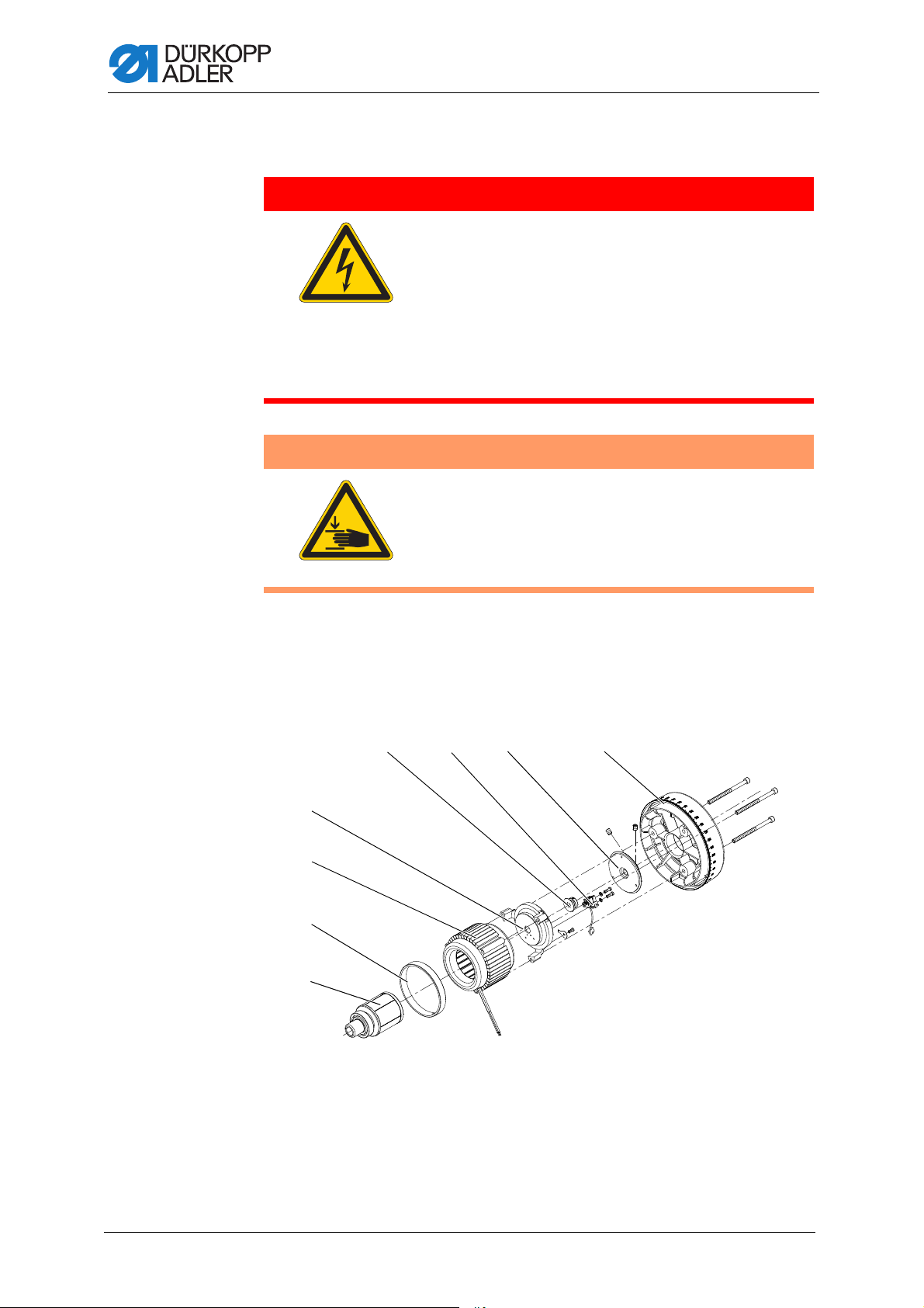
18 Integrated motor
①②③④
⑤
⑥
⑦
⑧
DANGER
Risk of injury from electricity!
Unprotected contact with electricity can result in
serious injuries or death.
Work on the electrical system must ONLY be
carried out by qualified electricians or appropriately
trained and authorized personnel.
ALWAYS pull the power plug before working on
the electrical equipment.
WARNING
Risk of injury from moving parts!
Crushing possible.
Integrated motor
The machine may only be disassembled and
assembled by trained specialists.
18.1 Overview of the components
Fig. 59: Overview of the components
(1) - Handwheel
(2) - Handwheel flange
(3) - Encoder
(4) - Encoder disk
78 Service Instructions 827/827-M - 01.0 - 05/2019
(5) - Cover plate
(6) - Stator
(7) - Ring
(8) - Rotor
Page 81

Integrated motor
①
②
④
③
①
③
①
②
18.2 Disassembling the drive
18.2.1 Disassembling the handwheel and handwheel flange
Fig. 60: Disassembling the handwheel and handwheel flange
(1) - Handwheel
(2) - Screws
To disassemble the handwheel and handwheel flange:
1. Loosen all 3 screws (2) on the handwheel (1).
2. Loosen all threaded pins (3) and disassemble the handwheel
flange (4).
18.2.2 Disassembling the cover
Fig. 61: Disassembling the cover
(3) - Threaded pins
(4) - Handwheel flange
(1) - Screws
(2) - Cover
To disassemble the cover:
1. Loosen all 5 screws (1).
2. Disassemble the cover (2) from the side.
Service Instructions 827/827-M - 01.0 - 05/2019 79
(3) - Handwheel flange
Page 82

18.2.3 Disassembling the encoder
①
②
③
①
②
③
Fig. 62: Disassembling the encoder
Integrated motor
(1) - Encoder disk
(2) - Encoder
To disassemble the encoder:
1. Unscrew the retaining plate (3).
2. Loosen both screws on the encoder (2).
3. Undo the screw on the encoder disk (1).
4. Carefully and uniformly pull the encoder (2) and encoder disk (1)
away from the shaft.
18.2.4 Disassembling the stator
Fig. 63: Disassembling the stator
(3) - Retaining plate
(1) - Stator with ring
(2) - Screws
80 Service Instructions 827/827-M - 01.0 - 05/2019
(3) - Cover plate
Page 83

Integrated motor
①② ③
To disassemble the stator:
1. Loosen the screws (2).
2. Remove the cover plate (3).
3. Remove the stator with ring (1).
18.2.5 Disassembling the rotor
Fig. 64: Disassembling the rotor
(1) - Threaded pins
(2) - Threaded pins
(3) - Rotor with deep groove ball bearing
To disassemble the rotor:
1. Remove the arm cover ( p. 15).
2. Loosen the threaded pins (1), (2).
3. Remove the rotor with deep groove ball bearing (3).
Service Instructions 827/827-M - 01.0 - 05/2019 81
Page 84

18.3 Assembling the drive
①② ③
18.3.1 Assembling the rotor
Fig. 65: Assembling the rotor
Integrated motor
(1) - Threaded pins
(2) - Threaded pins
(3) - Rotor with deep groove ball bearing
To assemble the rotor:
1. Push the rotor with deep groove ball bearing (3) onto the shaft until
the deep groove ball bearing is resting against the stop.
2. Tighten all threaded pins (1), (2) firmly in place, observing the surface
of the shaft in doing so: Tighten the first screw in the direction of rotation
firmly in place on the surface.
82 Service Instructions 827/827-M - 01.0 - 05/2019
Page 85

Integrated motor
①
②
③
18.3.2 Assembling the stator
NOTICE
Property damage may occur!
The stator can be attracted by applying magnetic force.
Work carefully and in a controlled manner.
Fig. 66: Assembling the stator
(1) - Stator with ring
(2) - Screws
To assemble the stator:
1. Push the stator with ring (1) onto the shaft, paying attention to the ring
gap for the cable.
2. Assemble the cover plate (3).
3. Evenly tighten the screws (2) firmly in place so that a uniform gap exists
between the cover plate (3) and shaft.
(3) - Cover plate
Service Instructions 827/827-M - 01.0 - 05/2019 83
Page 86

18.3.3 Assembling the encoder
①
②
③
①
①
②
Fig. 67: Assembling the encoder
Integrated motor
(1) - Encoder disk
(2) - Encoder
To fit the encoder:
1. Push the encoder (2) and encoder disk (1) onto the shaft.
2. Align the encoder disk (1) so that it runs in the middle of the encoder (2).
3. Tighten the encoder disk (1) and encoder (2) firmly in place.
4. Tighten the retaining plate (3).
18.3.4 Assembling the cover
Fig. 68: Assembling the cover
(3) - Retaining plate
(1) - Screws (2) - Cover
To place the cover:
1. Position the cover (2) at the side.
2. Tighten the screws (1).
84 Service Instructions 827/827-M - 01.0 - 05/2019
Page 87

Integrated motor
①
18.3.5 Locking the machine in place
Fig. 69: Locking the machine in place
(1) - Locking peg
To lock the machine in place:
1. Lock the machine in place using the locking peg (1).
The needle is in the top dead center position.
Service Instructions 827/827-M - 01.0 - 05/2019 85
Page 88

18.3.6 Assembling the handwheel flange
①
③
④
②
①
②
Fig. 70: Assembling the handwheel flange
(1) - Handwheel flange marking
(2) - Cover marking
(3) - Threaded pins
(4) - Handwheel flange
Integrated motor
o
To assemble the handwheel flange:
1. Attach the handwheel flange (4) so that the two markings (1), (2) are
in line.
2. Tighten both threaded pins (3) firmly in place.
In doing so, make sure that there is a distance of approx. 0.5 - 1 mm
between the handwheel flange (4) and the cover plate.
18.3.7 Assembling the handwheel
Fig. 71: Assembling the handwheel
(1) - Handwheel (2) - Screws
To assemble the handwheel:
1. Attach the handwheel (1) and tighten all 3 screws (2).
2. Adjust the reference position via the control; see Instructions for
use DAC comfort.
86 Service Instructions 827/827-M - 01.0 - 05/2019
Page 89

Programming
③④ ⑤
②
⑥
⑦①
②
19 Programming
All software settings are performed using the OP1000 control panel.
The control panel is composed of a display and buttons.
Using the control panel you can:
• Use groups of buttons to select machine functions
• Read service and error messages.
Information
This chapter describes the machine-specific functions of the OP1000
control panel.
Refer to the Instructions for use DAC basic/classic for further
information on the control and the OP1000 control panel.
You will find the machine-specific parameters in the parameter list.
Fig. 72: Programming
(1) - Power LED
(2) - Thread button group
(3) - Function button
(4) - Programming button group
(5) - Seam program button group
(6) - LED for 2nd stitch length
(7) - Display
Service Instructions 827/827-M - 01.0 - 05/2019 87
Page 90

OP1000 buttons and functions
Button Function
Thread button group
Start bartack • Sets the start bartack
Multiple start bartack • Sets the multiple start bartack
End bartack • Sets the end bartack
Multiple end bartack • Sets the multiple end bartack
Thread trimmer • Activates or deactivates the thread
Programming
trimmer
Thread clamp • Activates or deactivates the thread
clamp
Needle position after sewing stop • Sets the needle position after sewing
stop
Sewing foot lift after thread
trimmer
Sewing foot lift after sewing stop • Activates or deactivates the sewing
Soft start • Activates or deactivates the soft start
Speed • Reduces the motor speed
Function button • Activates or deactivates any stored
• Activates or deactivates the sewing
foot lift after the thread trimmer
foot lift after sewing stops
function
Programming button group
ESC • Ends parameter mode
88 Service Instructions 827/827-M - 01.0 - 05/2019
Page 91

Programming
Button Function
A+ • Increases parameter
• Changes user level
• Selects subprogram
B+ • Increases parameter
• Changes to next higher category
• Selects subprogram
C+ • Increases parameter
• Selects subprogram
D+ • Increases parameter
• Selects subprogram
OK • Calls parameter or saves it
P • Starts or ends the parameter mode
A- • Decreases parameter
• Changes user level
• Selects subprogram
B- • Decreases parameter
• Changes to next lower category
• Selects subprogram
C- • Decreases parameter
• Selects subprogram
Service Instructions 827/827-M - 01.0 - 05/2019 89
Page 92

Button Function
D- • Decreases parameter
Reset • Resets the (piece) counter
Seam program button group
Seam program I • Activates seam program I
Seam program II • Activates seam program II
Programming
• Selects subprogram
Seam program III • Sets seam program III
90 Service Instructions 827/827-M - 01.0 - 05/2019
Page 93

Programming
19.1 Adjusting the electropneumatic switching of the carrier roller
To adjust the electropneumatic switching of the carrier roller:
1. Press the button.
2. Enter the parameters for the automatic stitch loosening device:
t1400.
•Use A+ to set the value to t.
•Use B+ to set the value to 14.
•Use D+ to set the value to 00.
3. Press the
button.
4. Enter the desired mode:
•Use D+ to enter the value 0: do not raise
•Use D+ to enter the value 1: raise on sewing foot lift
•Use D+ to enter the value 2: raise on bartack
•Use D+ to enter the value 3: raise on bartack and sewing foot lift
5. Press the
button to save the setting.
6. To switch to sewing mode, press the button.
For additional parameter settings, refer to Parameter list.
Service Instructions 827/827-M - 01.0 - 05/2019 91
Page 94

Programming
19.2 Adjusting the stitch count before the carrier roller is lowered
To adjust the stitch count before the carrier roller is lowered:
1. Press the button.
2. Enter the parameters for the s.p.m. before the carrier roller is lowered:
t1403.
3. Use the buttons A+, B+, C+ and D+ to enter the desired s.p.m.
4. Press the
button to save the setting.
5. To switch to sewing mode, press the button.
For additional parameter settings, refer to Parameter list.
92 Service Instructions 827/827-M - 01.0 - 05/2019
Page 95

Maintenance
20 Maintenance
WARNING
Risk of injury from sharp parts!
Punctures and cutting possible.
Prior to any maintenance work, switch off the
machine or set the machine to threading mode.
WARNING
Risk of injury from moving parts!
Crushing possible.
Prior to any maintenance work, switch off the
machine or set the machine to threading mode.
This chapter describes maintenance work that needs to be carried out
on a regular basis to extend the service life of the machine and achieve
the desired seam quality.
Maintenance intervals
Work to be carried out Operating hours
8 40 160 500
Machine head
Removing lint and thread remnants
Cleaning the motor fan mesh
Check the oil level
Check the hook lubrication
Checking the toothed belt
Pneumatic system
Check the water level in the pressure controller
Cleaning the filter element
Service Instructions 827/827-M - 01.0 - 05/2019 93
Page 96

20.1 Cleaning
WARNING
Risk of injury from flying particles!
Flying particles can enter the eyes, causing injury.
Wear safety goggles.
Hold the compressed air gun so that the particles
do not fly close to people.
Make sure no particles fly into the oil pan.
NOTICE
Property damage from soiling!
Lint and thread remnants can impair the operation of the machine.
Clean the machine as described.
Maintenance
NOTICE
Property damage from solvent-based cleaners!
Solvent-based cleaners will damage paintwork.
Use only solvent-free substances for cleaning.
94 Service Instructions 827/827-M - 01.0 - 05/2019
Page 97

Maintenance
①
②
④
③
20.1.1 Cleaning the machine
Lint and thread remnants should be removed after every 8 operating
hours using a compressed air gun or a brush. If very fluffy sewing material
is being sewn the machine must be cleaned more frequently.
Fig. 73: Cleaning
(1) - Area around the needle
(2) - Hook
Areas particularly susceptible to soiling:
• Cutter on the winder for the hook thread (4)
• Area under the throat plate (3)
• Hook (2)
• Area around the needle (1)
To clean the machine:
1. Remove any lint and thread remnants using a compressed air gun
or a brush.
(3) - Area under the throat plate
(4) - Cutter on the winder
Service Instructions 827/827-M - 01.0 - 05/2019 95
Page 98

Maintenance
①
②
20.1.2 Cleaning the motor fan mesh
The motor fan mesh must be cleaned once a month using a compressed
air gun. When very fluffy material is used for sewing, the motor fan mesh
must be cleaned more frequently.
Fig. 74: Cleaning the motor fan mesh
(1) - Tabletop (2) - Motor fan mesh
To clean the motor fan mesh.
1. Remove any lint and thread remnants using a compressed air gun.
96 Service Instructions 827/827-M - 01.0 - 05/2019
Page 99

Maintenance
20.2 Lubricating
CAUTION
Risk of injury from contact with oil!
Oil can cause a rash if it comes into contact with
skin.
Avoid skin contact with oil.
If oil has come into contact with your skin, wash
the affected areas thoroughly.
NOTICE
Property damage from incorrect oil!
Incorrect oil types can result in damage to the machine.
Only use oil that complies with the data in the instructions.
CAUTION
Risk of environmental damage from oil!
Oil is a pollutant and must not enter the sewage
system or the soil.
Carefully collect up used oil.
Dispose of used oil and oily machine parts in
accordance with national regulations.
The machine is equipped with a central oil-wick lubrication system.
The bearings are supplied from the oil reservoir.
For topping off the oil reservoir, use only lubricating oil DA 10 or oil of
equivalent quality with the following specifications:
• Viscosity at 40 °C: 10 mm²/s
• Flash point: 150 °C
You can order the lubricating oil from our sales offices using the following
part numbers:
Container Part no.
250 ml 9047 000011
1 l 9047 000012
2 l 9047 000013
5 l 9047 000014
Service Instructions 827/827-M - 01.0 - 05/2019 97
Page 100

20.2.1 Lubricating the machine head
①
②
③
Fig. 75: Lubricating the machine head
Maintenance
(1) - Oil filler opening
(2) - MAX marking
Proper setting
The oil level must not raise above the MAX marking (2) or drop below
the MIN marking (3).
If the oil level falls below the minimum level marking (3), the oil level
indicator lights up in red.
To top off the oil:
1. Fill oil through the oil filler opening (1) up to the MAX marking (2).
2. Turn the machine off, then on again after refilling oil.
The red light will turn off.
(3) - MIN marking
98 Service Instructions 827/827-M - 01.0 - 05/2019
 Loading...