

Page 1

669 ECO / CLASSIC
Operating Instructions
Page 2

IMPORTANT
READ CAREFULLY BEFORE USE
KEEP FOR FUTURE REFERENCE
All rights reserved.
Property of Dürkopp Adler AG and protected by copyright.
Any reuse of these contents, including extracts, is prohibited without the
prior written approval of Dürkopp Adler AG.
Copyright © Dürkopp Adler AG 2019
Page 3

Table of Contents
1 About these instructions ....................................................................5
1.1 For whom are these instructions intended? .......................................... 5
1.2 Representation conventions – symbols and characters........................6
1.3 Other documents...................................................................................7
1.4 Liability .................................................................................................. 8
2 Safety....................................................................................................9
2.1 Basic safety instructions........................................................................9
2.2 Signal words and symbols used in warnings.......................................10
3 Machine description..........................................................................15
3.1 Components of the machine ...............................................................15
3.2 Proper use...........................................................................................17
3.3 Declaration of Conformity.................................................................... 18
4 Operation ...........................................................................................19
4.1 Preparing the machine for operation ...................................................19
4.2 Inserting or changing the needle.........................................................20
4.3 Threading the needle thread ............................................................... 22
4.4 Winding the bobbin thread .................................................................. 23
4.5 Changing the bobbin ...........................................................................24
4.6 Thread tension ....................................................................................26
4.6.1 Setting the needle thread tension........................................................ 27
4.6.2 Function of the main thread tension and the additional thread
tension depending on the sewing foot lift (optional) ............................29
4.6.3 Function of the additional thread tension depending on the stroke
adjustment and the Speedomat (optional) ..........................................30
4.6.4 Opening the needle thread tension .....................................................31
4.6.5 Switching on and off the supplementary thread tension (optional)......32
4.6.6 Setting the hook thread tension...........................................................33
4.7 Setting the needle thread regulator ..................................................... 34
4.8 Sewing feet.......................................................................................... 35
4.8.1 Lifting the sewing feet.......................................................................... 35
4.8.2 Locking the sewing feet at top dead center .........................................36
4.8.3 Setting the sewing foot pressure.........................................................37
4.8.4 Setting the sewing foot stroke ............................................................. 38
4.9 Setting the stitch length....................................................................... 42
4.10 Buttons on the machine arm ...............................................................43
4.11 Tilting the machine head .....................................................................45
4.12 Folding down the tabletop (optional) ...................................................46
4.13 Sewing.................................................................................................48
4.13.1 Sewing with machines using the F
IR clutch positioning drive ............. 48
4.13.2 Sewing with machines using the Efka DC1550/DA321G
positioning drive ..................................................................................49
Operating Instructions 669 - 00.0 - 08/2019 1
Page 4

Table of Contents
5 Maintenance....................................................................................... 53
5.1 Cleaning .............................................................................................. 54
5.2 Lubricating...........................................................................................56
5.2.1 Checking the oil level in the machine head .........................................57
5.3 Servicing the pneumatic system..........................................................58
5.3.1 Setting the operating pressure ............................................................ 58
5.3.2 Draining the water condensation......................................................... 59
5.3.3 Cleaning the filter element...................................................................60
5.4 Checking the V-belt tension ................................................................ 61
5.5 Parts list...............................................................................................62
6 Setup ..................................................................................................63
6.1 Checking the scope of delivery ...........................................................63
6.2 Removing the transport locks..............................................................63
6.3 Assembling the stand ..........................................................................64
6.3.1 Assembling the stand MG 55-3 ...........................................................64
6.3.2 Assembling the stand MG 56-3 ...........................................................65
6.4 Table top .............................................................................................66
6.4.1 Completing the tabletop for stand MG 55-3 with FIR clutch motor...... 66
6.4.2 Completing the tabletop for stand MG 55-3 with direct drive ..............68
6.4.3 Completing the tabletop for stand MG 56-3 with FIR clutch motor...... 69
6.4.4 Completing the tabletop for stand MG 56-3 with direct drive ..............71
6.4.5 Assembling the tabletop to the stand MG 55-3 ...................................72
6.4.6 Assembling the tabletop to the stand MG 56-3 ...................................73
6.4.7 Assemble support on table plate with cut-out (stand MG 55-3) .......... 74
6.5 Setting the working height ...................................................................75
6.6 Putting on the machine head...............................................................77
6.7 Assembling the operating panel ..........................................................78
6.8 Assembling the sewing light ................................................................79
6.9 Setpoint device for the Direct drive .....................................................81
6.9.1 Assembling the setpoint device to the stand MG 55-3 and aligning
the pedal.............................................................................................. 81
6.9.2 Assembling the setpoint device to the stand MG 56-3 and aligning
the pedal.............................................................................................. 82
6.10 Putting on and tightening the V-belt (clutch motor FIR) ......................83
6.11 Assembling the knee switch ................................................................85
6.12 Assembling the Direct Drive ................................................................ 87
.12.1 Assembling the motor and putting on the V-belt .................................87
6
6.12.2 Connecting the Hall sensor .................................................................88
6.13 Electrical connection ...........................................................................90
6.13.1 Creating the equipotential bonding...................................................... 90
6.13.2 Connecting the clutch motor FIR to the mains voltage........................ 93
6.13.3 Rotational direction of the clutch motor FIR ........................................93
6.13.4 Connecting the sewing light transformator .......................................... 95
2 Operating Instructions 669 - 00.0 - 08/2019
Page 5

Table of Contents
6.13.5 Connecting the DC positioning drive to the mains voltage .................. 96
6.13.6 Rotational direction of the DC positioning drive .................................. 98
6.13.7 Machine-specific parameters ............................................................100
6.13.8 Connecting the sewing light ..............................................................101
6.14 Pneumatic connection .......................................................................102
6.14.1 Assembling the compressed air maintenance unit ............................103
6.14.2 Setting the operating pressure ..........................................................103
6.15 Performing a test run.........................................................................104
7 Decommissioning ...........................................................................105
8 Disposal ...........................................................................................107
9 Troubleshooting .............................................................................. 109
9.1 Customer Service..............................................................................109
9.2 Errors in sewing process ...................................................................110
10 Technical data .................................................................................113
10.1 Data and characteristic values ..........................................................113
10.2 Requirements for trouble-free operation ...........................................113
Operating Instructions 669 - 00.0 - 08/2019 3
Page 6

Table of Contents
4 Operating Instructions 669 - 00.0 - 08/2019
Page 7

About these instructions
1 About these instructions
These instructions have been prepared with utmost care.
They contain information and notes intended to ensure long-term
and reliable operation.
Should you notice any discrepancies or if you have improvement
requests, then we would be glad to receive your feedback through
Customer Service ( p. 109).
Consider the instructions part of the product and store them in a
place where they are readily available.
1.1 For whom are these instructions intended?
These instructions are intended for:
Service Instructions are supplied separately.
With regard to minimum qualification and other requirements to be
met by personnel, please also follow the chapter Safety ( p. 9).
• Operators:
This group is familiar with the machine and has access to
the instructions. Specifically, chapter
Operation ( p. 19) is important for the operators.
•Specialists:
This group has the appropriate technical training for performing maintenance or repairing malfunctions. Specifically, the
chapter Setup ( p. 63) is important for specialists.
Operating Instructions 669 - 00.0 - 08/2019 5
Page 8

About these instructions
1.
2.
...
•
1.2 Representation conventions – symbols and characters
Various information in these instructions is represented or highlighted by the following characters in order to facilitate easy and
quick understanding:
Proper setting
Specifies proper setting.
Disturbances
Specifies the disturbances that can occur from an incorrect setting.
Cover
Specifies which covers must be disassembled in order to access
the components to be set.
Steps to be performed when operating the machine (sewing
and equipping)
Steps to be performed for service, maintenance, and
installation
Steps to be performed via the software control panel
The individual steps are numbered:
First step
Second step
The steps must always be followed in the specified order.
Lists are marked by bullet points.
Result of performing an operation
Change to the machine or on the display/control panel.
Important
Special attention must be paid to this point when performing a step.
6 Operating Instructions 669 - 00.0 - 08/2019
Page 9

About these instructions
Information
Additional information, e.g. on alternative operating options.
Order
Specifies the work to be performed before or after a setting.
References
Reference to another section in these instructions.
Safety Important warnings for the user of the machine are specifically
marked. Since safety is of particular importance, hazard symbols,
levels of danger and their signal words are described separately
in the chapter Safety ( p. 9).
Location
information
If no other clear location information is used in a figure, indications
of right or left are always from the user's point of view.
1.3 Other documents
The machine includes components from other manufacturers.
Each manufacturer has performed a hazard assessment for these
purchased parts and confirmed their design compliance with
applicable European and national regulations. The proper use of
the built-in components is described in the corresponding manufacturer's instructions.
Operating Instructions 669 - 00.0 - 08/2019 7
Page 10

About these instructions
1.4 Liability
All information and notes in these instructions have been compiled
in accordance with the latest technology and the applicable standards and regulations.
Dürkopp Adler cannot be held liable for any damage resulting
from:
• Breakage and damage during transport
• Failure to observe these instructions
• Improper use
• Unauthorized modifications to the machine
• Use of untrained personnel
• Use of unapproved parts
Transport
Dürkopp Adler cannot be held liable for breakage and transport
damages. Inspect the delivery immediately upon receiving it.
Report any damage to the last transport manager. This also
applies if the packaging is not damaged.
Leave machines, equipment and packaging material in the condition in which they were found when the damage was discovered.
This will ensure any claims against the transport company.
Report all other complaints to Dürkopp Adler immediately after
receiving the product.
8 Operating Instructions 669 - 00.0 - 08/2019
Page 11

Safety
2 Safety
This chapter contains basic information for your safety. Read the
instructions carefully before setting up or operating the machine.
Make sure to follow the information included in the safety instructions. Failure to do so can result in serious injury and property
damage.
2.1 Basic safety instructions
The machine may only be used as described in these instructions.
The instructions should be available at the machine's location at
all times.
Work on live components and equipment is prohibited.
Exceptions are defined in the DIN VDE 0105.
For the following work, switch off the machine at the main switch
or disconnect the power plug:
• Replacing the needle or other sewing tools
• Leaving the workstation
• Performing maintenance work and repairs
• Threading
Missing or faulty parts could impair safety and damage the
machine. Only use original parts from the manufacturer.
Transport Use a lifting carriage or forklift to transport the machine. Raise the
machine max. 20 mm and secure it to prevent it from slipping off.
Setup The connecting cable must have a power plug approved in the
relevant country. The power plug may only be assembled to the
power cable by qualified specialists.
Obligations
of the operator
Operating Instructions 669 - 00.0 - 08/2019 9
Follow the country-specific safety and accident prevention regulations and the legal regulations concerning industrial safety and
the protection of the environment.
Page 12

Safety
All the warnings and safety signs on the machine must always be
in legible condition. Do not remove!
Missing or damaged warnings and safety signs must be replaced
immediately.
Requirements
to be met by
the personnel
Only qualified specialists may:
• set up the machine / put the machine in operation
• perform maintenance work and repairs
• perform work on electrical equipment
Only authorized persons may work on the machine and must first
have understood these instructions.
Operation Check the machine during operating for any externally visible
damage. Stop working if you notice any changes to the machine.
Report any changes to your supervisor. Do not use a damaged
machine any further.
Safety
equipment
Safety equipment should not be removed or deactivated. If it is
essential to remove or deactivate safety equipment for a repair
operation, it must be assembled and put back into operation
immediately afterward.
2.2 Signal words and symbols used in warnings
Warnings in the text are distinguished by color bars. The color
scheme is based on the severity of the danger. Signal words
indicate the severity of the danger.
Signal words Signal words and the hazard they describe:
Signal word Meaning
DANGER (with hazard symbol)
If ignored, fatal or serious injury will result
WARNING (with hazard symbol)
10 Operating Instructions 669 - 00.0 - 08/2019
If ignored, fatal or serious injury can result
Page 13
Safety
CAUTION (with hazard symbol)
If ignored, moderate or minor injury can result
CAUTION (with hazard symbol)
If ignored, environmental damage can result
NOTICE (without hazard symbol)
If ignored, property damage can result
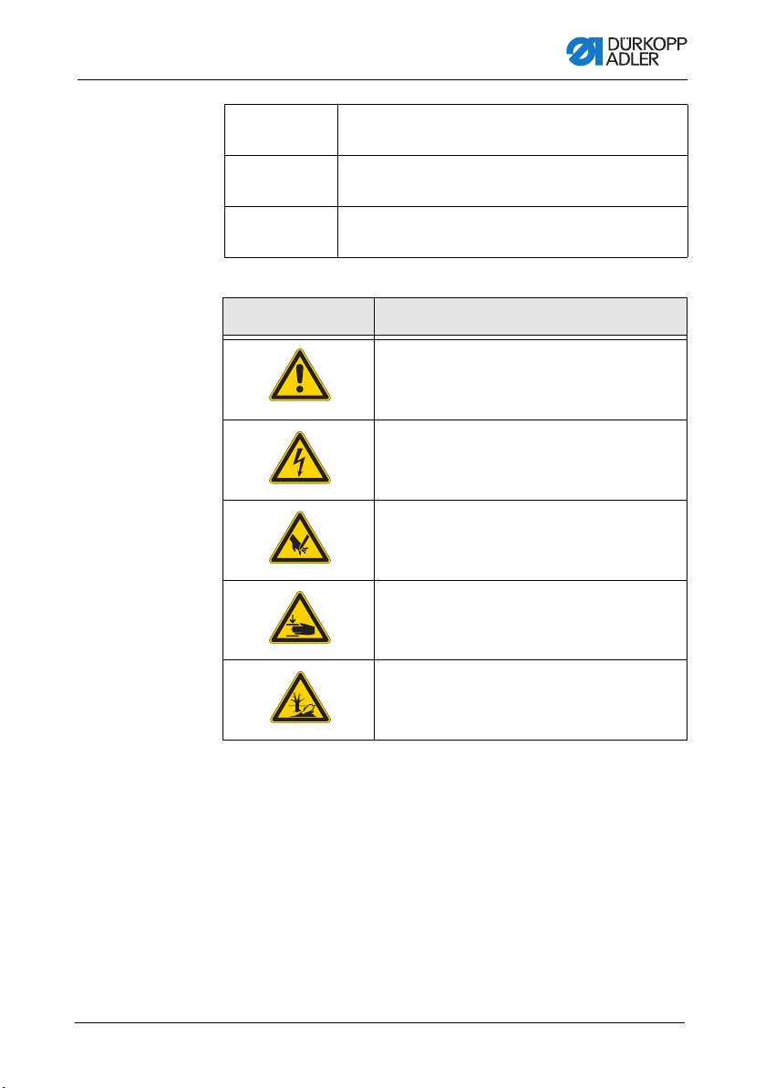
Symbols The following symbols indicate the type of danger to personnel:
Symbol Type of danger
General
Electric shock
Puncture
Crushing
Environmental damage
Operating Instructions 669 - 00.0 - 08/2019 11
Page 14

Examples Examples of the layout of warnings in the text:
DANGER
Type and source of danger!
Consequences of non-compliance.
Measures for avoiding the danger.
This is what a warning looks like for a hazard that will result
in serious injury or even death if ignored.
WARNING
Type and source of danger!
Consequences of non-compliance.
Measures for avoiding the danger.
This is what a warning looks like for a hazard that could
result in serious or even fatal injury if ignored.
Safety
CAUTION
Type and source of danger!
Consequences of non-compliance.
Measures for avoiding the danger.
This is what a warning looks like for a hazard that could
result in moderate or minor injury if the warning is ignored.
12 Operating Instructions 669 - 00.0 - 08/2019
Page 15

Safety
NOTICE
Type and source of danger!
Consequences of non-compliance.
Measures for avoiding the danger.
This is what a warning looks like for a hazard that could
result in property damage if ignored.
CAUTION
Type and source of danger!
Consequences of non-compliance.
Measures for avoiding the danger.
This is what a warning looks like for a hazard that could
result in environmental damage if ignored.
Operating Instructions 669 - 00.0 - 08/2019 13
Page 16

Safety
14 Operating Instructions 669 - 00.0 - 08/2019
Page 17

Machine description
①
②
③
④
⑤
⑥
⑦
3 Machine description
3.1 Components of the machine
Fig. 1: Components of the machine (1), with stand MG 55-3
(1) - Stitch regulator
(2) - Knee switch
(3) - Pedal
(4) - Stand MG 55-3
(5) - Stitch length adjusting wheel
(6) - Reel stand
(7) - Winder
Operating Instructions 669 - 00.0 - 08/2019 15
Page 18

Machine description
①
②
③
④
⑤
⑥
⑦
⑧
⑨
⑩
Fig. 2: Components of the machine (2), with stand MG 56-3
(1) - Operating panel
(2) - Stitch regulator
(3) - Knee switch
(4) - Pedal
(5) - Compressed air maintenance
unit
(6) - Stand MG 56-3
(7) - Control
(8) - Stitch length adjusting wheels
(9) - Reel stand
(10)- Winder
16 Operating Instructions 669 - 00.0 - 08/2019
Page 19

Machine description
3.2 Proper use
WARNING
Risk of injury from live, moving and cutting
parts as well as from sharp parts!
Improper use can result in electric shock, crushing,
cutting and punctures.
Follow all instructions provided.
NOTICE
Non-observance will lead to property damage!
Improper use can result in material damage at the machine.
Follow all instructions provided.
The machine may only be used with sewing material that satisfies
the requirements of the specific application at hand.
The machine is intended only for use with dry sewing material.
The sewing material must not contain any hard objects.
The needle thicknesses permissible for the machine are listed in
the Technical data ( p. 43) chapter.
The seam must be completed with a thread that satisfies the
requirements of the specific application at hand.
The machine is intended for industrial use.
Operating Instructions 669 - 00.0 - 08/2019 17
Page 20

Machine description
The machine may only be set up and operated in dry conditions on
well-maintained premises. If the machine is operated on premises
that are not dry and well-maintained, then further measures may
be required which must be compatible with DIN EN 60204-31.
Only authorized persons may work on the machine.
Dürkopp Adler cannot be held liable for damages resulting from
improper use.
3.3 Declaration of Conformity
The machine complies with European regulations ensuring health,
safety, and environmental protection as specified in the declaration of conformity or in the declaration of incorporation.
18 Operating Instructions 669 - 00.0 - 08/2019
Page 21

Operation
4 Operation
The operating sequence consists of several different steps.
Fault-free operation is necessary in order to achieve a good
sewing result.
4.1 Preparing the machine for operation
WARNING
Risk of injury from moving, cutting and sharp
parts!
Crushing, cutting and punctures are possible.
If possible, make preparations only when the
machine is switched off.
Complete the following steps in preparation of sewing before
starting to work:
• Inserting/changing the needle
• Threading the needle thread
• Inserting and winding on the hook thread
• Setting the thread tension
Operating Instructions 669 - 00.0 - 08/2019 19
Page 22

4.2 Inserting or changing the needle
①
③
②
①②
WARNING
Risk of injury from sharp and moving parts!
Puncture possible.
Switch off the machine bevore changing the
needle.
NOTICE
Property damage may occur!
The insertion of a thinner needle can lead to skipped stitches
or damage to the thread!
The insertion of a thicker needle can result in damage to the
hook tip or the needle!
When switching to a different needle, adjust the clearance
between the hook and the needle.
Fig. 3: Inserting or changing the needle
Operation
(1) - Needle bar
(2) - Screw
20 Operating Instructions 669 - 00.0 - 08/2019
(3) - Groove
Page 23

Operation
To insert or change the needle:
1. Turn the handwheel until the needle bar (1) has reached its
highest position.
2. Loosen screw (2).
3. Pull the needle out from under the needle bar (1).
4. Push in the new needle until it reaches the limit stop in the
hole for the needle bar (1).
Important
The groove (3) must be pointing towards the hoo.
5. Tighten screw (2).
Operating Instructions 669 - 00.0 - 08/2019 21
Page 24

4.3 Threading the needle thread
⑥
⑦
⑧
⑨
⑩
⑪
①
②
③
④
⑤
WARNING
Risk of injury from sharp and moving parts!
Puncture or crushing possible.
Switch off the machine before threading the
needle thread.
Fig. 4: Thrading the needle thread
Operation
(1) - Guide
(2) - Guide
(3) - Pre-tensioner
(4) - Supplementary tensioner
(5) - Main tensioner
(6) - Guide
To thread the needle thread:
1. Put the reel on the reel stand and guide the needle thread
through the thread guide.
The thread guide must be perpendicular to the reel.
22 Operating Instructions 669 - 00.0 - 08/2019
(7) - Guide
(8) - Thread take-u p lev er
(9) - Guide
(10)- Needle thread regulator
(11)- Thread lever
Page 25

Operation
⑤⑥
①②②③④
2. Insert the thread through guide (1) and guide (2).
3. Pass the thread clockwise around the pre-tensioner (3).
4. Pass the thread counter-clockwise around the supplementary
tensioner (4).
5. Pass the thread clockwise around main tensioner (5).
6. Pull the thread under the thread take-up lever (8) and threafd
through the needle thread regulator (10) to the thread
lever (11).
7. Pass the thread through the needle thread lever (11) and
through guides (9) and (6) on the needle bar.
8. Pass the thread through the eye of the needle.
4.4 Winding the bobbin thread
Fig. 5: Winding the bobbin thread
(1) - Winder
(2) - bobbin winder lever
(3) - Guide
To wind the bobbin thread:
(4) - Tensioner
(5) - Guide
(6) - Blade
1. Put the reel on the reel stand. Guide the bobbin thread through
the thread guide.
2. Pull the thread through guide (5), tensioner (4), and guide (3).
3. Clamp the thread behind blade (6) and tear off.
Operating Instructions 669 - 00.0 - 08/2019 23
Page 26
Operation
①②③
4. Put the bobbin on the winder (1).
The thread does not need to be hand wound around the bobbin.
5. Press the bobbin winder lever (2) in the bobbin.
6. Sew.
The bobbin winder lever (2) ends the operation as soon as
the bobbin is full.
The bobbin winder (1) remains in position so that the blade (6)
is properly positioned
7. Take off the full bobbin. Clamp the thread behind the blade (6)
and tear off.
8. Put an empty bobbin on the bobbin winder for the next winding
process and press the bobbin winder lever (2) into the bobbin
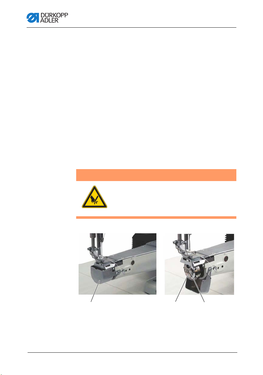
4.5 Changing the bobbin
WARNING
Risk of injury from sharp and moving parts!
Puncture or crushing possible.
Switch off the machine before changing the
bobbin.
Fig. 6: Changing the bobbin (1)
(1) - Hook cover
(2) - Bobbin case retainer
24 Operating Instructions 669 - 00.0 - 08/2019
(3) - Bobbin enclosure
Page 27

Operation
②④⑤
③⑥⑦
To change the bobbin:
1. Raise the needle bar into its high position.
2. Pull out the hook cover (1) and fold dow.
3. Lift up the bobbin case retainer (2).
4. Take out the upper part of the bobbin enclosure (3) with the
bobbin.
5. Remove the empty bobbin from the upper part of the bobbin
enclosure (3).
Fig. 7: Changing the bobbin (2)
(2) - Bobbi n case retainer
(3) - Bobbin enclosure
(4) - Bobbin
(5) - Hole
(6) - Tension spring
(7) - Slot
6. Put a full bobbin in the upper part of the bobbin enclosure (3).
Please note the rotational direction of the bobbin.
The rotation is correct when the bobbin turns in the opposite
direction of the pulling direction of the thread.
7. Pull the hook thread through the slot (7) under the tension
spring (6) and then through the hole (5).
8. Pull out the tension spring (6) from the bobbin enclosure (3)
about 5 cm.
When the thread is being pulled out, the bobbin must rotate
in the direction shown by the arrow.
9. Replace bobbin enclosure (3).
10. Close bobbin case retainer (2).
11. Close the hook cover (1).
Operating Instructions 669 - 00.0 - 08/2019 25
Page 28
Operation
②
①
③
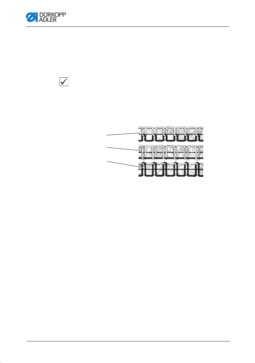
4.6 Thread tension
Together with the hook thread tension, the needle thread tension
influences the final seam pattern. With thin sewing material,
excessive thread tension can lead to undesired gathering and
thread breakage.
Proper setting
If the tension of needle thread and hook thread is identical, the
thread interlacing lies in the middle of the sewing material.
Set the needle thread tension so that the desired seam pattern is
achieved with the lowest possible tension.
Abb. 8: Thread tension
(1) - Iden tical needle thread and hook thread tension
(2) - Hook t hread tension higher than needle thread tension
(3) - Needle thread tension higher than hook thread tension
26 Operating Instructions 669 - 00.0 - 08/2019
Page 29

Operation
①
②③⑤④
4.6.1 Setting the needle thread tension
Fig. 9: Setting the needle thread tension
(1) - Pre-Tensioner
(2) - Main tensioner
(3) - Supplementary tensioner
Pre-tensioner
When the main thread tensioner (2) and the supplementary
tensioner (3) are open, there must still be a slight tension remaining on the needle thread.
This residual tension is created by the pre-tensioner (1).
The pre-tensioner (1) influences both the length of the cut needle
thread and the starter thread for the next seam
To set the basic adjustment:
1. Turn adjusting wheel (4) until its front side is flush with the
bolt (5).
To set a shorter starter thread:
1. Turn the adjusting wheel (4) clockwise.
To set a longer starter thread:
1. Turn the adjusting wheel (4) counter-clockwise.
(4) - Adjusting wheel
(5) - Bolt
Operating Instructions 669 - 00.0 - 08/2019 27
Page 30

Operation
Main tensioner
The main tensioner (2) should be adjusted as little as possible.
The threads’ cross-over point should be in the centre of the material. If the thread tension is too strong, crimping and thread
tearing canoccur when working with a thin material.
To set the main tensioner:
1. Adjust the main tensioner 2 so that you attain a consistent
stitch pattern.
• Increasing the tension: turn the adjusting wheel clockwise
• Decrease the tension: turn the adjusting wheel counterclockwise
Supplementary tensioner
The switchable supplementary tensioner (3) is used for quick
changes to the thread tension (for example, when working with
thicker seams).
To set the supplementary tensioner:
1. The supplementary tension (3) should be set lower than the
main tension (2).
28 Operating Instructions 669 - 00.0 - 08/2019
Page 31

Operation
4.6.2 Function of the main thread tension and the
additional thread tension depending on the
sewing foot lift (optional)
This option applies to the subclass 669-180312.
Button on the machine’s row of buttons can be used to activate
or deactivate the supplementary thread tension at any time. The
parameter F-299 must be set to 1 for this to work. .
Sewing-foot lift in the seam
Parameter
setting
F-196 = 0 0 0 0 0
F-196 = 1 1 1 0 0
F-196 = 2 0 0 1 1
F-196 = 3 1 1 1 1
1 = Thread tension opened mechanicall
0 = Thread tension closed mechanically
Main thread
tension
Supplementary thread
tension
Sewing-foot lift lift after
the thread has been cut
Main thread
tension
Supplementary thread
tension
If the supplementary thread tensioner is open, the state of the
sewing-foot lift does not change
If the machine is turned off, the supplementary thread tension
remains at its previously set state.
Operating Instructions 669 - 00.0 - 08/2019 29
Page 32

Operation
4.6.3 Function of the additional thread tension
depending on the stroke adjustment and the
Speedomat (optional)
This option applies to the subclass 669-180312.
Button on the machine’s row of buttons can be used to activate
or deactivate the supplementary thread tension at any time. The
parameter F-255 must be set to 7 for this to work.
Stroke adjustment via
knee button
Parameter
setting
F-197 = 0 1 1
F-197 = 1 0 1
F-197 = 2 1 (*) 0
F-197 = 3 0 0
(*) If the stroke adjustment (max.) is activated via the knee switch and
the HP speed from parameter F-117 has been reached by the
Speedomat, then the supplementary thread tensioner is automatically
activated.
Max. strike adjustment
via adjusting wheel
when the HP speed from
parameter
F-117 is reached
(Speedomat)
0 = Supplementary thread tension closed mechanicall
1 = Supplementary thread tension opened mechanically
If the supplementary thread tensioner is closed, the state of the
stroke adjustment does not change.
If the machine is turned off, the supplementary thread tension
remains at its previously set state.
30 Operating Instructions 669 - 00.0 - 08/2019
Page 33

Operation
Initial control-box settings for the automatic stepped reduction of
the stitch count (Speedomat), using the adjusting wheel for the
height of the alternating feed stroke:
Parameter 188
Stufe 01-21 Entire Speedomat range
Stufe 01-10 Maximum allowed stitch count, parameter F-111 =
3000 min
Stufe 11-18 Linear step-wise reduction of the maximum stitch count
(Speedomat)
Stufe 19-21 Maximum allowed stitch count, parameter F-117 =
1.800 min
1
1
4.6.4 Opening the needle thread tension
Suibclass 669-180010
When raising the sewing feet by means of the knee lever, the main
and supplementary tensioners are automatically opened.
Subclasses 669-180112, 669-180312
The needle-thread tensioner is automatically opened when the
thread is cut.
Operating Instructions 669 - 00.0 - 08/2019 31
Page 34

Operation
②
①
4.6.5 Switching on and off the supplementary thread
tension (optional)
This option applies to the subclasses 669-180010 and
669-180112.
Fig. 10: Switching on and off the supplementary thread tension
(1) - Leve r (2) - Knob
To switch on and off the supplementary thread tension:
Switch on
1. Push the knob (2) on the lever (1) to the left.
Switch off
1. Push the knob (2) on the lever (1) to the right.
32 Operating Instructions 669 - 00.0 - 08/2019
Page 35

Operation
①
②③
4.6.6 Setting the hook thread tension
WARNING
Risk of injury from sharp and moving parts!
Puncture or crushing possible.
Switch off the machine before setting the hook
thread tension.
Fig. 11: Setting the hook thread tension
(1) - Brak e spring
(2) - Screw
Brake spring
The brake spring (1) is responsible for preventing a bobbin overrun
during a machine stop and when the hook thread is being cut.
It cannot be adjusted!
To set the tension spring:
1. Adjust the tension spring (3) with the screw (2). Turn until the
required tension force is present.
Operating Instructions 669 - 00.0 - 08/2019 33
To increase the hook thread tension:
1. Turn the screw (2) clockwise.
To decrease the hook thread tension:
1. Turn the screw (2) counter-clockwise.
(3) - Tension spring
Page 36

4.7 Setting the needle thread regulator
①②③
Fig. 12: Setting the needle thread regulator
Operation
(1) - Needle thread regulator
(2) - Screw
The neelde thread regulator (1) is used to control the quantity of
the needle thread required by the stitch formation.
The best sewing results can only be ensured when using a precisely adjusted needle thread regulator (1).
At the properly adjusted setting, the needle thread loop must be
able to slide over the thickest section of the hook.
To set the needle thread regulator:
1. Loosen screw (2).
2. Change the position of the needle thread regulator (1).
• Thread regulator to the left: more thread
• Thread regulator to the right: less thread
3. Tighten screw (2).
34 Operating Instructions 669 - 00.0 - 08/2019
(3) - Thread take-up lever
Page 37

Operation
①②
Information
At the point where the most thread is required, the thread take-up
lever (3) must be pulled up about 0.5 mm from its lower end
position.
This occurs when the needle thread loop passes the section of
the hook with the widest diameter.
4.8 Sewing feet
4.8.1 Lifting the sewing feet
Fig. 13: Lifting the sewing feet
(1) - Knee s w itch (2) - Peda l
Subclass 669-180010
The sewing feet can be lifted mechanically by pressing the knee
switch (1).
Subclasses 669-180112, 669-180312
The sewing feet can be lifted electro-pneumatically by pressing
the pedal (2) or the knee switch (1).
Operating Instructions 669 - 00.0 - 08/2019 35
Page 38

Operation
①①
Lifting the sewing feet mechanically (knee switch)
To lift the sewing feet machanically:
1. Push the knee switch (1) to the right in order to move the
sewing material (for example, when making corrections).
The sewing feet remain in the lifted position as long as the
knee switch (1) is pressed.
Lifting the sewing feet electro-pneumatically (pedal)
To lift the sewing feet electro-pneumatically:
1. Press the pedal (2) half way back.
The sewing feet are lifted when the machine is stopped.
2. Press the pedal (2) all the way back.
The thread trimmer will then be activated and the sewing
feet will be lifted.
4.8.2 Locking the sewing feet at top dead center
Fig. 14: Locking the sewing feet at the top dead center
(1) - Lever
To lock the sewing feet at the top dead center:
1. Swivel lever (1) downwards.
The sewing feet are locked at top dead center.
36 Operating Instructions 669 - 00.0 - 08/2019
Page 39

Operation
①
1. Swivel the lever (1) up.
The lock of the sewing feet has been removed.
OR
1. Lift the sewing feet pneumatically using the pedal.
The lever (1) swivels back to its initial position.
4.8.3 Setting the sewing foot pressure
NOTICE
Property damage may occur!
If the sewing foot pressure is too high, the material could
tear.
If the sewing foot pressure is too weak, the material could
slip.
Set the sewing foot pressure in such a way that the sewing
material slides smoothly over the base without slipping.
Fig. 15: Setting the sewing foot pressure
(1) - Adju sting wheel
Operating Instructions 669 - 00.0 - 08/2019 37
Page 40

Operation
①②③
To set the sewing foot pressure:
1. Set the sewing foot pressure using the adjusting wheel (1).
• Increase sewing foot pressure: turn clockwise
• Decrease sewing foot pressure: turn counterclockwise
4.8.4 Setting the sewing foot stroke
NOTICE
Property damage may occur!
It is not possible to set a lower sewing foot stroke on the right
adjusting wheel than on the left adjusting wheel.
Do not attempt to use force to set a smaller sewing foot
stroke on the right adjusting wheel.
Fig. 16: Setting the sewing foot stroke (1)
(1) - Adju sting wheel
(2) - Adju sting wheel
(3) - Knee switch
Use the adjusting wheel (2) on the left to select the standard
sewing foot stroke from1 to 9.
Use the adjusting wheel (1) on the right to set a higher sewing foot
stroke from 1 to 9.
38 Operating Instructions 669 - 00.0 - 08/2019
Page 41

Operation
To set the sewing foot stroke:
1. Turn adjusting wheel (1) and (2) (from 1 to 9).
• 1: minimal sewing foot stroke
• 9: maximum sewing foot stroke
Automatic stitch rate limit
Machines without a thread trimmer
The speed is not verified on these machines.
Machines with a thread trimmer
The sewing-foot stroke and stitch count are interdependent. A
potentiometer is connected mechanically with the adjusting wheel.
The control unit detects what foot-stroke has been set by means
of this potentiometer and restricts the speed of rotation accordingly.
Machines with electro-pneumatic rapid stroke adjustment
When processing thick sections of material or when sewing over
transversal seams, the higher sewing-foot stroke (adjusting
wheel (1)) can be activated while sewing by means of the knee
switch (3) (under the table plate).
A potentiometer is used here just as in the machines with thread
trimmers.
Operating mode for the rapid stroke adjustment
The activation time for the maximum sewing-foot stroke depends
on which operating mode is set. You can select between three
different operating modes.
Operating Instructions 669 - 00.0 - 08/2019 39
Page 42

Operation
③
④
The particular modes are specified on the operating panel by
setting the parameters F-138 a nd F-184 (refer to the instructions
from the motor manufacturer).
Operating
mode
momentary
contact
F-138 = 0
F-184 = 0
maintained
contact
F-138 = 1
momentary
contact with
minimum
stitch count
F-138 = 0
F-184 0 < 100
Operation/Explanation
The maximum sewing-foot stroke remains activated as
long as the knee switch is being pressed.
The maximum sewing-foot stroke is activated when the
knee switch is pressed.
Pressing the knee switch again will then deactivate the
maximum sewing-foot stroke.
The maximum sewing-foot stroke remains activated as
long as the knee switch is being pressed.
After releasing the knee switch, the machine continues
to sew with the maximum sewing-foot stroke until the
specified minimum stitch count (parameter F-184) is
reached. Afterwards, sewing continues with the standard sewing-foot stroke.
Information
Fig. 17: Setting the sewing foot stroke (2)
(3) - Knee switch (4) - Switch
The switch (4) on the rear of the knee switch (3) can also be used
to switch between the maintained contact and momentary contact
modes.
40 Operating Instructions 669 - 00.0 - 08/2019
Page 43

Operation
Maximum stitch count
Stitch length range
adjusting wheel
position
0 - 6 1 - 3
6 - 9 1 - 4
Sewing foot stroke
[mm]
4
5
6 - 9
5
6 - 9
max. stitch count
-1
]
[min
3000
2500
2100
1800
2500
2100
1800
Important
Do not exceed the max. stitch count limits specified in the table.
Observing these limits will ensure safe operations and a long
lifespan for the machine.
Operating Instructions 669 - 00.0 - 08/2019 41
Page 44

4.9 Setting the stitch length
①②③④
NOTICE
Property damage may occur!
It is not possible to set a lower stitch length on the upper
adjusting wheel than on the lower adjusting wheel.
Do not attempt to force the top adjusting wheel to set a lower
stitch length.
Fig. 18: Setting the stitch length
Operation
(1) - Adju sting wheel
(2) - Adju sting wheel
(3) - Stitch regulator
(4) - Button
The machine is equipped with two adjusting wheels, depending
on the subclass. This allows two different stitches to be used when
sewing. They can be selected using button 4 ( p. 43).
The stitch lengths are set using the adjusting wheels (1) and (2)
on the machine arm.
To set the stitch length:
1. Set the longer stitch length with the upper adjusting wheel (1).
• Position 1: min. stitch length
• Position 9: max. stitch length
2. Set the shorter stitch length with the lower adjusting wheel (2).
• Position 1: min. stitch length
• Position 9: max. stitch length
42 Operating Instructions 669 - 00.0 - 08/2019
Page 45

Operation
⑦
⑧
①②③④⑤⑥
Stitch lengths are equal for both forward and reverse sewing.
3. Push the stitch regulator (3) down in order to manually sew
bartacks.
The machine will sew backwards as long as the stitch
regulator (3) is pressed down
Information
in order to facilitate the process of adjusting the stitch lengths, the
button (4) should be used to fix the stitch lengths so that they do
not shift.
4.10 Buttons on the machine arm
Fig. 19: Buttons on the machinearm
(1) - Button supplementary thread
tension
(2) - Button 2. stitch length
(3) - Butt on start/final bartack
(4) - Butt on needle position
Operating Instructions 669 - 00.0 - 08/2019 43
(5) - Button sew backwards
(6) - Screw
(7) - Key
(8) - LED
Page 46

Taste Funktion
Operation
①
②
③
④
⑤
Supplementary tread tension
Button is back-lit:
the supplementary thread tension is activated.
Button is not back-lit:
the supplementary thread tension is not activated.
2. stitch length
Button is back-lit:
long stitch length (upper adjusting wheel) is activated
Button is not back-lit:
small stitch length (lower adjusting wheel) is activated
Invoke or suppress the start/final bartacks.
If the start and final bartacks are activated, then the
next bartack is deactivated when the button is pressed.
If the start and final bartacks are not activated, then the
next bartack is activated when the button is pressed.
Move the needle to the upper or lower position. The
function of the button can be set with the parameter
F-242.
1 = needle up/down
2 = needle up
3=singlestitch
4 = full stitch
5 = needle to position 2
The factory default setting is 1 (needle up/down
Sew backwards manually
The machine sews backwards for as long as the button
is held down.
⑧
LED display Power On
The key (7) can be assigned a function using the screw (6)( found
under the switch.
1. Select a function.
For example: 6 = sew backwards manually.
2. Press in the screw under key (5) and turn 90° to the right (the
slot is vertical).
This function can now be activated using either key (5)
or (7).
44 Operating Instructions 669 - 00.0 - 08/2019
Page 47

Operation
①③ ②
4.11 Tilting the machine head
WARNING
Risk of injury from moving parts!
Crushing possible.
DO NOT reach between base and machine arm
when tilting the machine head.
NOTICE
Property damage may occur!
Oil leakage possible.
Tilt the machine head only briefly.
Fig. 20: Tilting the machine head
(1) - Lever
(2) - Strap
To tilt the machine head:
1. Press lever (1) upwards.
The locking mechanism is then released.
(3) - Machine head
Operating Instructions 669 - 00.0 - 08/2019 45
Page 48

Operation
①
①②
2. Tilt the machine head (3) to the rear
The machine head (3) will be supported by the strap (2).
To erect the machine head:
1. Tilt the machine head (3) forwards.
2. Pull lever (1) back up.C
3. Carefully tilt the machine head (3) downwards
4.12 Folding down the tabletop (optional)
This option applies to the stand MG 56-2.
WARNING
Risk of injury from moving parts!
Crushing possible.
Hold the table top with both hands when pulling it
off.
Fig. 21: Folding down the tabletop (1)
(1) - Tabl etop latch (2) - Tabl etop
To fold down the tabletop:
1. Loosen the tabletop latch (1) located under the tabletop (2).
46 Operating Instructions 669 - 00.0 - 08/2019
Page 49

Operation
③④
2. Pull out the tabletop (2) to the left and fold out.
Fig. 22: Folding down the tabletop (2)
(3) - Bolt (4) - Diagonal brace
3. Hook in the diagonal brace (4) to the bolt (3).
4. Fold down the tabletop (2).
Follow these steps in the opposite order to raise the table plate.
Operating Instructions 669 - 00.0 - 08/2019 47
Page 50

Operation
4.13 Sewing
4.13.1 Sewing with machines using the FIR clutch
positioning drive
Fig. 23: Sewing with machines using the FIR clutch positioning drive
(0) - At rest
(1) - Sewing forwards with minimum speed
(2) - Sewing forwards with higher speed
(3) - Sewing forwards with maximum speed
You can find a comprehensive description of the control unit in
the current operating instructions from the motor manufacturer.
48 Operating Instructions 669 - 00.0 - 08/2019
Page 51

Operation
4.13.2 Sewing with machines using the Efka DC1550/
DA321G positioning drive
The DA321G control unit contains all required operational interfaces for switching functions and setting parameters.
It is possible to operate without an operating panel, but the seam
programming can no longer be carried out.
The V810 and V820 operating panels can also be connected to
the control unit. They are deliverable as accessories.
Seam programming can be performed with the V820 operating
panel.
The EFKA DC1550 – DA321G Operating Manual contains a more
detailed description of the control unit (also refer to
www.efka.net).
Fig. 24: Sewing with machines using the Efka DC1550/DA321G positioning drive (1)
Pedal
position
-2 Completely back-
-1 Half backwards Command for raising the sewing foot
0 Neutral rest posi-
1 Slightly forwards Command for lowering the sewing foot
2 More forwards Sew with miminal speed (first level)
3 More forwards Sew with more speed (second level)
13 Entirely forwards Sew with maximal speed (twelfth level)
Operating Instructions 669 - 00.0 - 08/2019 49
Pedal movement Function
Command for cutting the thread (end of
wards
tion
seam)
Page 52

Operation
①②③④
Information
The following functions can be programmed to correspond with
the rest position:
• Needle position (down/up) and sewing-foot position (down/up)
when stop in seam
• Sewing-foot position (up/down) after end of seam
Fig. 25: Sewing with machines using the Efka DC1550/DA321G positioning drive (2)
(1) - Button supplementary thread
tension
(2) - Button 2. stitch length
Sewing
Sewing process Operation
Before sewing start
Starting position • Pedal in resting position
Position material at
seam start
Sewing • Press the pedal forward and hold
50 Operating Instructions 669 - 00.0 - 08/2019
The machine is at rest
The needle is up
The sewing feet are down
• Move pedal back halfway
The sewing feet lift
• Push the material to the needle
The machine then continues to sew with the
speed determined by the pedal
(3) - Button sew backwards
(4) - Stitch regulator
Page 53

Operation
Sewing process Operation
In the middle of the
seam
Interrupt sewing
operation
Continue sewing
operation (after
releasing the pedal)
Sewing an intermediate lockstitch
Sewing over transverse seams (maximum sewing-foot
stroke)
nd
set stitch length
2
during sewing
(max. stitch length)
Raise the thread
tension during
sewing
• Release pedal (return to rest position)
The machine stops in the first position (needle
down)
The sewing feet are down
• Press the pedal forward
The machine then continues to sew with the
speed determined by the pedal
• Press the stitch regulator (4) downwards.
The machine sews in reverse as long as the
stitch regulator (4) is pressed.
The speed is determined by the pedal.
OR
• Press button (3)
The maximum sewing-foot stroke is activated.
-1
The speed is limited to 1600 min
.
Operating modes for maximum sewing-foot
stroke
• Briefly press the knee switch for activating the
maximum sewong foot stroke
• Briefly press the knee switch again for deactiva-
ting the maximum sewing foot switch
• Press the button (2)
• Press the button (1)
At seam end
Remove sewing
materia
• Press the pedal completely backwards and
hold
The final bartack is sewn (when activated).
The thread is cut.
The machine stops in the second position.
The needles are up (reverse rotation). T
he sewing feet are down.
• Take out the material
Operating Instructions 669 - 00.0 - 08/2019 51
Page 54

Operation
52 Operating Instructions 669 - 00.0 - 08/2019
Page 55

Maintenance
5 Maintenance
WARNING
Risk of injury from sharp parts!
Punctures and cutting possible.
Prior to any maintenance work, switch off the
machine or set the machine to threading mode.
WARNING
Risk of injury from moving parts!
Crushing possible.
Prior to any maintenance work, switch off the
machine or set the machine to threading mode.
This chapter describes maintenance work that needs to be carried
out on a regular basis to extend the service life of the machine
and achieve the desired seam quality.
Advanced maintenance work may only be carried out by qualified
specialists ( Service Instructions).
Maintenance intervals
Work to be carried out Operating hours
8 40 160 500
Removing lint and thread remnants
Cleaning the motor fan sieve
Servicing the pneumatic system
Checking the V-belt tension
Operating Instructions 669 - 00.0 - 08/2019 53
Page 56

5.1 Cleaning
WARNING
Risk of injury from flying particles!
Flying particles can enter the eyes, causing injury.
Wear safety goggles.
Hold the compressed air gun so that the particles
do not fly close to people.
Make sure no particles fly into the oil pan.
NOTICE
Property damage from soiling!
Lint and thread remnants can impair the operation of the
machine.
Clean the machine as described.
NOTICE
Maintenance
Property damage from solvent-based cleaners!
Solvent-based cleaners will damage paintwork.
Use only solvent-free substances for cleaning.
54 Operating Instructions 669 - 00.0 - 08/2019
Page 57

Maintenance
②① ③
Fig. 26: Cleaning
(1) - Hook
(2) - Area under the throat plate
(3) - Motor fan sieve
Points that need to be cleaned particularly thoroughly:
• Area under the throat plate (2)
• Area around the hook (1)
• Bobbin case
• Thread cutter
• Area around the needle
• Motor fan sieve (3)
To clean the machine:
1. Blow out dust and thread residues with the compressed air
gun.
Operating Instructions 669 - 00.0 - 08/2019 55
Page 58

Maintenance
5.2 Lubricating
CAUTION
Risk of injury from contact with oil!
Oil can cause a rash if it comes into contact with
skin.
Avoid skin contact with oil.
If oil has come into contact with your skin, wash
the affected areas thoroughly.
NOTICE
Property damage from incorrect oil!
Incorrect oil types can result in damage to the machine.
Only use oil that complies with the data in the instructions.
CAUTION
Risk of environmental damage from oil!
Oil is a pollutant and must not enter the sewage
system or the soil.
Carefully collect up used oil.
Dispose of used oil and oily machine parts in
accordance with national regulations.
The machine is equipped with a central oil-wick lubrication system.
The bearings are supplied from the oil reservoir.
For topping off the oil reservoir, use only lubricating oil DA 10 or
oil of equivalent quality with the following specifications:
• Viscosity at 40 °C:10 mm2/s
• Flash point: 150 °C
56 Operating Instructions 669 - 00.0 - 08/2019
Page 59

Maintenance
②
③
①
④
You can order the lubricating oil from our sales offices using the
following part numbers.
Container Part no.
250 ml 9047 000011
1 l 9047 000012
2 l 9047 000013
5 l 9047 000014
5.2.1 Checking the oil level in the machine head
Fig. 27: Checking the oil level in the machine head
(1) - Oil reservoir
(2) - Hole
Proper setting
The oil level must not raise above the MAX marking (4) or drop
below the MIN marking (3).
To top off the oil:
(3) - MIN marking
(4) - MAX marking
1. Fill oil through the hole (2) up to the MAX marking (4).
Operating Instructions 669 - 00.0 - 08/2019 57
Page 60

Maintenance
②
①
5.3 Servicing the pneumatic system
5.3.1 Setting the operating pressure
NOTICE
Property damage from incorrect setting!
Incorrect operating pressure can result in damage to the
machine.
Ensure that the machine is only used when the operating
pressure is set correctly.
Proper setting
Refer to the Technical data ( p. 43) chapter for the permissible
operating pressure. The operating pressure cannot deviate by
more than ± 0.5 bar.
Check the operating pressure on a daily basis.
Fig. 28: Setting the operating pressure
(1) - Pres sure controller (2) - Pressure gage
To set the operating pressure:
1. Pull the pressure controller (1) up.
58 Operating Instructions 669 - 00.0 - 08/2019
Page 61

Maintenance
①
③
②
2. Turn the pressure controller until the pressure gage (2)
indicates the proper setting:
• Increase pressure = turn clockwise
• Reduce pressure = turn counterclockwise
3. Push the pressure controller (1) down.
5.3.2 Draining the water condensation
NOTICE
Property damage from excess water!
Excess water can cause damage to the machine.
Drain water as required.
Water condensation accumulates in the water separator (2) of the
pressure controller.
Proper setting
Water condensation must not rise up to the level of the filter
element (1).
Check the water level in the water separator (2) on a daily basis.
Fig. 29: Draining the water condensation
(1) - Filter element
(2) - Water separator
Operating Instructions 669 - 00.0 - 08/2019 59
(3) - Drain screw
Page 62

Maintenance
①
③
②
To drain water condensation:
1. Disconnect the machine from the compressed air supply.
2. Place the collection tray under the drain screw (3).
3. Loosen the drain screw (3) completely.
4. Allow water to drain into the collection tray.
5. Tighten the drain screw (3).
6. Connect the machine to the compressed air supply.
5.3.3 Cleaning the filter element
NOTICE
Damage to the paintwork from solvent-based cleaners!
Solvent-based cleaners damage the filter.
Use only solvent-free substances for washing out the filter
tray.
Fig. 30: Cleaning the filter element
(1) - Filter element
(2) - Water separator
To clean the filter element:
1. Disconnect the machine from the compressed air supply.
2. Drain the water condensation (( p. 59)).
3. Loosen the water separator (2).
60 Operating Instructions 669 - 00.0 - 08/2019
(3) - Drain screw
Page 63

Maintenance
①
4. Loosen the filter element (1).
5. Blow out the filter element (1) using the compressed air gun.
6. Wash out the filter tray using benzine.
7. Tighten the filter element (1).
8. Tighten the water separator (2).
9. Tighten the drain screw (3).
10. Connect the machine to the compressed air supply.
5.4 Checking the V-belt tension
Fig. 31: Checking the V-belt tension
(1) - V-belt
Proper setting
You should be able to press down with your finger on the V-belt (1)
so that the belt moves about 10 mm down.
Operating Instructions 669 - 00.0 - 08/2019 61
Page 64

Maintenance
5.5 Parts list
A parts list can be ordered from Dürkopp Adler. Or visit our website
for further information at:
www.duerkopp-adler.com
62 Operating Instructions 669 - 00.0 - 08/2019
Page 65

Setup
6Setup
WARNING
Risk of injury from cutting parts!
Cutting injuries may be sustained while
unpacking and setting up the machine.
Only qualified specialists may set up the machine.
Wear safety gloves
WARNING
Risk of injury from moving parts!
Crushing injuries may be sustained while
unpacking and setting up the machine.
Only qualified specialists may set up the machine.
Wear safety shoes.
6.1 Checking the scope of delivery
The scope of delivery depends on your specific order.
Check that the scope of delivery is correct after taking delivery.
6.2 Removing the transport locks
Remove all transport locks before setting up the machine:
• Safety straps and battens from the upper machine head
• Safety straps and battens from the table
• Safety straps and battens from the stand
• Safety blocks and straps from the sewing drive
Operating Instructions 669 - 00.0 - 08/2019 63
Page 66

Setup
③
①
②
④
6.3 Assembling the stand
There are two stand sets with different table plates available:
• MG 55-3: not separated, with or without cut-out
• MG 56-3: separated, hinged
6.3.1 Assembling the stand MG 55-3
Fig. 32: Assembling the stand MG 55-3
(1) - Stand brace
(2) - Pedal
To assemble the stand:
1. Assemble the stand according to the illustration.
2. Fasten the pedal (2) to the stand brace (1).
3. Mount the stand brace (1) to the stand.
4. Align the pedal.
5. Screw on the holder for the oil can (3).
6. Turn the adjusting screw (4) to ensure a secure mount on the
stand.
The stand must be resting with all 4 feet on the floor.
64 Operating Instructions 669 - 00.0 - 08/2019
(3) - Oil can
(4) - Adjusting screw
Page 67

Setup
③
④
④
⑥
⑤
①②
6.3.2 Assembling the stand MG 56-3
Fig. 33: Assembling the stand MG 56-3
(1) - Stand brace
(2) - Pedal
(3) - Pedal rods
To assemble the stand:
1. Assemble the stand according to the illustration.
2. Fasten the pedal (2) to the stand brace (1).
3. Mount the stand brace (1) to the stand.
4. Turn the adjusting screws (4) to ensure a secure mount on
the stand
The stand must be resting with all 6 feet on the floor.
5. Align the pedal (2).
6. Screw on the holder for the oil can (5).
7. Assemble the rod (6) and pedal rod (3) (only for FIR clutch
motor).
(4) - Adjusting screws
(5) - Oil can
(6) - Rod
Operating Instructions 669 - 00.0 - 08/2019 65
Page 68

Setup
①
②
③④
⑤⑥⑦
(3,5x17) x2 (4x20) x2
(4x20) x2
(5x25) x2
(3,5x17) x2
6.4 Table top
Ensure that the tabletop has sufficient load-bearing capacity and
strength.
6.4.1 Completing the tabletop for stand MG 55-3 with
FIR clutch motor
Fig. 34: Completing the tabletop (1)
(1) - Cable duct
(2) - Main switch
(3) - Power supply
(4) - Tabletop
66 Operating Instructions 669 - 00.0 - 08/2019
To complete the tabletop:
1. Turn over the tabletop (4).
2. Screw on the cable duct (1).
3. Screw on the main switch (2).
4. Screw on the power supply (3).
5. Screw on the drawer (5).
6. Screw on the sewing light transformer (6).
(5) - Drawer
(6) - Sewing light transformer
(7) - Clutch motor
Page 69

Setup
⑦
④
⑧
Fig. 35: Completing the tabletop (2)
(4) - Tabletop
(7) - Clutch motor
7. Mount the clutch motor (7).
For this, screw the 3 hexagon bolts with washers into the
anchor nuts on the table plate.
The belt pulley (8) must point to the right when the tabletop
is mounted.
(8) - Belt pulley
Operating Instructions 669 - 00.0 - 08/2019 67
Page 70

Setup
⑥⑦⑧①
(3,5x17) x6 (4x20) x2 (3,5x17) x2
②③④⑤
(4x20) x2
6.4.2 Completing the tabletop for stand MG 55-3 with
direct drive
Fig. 36: Completing the tabletop
(1) - Cable duct
(2) - Motor control
(3) - Power supply
(4) - Knee switch
(5) - Tabletop
(6) - Drawer
(7) - Sewing l ight transformator
(8) - Setp oint device
To complete the tabletop:
1. Turn over the tabletop (5)
2. Screw on the cable duct (1).
3. Screw on the motor control (2).
4. Screw on the power supply (3).
5. Screw on the knee switch (4).
6. Screw on the setpoint device (8).
7. Screw on the drawer (6).
8. Screw on the sewing light transformer (7).
68 Operating Instructions 669 - 00.0 - 08/2019
Page 71

Setup
④⑤⑥⑦⑧
⑦①② ③
(5x25) x2 (4x20) x2
(3,5x17) x2
(5x25) x2 (4x20) x2 (5x25) X2
(3,5x17) x6
6.4.3 Completing the tabletop for stand MG 56-3 with
FIR clutch motor
Fig. 37: Completing the tabletop (1)
(1) - Sewing light transformator
(2) - Clutch motor
(3) - Cable duct
(4) - Drawer
To complete the tabletop:
(5) - Main switch
(6) - Power supply
(7) - Flap trays
(8) - Tabletop
1. Turn over the tabletop (8).
2. Screw on the sewing light transformer (1).
3. Screw on the cable duct (3).
4. Screw on the drawer (4).
5. Screw on the main switch (5).
6. Screw on the power supply (6).
7. Screw on flap trays (7) using two wood screws per tray.
Operating Instructions 669 - 00.0 - 08/2019 69
Page 72

Setup
⑨
②
Fig. 38: Completing the tabletop (2)
(2) - Clutch motor (9) - Belt pulley
8. Mount the clutch motor (2).
For this, screw the three hexagon bolts with washers into the
anchor nuts on the table plate
The belt pulley (9) must point to the left when the table plate
is mounted.
70 Operating Instructions 669 - 00.0 - 08/2019
Page 73

Setup
⑤⑦④③ ②
⑦⑥ ⑧①
(5x25) x2 (4x20) x2 (3,5x17) x2
(3,5x17) x6
(5x25) x2 (4x20) x2
6.4.4 Completing the tabletop for stand MG 56-3 with
direct drive
Fig. 39: Completing the tabletop
(1) - Drawer
(2) - Motor control
(3) - Power supply
(4) - Knee switch
To complete the tabletop:
(5) - Tabletop
(6) - Sewing l ight transformator
(7) - Flap trays
(8) - Cable duct
1. Turn over the table plate (5)
2. Screw on the drawer (1).
3. Screw on the motor control (2).
4. Screw on the power supply (3).
5. Screw on flap trays (7) using two wood screws per tray.
6. Screw on the knee switch (4).
7. Screw on the sewing light transformer (6).
8. Screw on the cable duct (8).
Operating Instructions 669 - 00.0 - 08/2019 71
Page 74

Setup
④
①
②
③
6.4.5 Assembling the tabletop to the stand MG 55-3
Fig. 40: Assembling the tabletop to the stand
(1) - Reel stand
(2) - Tabeltop
To assemble the tabletop to the stand:
1. Place the table top (2) on the floor upside down.
2. Fasten the stand 4 to the tabletop (2) using wood screw
Be sure to note the marking for the stand ( p. 66),
( p. 68).
3. Set up stand (4) with tabletop (2).
4. Attach the rod (3) onto the pedal and motor.
5. Put the reel stand (1) into the drilled hole in the tabletop (2).
Fasten with nut and washer.
6. Mount and align the reel holders and thread guide.
The thread guide must be positioned above the reel holders.
72 Operating Instructions 669 - 00.0 - 08/2019
(3) - Rod
(4) - Stand
Page 75

Setup
⑥
⑦
⑧
①
②
③
④
⑤
6.4.6 Assembling the tabletop to the stand MG 56-3
Fig. 41: Assembling the tabletop to the stand
(1) - Reel stand
(2) - Tabletop
(3) - Rod
(4) - Actuating lever
To assemble the tabletop to the stand:
1. Fasten the tabletop (2) to the stand (5) using woodscrews.
Pre-drill the holes for the wood screws.
2. Fasten the tableplate (8) to the latch (7) using woodscrews.
3. Attach the rod (6) onto the pedal and the actuating lever (4)
(only for FIR clutch motor).
4. Attach the rod (3) onto the actuating lever (4) and motor.
5. Put the reel stand (1) into the drilled hole in the tabletop (2).
Fasten with nut and washer.
6. Mount and align the reel holders and thread guide.
The thread guide must be positioned above the reel holders.
(5) - Stand
(6) - Rod
(7) - Latch
(8) - Tabletop
Operating Instructions 669 - 00.0 - 08/2019 73
Page 76

Setup
①
②
③
6.4.7 Assemble support on table plate with cut-out
(stand MG 55-3)
In order to increase the stability of the right side of the tabletop (1),
the plate is support by a junction bar (2).
Fig. 42: Assemble support on table plate with cut-out
(1) - Righ t side of tabletop
(2) - Junction bar
To assemble the support:
1. Fasten junction bar (2) to the stand using screw (3).
2. Fasten junction bar (2) to the bottom of the tabletop (1) using
wood screws.
(3) - Screw
74 Operating Instructions 669 - 00.0 - 08/2019
Page 77

Setup
6.5 Setting the working height
WARNING
Risk of injury from moving parts!
The tabletop can sink under its own weight when
the screws on the stand bars are loosened.
Crushing possible.
Ensure that your hands are not jammed when
loosening the screws.
CAUTION
Risk of musculoskeletal damage from
incorrect setting!
The operator can sustain musculoskeletal
damage if failing to comply with the ergonomic
requirements.
Adjust the working height to the body height of the
person who will operate the machine.
The working height of the stand MG 55-3 is adjustable between
750 mm and 900 m.
Operating Instructions 669 - 00.0 - 08/2019 75
Page 78

Fig. 43: Setting the working height
①
(1) - Screws
To set the working height:
Setup
1. Loosen screws (1).
2. Adjust the table plate vertically to your required height.
Important
Make sure that the table top is the same height on both sides.
To prevent tilting, pull out or push in the table top evenly on both
sides.
3. Fasten screws (1).
76 Operating Instructions 669 - 00.0 - 08/2019
Page 79

Setup
②
①
②
6.6 Putting on the machine head
Fig. 44: Putting on the machine head
(1) - Screws (2) - Washers
To put on the machine head:
1. Put the machine head on the table plate.
2. Tighten the machine head from the underside of the tabletop
with screws (1) and washers (2).
Operating Instructions 669 - 00.0 - 08/2019 77
Page 80

6.7 Assembling the operating panel
①②③④
Fig. 45: Assembling the operating panel
Setup
(1) - Operating panel
(2) - Thre ad guide
(3) - Valve cover
(4) - Cable
To assemble the operating panel:
1. Screw on operating panel (1) along with the thread guide (2).
2. Take off the valve cover (3).
3. Route the cable (4) in the machine arm and then downwards
through the opening in the tabletop.
4. Plug in the cable plug into the B776 socket on the control.
5. Put the valve cover (3) back on.
78 Operating Instructions 669 - 00.0 - 08/2019
Page 81

Setup
①⑤ ②
②④③
②
⑥
⑦
6.8 Assembling the sewing light
Fig. 46: Assembling the sewing light (1)
(1) - Sewing light
(2) - Arm cover
(3) - Holes
To assemble the sewing light:
1. Screw off the arm cover (2).
2. Use a 4.5-mm Ø bit to drill the fastening holes (3).
3. Screw the retainer piece (5) using screw (4).
Fig. 47: Assembling the sewing light (2)
(2) - Arm cover
(6) - Valve cover
(4) - Screws
(5) - Retainer piece
(7) - Main switch
Operating Instructions 669 - 00.0 - 08/2019 79
Page 82

Setup
4. Put the sticker with the safety notice on the front of the main
switch (7)
5. Put the sewing light (1) onto the retainer piece (5).
6. Unscrew the valve cover (6).
7. Route the sewing light’s (1) supply cable into the cut-out on
the machine arm.
8. Guide the the connection cable downwards through the
opening in the tableplate.
9. Fasten the sewing light transformer under the tabletop.
10. Connect the cable of the sewing light (1) to the sewing light
transformer.
11. Put the valve cover (6) back on.
12. Put the arm cover (2) back on.
80 Operating Instructions 669 - 00.0 - 08/2019
Page 83

Setup
①
②
④
③
6.9 Setpoint device for the Direct drive
6.9.1 Assembling the setpoint device to the stand
MG 55-3 and aligning the pedal
Fig. 48: Assembling the setpoint device to the stand and aligning the
pedal
(1) - Setp oint device
(2) - Rod
To assemble the setpoint device to the stand:
1. Screw the angle bracket (3) under the tabletop (4).
2. Screw the setpoint device (1) onto the angle bracket (3).
3. Hang the rod (2) on the setpoint device (1) and pedal.
To align the pedal:
1. Loosen screw on the rod (2).
2. Adjust the height of the pedal rod so that the released pedal
has a decline of about 10°.
3. Tighten the screw on the rod (2).
Operating Instructions 669 - 00.0 - 08/2019 81
(3) - Angle bracket
(4) - Tabletop
Page 84

Setup
⑤
④
②③①
6.9.2 Assembling the setpoint device to the stand
MG 56-3 and aligning the pedal
Fig. 49: Assembling the setpoint device to the stand and aligning the
pedal
(1) - Stand
(2) - Rod
(3) - Setp oint device
To assemble the setpoint device to the stand:
1. Screw the setpoint device (3) onto the plate (5) on stand (1).
2. Hang the rod (2) on the setpoint device (3) and pedal.
To align the pedal:
1. Loosen screw on the rod (2).
2. Adjust the height of the pedal rod so that the released pedal
has a decline of about 10°.
3. Tighten the screw on the rod (2).
82 Operating Instructions 669 - 00.0 - 08/2019
(4) - Screws
(5) - Plate
Page 85

Setup
①
②
⑤④③⑦ ⑥
6.10 Putting on and tightening the V-belt (clutch
motor FIR)
Fig. 50: Putting on and tightening the V-belt (1)
(1) - Handwh eel (2) - Prot ective belt cover
To put on and tighten the V-belt:
1. Remove handwheel (1).
2. Remove the protective belt cover (2).
Fig. 51: Putting on and tightening the V-belt (2)
(3) - Screw
(4) - Prot ective belt cover
(5) - Belt run-off safeguard
3. Fasten the belt pulley (7) to the shaft of the sewing drive.
4. Put the V-belt (6) on the belt pulley (7).
(6) - V-belt
(7) - Belt pulley
Operating Instructions 669 - 00.0 - 08/2019 83
Page 86

Setup
5. Guide the V-belt (6) downwards through the cut-out in the
tabletop.
6. Loosen the screw (3) on the base of the sewing drive.
7. Put the V-belt (6) on the sewing drive’s belt pulley.
8. Mount the protective belt cover (2) on the machine head.
9. Mount the handwheel (1).
10. Loosen the screw (3) on the base of the sewing drive.
11. Tighten the V-belt (6) by swivelling out the sewing drive.
When the belt has the correct tension, you should be able to
press down with your finger in the middle of the V-belt (6) so
that the V-belt (6) moves about 10 mm down.
12. Fasten screw (3).
13. Adjust the belt run-off safeguard (5).
When the machine head is tilted back, the V-belt (6) must
remain on the belt pulley.
14. Tighten the protective belt cover (4).
84 Operating Instructions 669 - 00.0 - 08/2019
Page 87

Setup
①②③
④
⑤
6.11 Assembling the knee switch
The sewing feet can be lifted mechanically by the knee switch.
Fig. 52: Assembling the knee switch (1)
(1) - Knee switch
(2) - Nose
To assemble the knee switch:
1. Position the knee switch (1) from below so that the nose (2)
points to the front.
2. Tighten screw (3) into the machine base.
Fig. 53: Assembling the knee switch (2)
(4) - Scre w (5) - Scre ws
To align the knee switch:
1. Loosen screws (4) and (5).
2. Align the knee switch.
3. Fasten screws (4) and (5).
(3) - Screw
Operating Instructions 669 - 00.0 - 08/2019 85
Page 88

Fig. 54: Assembling the knee switch (3)
⑥
⑦
(6) - Screw (7) - Knee cushion
To align the knee cushion:
1. Loosen screw (6).
2. Align the knee cushion (7).
3. Fasten screw (6).
Setup
86 Operating Instructions 669 - 00.0 - 08/2019
Page 89

Setup
①②③④
6.12 Assembling the Direct Drive
WARNING
Risk of injury from moving parts!
Crushing possible.
Switch off the machine before assembling the
Direct Drive.
6.12.1 Assembling the motor and putting on the V-belt
Fig. 55: Assembling tho motor and putting on the V-belt
(1) - Handwheel
(2) - V-belt
(3) - Screws
(4) - Motor
To assemble the motor and put on the V-belt:
1. Unscrew the handwheel (1).
2. Screw motor (4) onto the head using two screws (3) so that
it can be easily shifted.
3. Put on the V-belt (2).
4. Tighten the V-belt (2).
Press the motor (4) downwards and tighten both screws (3).
When the V-belt has the correct tension, you should be able
to press down with your finger in the middle of the V-belt (2)
so that the V-belt (2) moves about 10 mm down.
Operating Instructions 669 - 00.0 - 08/2019 87
Page 90

6.12.2 Connecting the Hall sensor
①
②
⑥⑤④③ ③
⑧⑦
③
Fig. 56: Connecting the Hall sensor (1)
(1) - Arm cover (2) - Valve cover
To connect the Hall sensor:
1. Screw off the arm cover (1).
2. Screw off the valve cover (2).
Fig. 57: Connecting the Hall sensor (2)
Setup
(3) - Cable
(4) - Holder
(5) - Screws
88 Operating Instructions 669 - 00.0 - 08/2019
(6) - Hall sensor
(7) - Clip
(8) - Screws
Page 91

Setup
⑨⑪⑩
3. Fasten the Hall sensor (6) to the holder (5) using screws (4).
4. Fasten the holder (5) with the Hall sensor (6) to the arm using
screws (8).
Guide the cable (3) through the clip (7).
5. Route cable (3) in the arm and then to the control cabinet
under the tabletop.
6. Screw on the arm cover (1).
7. Connect the 9-pole Sub-D plug from the Hall sensor (6) into
B18 socket on the EFKA DA321G control.
Fig. 58: Connecting the Hall sensor (3)
(9) - Plate
(10)- Protective belt cover
(11)- Holder
8. Remove plate (9) from belt guard (10).
Cut through the holders (11) with a sharp knife.
9. Mount the protective belt cover (10) on the machine head.
10. Mount the handwheel.
Operating Instructions 669 - 00.0 - 08/2019 89
Page 92

Setup
6.13 Electrical connection
DANGER
Risk of death from live components!
Unprotected contact with electricity can result in
serious injuries or death.
Only qualified specialists may perform work on
electrical equipment.
Important
The voltage on the type plate of the sewing motor must correspond
to the mains voltage.
6.13.1 Creating the equipotential bonding
The earth (grounding) cable is included in the machine’s accessory
pack.
The earth cable conducts static charges from the machine head
via the motor foot to the earth.
90 Operating Instructions 669 - 00.0 - 08/2019
Page 93

Setup
①
②
③
③
Creating the equipotential bonding on the machine head
Information
For sewing machines with a sewing drive integrated into the
machine head, there is no need to establish equipotential bonding
since this is implemented with the attached motor.
Fig. 59: Creating the equipotential bonding on the machine head
(1) - Earth cable
(2) - Tab co nnector
(3) - Screws
To creat the equipotential bonding on the machine head:
1. Connect the earth cable (1) to the tab connector (2)and route
the cable through the cable duct to the motor foot.
2. Screw the earth cable (1) to the motor foot or control box using
screw (3).
3. The earth cable (1) should also be fastened under the table
plate with nail clips.
Operating Instructions 669 - 00.0 - 08/2019 91
Page 94

Setup
③
①②
Important
Make sure that the earth cable does NOT come into contact with
the V-belt.
Creating the equipotential bonding on the knee switch
Fig. 60: Creating the equipotential bonding on the knee switch
(1) - Earth cable
(2) - Screw
To create the equipotential boding on the knee switch:
1. Fasten the large eyelet on the earth cable (1) to the knee
switch using screw (2).
2. Screw the earth cable (1) to the control box using screw (3).
92 Operating Instructions 669 - 00.0 - 08/2019
(3) - Screw
Page 95

Setup
6.13.2 Connecting the clutch motor FIR to the mains
voltage
Important
A pluggable connection must be used to connect the sewing
machine to the mains supply voltage.
Information
The clutch motor should be connected to three-phase current:
3 x 380 - 415V 50/60Hz or 3 x 220 - 240V 50/60Hz.
To connect the clutch motor FIR:
1. Route the connection cable from the main switch through the
cable duct and connect the cable to the sewing drive.
(see connection diagram 9800 11002 A/9800 110002 D
(in the connections kit) or the circuit diagram on the clutch
motor.
2. Route the voltage supply cable from the main switch through
the cable duct to the rear and fasten it with the strain relief
mechanism
6.13.3 Rotational direction of the clutch motor FIR
Fig. 61: Rotational direction of the clutch motor FIR
Checking the rotational direction of the clutch motor
The rotational direction of the clutch motor (a three-phase motor)
is dependent on the three-phase mains connection and the method of assembly used. Check the rotation before use.
Operating Instructions 669 - 00.0 - 08/2019 93
Page 96

Setup
To check the rotational direction of the clutch motor:
1. Connect the clutch motor.
2. Establish equipotential bonding ( p. 90).
3. Connect the sewing drive to the mains supply
4. Switch on the machine.
5. Press the pedal or the motor’s clutch lever until the belt pulley
starts to turn.
The handwheel must rotate in the direction of the arrow.
Changing the rotational direction of the clutch motor
If the sewing drive is turning in the false direction, then you must
swap two phases at the mains terminals for the sewing drive.
To change the rotational direction of the clutch motor:
1. Switch off the machine.
2. Unplug the main plug.
3. Swap the positions of two of the three phase wires at the
sewing drive’s mains connection
4. Plug in the mains plug.
5. Switch on the machine.
6. Re-check the rotational direction ( p. 93).
94 Operating Instructions 669 - 00.0 - 08/2019
Page 97

Setup
①
②
6.13.4 Connecting the sewing light transformator
A neutral conductor must be used if you are connecting the transformer to a three-phase 3 x 380V - 415 V power supply.
Fig. 62: Connecting the sewing light transformator
(1) - Mains cable (2) - Sewing light transformato r
To connect the sewing light transformator:
1. Switch off the machine.
2. Unplug the main plug.
3. Route the mains cable (1) of the sewing-light transformer (2)
to the main switch.
4. Make the connection on the mains side of the main switc (see
connection diagram 9800 169002 B).
5. Put the sticker with the safety notice on the front of the main
switch.
Operating Instructions 669 - 00.0 - 08/2019 95
Page 98

Setup
6.13.5 Connecting the DC positioning drive to the
mains voltage
Important
A pluggable connection must be used to connect the sewing
machine to the mains supply voltage.
Information
The DC positioning drive is run with single-phase AC current of
190 - 240V 50/60Hz. The connection should be made according
to the connection diagram 9800 120009 A or 9800 130014 R.
When connecting to a three-phase supply of 3x380V, 3x400V or
3x415V, the sewing drive should be connected to one phase and
to a neutral conductor.
When connecting to a three-phase supply of 3x200V, 3x220V,
3x230V or 3x240V, the sewing drive should be connected to two
of the phases.
If multiple DC positioning drives need to be connected to the same
three-phase supply, you should distribute the connections
amongst all of the phases equally so that no single phase is
overloaded.
Connecting the machine head
To connect the machine head:
1. The cable 9870 867000 is plugged into the head distributor
9850 867000. This cable is then routed downwards inside the
head
2. The 37-pole plug on the cable should be connected and
screwed in to socket A on the sewing drive.
96 Operating Instructions 669 - 00.0 - 08/2019
Page 99

Setup
①②
③
④
KN19
Connecting the DA321G control
Fig. 63: Connecting the DA321G control
(1) - Motor sensor cable
(2) - Motor cable
To connect the DA321G control:
1. Plug the cable from the setpoint director device (pedal) into
the B80 socket on the control unit.
2. Plug the motor sensor cable (1) into the B2 socket on the
control.
3. Plug the motor cable (2) into the B41 socket on the control.
4. Plug the cable leading to the sewing machine into the A socket
on the control.
5. Route all cables through the cable duct.
6. Plug the cable from the operating panel into the B776 socket.
7. Plug the cable (3) from the knee switch into the KN19 socket
on the front side.
8. Use the clips (4) to fasten down the cable (3).
Operating Instructions 669 - 00.0 - 08/2019 97
(3) - Knee switch cable
(4) - Clips
Page 100

Setup
6.13.6 Rotational direction of the DC positioning drive
Checking the rotational direction of the DC positioning
drive
NOTICE
Property damage may occur!
Damage to the machine due to incorrect direction of rotation
of the sewing drive possible.
Before commissioning the machine, check the direction of
rotation of the sewing drive.
Information
The arrow on the belt cover indicates the machine’s proper direction of rotation
A reset value in the control unit parameter defines the rotational
direction of the handwheel as counter-clockwise. This specifies
the rotational direction of the DC positioning motor
To check the rotational direction of the DC positioning drive:
1. Set the sewing foot in the high positio ( p. 36).
2. The plugs from the set-value initiator, motor, motor sensor
and operating panel must be connected.
The 37-pole plug from the sewing machine head should NOT
be plugged in.
3. Switch on the machine.
The operating panel displays Inf A5 or A5.
This means that a valid Auto-select resistant has not
been detected. The maximum rotational speed will therefore
be limited.
4. Press down gently forwards on the pedal.
The drive starts to turn.
98 Operating Instructions 669 - 00.0 - 08/2019
 Loading...