

Page 1

650-16
Operating Instructions
Page 2

IMPORTANT
READ CAREFULLY BEFORE USE
KEEP FOR FUTURE REFERENCE
All rights reserved.
Property of Dürkopp Adler AG and protected by copyrig
of these contents, including extracts, is prohibited without the prior
written approval of Dürkopp Adler AG.
Copyright © Dürkopp Adler AG 2016
ht. Any reuse
Page 3

Table of Contents
1 About these instructions.................................. ..................................5
1.1 For whom are these instructions intended? ..........................................5
1.2 Representation conventions – symbols and characters........................5
1.3 Other documents............ ..................................... ..................................7
1.4 Liability ..................................................................................................7
2 Safety....................................................................................................9
2.1 Basic safety instructions........................................................................9
2.2 Signal words and symbols used in warnings.......................................10
3 Machine description..........................................................................15
3.1 Overview of machine components ......................................................15
3.2 Declaration of Confor mi ty....................................................................16
3.3 Proper use............................................... ..................................... .......16
4 Operation ...........................................................................................19
4.1 Preparing the machine for operation...................................................19
4.2 Switching on and off the machine .......................................................19
4.3 Changing the needle ...........................................................................20
4.4 Threading the needle thread....................................... ........................23
4.5 Winding the hook thread .....................................................................25
4.6 Replacing the hook thread bobbin.......................................................26
4.7 Thread tension .................. ... .................................... ... ........................27
4.7.1 Setting the needle thread tension........................................................28
4.7.2 Setting the hook thread tension...........................................................29
4.8 Setting the needle thread regulator.....................................................31
4.9 Raising the presser feet ......................................................................32
4.10 Knee switch.........................................................................................34
4.11 Sewing.................................................................................................34
5 Control with the OP3000 control panel ...........................................37
5.1 OP3000 control panel..........................................................................37
5.2 Switching on the machine ...................................................................38
5.3 Control operating modes.....................................................................39
5.4 Manual mode.......................................................................................40
5.4.1 Quick access function (softkey menu).................................................42
5.4.2 Menu for other settings........................................................................43
5.4.3 Sewing process...................................................................................44
5.5 Automatic mode ..................................................................................45
5.5.1 Before starting sewing......................................................................... 46
5.5.2 Sewing.................................................................................................47
5.5.3 Canceling the program........................................................................49
5.6 Quick programming.............................................................................49
5.6.1 Creating a program by keyboard input................................................52
Operating Instructions 650-16 - 02.0 - 08/2016 1
Page 4

Table of Contents
5.6.2 Creating a program by sewing the seam (Teach-In)...........................53
5.7 Edit mode............................................................................................54
5.7.1 Changing further parameters for the current step ...............................55
5.7.2 Changing further parameters for the selected program ......................56
5.8 Programming mode.............................................................................58
5.8.1 Creating a program .............................................................................58
5.8.2 Copying the program............... .. ... ..................................... .. ... .............60
5.8.3 Deleting a program............ .................................... ... ...........................61
5.8.4 Mirroring the program ..........................................................................62
6 Control with the OP7000 control panel ...........................................63
6.1 OP7000 control panel..........................................................................63
6.2 Switching on the machine ...................................................................64
6.3 Control operating modes.....................................................................64
6.4 General operation................................................................................65
6.4.1 Inputting numeric values.....................................................................65
6.4.2 Entering text........................................................................................67
6.5 Manual mode MAN..............................................................................69
6.5.1 Parameters that can be set in MAN mode ..........................................70
6.5.2 Sewing process...................................................................................73
6.6 Automatic mode AUTO .......................................................................74
6.6.1 AUTO parameters that can be set.......................................................75
6.6.2 Sewing process...................................................................................81
6.7 Programming mode.............................................................................83
6.7.1 Editing existing programs (EDIT) ........................................................84
6.7.2 Creating a new program (PROGRAMMING).......................................90
6.7.3 Copying the seam program.................................................................99
6.7.4 Deleting the seam program.................................................................99
6.7.5 Length correction (LENGTH CORRECTION)....................................100
6.8 Service mode SERVICE.................................................... ................101
7 Maintenance.....................................................................................103
7.1 Cleaning ............................................................................................104
7.2 Lubricating.........................................................................................106
7.3 Parts list.............................................. ... .................................... ........108
8 Setup ................................................................................................109
8.1 Check the scope of delivery..............................................................109
8.2 Removing the transport locks ............................................................109
8.3 Assembling the frame........................................................................110
8.4 Pre-assembling the table top.............................................................111
8.6 Attaching the table top and pedals to the frame................................113
8.7 Setting the working height.................................................................115
8.8 Inserting the machine upper part.......................................................117
8.9 Electrical connection .........................................................................118
2 Operating Instructions 650-16 - 02.0 - 08/2016
Page 5

Table of Contents
8.9.1 Connecting the mains power supply .................................................119
8.9.2 Connecting the cables to the upper part ...........................................120
8.9.3 Connecting the cables for the additional control ...............................121
8.9.4 Connecting the setpoint transducers to the control ...........................122
8.9.5 Connecting the equipotential bonding for the upper part ..................123
8.9.6 Connecting the equipotential bonding for the control ........................124
8.9.7 Connecting the equipotential bonding for the additional control........125
8.9.8 Connecting the equipotential bonding for the sewing head motor ....126
8.9.9 Connecting the equipotential bonding for the knee switch ................127
8.9.10 Connecting the equipotential bonding for the setpoint transducers ..128
8.9.11 Connecting the knee switch ..............................................................129
8.9.12 Connecting the control panel.............................................................130
8.9.13 Connecting the LED sewing light ......................................................131
8.9.14 Connect the additional sewing light (Waldmann) (optional)..............131
8.10 Sewing test........................................................................................132
9 Decommissioning ...........................................................................133
10 Disposal ...........................................................................................135
11 Troubleshooting..............................................................................137
11.1 Customer service ..............................................................................137
11.2 Errors in sewing process...................................................................138
12 Technical Data.................................................................................141
13 Appendix..........................................................................................143
Operating Instructions 650-16 - 02.0 - 08/2016 3
Page 6

Table of Contents
4 Operating Instructions 650-16 - 02.0 - 08/2016
Page 7

About these instructions
1 About these instructions
These instructions have been prepared with utmost care.
They contain information and notes intended to ensure long-term
and reliable operation.
Should you notice any discrepancies or if you have improvement
req
Customer Service ( p. 137).
Consider the instructions part of th
place where they are readily avai l able.
1.1 For whom are these instructions intended?
These instructions are intended for:
Service Instructions are supplied separately.
With regard to minimum qualification
be met by personnel, please also follow the chapter Safety
( p. 9).
uests, then we would be glad to receive your feedback through
e product and store them in a
• Operators:
This group is familiar with the machine and has access
to the instructions. Specifical
( p. 19) is important for the operators.
• Specialists:
This group has the appropriate technical training for
performing maintenance or repairing malfunctions.
pecifically, the chapter Setup ( p. 109) is important
S
for specialists.
ly, chapter Operation
and other requirements to
1.2 Representation conventions – symbols and characters
Various information in these instructions is represented or highlighted by the following characters in order to facilitate easy and
quick understanding:
Proper setting
Specifies proper setting.
Operating Instructions 650-16 - 02.0 - 08/2016 5
Page 8

About these instructions
1
st
2
nd
etc.
•
Disturbances
Specifies the disturbances that can occur due to an incorrect
setting.
Cover
Specifies which covers must be re
moved in order to access the
components to be set.
Steps to be performed when operating the machine
(sewing and equipping)
Steps to be performed for service, maintenance, and
stallation
in
Steps to be performed via the software control panel
The individual steps are numbered:
First step
Second step
The steps must always be followed in the specified order.
Lists are marked by bullet points.
Result of performing an operation
Change to the machine or on the display/control panel.
Important
Special attention must be paid to
this point when performing a step.
Information
Additional information, e.g. on alternative operating options.
Order
Specifies the work to be performed before or after a setting.
6 Operating Instructions 650-16 - 02.0 - 08/2016
Page 9

About these instructions
References
Reference to another section in these instructions.
Safety Important warnings for the machine users are specially designa-
ted. Since safety is of particular importance, hazard symbols,
evels of danger and their signal words are described separately
l
in the chapter Safety ( p. 9).
Orientation If no other clear location information is used in a figure, indications
right or left are always from the operator's point of view.
of
1.3 Other documents
The machine includes components from other manufacturers.
Each manufacturer has performed a hazard assessment for these
purchased parts and confirmed their design compliance with applicable European and national regulations. The proper use of these
nents is described in each manufacturer's instructions.
compo
1.4 Liability
All information and notes in these instructions have been compiled
in accordance with the latest technology and the applicable standards and regulations.
Dürkopp Adler cannot be held liable for any damage resulting
from:
• Breakage and damage during transport
• Failure to observe these instructions
• Improper use
• Unauthorized modifications to the machine
• Use of untrained personnel
• Use of unapproved parts
Operating Instructions 650-16 - 02.0 - 08/2016 7
Page 10

About these instructions
Transport
Dürkopp Adler cannot be held liable for breakage and transport
amages. Inspect the delivery immediately upon receiving it.
d
Report any damage to the last transport manager. This applies
even if the packaging is undamaged.
Leave machines, equipment and packaging material in the condition in which they were found when the damage was discovered.
his will ensure any claims against the transport company.
T
Report all other complaints to Dürkopp Adler immediately after
ceiving the product.
re
8 Operating Instructions 650-16 - 02.0 - 08/2016
Page 11

Safety
2 Safety
This chapter contains basic information for your safety. Read the
instructions carefully before setting up or operating the machine.
Always follow the information included in the safety instructions.
Failure to do so can result in serious injury and property damage.
2.1 Basic safety instructions
The machine may only be used as described in these instructions.
The instructions should be available at
all times.
Work on live components and equipme
are defined in the DIN VDE 0105.
For the following work, switch off the
or disconnect the power plug:
• Replacing the needle or other sewing tools
• Leaving the workstation
• Performing maintenance work and repairs
• Threading
Missing or faulty spare parts could impair safety and damage the
ine. Only use original parts from the manufacturer.
mach
the machine's location at
nt is prohibited. Exceptions
machine at the main switch
Transport Use a sturdy lifting carriage or forklift truck for transporting the
machine. Raise the machine max. 20 mm and secure it to prevent
from slipping off.
it
Setup The power cable must have a plug that is authorized for use in
the country in which the machine is being used. The power plug
may only be assembled to the power cable by qualified specialists.
Obligations
of the operator
Operating Instructions 650-16 - 02.0 - 08/2016 9
Follow the country-specific safety and accident prevention regulations and the legal regulations conce
the protection of the environment.
rning industrial safety and
Page 12

Safety
All the warnings and safety signs on the machine must always be
in legible condition. Do not remove!
Missing or damaged warnings and safety signs must be replaced
immediately.
Requirements to
met by the
be
personnel
Only qualified specialists may:
• set up the machine
• carry out maintenance work and repairs
• carry out work on electrical equipment
Only authorized persons may work on th
e machine and they must
first have understood these instructions.
Operation Inspect the machine while in use for any externally visible damage.
orking if you notice any changes to the machine. Report any
Stop w
changes to your supervisor. Do not use a damaged machine any
further.
Safety
equipment
Safety equipment should not be removed or deactivated. If it is
ssential to remove or deactivate safety equipment for a repair
e
operation, it must be assembled and put back into service immediately afterward.
2.2 Signal words and symbols used in warnings
Warnings in the text are distinguished by color bars. The color
scheme based on the severity of the danger. Signal words indicate
the severity of the danger.
Signal words Signal words and the hazard they describe:
Signal word Meaning
DANGER (with hazard symbol)
If ignored, fatal or serious injury will result
WARNING (with hazard symbol)
10 Operating Instructions 650-16 - 02.0 - 08/2016
If ignored, fatal or serious injury can result
Page 13
Safety
CAUTION (with hazard symbol)
If ignored, moderate or minor injury can result
CAUTION (with hazard symbol)
If ignored, environmental damage can result
NOTICE (without hazard symbol)
If ignored, property damage can result
Symbols The following symbols indicate the type of danger to personnel:
Symbol Type of danger
General
Electric shock
Puncture
Crushing
Environmental damage
Operating Instructions 650-16 - 02.0 - 08/2016 11
Page 14
Examples Examples of the layout of warnings in the text:
DANGER
Type and source of danger!
Consequences of non-compliance.
Measures for avoiding the danger.
This is what a warning looks like for a hazard that will result
in serious injury or even death if ignored.
WARNING
Type and source of danger!
Consequences of non-compliance.
Measures for avoiding the danger.
This is what a warning looks like for a hazard that could
result in serious or even fatal injury if ignored.
Safety
CAUTION
Type and source of danger!
Consequences of non-compliance.
Measures for avoiding the danger.
is is what a warning looks like for a hazard that could
Th
result in moderate or minor injury if the warning is ignored.
12 Operating Instructions 650-16 - 02.0 - 08/2016
Page 15

Safety
NOTICE
Type and source of danger!
Consequences of non-compliance.
Measures for avoiding the danger.
This is what a warning looks like for a hazard that could
result in property damage if ignored.
CAUTION
Type and source of danger!
Consequences of non-compliance.
Measures for avoiding the danger.
is is what a warning looks like for a hazard that could
Th
result in environmental damage if ignored.
Operating Instructions 650-16 - 02.0 - 08/2016 13
Page 16

Safety
14 Operating Instructions 650-16 - 02.0 - 08/2016
Page 17

Machine description
①
④
②
⑤
③⑥
⑨
⑦
⑩
⑧
(1) - Plate
(2) - Drawe
(3) - Frame
(4) - Additional pedal
(5) - Pedal
(6) - Knee switch
(7) - Control
(8) - Control panel
(9) - Machine
(10)- Thread reel holder
3 Machine description
3.1 Overview of machine components
Fig. 1: Overviwe of machine components
Operating Instructions 650-16 - 02.0 - 08/2016 15
Page 18

Machine description
3.2 Declaration of Conformity
The machine complies with European regulations ensuring health,
safety, and environmental protection as specified in the declaration of conformity or in the declaration of incorporation.
3.3 Proper use
The machine is intended only for use with dry sewing material.
The sewing material must not contain any hard objects.
The needle thicknesses permissible for the machine are listed in
echnical Data ( p. 141) chapter.
the T
The seam must be completed with a thread that satisfies the
uirements of the specific application at hand.
req
The machine is intended for industrial use.
The machine may only be set up and operated in dry conditions on
-maintained premises. If the machine is operated on premises
well
that are not dry and well-maintained, then further measures may
be required which must be compatible with DIN EN 60204-3 1.
Only authorized persons may work on the machine.
Dürkopp Adler cannot be held liable for damages resulting from
mproper use.
i
16 Operating Instructions 650-16 - 02.0 - 08/2016
Page 19

Machine description
WARNING
Risk of injury from live, moving and cutting
p
arts as well as from sharp parts!
Improper use can result in electric shock,
ing, cutting and punctures.
crush
Follow all instructions provided.
NOTICE
Property damage from non-observance!
Improper use can result in material damage at the machine.
Follow all instructions provided.
Operating Instructions 650-16 - 02.0 - 08/2016 17
Page 20

Machine description
18 Operating Instructions 650-16 - 02.0 - 08/2016
Page 21

Operation
4 Operation
4.1 Preparing the machine for operation
WARNING
Risk of injury from moving parts, cutting and
sharp parts!
Crushing, cutting and punctures are possible.
If possible, make preparations only when the
machine is switched off.
Complete the following steps in preparation of sewing before
starting to work:
• Changing the needle
• Threading the needle thread
• Threading the looper thread
• Adjusting the thread tension
4.2 Switching on and off the machine
Fig. 2: Switching on and off the machine
Operating Instructions 650-16 - 02.0 - 08/2016 19
Page 22

Switching on the machine
To switch on the machine:
1. Turn the main switch from position 0 to position I.
The machine switches on.
Switching off the machine
To switch off the machine:
1. Turn the main switch from position 0 to position I.
The machine switches off.
4.3 Changing the needle
CAUTION
Risk of injury from sharp parts!
Punctures possible.
Switch off the machine before changing the
needle.
Operation
20 Operating Instructions 650-16 - 02.0 - 08/2016
Page 23

Operation
③
④
①
②
Fig. 3: Changing the needle
(1) - Needle bar
(2) - Srew
To change the needle:
1. Loosen the screw (2) and remove the needle.
2. Insert the new needle into the hole in the needle bar (1) until
it reaches the end stop.
Important
The groove (4) must face towards the hook tip (3).
3. Tighten the screw (2).
Order
After changing to a different needle thickness, always adjust the
clearance between the hook and the needle
( Service instructions).
(3) - Hook tip
(4) - Groove
Operating Instructions 650-16 - 02.0 - 08/2016 21
Page 24

Operation
Disturbance
An incorrect hook distance can cause the following malfunctions:
• Changing to a thinner needle:
• Missing stitches
• Thread damage
• Changing to a thicker needle:
• Damage to the hook tip
• Damage to the needle
22 Operating Instructions 650-16 - 02.0 - 08/2016
Page 25

Operation
4.4 Threading the needle thread
CAUTION
Risk of injuries from cutting parts!
Punctures possible.
Switch off the machine before threading the
needle thread.
Fig. 4: Threading the needle thread
To thread the needle thread:
1. Plug the thread reels on to the thread reel holders and feed
the needle and hook threads through the unwinding bracket.
Important
The unwinding bracket must be horizontal and be positioned
above the thread reels.
2. Thread the needle thread as shown above.
Operating Instructions 650-16 - 02.0 - 08/2016 23
Page 26

Operation
Threads with high elasticity
Fig. 5: Threading the needle thread: Threads with high elasticity
To thread the needle thread when using threads with high elasticity:
1. Thread the needle thread as shwon above.
24 Operating Instructions 650-16 - 02.0 - 08/2016
Page 27

Operation
①
②
③
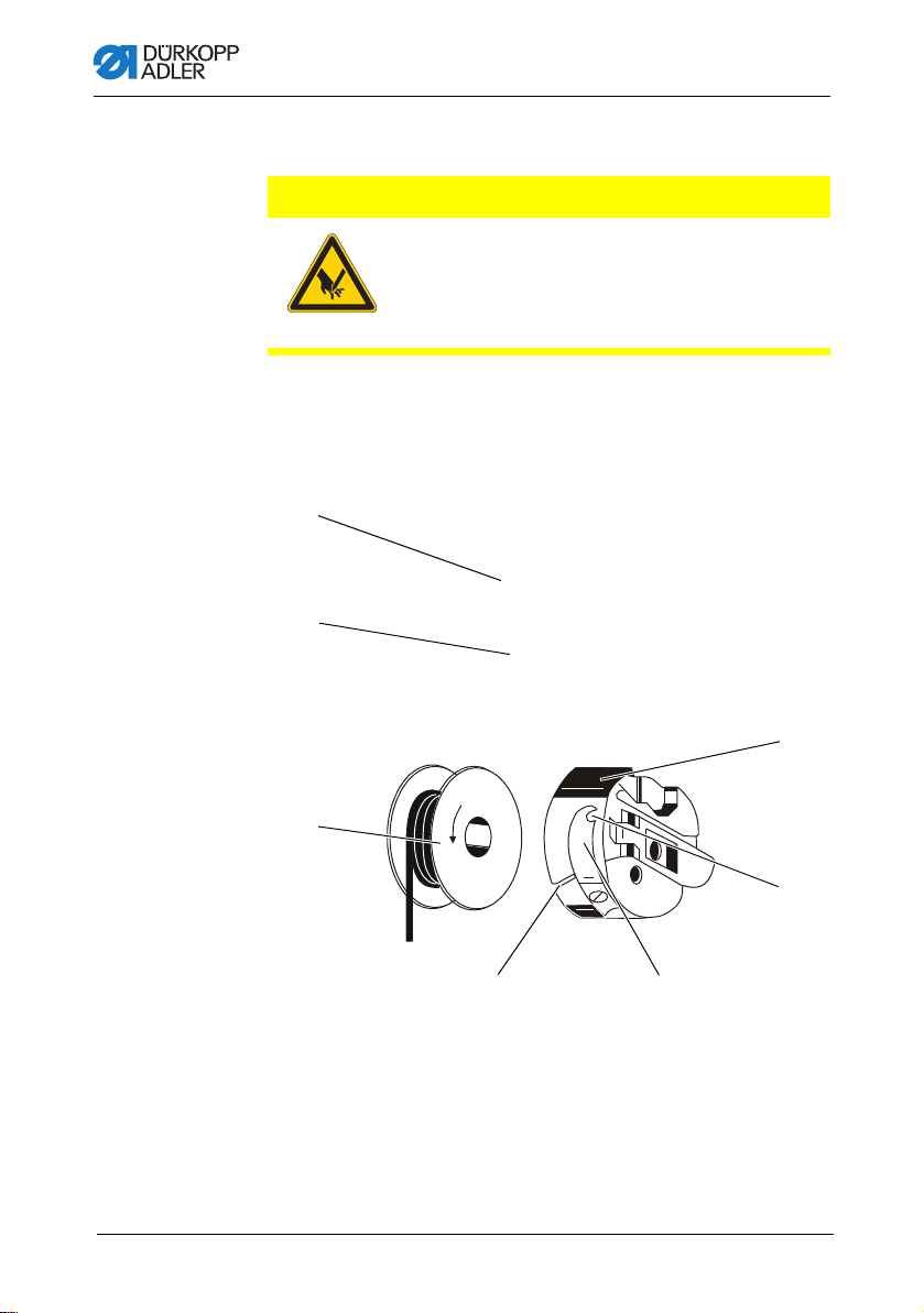
4.5 Winding the hook thread
NOTICE
Property damage may occur!
Moving the bobbin without performing sewing can cause
damage to the presser foot and the bobbin case in the hook.
Activate bobbin mode if you wish to wind the hook thread
without performing sewing.
Fig. 6: Winding the hook thread
(1) - Winder flap
(2) - Bobbin
To wind the hook thread:
1. Fit the bobbin (2) on the bobbin shaft.
2. Thread the hook thread as shown in the following figure.
3. Wind the hook thread clockwise on to the bobbin core.
4. Swing the bobbin winder flap (1) against the bobbin.
5. Switch the main switch on.
6. Start sewing.
7. Once the bobbin is full, the winder switches off automatically
( Service instructions).
8. Pull off the bobbin, clamp the thread under the cutter (3) and
tear it off.
Operating Instructions 650-16 - 02.0 - 08/2016 25
(3) - Cutter
Page 28
4.6 Replacing the hook thread bobbin
④⑤
⑥
⑦
①
③
②
CAUTION
Risk of injury from sharp and moving parts!
Cutting or crushing possible.
Switch off the machine before replacing the hook
thread bobbin.
Fig. 7: Replacing the hook thread bobbin
Operation
(1) - Bobbin housin g flap
(2) - Hook cover
(3) - Bobbin
(4) - Slot
(5) - Tension spring
(6) - Hole
(7) - Bobbin hous in g upper section
26 Operating Instructions 650-16 - 02.0 - 08/2016
Page 29

Operation
To replace the hook thread bobin:
Removing an empty bobbin
1. Push the hook cover (2) downwards.
2. Move the needle to the up position.
3. Lift the bobbin housing flap (1).
4. Remove the bobbin housing upper section (7) with the
bobbin (3).
5. Remove the empty bobbin (3) from the bobbin housing upper
section (7).
Inserting a full bobbin
1. Insert the full bobbin (3) into the bobbin housing upper
section (7).
2. Feed the hook thread through the slot (4) under the tensioning
spring (5) into the hole (6).
3. Pull the hook thread approx. 5 cm out of the bobbin
housing (7).
4. The bobbin must rotate in the direction of the arrow when
pulling out the thread.
5. Insert the bobbin housing (7) again.
6. Push the hook cover (2) upwards.
4.7 Thread tension
Together with the bobbin thread tension, the needle thread tension
influences the seam pattern.
The needle thread tension is defined by the pre-tensioner, the
main tensioner and the additional tensioner.
Proper Setting
The main tension (1) should be set as low as possible.
The thread interlacing should be exactly in the middle of the
material being sewn.
With thin sewn material, excessive thread tension can lead to
undesired gathering and thread breakages.
Operating Instructions 650-16 - 02.0 - 08/2016 27
Page 30

Fig. 8: Thread tension
DA150018_V52_XX
②
①
③
①
(1) - Identical needle thread and bobbin thre ad tension
(2) - Bobbin thread tension higher than needle thread tension
(3) - Needle thread tension higher than bobbin thread tension
4.7.1 Setting the needle thread tension
Fig. 9: Setting the needle thread tension
Operation
(1) - Main tensioner
To set the needle thread tension:
1. Set the main tensioner (1) via the control panel so that a even
stitch pattern is achieved.
When the thread is cut, the main tensioner (1) is opened
automatically.
28 Operating Instructions 650-16 - 02.0 - 08/2016
Page 31

Operation
4.7.2 Setting the hook thread tension
CAUTION
Risk of injury from sharp and moving parts!
Cutting or crushing possible.
Switch off the machine before setting the hook
thread tension.
Fig. 10: Setting the hook thread tension (1)
Proper setting
The hook thread tension must be set so that the resulting stitch
pattern looks like the figure in ( p. 27).
At the recommended hook thread tension of e.g. 25 g (measured
with a full bobbin), 12.5 g should be generated by the braking
spring and 12.5 g by the tensioning spring.
The basic setting for the tensioning spring is performed as follows:
• When the bobbin housing contains a full bobbin it must
sink slowly under its own weight.
The braking spring prevents the bobbin running on when the
thread has been cut.
Operating Instructions 650-16 - 02.0 - 08/2016 29
Page 32

Fig. 11: Setting the hook thread tension (2)
①② ③
Operation
(1) - Braking spring
(2) - Tension spring
(3) - Regulating screw
To set the hokk thread tension:
1. Turn back the adjusting screw (3) so far that the tension on
the tensioning spring (2) is completely removed.
2. Bend the braking spring (1) such that half the recommended
hook thread tension value is applied through the braking
spring.
3. Insert the bobbin into the bobbin housing upper section and
thread in the hook thread ( p. 32).
4. Insert the bobbin housing together with the bobbin into the
hook.
5. Hold the free thread end tightly with one hand.
6. Turn the handwheel until the sewing machine performs one
stitch.
7. Pull the hook thread on to the upper side of the needle hole
using the needle thread.
8. Remove the hook thread in the direction of sewing at an angle
of 45°. About half the tension value should be evident.
9. Then tighten the adjusting screw (3) up to the recommended
tension value.
30 Operating Instructions 650-16 - 02.0 - 08/2016
Page 33

Operation
①
②
③
4.8 Setting the needle thread regulator
The needle thread regulator regulates the amount of needle thread
required for forming the stitch. An optimum sewing result is possible only when the thread regulator is exactly adjusted.
Proper setting
With the correct setting the needle thread loop must slide over the
thickest part of the hook at low tension.
When the largest thread quantity is required then the thread
tension spring (3) must be pulled approx. 0.5 mm down from its
upper end position. This occurs when the needle thread loop
matches the maximum hook diameter.
Fig. 12: Setting the needle thread regulator
(1) - Screw
(2) - Needle thread regulator
To set the needle thread regulator:
1. Loosen the screw (1).
2. Change the setting of the thread regulator (2).
3. Tighten the screw (1).
Operating Instructions 650-16 - 02.0 - 08/2016 31
(3) - Thread tensioning spring
Page 34

4.9 Raising the presser feet
①
②③
CAUTION
Risk of injury from moving parts!
Crushing possible.
Do not reach under the raised presser feet.
Fig. 13: Raising the presser feet
Operation
32 Operating Instructions 650-16 - 02.0 - 08/2016
(1) - Presser feet
(2) - Additional pedal (optional)
The presser feet (1) can be raised by an electric motor, by depressing the pedal (3).
To raise the presser feet:
1. Push the pedal (3) halfway backwards.
The presser feet (1) raise.
OR
(3) - Pedal
Page 35

Operation
1. Push the pedal (3) fully backwards.
2. Activate the thread cut-off an d ra ise th e pr esser feet (1).
Functions of the optional additional pedal
The left pedal (2) has a dual function. Depending on the setting
of the technician level it either alters the fullness or the curve
support ( Service instructions).
• In automatic mode:
The value for fullness or curve support is corrected for the current step.
• In manual mode:
The value for fullness or curve support is selected.
To activate the functions of the optional additional pedal:
1. Push the additional pedal:
• Push the pedal forwards: Increase the value
• Push the pedal backwards: Decrease the value
Operating Instructions 650-16 - 02.0 - 08/2016 33
Page 36

Operation
①
4.10 Knee switch
The knee switch (1) is used to switch the seam programs from
one step to the next, both in automatic mode and also in programming mode.
Fig. 14: Knee switch
(1) - Knee switch
To use the knee switch:
1. Depress the knee switch.
The next step is called up.
4.11 Sewing
Before starting sewing
Initial situation • Pedal is in the rest position.
Sewing machine is at a standstill.
Needle is up. Presser foot is down.
Position material at the start of
the seam
At the start of the seam
34 Operating Instructions 650-16 - 02.0 - 08/2016
• Push the pedal half backwards.
The presser foot rises.
• Position the sewing material.
• Release the pedal.
The presser foot descends on to the sewing material.
Page 37

Operation
Starting bartack and sewing
the seam
In the middle of the seam
Stopping sewing • Release the pedal (position 0).
Continue sewing
(after releasing the pedal)
Intermediate raising • Push the pedal half backwards.
Altering the fullness • Press the fullness button or the left pedal.
At the end of the seam
Remove the material to be sewn • Push the pedal fully backwards and keep it there.
• Push the pedal forwards and keep it there.
Starting bartack is sewn (if specified).
Then the machine sews along the seam at the speed
determined by the pedal.
The machine stops in the 1st position (needle down) or
in the needle up position (depending on the setting
chosen).
The presser foot is down or raised
(depending on the setting chosen).
• Press the pedal forwards.
The machine continues to sew at the specified speed.
The presser feet are raised.
• Correct the material.
• Release the pedal.
The presser feet are lowered.
The selected fullness value is activated.
The end bartack is sewn (if activated).
The thread is cut off (if activated).
The machine stops in the 2nd position.
The needle is up. The presser feet are raised.
• Remove the sewn material.
• Release the pedal.
The presser feet are lowered.
Operating Instructions 650-16 - 02.0 - 08/2016 35
Page 38

Operation
36 Operating Instructions 650-16 - 02.0 - 08/2016
Page 39

Control with the OP3000 control panel
5 Control with the OP3000 control panel
5.1 OP3000 control panel
Fig. 15: OP3000 control panel
All settings in the control for the 650-16 are performed using the
OP3000 control panel.
Key Function
0 to 16 Setting the fullness
ESC Cancel the function
OK Confirm the settings
P Function is different for each menu
S Function is different for each menu
F Function is different for each menu
Operating Instructions 650-16 - 02.0 - 08/2016 37
Inputting the parameter value (if the field for the parameters
is activated)
Selection of a parameter that is shown in the display
• Press the key under the desired symbol.
The function is selected.
Exit the menu
Activate the input
Selection to the right
Selection to the left
Back one menu level
Increase the value
Scroll through the list (upwards)
Page 40

Key Function
Control with the OP3000 control panel
A Upper softkey - 1
B Upper softkey - 2
+/- Switch between increase and decrease the fullness
Decrease the value
Scroll through the list (downwards)
Assignment is different for each menu
Assignment is different for each menu
5.2 Switching on the machine
Fig. 16: Switching on the machine (1), Display of the firmware and Software version
To switch on the machine:
1. Switch on the main switch.
The software version appears on the display:
• On the left of the screen the control panel firmware
• On the right of the screen the control software version
The machine performs a reference run:
The display shows the program last used, or manual mode.
Fig. 17: Switching on the machine (2), Display of the program last used
38 Operating Instructions 650-16 - 02.0 - 08/2016
Page 41

Control with the OP3000 control panel
Fig. 18: Switching on the machine (3), Display in manual mode
5.3 Control operating modes
The 650-16 control has 4 available operating modes:
• Manual mode (program 000)
Manual mode is the simplest operating mode.
There are no sewing programs and no inputs
for individual sewing steps.
Changes to the fullness, stitch length, thread tension, curve
support and also the activation of other functions are always
implemented immediately.
Thus all the major sewing parameters can be changed manually during the sewing process.
• Automatic mode (program 001 - 999)
Automatic mode allows sewing programs to be executed.
The seams are divided into individual sections (steps) within
the sewing programs. Each step is assigned its own individual sewing parameters such as fullness, curve support etc.
• Quick programming
Quick programming allows very quick and simple creation of
new sewing programs.
• Programming mode
Programming mode allows new sewing programs to be created, edited, deleted, copied, and mirrored (left sleeve / right
sleeve).
Operating Instructions 650-16 - 02.0 - 08/2016 39
Page 42

Control with the OP3000 control panel
5.4 Manual mode
Fig. 19: Manual mode
The following table shows the individual symbols (parameters) in
the display and the functions of the keys on the control panel.
When a parameter is selected, its color on the display changes.
When a parameter is changed, its new value is loaded immediately.
Symbol Meaning
(depending on the assignment)
Quick programming
• Press the upper softkey
Quick access function (softkey menu)
• Press the lower softkey, p. 42.
Program number
Value range: 000 to 999
Program 000 indicates that the control is in
Manual mode.
/ to select the Program parameter.
•Use
/ to change the program number.
•Use
Or:
• Input the program number directly using the keys
0 to 9 and confirm with OK as required.
This takes you into Automatic mode.
Fullness
Value range: Upper fullness: 0 to 16
Lower fullness: 0 to -6
• Use the keys 0 to 16 to select the desired value.
• Use the +/- key to select upper or lower fullness.
Or:
• Use the second pedal to select the fullness, if fitted.
40 Operating Instructions 650-16 - 02.0 - 08/2016
Page 43

Control with the OP3000 control panel
Symbol Meaning
Stitch length
Value range: 1.0 to 5.5 mm
•Use
•Use
Thread tension
Value range: 1 to 99
•Use
•Use
Curve support
Value range: 0 to 6
•Use
•Use
Other parameters
p. 43
Seam length in mm
After the thread has been cut off, the display is
retained. Measurement restarts when sewing starts
again.
/ to select the Stitch length parameter.
/ to change the stitch length
/ to select the Thread tension parame-
ter.
/ to change the thread tension
/ to select the Curve support parameter.
/ to change the curve support
P Creating a program
p. 58
+/- Switch between upper and lower fullness
ESC, F and S No function assigned
0 – 16 Fullness values
OK No function assigned
Operating Instructions 650-16 - 02.0 - 08/2016 41
Page 44

Control with the OP3000 control panel
5.4.1 Quick access function (softkey menu)
Here you have quick access to functions during the sewing process and can also assign a function to the upper softkey.
To use the quick access function:
1. Press the lower softkey .
The following information is shown on the display:
Fig. 20: Quick access function (softkey-Menu)
2. Call up a function:
• Press the numeric key under the designed function.
OR
Assigning a function to the upper softkey:
• Press the numeric key under the designed function and
at the same time press the upper softkey.
The function is assigned to the upper softkey and can be
called up by pressing the key.
3. Press ESC to exit the menu.
Symbol Meaning
Manual bartack
• Press the key 1 and keep it pressed for a manual bartack.
Bartack suppression on/off
• Press the key 2.
The bartacks are switched on or off.
Needle position up / down
• Press the key 3.
If sewing is stopped within the seam, the needle is
positioned up or down.
42 Operating Instructions 650-16 - 02.0 - 08/2016
Page 45

Control with the OP3000 control panel
Symbol Meaning
Automatic step progression on/off
(available only in Automatic mode)
• Press the key 4.
Automatic step progression is enabled/disabled whilst
sewing a seam.
Quick programming
• Press the key 5.
Quick programming starts.
Bobbin mode
• Press the key 6.
• Push the pedal halfway backwards.
Bobbin mode is ended.
5.4.2 Menu for other settings
To use the menu for other settings:
1. Use / to select the Other parameters.
2. Press the OK key.
3. Use / to select the desired parameter.
4. Select the parameter using the OK key.
5. Change values using the / keys.
6. Click on the OK button to confirm.
7. Press or ESC to exit the menu.
Symbol Meaning
Alternate (foot alternation)
Value range: 0.0 to 2.5 mm
Foot Press. (presser foot pressure)
Value range: 1 – 15
Operating Instructions 650-16 - 02.0 - 08/2016 43
Page 46

Control with the OP3000 control panel
Symbol Meaning
Start Tack (bartack at the start of a seam)
Value range: on/off
End Tack (bartack at the end of a seam)
Value range: on/off
Thread Trim (thread cutoff)
Value range: on/off
5.4.3 Sewing process
Sewing without fullness
To sew without fullness:
1. Input values for stitch length, thread tension, curve support
and foot alternation.
2. Push the pedal forwards and sew.
Sewing with fullness
To sew with fullness:
1. Change the fullness with the left pedal (optional)
(if set at the technician level).
OR
2. Alter the fullness using the 0 to 16 and +/- keys.
Altering parameters whilst within the seam
To alter parameters whilst within the seam:
1. Move the pedal to the 0 position.
2. Change the desired parameter on the control panel.
3. Push the pedal forwards again and sew.
The seam will be sewn using the altered parameter value.
44 Operating Instructions 650-16 - 02.0 - 08/2016
Page 47

Control with the OP3000 control panel
5.5 Automatic mode
Program numbers 001 to 999.
To use the automatic mode:
1. Use
2. Use
/ to select the Program parameter.
/ to select the program number 1 or another one if
available.
The control switches to automatic mode and the following
information appears in the display:
Fig. 21: Automatic mode
The following table shows the individual symbols in the display
and the functions of the keys on the control panel.
Operating Instructions 650-16 - 02.0 - 08/2016 45
Page 48

Control with the OP3000 control panel
5.5.1 Before starting sewing
Symbol Meaning
Quick programming (depending on the assignment)
• Press the upper softkey
Quick access function (softkey menu)
• Press the lower softkey
Program number
Value range: 000 to 999
/ to select the Program parameter.
•Use
/ to change the program number.
•Use
Or:
• Input the program number using the 0 - 9 keys
and confirm with OK
If you select program 000, the control selects Manual
mode
Right sleeve / left sleeve
The machine can sew only right sleeves, only left sleeves, or right and left sleeves alternately
•Use
/ to select a right sleeve or a left sleeve
(if programs exist for both).
as required.
Steps
Number of steps contained in the current program.
Stitch length
Value range: 1.0 to 5.5 mm
The stitch length can be altered before starting sewing.
The altered value applies throughout the entire sewing
program.
/ to select the Stitch length parameter.
•Use
•Use
/ to adjust the stitch length.
Thread tension
Value range: 1 to 99
The thread tension can be altered before starting
sewing.
The altered value applies throughout the entire sewing
program.
/ to select the Thread tension parameter.
Use
•Use
/ to change the thread tension
46 Operating Instructions 650-16 - 02.0 - 08/2016
Page 49

Control with the OP3000 control panel
①②
Symbol Meaning
Other parameters
Foot Press. (presser foot pressure)
Fulln.Corr. (fullness correction)
•Use
• Press the OK key.
•Use
• Select the parameter using the OK key.
• Change values using
• Click on the OK button to confirm.
•Press
Program bar
Length per step in mm,
or a dash (-) if no automatic step
progression
P Programming mode
Switches into programming mode.
ESC, F, S No function assigned
/ to select the Other parameters para-
meter.
/ to select the fullness correction or the
presser foot pressure.
/.
or ESC to exit the menu.
1. Sew, press the knee switch or press the OK key.
The program switches to the 1st step.
5.5.2 Sewing
1. Push the pedal forwards and sew.
The following information is shown on the display:
Fig. 22: Sewing (1)
(1) - Program bar (2) - Current step
Operating Instructions 650-16 - 02.0 - 08/2016 47
Page 50

Control with the OP3000 control panel
The parameter values for the current step are shown in the display.
The program bar (1) shows the progress of the seam.
The number under the current step shows the outstanding length
of the step.
The program bar shows half the current step in bold.
Fig. 23: Sewing (2), Current step
Completed steps are shown fully in bold.
Fig. 24: Sewing (3), Completed step
The following table lists the functions that can be performed in the
course of the seam.
Key/Pedal Function
+/-
and
0 - 16
2nd pedal
(optional)
Knee switch Next program step
/
3
/
ESC, P, F, S, OKNo function assigned
48 Operating Instructions 650-16 - 02.0 - 08/2016
Temporary correction of the fullness value
(valid only for the current step)
Temporary correction of the fullness value or the
curve support (depending on the setting in the techni-
cian level)
(valid only for the current step)
Stop forward/back or to the start of the step
Switch the sleeve side (if programmed) in the
1st step at the start of the step
Correction of the thread tension
The value is saved.
Page 51

Control with the OP3000 control panel
Key/Pedal Function
Pedal halfway
back
Pedal fully
back
Lower softkey Softkey menu
Raise the presser foot
Cut off the thread
The program remains stopped at the cutoff point.
p. 40
5.5.3 Canceling the program
To cancel a program:
1. Cut off (push the pedal ful ly ba ck).
2. Press the ESC key.
Or:
Push the pedal fully back
The program is interrupted.
5.6 Quick programming
If is assig ne d to the upper softkey:
1. Press the upper softkey .
The following display appears:
Fig. 25: Quick programming (1)
2. Continue with handling step 3.
Operating Instructions 650-16 - 02.0 - 08/2016 49
Page 52

Control with the OP3000 control panel
If is not assigned to the upper softkey:
1. Press the key.
The softkey menu appears.
Fig. 26: Quick programming (2)
2. Press the key 5.
3. Use
/ or the keypad keys 0 – 9 to select a program num-
ber.
4. Press the OK key.
The following information is shown on the display,
the P in the program number field flashes:
Fig. 27: Quick programming (3)
50 Operating Instructions 650-16 - 02.0 - 08/2016
Page 53

Control with the OP3000 control panel
The following table shows the individual symbols in the display
and the functions of the keys on the control panel.
Symbol Meaning
Automatic step progression on/off
• Press the upper softkey
Activates / deactivates automatic step progression for
the current step.
Current program to be created
Current sleeve side to be created
(pre-set at the technician level)
Current step
•Use
•Use
• Press the OK key to edit other parameters for the
Fullness
Value range: -6 to 16
• Use the keys 0 to 16 to select the desired value.
Or:
• Use the second pedal to select the fullness, if fitted.
• Use the +/- key to select upper (+) or lower (-) full-
/ to select the Step parameter.
/to switch to the next/previous step.
step, p. 54.
ness.
Stitch length for the current step
Value range: 1.0 to 5.5 mm
/ to select the Stitch length parameter.
•Use
/ to change the stitch length.
•Use
Operating Instructions 650-16 - 02.0 - 08/2016 51
Page 54

Control with the OP3000 control panel
Symbol Meaning
Thread tension
Value range: 0 to 99
/ to select the Thread tension parame-
•Use
ter.
•Use
/ to change the thread tension.
Curve support
Value range: 0 to 6
•Use
/ to select the Curve support parameter.
/ to change the curve support.
•Use
Length of the current step in mm
5.6.1 Creating a program by keyboard input
To create a program by keyboard input:
1. Set all the parameters for each step.
2. Step through to the next step using the knee switch.
Cancel with ESC
Before the S key is pressed, program creation can be canceled
at any time by pressing the ESC key.
Once all steps are complete:
3. Press the S key.
The program is saved.
52 Operating Instructions 650-16 - 02.0 - 08/2016
Page 55

Control with the OP3000 control panel
Depending on the settings at the technician level
• The sleeve side that was created is mirrored
• The sleeve side that was created is not mirrored
• The teach-in for the 2nd sleeve side is opened
• The selection screen for the action of creating the
2nd sleeve side is opened
The machine switches to Automatic mode.
The program that was just created is selected.
Fig. 28: Creating a program by keyboard input
5.6.2 Creating a program by sewing the seam (Teac hIn)
To create a program by sewing the seam:
1. Insert the material to be sewn.
2. Input the parameters for the 1st step (fullness, stitch length,
thread tension and curve support).
3. Sew the first step.
4. Operate the knee switch.
The program switches to the next step.
Cancel with ESC
Before the S key is pressed, program creation can be canceled
at any time by pressing the ESC key.
If a section of seam has already been sewn the program will have
been saved and must if necessary be deleted ( p. 61).
Operating Instructions 650-16 - 02.0 - 08/2016 53
Page 56

Control with the OP3000 control panel
Once all steps are complete:
5. Press the S key.
The program is saved.
The following display appears:
Fig. 29: Creating a program by sewing the seam (Teach-In) (1)
6. Sew the overlap.
7. Push the pedal fully back.
The sleeve that was created is mirrored, depending on the
settings at the technician level.
The machine switches to Automatic mode.
The program that was just created is selected.
Fig. 30: Creating a program by sewing the seam (Teach-In) (2), Displaying the newly created program
5.7 Edit mode
Edit mode allows existing programs to be edited or deleted.
Programming mode should be used to create new programs,
5.8 Programming mode, page 56.
To use the edit mode:
1. In Automatic mode, press the P key.
The control switches to Edit mode.
The program previously selected can now be edited.
The following information is shown on the display,
the P in the program number field flashes:
54 Operating Instructions 650-16 - 02.0 - 08/2016
Page 57

Control with the OP3000 control panel
Fig. 31: Edit mode
2. Use / to select the program to be edited, the sleeve side
and the step; and use
Information
The step to be edited can also be selected using the knee switch.
The selected step is shown bold in the program bar.
3. Use
/ to select the parameter to the changed for the res-
pective step, and use
5.7.1 Changing further parameters for the current step
/ to deselect them.
/ to change it.
To change further parameters for the current step:
1. Use
/to select the field .
2. Press the OK key.
The submenu opens.
3. Use
/ to select the desired parameter.
4. Press the OK key to activate or deactivate the parameter, or
/ to change its value and press OK to confirm it.
use
Operating Instructions 650-16 - 02.0 - 08/2016 55
Page 58

Control with the OP3000 control panel
Symbol Meaning
Step. Len. (step length)
Auto Forward
(automatic step progression)
Alternate (sewing foot alternation)
Foot Press (presser foot pressure)
5. Exit the submenu using ESC or
5.7.2 Changing further parameters for the selected program
This menu allows further parameters for the current sewing
program to be changed.
Tochange further parameters for the selected program:
1. Use
/to select the field .
2. Press the OK key.
The submenu opens.
3. Use
/ to select the desired parameter.
4. Press the OK key to activate or deactivate the parameter, or
/ to change its value and press OK to confirm it.
use
56 Operating Instructions 650-16 - 02.0 - 08/2016
Page 59

Control with the OP3000 control panel
Symbol Meaning
Thr. Tens (thread tension)
Stitchlen. (stitch length)
Foot Press. (presser foot pressure)
Fulln. Corr. (fullness correction)
Start Tack (bartack at the start of a seam)
End Tack (bartack at the end of a seam)
Thread Trim (thread cutoff)
5. Exit the submenu using ESC or .
Operating Instructions 650-16 - 02.0 - 08/2016 57
Page 60

Control with the OP3000 control panel
5.8 Programming mode
5.8.1 Creating a program
To create a program:
1. In Edit mode, press the key.
The softkey menu appears.
Fig. 32: Creating a program (1)
2. Press the key.
The following display appears:
Fig. 33: Creating a program (2)
The control displays the next free program number.
3. Press OK to load the program number.
OR
Select another program number using
/ or input a pro-
gram number using the keypad keys 0 - 9 and then press
OK.
The program number is loaded.
The following display appears, with P flashing:
58 Operating Instructions 650-16 - 02.0 - 08/2016
Page 61

Control with the OP3000 control panel
Fig. 34: Creating a program (3)
4. If necessary change the sleeve side or other parameters,
5.7 Edit mode, page 52.
5. Press the key.
The following display appears, with P flashing:
Fig. 35: Creating a program (4)
The rest of the procedure is as described in the section Quick
programming ( p. 49).
6. Select whether progression to the individual steps to be pro-
grammed should be by using the knee switch or by automatic
progression.
7. Press the key.
Once the creation of the program is complete and the “S” key has
been pressed or after the thread cutoff has been entered, the
following query window appears:
Fig. 36: Creating a program (5)
8. Select whether
• the sleeve side that was programmed should be mirrored
• the sleeve side that was programmed should not be mirrored
• the teach-in for the 2nd sleeve side should be opened.
Operating Instructions 650-16 - 02.0 - 08/2016 59
Page 62

Control with the OP3000 control panel
5.8.2 Copying the program
The selected program is copied into a new program number.
To copy the program:
1. Press the key.
The softkey menu appears.
Fig. 37: Copying the program (1)
2. Press the key.
The following display appears:
Fig. 38: Copying the program (2)
The control displays the next free program number.
3. Press OK to load the program number.
OR
Select another program number using
/ or input a pro-
gram number using the keypad keys 0 - 9 and then press
OK.
The program number is loaded.
The following display appears, with the program number
flashing:
60 Operating Instructions 650-16 - 02.0 - 08/2016
Page 63

Control with the OP3000 control panel
Fig. 39: Copying the program (3)
4. Load the desired changes into the new program.
5. Press the ESC key.
The control exits Programming mode and reverts to Auto-
matic mode.
5.8.3 Deleting a program
The selected program is deleted.
To delete a program:
1. Press the key.
The softkey menu appears.
Fig. 40: Deleting a program
2. Press the key.
3. Press the ESC key.
The control exits Programming mode and reverts to Auto-
matic mode.
Operating Instructions 650-16 - 02.0 - 08/2016 61
Page 64

Control with the OP3000 control panel
5.8.4 Mirroring the program
The sleeve side already programmed is mirrored over to the other
sleeve side.
To mirror a program:
1. Press the key.
The softkey menu appears.
Fig. 41: Mirroring a program
2. Press the key.
3. Press the ESC key.
The control exits Programming mode and reverts to Auto-
matic mode.
62 Operating Instructions 650-16 - 02.0 - 08/2016
Page 65

Control with the OP7000 control panel
6 Control with the OP7000 control panel
6.1 OP7000 control panel
All settings for the 650 sewing machine are performed using the
OP7000 control panel.
Fig. 42: OP7000 control panel
The activation of the sewing motor and the stepper motors is
performed by the DAC3 control in conjunction with the OP7000
control panel with the user interface in symbolic representation.
The program automation permits either manual or automatic control of fullness, optionally upper or lower, curve support and also
the programming of sewing steps with individual parameters.
Up to 999 sewing programs can be saved.
Each sewing program can contain up to 30 sewing steps.
Each sewing step can be assigned various parameters such as
stitch length, fullness values, curve support, thread tension,
segment length etc.
The seam programs are displayed continuously whilst sewing is
in progress. Programs can be mirrored for the other side of the
sewing material.
Operating Instructions 650-16 - 02.0 - 08/2016 63
Page 66

Control with the OP7000 control panel
6.2 Switching on the machine
To switch on the machine:
1. Switch on the main switch.
The OP7000 control panel is switched on.
• The machine class is shown on the left of the display, the
firmware is shown on the right.
• The machine performs a reference run.
• The control panel starts in the mode that was active when
it was switched off - MAN or AUTO.
6.3 Control operating modes
The control has four operating modes avai l ab l e:
• Manual mode MAN
Manual mode is the simplest operating mode.
There are no sewing programs and no inputs for individual
sewing steps.
Changes to the fullness, stitch length, thread tension, curve
support and also the activation of other functions are implemented immediately.
Thus all the major sewing parameters can be changed manually during the sewing process.
• Automatic mode AUTO
Automatic mode allows sewing programs to be executed.
The seams are divided into individual sections within the se-
wing programs. Each step is assigned its own individual sewing parameters such as fullness etc.
• Programming mode
In Programming mode, new seam programs can be created
(PROGRAMMING), existing seam programs can be edited,
deleted, copied and mirrored (EDIT) and also optimized
(Length Correction).
• Service mode SERVICE
Service mode contains functions for use during service work.
Service mode is password-protected, to avoid accidentally
changing the machine settings.
64 Operating Instructions 650-16 - 02.0 - 08/2016
Page 67

Control with the OP7000 control panel
6.4 General operation
Operation is performed using the control panel. All functions and
inputs are triggered by touching the screen.
Numeric values for the individual parameters and text for the
program names can be input in the individual operating modes.
The inputs are performed using separate user interfaces.
6.4.1 Inputting numeric values
Fig. 43: Inputting numeric values
The user interface for inputting numeric values consists of the
following elements:
Header, consisting of:
• Symbol of the selected parameter
• Name of the parameter
• Value range of the parameter
• Symbol for exiting the user interface
Operating Instructions 650-16 - 02.0 - 08/2016 65
Page 68

Control with the OP7000 control panel
Input line for the value
Keypad
Meaning of the buttons
Symbols/buttons Meaning
Value input
Change of plus/minus sign
Input of a decimal point for values that permit places of decimals
Changing the value incrementally up or
down
Delete the input value
Exit the user interface without inputting or
saving any values
Save the value that was input and exist the
user interface
66 Operating Instructions 650-16 - 02.0 - 08/2016
Page 69

Control with the OP7000 control panel
6.4.2 Entering text
Fig. 44: Entering text
The user interface for inputting text consists of the following elements:
Header, consisting of:
• Symbol for a new seam program
• Symbol for exiting the user interface
Operating Instructions 650-16 - 02.0 - 08/2016 67
Page 70

Control with the OP7000 control panel
Input line for the text
Keypad
Meaning of the buttons
Symbols/buttons Meaning
Input of numbers in the text
Input of text
Input of a hyphen
Input of a underscore
Exit the user interface without inputting or
saving any text
Input of a space
Switching between upper case/lower case
Delete letters/digits from the input line
Save the value that was input and exist the
user interface
68 Operating Instructions 650-16 - 02.0 - 08/2016
Page 71

Control with the OP7000 control panel
③
④
①
②
6.5 Manual mode MAN
Fig. 45: Manual Mode MAN
(1) - Header
(2) - Left pane
Header (1)
Operating mode MAN is displayed.
Left pane (2)
Buttons for manually inputting the fullness and the curve support
are displayed here.
Middle pane (3)
The symbols for all the parameters that can be set are displayed
here. The gray fields above the parameter symbols show the
respective current values.
Right pane (4)
Another user interface or another operating mode can be selected
here.
(3) - Middle pane
(4) - Right pane
Operating Instructions 650-16 - 02.0 - 08/2016 69
Page 72

Control with the OP7000 control panel
6.5.1 Parameters that can be set in MAN mode
The following table lists the parameters that can be set in MAN
programming mode.
Symbols Meaning
Setting the fullness, p. 71
Setting the curve support.
Other program parameters in manual mode MAN,
p. 72
Inputting the needle thread tension
Inputting the stitch length in mm
To set parameters in mode MAN:
1. Press the desired button.
The user interface for setting the parameter is displayed.
For some parameters the setting is more than just a numerical
value. These parameters are described below.
70 Operating Instructions 650-16 - 02.0 - 08/2016
Page 73

Control with the OP7000 control panel
MAN mode Setting the fullness
The following table lists the symbols and buttons for manually
setting the fullness.
Symbols/buttons Meaning
To set the fullness:
Inputting the fullness
The fullness setting is displayed by
a button highlighted in red.
Select the type of fullness:
• Upper (upper transport)
• Lower (lower transport)
The fullness selected is displayed in an
activated control field.
Display of further buttons for inputting the
fullness. The buttons 0 to 16 are available
for input.
1. Select the type of fullness.
The type of fullness selected is displayed in an activated
control field within the symbol.
2. If a higher or lower degree of fullness is required, use the
arrow keys to display more buttons.
3. Input the fullness using the buttons 0 to 16.
Operating Instructions 650-16 - 02.0 - 08/2016 71
Page 74

Control with the OP7000 control panel
Setting the curve support
The following table lists the symbols and buttons for manually
setting the curve support.
The default setting is a value of 2.
Symbols/buttons Meaning
Inputting the curve support
The curve support is displayed by a button
highlighted in red.
To set the curve support:
1. Input the curve support using the buttons 1 to 6.
MAN mode Other program parameters
After the Other program parameters button has been pressed,
an overview of all the available parameters is displayed.
Fig. 46: Other program parameters
72 Operating Instructions 650-16 - 02.0 - 08/2016
Page 75

Control with the OP7000 control panel
Parameters Meaning
Needle Stop Position Up When sewing stops the needle position is
Foot Stroke Alternation Presser foot alternation whilst the needle is
Foot Pressure Presser foot pressure
Backtack at Start Backtack at start of the seam on (activa-
Backtack at End Backtack at end of the seam on (activated)
Thread Trim Thread cutoff at end of the seam on (acti-
up (activated) or down (not activated)
in the seam
Value range: 0 ... 2.5 mm
Value range: 1 ... 10
ted) or off (not activated)
or off (not activated)
vated) or off (not activated)
6.5.2 Sewing process
1. Set the fullness ( p. 71).
2. Set the curve support.
3. Input the values for needle thread tension and stitch length.
4. Push the pedal forwards and sew.
The length in mm sewn in the seam is displayed.
When the thread is cut off, the display is reset.
Changing parameters during the seam
1. Move the pedal to the 0 position.
2. Change the desired parameter on the control panel ( p. 70).
3. Push the pedal forwards and sew.
The seam will be sewn using the altered parameter value.
Operating Instructions 650-16 - 02.0 - 08/2016 73
Page 76

Control with the OP7000 control panel
③
④
①
②
6.6 Automatic mode AUTO
Fig. 47: Automatic mode AUTO
(1) - Header
(2) - Left pane
Header (1)
The AUTO operating mode is displayed. The buttons + F%
and - F% offer quick access for setting the fullness values in %.
Left pane (2)
The graphical representation of the entire seam, divided into the
number of programmed sewing steps, is displayed here. A red bar
with an arrowhead indicates the direction of sewing and progress
of the sewn seam.
Middle pane (3)
The number and the name of the selected seam program are
displayed here, together with the symbols for all the parameters
that can be set. The gray fields above the parameter symbols
show the respective current values.
(3) - Middle pane
(4) - Right pane
74 Operating Instructions 650-16 - 02.0 - 08/2016
Page 77

Control with the OP7000 control panel
Right pane (4)
Another user interface or another operating mode can be selected
here.
6.6.1 AUTO parameters that can be set
The following table lists the parameters that can be edited in AUTO
programming mode.
Symbols Meaning
Program selection, p. 76
Select the right or left piece to be sewn
Set the sewing material size, p. 77
Other program parameters in AUTO automatic mode, p. 80
Temporarily setting the fullness value until
the next sewing step, p. 78
Applying a % correction to the fullness
values of all sewing steps, p. 79
Setting the needle thread tension.
If the value is changed in AUTO Automatic
mode it is permanently saved in the
program.
Setting the stitch length in mm.
If the value is changed in AUTO Automatic
mode it is permanently saved in the
program.
Operating Instructions 650-16 - 02.0 - 08/2016 75
Page 78

To set parameters in the Automatic mode AUTO:
1. Press the desired button.
The user interface for setting the desired parameter is dis-
played.
For some parameters the setting is more than just a numerical
value. These extended parameters are described in detail below.
AUTO mode Program selection
Fig. 48: Program selection
Control with the OP7000 control panel
To select a Program:
1. Press on the desired seam program.
The seam program selected is displayed in an activated
control field within the line.
2. Press the OK button.
The seam program selected is loaded in Automatic mode
AUTO.
3. Press the Abort button to cancel the selection of the program.
If necessary the seam program selected is discarded and
the user interface for the Automatic mode AUTO is displayed.
76 Operating Instructions 650-16 - 02.0 - 08/2016
Page 79

Control with the OP7000 control panel
AUTO mode Setting the sewing material size
Fig. 49: Setting the sewing material size
The following information is displayed:
• The currently selected size is indicated by a double
arrow (>>).
• The sizes highlighted in red represent the reference sizes
for the graduation logic.
To set the sewing material size:
1. Press on the desired sewing material size.
The user interface for the Automatic mode AUTO is dis-
played.
Operating Instructions 650-16 - 02.0 - 08/2016 77
Page 80

Control with the OP7000 control panel
AUTO mode Temporarily correcting the fullness value until the next
sewing step
Fig. 50: Temporarily correcting the fullness value until the next sewing
step
Buttons for manually inputting the fullness are displayed in the left
pane.
Symbols/buttons Meaning
Input the fullness
The fullness setting is displayed by a button highlighted in red.
Select the type of fullness:
• Upper (upper transport)
• Lower (lower transport)
The fullness selected is displayed in an
activated control field.
Display of further buttons for inputting the
fullness. The buttons 0 to 16 are available
for input.
78 Operating Instructions 650-16 - 02.0 - 08/2016
Page 81

Control with the OP7000 control panel
To correct the fullness temporarily until the next sewing step:
1. Select the type of fullness.
The type of fullness selected is displayed in an activated
control field within the symbol.
2. If a higher or lower degree of fullness is required, use the
arrow keys to display more buttons.
3. Input the fullness using the buttons 0 to 16.
Information
The fullness value remains active until the next sewing step.
AUTO mode Correcting the fullness ratio
The fullness ratio can be set either by the buttons + F% and - F%
or the fullness correction parameter.
Fig. 51: Correcrting the fullness ratio
To correct the fullness ratio:
1. Input the correction value for the fullness in percent.
Operating Instructions 650-16 - 02.0 - 08/2016 79
Page 82

Control with the OP7000 control panel
Information for inputting numeric values: p. 65.
2. Press the OK button.
The correction value is saved and the previous user inter-
face is displayed.
Information
If the correction value is changed in AUTO Automatic mode it
remains active until the control changes to the next program.
AUTO mode Other program parameters
After the Other program parameters button has been pressed,
an overview of all the available parameters is displayed.
Fig. 52: Other program parameters
Parameters Meaning
Foot Pressure Presser foot pressure
Value range: 1 ... 10
80 Operating Instructions 650-16 - 02.0 - 08/2016
Page 83

Control with the OP7000 control panel
6.6.2 Sewing process
To start the sewing process:
1. Select the seam program, p. 76.
The program number and name of the seam program are
displayed on the user interface. If no name has been saved
for the seam program, <No Name> is displayed.
2. Select the right or left piece to be sewn.
3. Select the size of the piece to be sewn, p. 77.
4. Push the pedal forwards and sew the seam.
The sewing progress is displayed graphically in the left pane
as a red bar.
Fig. 53: Sewing process
The remaining sewing length per sewing step is displayed.
Operating Instructions 650-16 - 02.0 - 08/2016 81
Page 84

Control with the OP7000 control panel
Changing parameters during the seam
To change parameters during the seam:
1. Move the pedal to the 0 position.
2. Change the desired parameter on the control panel.
3. Push the pedal forwards and sew.
The seam will be sewn using the altered parameter value.
Correcting the fullness before or during the seam
To correct the fullness before or during the seam:
1. Move the pedal to the 0 position.
2. Change the fullness correction using the buttons + F% or - F%.
3. Push the pedal forwards and sew.
The changed fullness value is applied and displayed.
Cancel the seam program
To cancel the seam program:
1. Push the pedal fully back.
The seam program is canceled.
82 Operating Instructions 650-16 - 02.0 - 08/2016
Page 85

Control with the OP7000 control panel
③
④
①
②
6.7 Programming mode
Fig. 54: Programming mode
(1) - Header
(2) - Left pane
Header (1)
The EDIT operating mode is displayed.
Left pane (2)
The graphical representation of the entire seam, divided into the
number of programmed sewing steps, is displayed here.
Middle pane (3)
Existing seam programs can be edited here ( p. 84). The num-
ber and the name of the selected seam program are displayed,
together with the symbols for all the parameters that can be set.
The gray fields above the parameter symbols show the respective
current values.
Right pane (4)
Here new seam programs can be created ( p. 90), existing
seam programs can be deleted ( p. 99), copied ( p. 99) and
optimized ( p. 100) (Length Correction).
(3) - Middle pane
(4) - Right pane
Operating Instructions 650-16 - 02.0 - 08/2016 83
Page 86

Control with the OP7000 control panel
6.7.1 Editing existing programs (EDIT)
The following table lists the parameters that can be edited in EDIT
programming mode.
Symbols Meaning
Changing the program name
There is only one display in the EDIT
mode. A new program is automatically
assigned the next free program slot.
Select the right or left piece to be sewn
Set the sewing material size, p. 86
Other program parameters in EDIT programming mode, p. 88
Set the fullness in the current sewing step,
p. 96
Set the curve support in the current sewing
step
Set the needle thread tension in the current
sewing step
84 Operating Instructions 650-16 - 02.0 - 08/2016
Page 87

Control with the OP7000 control panel
Symbols Meaning
To edit an existing program:
1. Press the desired button.
The user interface for setting the desired parameter is dis-
played.
For some parameters the setting is more than just a numerical
value. These extended parameters are described in detail below.
Set the stitch length in mm in the current
sewing step
Switch the seam length measurement in
the current sewing step on or off
Other sewing step parameters in EDIT programming mode, p. 89
Operating Instructions 650-16 - 02.0 - 08/2016 85
Page 88

Control with the OP7000 control panel
EDIT mode Setting the sewing material size
Fig. 55: Setting the sewing material size
The following information is displayed:
• The currently selected size is indicated by a double
arrow (>>).
• The sizes highlighted in red represent the reference sizes
for the graduation logic.
To set the sewing material size:
1. Press on the desired sewing material size.
The EDIT user interface of the programming mode is dis-
played.
86 Operating Instructions 650-16 - 02.0 - 08/2016
Page 89

Control with the OP7000 control panel
EDIT mode Correcting the fullness in the current sewing step
Fig. 56: Correcting the fullness in the current sewing step
Buttons for manually inputting the fullness are displayed in the left
pane.
Symbols/buttons Meaning
Input the fullness.
The fullness setting is displayed by a button highlighted in red.
Select the type of fullness:
• Upper (upper transport)
• Lower (lower transport)
The fullness selected is displayed in an
activated control field.
Display of further buttons for inputting the
fullness. The buttons 0 to 16 are available
for input.
Operating Instructions 650-16 - 02.0 - 08/2016 87
Page 90

Control with the OP7000 control panel
To correct the fullness in the current sewing step:
1. Select the type of fullness.
The type of fullness selected is displayed in an activated
control field within the symbol.
2. If a higher or lower degree of fullness is required, use the
arrow keys to display more buttons.
3. Input the fullness using the buttons 0 to 16.
EDIT mode Other program parameters
After the Other program parameters button has been pressed,
an overview of all the available parameters is displayed.
Fig. 57: Other program parameters
88 Operating Instructions 650-16 - 02.0 - 08/2016
Page 91

Control with the OP7000 control panel
Parameters Meaning
Backtack at Start Backtack at start of the seam on/off
Value range: 0, 1
Backtack at End Backtack at end of the seam on/off
Thread Trim Thread cutoff on/off
Value range: 0, 1
Value range: 0, 1
EDIT mode Other sewing step parameters
After the Other sewing step parameters button has been
pressed, an overview of all the available parameters is displayed.
Fig. 58: Other sewing step parameters
Operating Instructions 650-16 - 02.0 - 08/2016 89
Page 92

Control with the OP7000 control panel
Parameters Meaning
Foot Stroke Alternation Presser foot alternation whilst the needle is
in the seam.
Value range: 0 ... 2.5 mm
Foot Pressure Presser foot pressure.
Value range: 1 ... 10
Maximum Speed Sewing speed/rotational speed.
Value range: 100 ... 4000
6.7.2 Creating a new program (PROGRAMMING)
Prerequisite:
• Operating mode EDIT is displayed.
1. Press the P
NEW
button.
The PROGRAMMING user interface is displayed. Pressing
the P button displays the number of the next free program
slot.
Fig. 59: Creating a new program (PROGRAMMING) (1)
90 Operating Instructions 650-16 - 02.0 - 08/2016
Page 93

Control with the OP7000 control panel
2. Press <No Name> and input a name.
Information for inputting text: p. 67.
Information
If no name is input for the seam program, <No Name> continues
to be displayed.
The first sewing step is displayed with its number in the left
pane.
3. Input all the parameters for the first sewing step.
4. Sew the first sewing step, or manually input the length of the
sewing step using the seam length measurement parameter.
5. Select the next sewing step, either by pressing on the number
of the first sewing steps or by using the knee switch.
The second sewing step is displayed with its number in the
left pane.
Fig. 60: Creating a new program (PROGRAMMING) (2)
6. Repeat step 2 until all the sewing steps have been programmed.
Operating Instructions 650-16 - 02.0 - 08/2016 91
Page 94

Control with the OP7000 control panel
7. Press the END button or cut off the threads.
There are three variants for the program response - depen-
ding on the user's input method:
Variant Program display
The last programmed sewing step was sewn
but not cut off, then ended with END.
The last programmed sewing step was sewn
and threads cut off.
All sewing steps were input manually and
ended with END.
continue with step 8
continue with step 9
continue with step 9
8. If the threads were not cut off after sewing, a message appears. Cut off the threads.
The message is cleared.
Fig. 61: Creating a new program (PROGRAMMING) (3)
9. Select whether the new seam program should be mirrored for
the other side of the sewing material (mirror programmed side
to other side), the other side of the sewing material should be
programmed (program other side) or the programming should
be ended (finish).
92 Operating Instructions 650-16 - 02.0 - 08/2016
Page 95

Control with the OP7000 control panel
10. Select the desired function.
The selected function is indicated by an activated control
field.
11. Press the OK button.
The seam program is saved. Depending on which function
is selected, different buttons are displayed:
Function Button
Mirror programmed side to other side AUTO mode
Program other side PROGRAMMING-mode
Finish AUTO mode
Important
Pressing the Abort button closes the window, the AUTO user
interface is then displayed. All the data that were input are deleted
by this!
Parameters that can be set
The following table describes the parameters that can be set in
programming mode PROGRAMMING.
Symbols Meaning
Input the program name.
There is only one display in the PRO-
GRAMMING mode. A new program is
automatically assigned the next free program slot.
Select the right or left piece to be sewn
Set the sewing material size, p. 95
Operating Instructions 650-16 - 02.0 - 08/2016 93
Page 96

Control with the OP7000 control panel
Symbols Meaning
Other program parameters in programming
mode PROGRAMMING, p. 97
Set the fullness in the current sewing step,
p. 96
Set the curve support in the current sewing
step
Set the needle thread tension in the current
sewing step
Set the stitch length in mm in the current
sewing step
Switch the seam length measurement in
the current sewing step on or off
Other sewing step parameters in programming mode PROGRAMMING,
p. 98
1. Press the desired button.
The user interface for setting the desired parameter is dis-
played.
For some parameters the setting is more than just a numerical
value. These extended parameters are described in detail below.
94 Operating Instructions 650-16 - 02.0 - 08/2016
Page 97

Control with the OP7000 control panel
PROGRAMMING
Mode
Setting the sewing material size
Fig. 62: Setting the sewing material size
The following information is displayed:
• The currently selected size is indicated by a double
arrow (>>).
To set the sewing material size:
1. Select the size system in the right pane.
2. Press on the desired sewing material size.
The PROGRAMMING user interface of the programming
mode is displayed.
Operating Instructions 650-16 - 02.0 - 08/2016 95
Page 98

Control with the OP7000 control panel
PROGRAMMING
Mode
Setting the fullness
Fig. 63: Setting the fullness
Buttons for manually inputting the fullness are displayed in the left
pane.
Symbols/buttons Meaning
Input the fullness.
The fullness setting is displayed by a button highlighted in red.
Select the type of fullness:
• Upper (upper transport)
• Lower (lower transport)
The fullness selected is displayed in an
activated control field.
Display of further buttons for inputting the
fullness. The buttons 0 to 16 are available
for input.
96 Operating Instructions 650-16 - 02.0 - 08/2016
Page 99

Control with the OP7000 control panel
To set the fullness:
1. Select the type of fullness.
The type of fullness selected is displayed in an activated
control field within the symbol.
2. If a higher or lower degree of fullness is required, use the
arrow keys to display more buttons.
3. Input the fullness using the buttons 0 to 16.
PROGRAMMING
Mode
Other program parameters
After the Other program parameters button has been pressed,
an overview of all the available parameters is displayed.
Fig. 64: Other program parameters
Operating Instructions 650-16 - 02.0 - 08/2016 97
Page 100

Control with the OP7000 control panel
Parameters Meaning
Backtack at Start Backtack at start of the seam on/off
Value range: 0, 1
PROGRAMMING
Mode
Backtack at End Backtack at end of the seam on/off
Value range: 0, 1
Thread Trim Thread cutoff on/off
Value range: 0, 1
Grading Factor Grading factor
Value range: 0.0 ... 6.0 (% per size)
Other sewing step parameters
After the Other sewing step parameters button has been pressed, an overview of all the available parameters is displayed.
Fig. 65: Other sewing step parameters
98 Operating Instructions 650-16 - 02.0 - 08/2016
 Loading...