


550-867
Additional Instructions
BTSR sensor

All rights reserved.
Property of Dürkopp Adler AG and protected by copyright. Any reuse of these contents, inclu-
ding extracts, is prohibited without the prior written approval of Dürkopp Adler AG.
Copyright © Dürkopp Adler AG - 2017

Table of Contents
1 Kit components ..........................................................................3
2 Work preparation........................................................................4
3 Replacing the thread tension PCB............................................ 6
4 Dismantling the old parts...........................................................9
4.1 Dismantling the thread lever protection and thread clamp........... 9
4.2 Dismantling the BTSR sensor and thread guide.........................10
5 Fitting the new parts ................................................................12
5.1 Fitting the thread guide...............................................................12
5.2 Installing the BTSR sensor.........................................................13
5.3 Fitting the thread clamp..............................................................14
5.4 Installing thread lever protection.................................................15
5.5 Machine following upgrade.........................................................16
Additional Instructions 550-867 - 01.0 - 08/2017
1

Table of Contents
2
Additional Instructions 550-867 - 01.0 - 08/2017
Kit components
Old
Old
Old
New
New
New
PCB
Thread lever protection
Thread guide
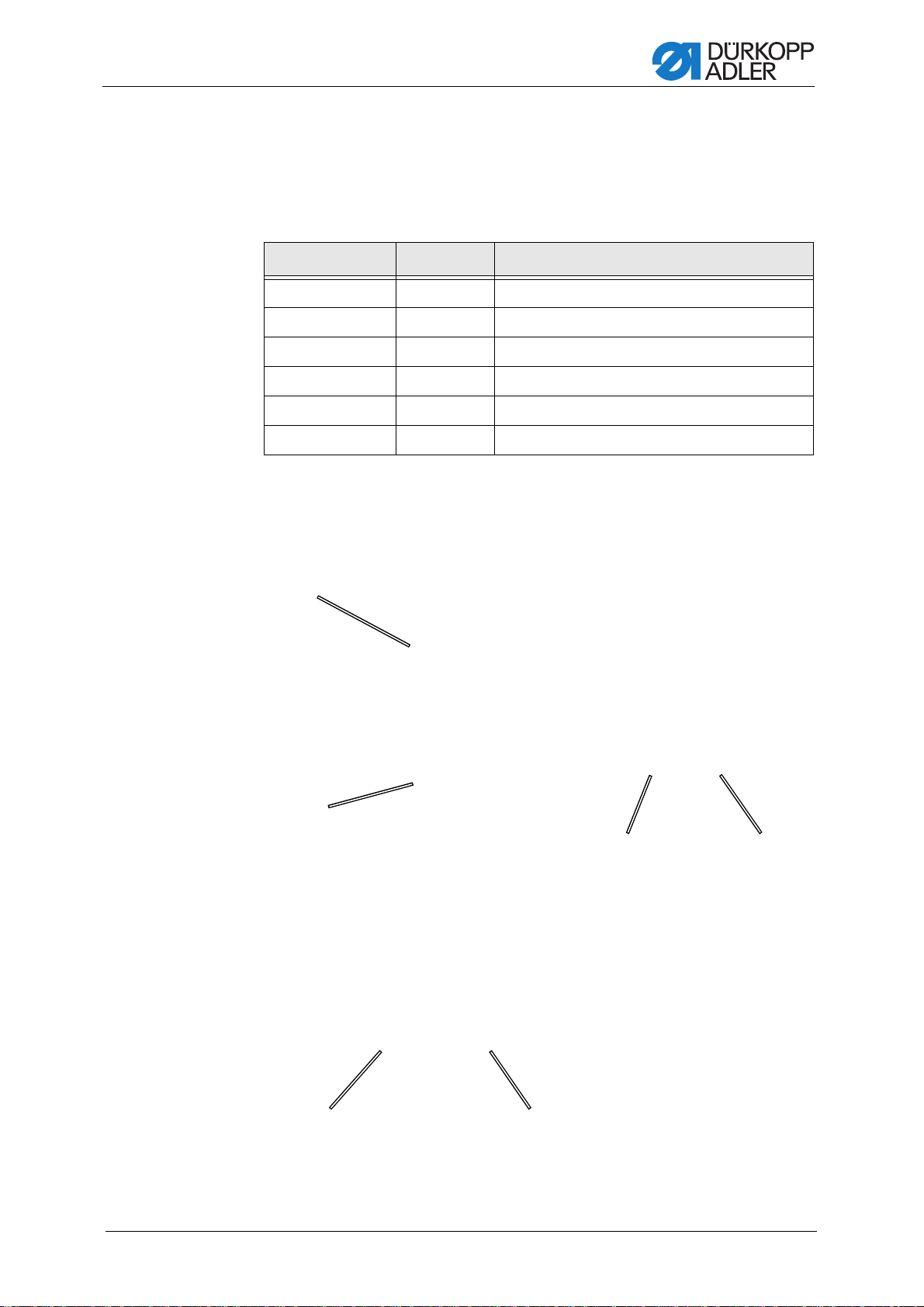
1 Kit components
Check whether the scope of delivery for parts set 0867 590094 is correct
prior to upgrade.
Material number Quantity Description
0867 100540 1 Thread lever protection
0867 110183 1 Thread guide
0867 110431 1 Threading procedure sticker
9835 901006 1 Antistatic armband
0791 550662 DE 1 BTSR sensor upgrade manual
0791 550662 EN 1 BTSR sensor upgrade manual
Abb. 1: Comparison of replacement parts
Additional Instructions 550-867 - 01.0 - 08/2017
3
Work preparation
①
(1) - Main switch
②
③
(2) - Lamp
(3) - Off button
(4) - UPS power unit
④
2 Work preparation
DANGER
Risk of injury from electric shock.
Switch off the machine and disconnect the power
plug before you upgrade the sensor.
Make sure the power plug cannot be accidentally
plugged back in.
Before performing the upgrade, the power needs to be switched off:
1. Turn the power switch (1) to the O position.
Abb. 2: Turning off the main switch
The lamp (2) on the UPS power unit (4) lights up.
Abb. 3: Switching off the power
4
Additional Instructions 550-867 - 01.0 - 08/2017

Work preparation
②
(2) - Lamp
2. Press and hold down the off button (3) for 3 seconds.
The lamp (2) goes out, the machine is powered down.
Abb. 4: Machine powered down
Additional Instructions 550-867 - 01.0 - 08/2017
5

Replacing the thread tension PCB
(1) - LED
①
3 Replacing the thread tension PCB
WARNING
Risk of injury from electricity
Double-check that the power is turned off.
Disconnect the machine from the power supply.
ATTENTION
Electrostatic charging may cause damage to equipment!
Work on the machine is ONLY permitted while wearing the antistatic
armband.
Handle the PCB only by its edges.
Do not push the PCB over a surface.
Checking the power
1. Open the control cabinet, the key for which is included with the machine.
2. Check whether LED (1) is lit up.
If LED (1) is NOT lit up, there is no power.
3. If LED (1) is still lit up, turn off the power, 2 Work preparation, p. 4.
Abb. 5: Checking the power
6
Additional Instructions 550-867 - 01.0 - 08/2017

Replacing the thread tension PCB
(2) - Antistatic armband
(3) - Clamp
(4) - Equipotential bonding
②
③
③
④
②
④
(5) - PCB
(6) - Plug
(7) - Screws
⑤
⑥
⑦
⑥
Putting on the antistatic armband
1. Fasten the antistatic armband (2) to the mechanic's arm.
2. Fasten the clamp (3) of the antistatic armband (2) to equipotential
bonding (4) on the control cabinet.
Abb. 6: Antistatic armband
Removing the PCB
1. Loosen all four screws (7) and remove the PCB (5).
2. Release the screws (6) on the plugs.
3. Pull off the plug (6).
Abb. 7: Removing the PCB
Additional Instructions 550-867 - 01.0 - 08/2017
7

Replacing the thread tension PCB
(6) - Plug
⑥
⑥
Abb. 8: Pulling off the plug
Inserting the PCB
1. Remove the new PCB from its antistatic bag.
2. Connect the plug (6) to the PCB.
3. Tighten the screws (6) on the plugs.
4. Screw the PCB (5) onto the stud bolts.
5. Tighten the PCB (5) to the stud bolts using the 4 screws (7).
Abb. 9: PCB packed in antistatic bag
8
Additional Instructions 550-867 - 01.0 - 08/2017

Dismantling the old parts
④
②
⑤
③
①
(1) - Screw
(2) - Head cover
(3) - Screw
(4) - Screws (concealed)
(5) - Thread lever protection
4 Dismantling the old parts
4.1 Dismantling the thread lever protection and thread clamp
Abb. 10: Dismantling thread lever protection
1. Loosen the screws (4) on the thread lever protection (5).
2. Remove the thread lever protection (5).
3. Loosen screw (1) on the head cover (2) and remove it.
4. Loosen screw (3) on the head cover (2).
5. Turn the head cover (2) back slightly.
6. Refit the screw (3) in order to keep the head cover (2) in its position.
Additional Instructions 550-867 - 01.0 - 08/2017
9

Abb. 11: Dismantling the thread clamp
⑥
⑦
(6) - Screw (7) - Thread clamp
①
(1) - Nut
Dismantling the old parts
7. Release screw (6) on the thread clamp (7).
8. Remove the thread clamp (7).
4.2 Dismantling the BTSR sensor and thread guide
Abb. 12: Dismantling the BTSR sensor
1. Loosen the nut (1) with a 7 mm wrench.
2. Remove the nut (1), washer and screw of the BTSR sensor.
10
Additional Instructions 550-867 - 01.0 - 08/2017

Dismantling the old parts
(2) - Screws (3) - Thread guide
②
③
Abb. 13: Dismantling the thread guide
3. Loosen the screws (2).
4. Remove the thread guide (3).
Additional Instructions 550-867 - 01.0 - 08/2017
11

5 Fitting the new parts
①
(1) - Screws (2) - Thread guide
②
Position correct, lying
fully flush against the
sewing machine arm
Too far away from the
sewing machine arm
5.1 Fitting the thread guide
Abb. 14: Installing the thread guide
Fitting the new parts
1. Attach the thread guide (2).
2. Tighten the screws (1).
3. The thread guide (2) must lie flush against the machine - bend the
thread guide (2) by hand if necessary.
Bend if required
Abb. 15: Position of thread guide
1. Check the position of the thread guide on the sewing machine arm.
2. If the position is correct, continue fitting the BTSR sensor.
12
Additional Instructions 550-867 - 01.0 - 08/2017

Fitting the new parts
(3) - Upper left area (4) - Right area
③
④
(3) - Nut
③
3. If the position is NOT correct, the thread guide will have to be bent
slightly.
Abb. 16: Bending the thread guide
4. Bend the thread guide using a pair of pliers in the upper left area (3).
5. Bend the thread guide back again afterwards in the right-hand area (4)
if necessary.
5.2 Installing the BTSR sensor
Abb. 17: Installing the BTSR sensor
1. Fit the nut (3), washer and screw of the BTSR sensor.
2. Tighten the nut (3) with a 7 mm wrench.
Additional Instructions 550-867 - 01.0 - 08/2017
13

5.3 Fitting the thread clamp
(1) - Thread clamp (2) - Screw
①
②
③
(3) - Sticker
(4) - Edges, parallel
④
Abb. 18: Fitting the thread clamp
Fitting the new parts
1. Insert the thread clamp (1) ensuring that the edge (4) of the thread
clamp is parallel to the edge (4) of the BTSR sensor.
2. Tighten the screw (2).
Abb. 19: Attaching the sticker
14
Attaching the threading procedure
1. Remove the white protective film from the sticker (3).
2. Place the sticker (3) into position.
3. Press down on the sticker (3) so it is firm.
4. Carefully remove the transparent mounting film.
Additional Instructions 550-867 - 01.0 - 08/2017

Fitting the new parts
④
②
⑤
③
①
(1) - Screw
(2) - Head cover
(3) - Screw
(4) - Thread lever
(5) - Screws (concealed)
(6) - Thread lever protection
⑥
5.4 Installing thread lever protection
Abb. 20: Installing thread lever protection
1. Attach the thread lever protection (6) so that it is located as far down
from the sensor and as much to the right as possible from this and
thereby does not collide with the thread lever (4) .
2. Check the thread lever protection (6) does not collide with the thread
lever (4).
3. Tighten the screws (5) on the thread lever protection (6).
4. Loosen the screw (3) on the head cover (2).
5. Position the head cover (2) so it is flush with the machine again.
6. Insert the screw (1) on the head cover.
7. Tighten screws (1) and (3).
Abb. 21: Positioning the thread lever protection
Additional Instructions 550-867 - 01.0 - 08/2017
15

Fitting the new parts
(1) - Thread guide (2) - Edges, parallel
①
②
(1) - Thread guide (2) - Edges, parallel
①
②
5.5 Machine following upgrade
To be able to use the sensor, it is important to pay a ttention to the following
points:
• the thread guide (1) must lie flush against the sewing machin e arm
5.1 Fitting the thread guide, p. 12.
• the edge (2) of the thread clamp must be parallel to the e dge (2) of
the BTSR sensor, 5.3 Fitting the thread clamp, p. 14
Abb. 22: bMachine with mechanical thread tension plate
Abb. 23: Machine with electronic thread tension plate
16
Additional Instructions 550-867 - 01.0 - 08/2017


DÜRKOPP ADLER AG
Potsdamer Str. 190
33719 Bielefeld
Germany
Phone +49 (0) 521 925 00
E-Mail: service@duerkopp-adler.com
www.duerkopp-adler.com
Subject to design changes - Part of the machines shown with additional equipment - Printed in Germany
© Dürkopp Adler AG - Additional Instructions - 0791 550662 EN - 01.0 - 08/2017
 Loading...