

Page 1
550-12-33/-34
Operating Instructions
Page 2

IMPORTANT
READ CAREFULLY BEFORE USE
KEEP FOR FUTURE REFERENCE
All rights reserved.
Property of Dürkopp Adler AG and protected by copyright. Any reuse
of these contents, including extracts, is prohibited without the prior
written approval of Dürkopp Adler AG.
Copyright © Dürkopp Adler AG 2017
Page 3

Table of Contents
1 About these instructions.................................. ..................................5
1.1 For whom are these instructions intended? ..........................................5
1.2 Representation conventions – symbols and characters........................6
1.3 Other documents............ ..................................... ..................................7
1.4 Liability ..................................................................................................8
2 Safety....................................................................................................9
2.1 Basic safety instructions........................................................................9
2.2 Signal words and symbols used in warnings.......................................11
3 Machine description..........................................................................15
3.1 Components of the machine ...............................................................15
3.2 Proper use............................................... ..................................... .......16
3.3 Declaration of Confor mi ty....................................................................17
4 Operation ...........................................................................................19
4.1 Preparing the machine for operation...................................................19
4.2 Switching on and off the machine .......................................................20
4.3 Inserting/changing the needle .............................................................22
4.4 Threading the needle thread.................................... ...........................24
4.5 Threading the hook thread.................................... ..............................27
4.6 Threading the reinforcement tape.......................................................30
4.6.1 Threading the reinforcement tape from the top...................................30
4.6.2 Threading the reinforcement tape from the bottom.............................33
4.7 Thread tension .................................................... ................................36
4.7.1 Setting the needle thread quantity.......................................................37
4.7.2 Setting the hook thread quantity ..........................................................39
4.7.3 Setting thread pre-tensioner/tape tensioner ........................................42
4.8 Switching the tape tensioner for the reinforcement tape on/off...........44
4.9 Setting the tape brake .........................................................................46
4.10 Locking the sewing feet at top dead center.........................................48
4.11 Setting the sewing foot stroke.............................................................49
4.12 Setting the sewing foot pressure.........................................................50
4.13 Using the knee button during sewing..................................................51
4.14 Push buttons on the machine arm................................................ ... ....53
4.15 Switching maximum stroke on and off.................................................54
4.16 Switching the edge cutter on and off...................................................55
4.17 Switching on and off the sewing lamp.................................................56
4.18 Setting the stitch length.......................................................................57
4.19 Sewing.................................................................................................58
5 Programming.....................................................................................61
5.1 The OP3000 control panel at a glance................................................61
5.2 Control operating modes.....................................................................65
Operating Instructions 550-12-33/34 - 00.0 - 08/2017 1
Page 4

Table of Contents
5.3 Manual mode.......................................................................................66
5.3.1 Adjusting additional parameters..........................................................68
5.3.2 Softkey menu and softkey functions in manual mode.........................70
5.3.3 Sewing in manual mode......................................................................72
5.4 Automatic mode ..................................................................................74
5.4.1 Softkey menu and softkey functions in automatic mode .....................76
5.4.2 Selecting a seam program in automatic mode....................................79
5.4.3 Sewing in automatic mode..................................................................80
5.4.4 Canceling a seam program in automatic mode...................................82
5.5 Teaching a new seam program (programming mode) ........................83
5.6 Edit mode............................................................................................90
5.6.1 Switching to edit mode........................................................................90
5.6.2 Creating a new seam program on the control panel ...........................91
5.6.3 Editing an existing seam program.......................................................99
5.6.4 Editing existing sewing sections........................................................102
5.6.5 Copying a seam program..................................................................105
5.6.6 Deleting a seam program..................................................................107
5.6.7 Mirroring a seam program.................................................................108
5.7 Ruffling support.................................................................................110
5.8 Smooth sewing - adjusting the stretch value.....................................113
5.9 Service mode ....................................................................................114
5.9.1 Opening the User configuration menu.....................................114
5.9.2 Setting the language .........................................................................114
5.9.3 Switching the signal tone during a seam section change on/off........115
5.9.4 Switching automatic progression left/right side on/off .......................116
5.9.5 Setting seam program cancellation using the pedal..........................117
5.9.6 Assigning a function to the knee button ............................................118
5.9.7 Setting the brightness of the display .................................................119
5.9.8 Setting the contrast of the display.....................................................120
5.9.9 Activating/deactivating the tilt sensor................................................120
5.10 Displaying the software version.........................................................122
5.11 Performing a software update ...........................................................123
6 Maintenance.....................................................................................125
6.1 Maintenance intervals .................................................... ...................126
6.2 Cleaning ............................................................................................127
6.3 Lubricating.........................................................................................128
6.3.1 Checking the lubrication of the machine head ..................................130
6.3.2 Checking the hook lubrication...........................................................131
6.4 Servicing the pneumatic system........................................................134
6.4.1 Setting the operating pressure..........................................................134
6.4.2 Draining the water condensation................ .......................................135
6.4.3 Cleaning the filter element.................................................................136
6.5 Parts list.............................................. ... .................................... ........137
2 Operating Instructions 550-12-33/34 - 00.0 - 08/2017
Page 5

Table of Contents
7 Setup ................................................................................................139
7.1 Checking the scope of delivery .........................................................139
7.2 Removing the transport locks ............................................................139
7.3 Assembling the reel stand.................................................................140
7.4 Setting the working height.................................................................142
7.5 Setting the pedal ...............................................................................144
7.6 Inserting the machine head...............................................................146
7.7 Tilting and erecting the machine head ..............................................148
7.8 Electrical connection .........................................................................150
7.9 Establishing equipotential bonding....................................................150
7.10 Pneumatic connection.......................................................................151
7.10.1 Assembling the compressed air maintenance unit............................151
7.10.2 Setting the operating pressure..........................................................152
7.11 Lubricating.........................................................................................153
7.12 Performing a test run.........................................................................155
8 Decommissioning ...........................................................................157
9 Disposal ...........................................................................................159
10 Troubleshooting..............................................................................161
10.1 Customer Service..............................................................................161
10.2 Messages of the software .................................................................161
10.3 Errors in sewing process...................................................................181
11 Technical data .................................................................................183
12 Appendix..........................................................................................187
12.1 Wiring diagram..................................................................................187
12.2 Tabletop drawing............................................................................... 193
Operating Instructions 550-12-33/34 - 00.0 - 08/2017 3
Page 6

Table of Contents
4 Operating Instructions 550-12-33/34 - 00.0 - 08/2017
Page 7

About these instructions
1 About these instructions
These instructions have been prepared with utmost care.
They contain information and notes intended to ensure long-term
and reliable operation.
Should you notice any discrepancies or if you have improvement
requests, then we would be glad to receive your feedback through
Customer Service ( p. 161).
Consider the instructions part of the product and store them in a
place where they are readily avai l able.
1.1 For whom are these instructions intended?
These instructions are intended for:
Service Instructions are supplied separately.
With regard to minimum qualification and other requiremen ts to be
met by personnel, please also follow the chapter Safety ( p. 9).
• Operators:
This group is familiar with the machine and has access to
the instructions. Specifically, chapter Operation ( p. 19)
is important for the operators.
• Specialists:
This group has the appropriate technical training for
performing maintenance or repairing malfunctions.
Specifically, the chapter Setup ( p. 139) is important for
specialists.
Operating Instructions 550-12-33/34 - 00.0 - 08/2017 5
Page 8

About these instructions
1.
2.
...
•
1.2 Representation conventions – symbols and characters
Various information in these instructions is represented or
highlighted by the following characters in order to facilitate easy
and quick understanding:
Proper setting
Specifies proper setting.
Disturbances
Specifies the disturbances that can occur from an incorrect setting.
Cover
Specifies which covers must be disassembled in order to access
the components to be set.
Steps to be performed when operating the machine (sewing
and equipping)
Steps to be performed for service, maintenance, and
installation
Steps to be performed via the software control panel
The individual steps are numbered:
First step
Second step
The steps must always be followed in the specified order.
Lists are marked by bullet points.
Result of performing an operation
Change to the machine or on the display/control panel.
Important
Special attention must be paid to this point when performing a step.
6 Operating Instructions 550-12-33/34 - 00.0 - 08/2017
Page 9

About these instructions
Information
Additional information, e.g. on alternative operating options.
Order
Specifies the work to be performed before or after a setting.
References
Reference to another section in these instructions.
Safety Important warnings for the user of the machine are specifically
marked. Since safety is of particular importance, hazard symbols,
levels of danger and their signal words are described separately
in the chapter Safety ( p. 9).
Location
information
If no other clear location information is used in a figure, indications
of right or left are always from the user's point of view.
1.3 Other documents
The machine includes components from other manufacturers.
Each manufacturer has performed a hazard assessment for these
purchased parts and confirmed their design compliance with
applicable European and national regulations. The proper use of
the built-in components is described in the corresponding manufacturer's instructions.
Operating Instructions 550-12-33/34 - 00.0 - 08/2017 7
Page 10

About these instructions
1.4 Liability
All information and notes in these instructions have been compiled
in accordance with the latest technology and the applicable
standards and regulations.
Dürkopp Adler cannot be held liable for any damage resulting
from:
• Breakage and damage during transport
• Failure to observe these instructions
• Improper use
• Unauthorized modifications to the machine
• Use of untrained personnel
• Use of unapproved parts
Transport
Dürkopp Adler cannot be held liable for breakage and transport
damages. Inspect the delivery immediately upon receiving it.
Report any damage to the last transport manager. This also
applies if the packaging is not damaged.
Leave machines, equipment and packaging material in the condition in which they were found when the damage was discovered.
This will ensure any claims against the transport company.
Report all other complaints to Dürkopp Adler immediately after
receiving the product.
8 Operating Instructions 550-12-33/34 - 00.0 - 08/2017
Page 11

Safety
2 Safety
This chapter contains basic information for your safety. Read the
instructions carefully before setting up or operating the machine.
Make sure to follow the information included in the safety instructions. Failure to do so can result in serious injury and property
damage.
2.1 Basic safety instructions
The machine may only be used as described in these instructions.
The instructions should be available at the machine's location at
all times.
Work on live components and equipment is prohibited. Exceptions
are defined in the DIN VDE 0105.
For the following work, switch off the machine at the main switch
or disconnect the power plug:
• Replacing the needle or other sewing tools
• Leaving the workstation
• Performing maintenance work and repairs
• Threading
Missing or faulty parts could impair safety and damage the
machine. Only use original parts from the manufacturer.
Transport Use a lifting c arriage or forklift to transpor t the machine. Raise the
machine max. 20 mm and secure it to prevent it from slipping off.
Setup The connecting cable must have a power plug approved in the
relevant country. The power plug may only be assembled to the
power cable by qualified specialists.
Obligations
of the operator
Operating Instructions 550-12-33/34 - 00.0 - 08/2017 9
Follow the country-specific safety and accident prevention regulations and the legal regulations concerning industrial safety and
the protection of the environment.
Page 12

Safety
All the warnings and safety signs on the machine must always be
in legible condition. Do not remove!
Missing or damaged warnings and safety signs must be replaced
immediately.
Requirements
to be met by
the personnel
Only qualified specialists may:
• Setting up the machine
• Performing maintenance work and repairs
• Performing work on electrical equipment
Only authorized persons may work on the machine and must first
have understood these instructions.
Operation Check the machine during operating for any externally visible
damage. Stop working if you notice any changes to the machine.
Report any changes to your supervisor. Do not use a damaged
machine any further.
Safety
equipment
Safety equipment should not be removed or deactivated. If it is
essential to remove or deactivate safety equipment for a repair
operation, it must be assembled and put back into operation
immediately afterward.
10 Operating Instructions 550-12-33/34 - 00.0 - 08/2017
Page 13
Safety
2.2 Signal words and symbols used in warnings
Warnings in the text are distinguished by color bars. The color
scheme is based on the severity of the danger. Signal words
indicate the severity of the danger.
Signal words Signal words and the hazard they describe:
Signal word Meaning
DANGER (with hazard symbol)
If ignored, fatal or serious injury will result
WARNING (with hazard symbol)
If ignored, fatal or serious injury can result
CAUTION (with hazard symbol)
CAUTION (with hazard symbol)
NOTICE (without hazard symbol)
If ignored, moderate or minor injury can result
If ignored, environmental damage can result
If ignored, property damage can result
Symbols The following symbols indicate the type of danger to personnel:
Symbol Type of danger
General
Electric shock
Operating Instructions 550-12-33/34 - 00.0 - 08/2017 11
Page 14
Symbol Type of danger
Puncture
Crushing
Environmental damage
Examples Examples of the layout of warnings in the text:
DANGER
Type and source of danger!
Consequences of non-compliance.
Measures for avoiding the danger.
Safety
This is what a warning looks like for a hazard that will result
in serious injury or even death if ignored.
WARNING
Type and source of danger!
Consequences of non-compliance.
Measures for avoiding the danger.
This is what a warning looks like for a hazard that could
result in serious or even fatal injury if ignored.
12 Operating Instructions 550-12-33/34 - 00.0 - 08/2017
Page 15

Safety
CAUTION
Type and source of danger!
Consequences of non-compliance.
Measures for avoiding the danger.
This is what a warning looks like for a hazard that could
result in moderate or minor injury if the warning is ignored.
NOTICE
Type and source of danger!
Consequences of non-compliance.
Measures for avoiding the danger.
This is what a warning looks like for a hazard that could
result in property damage if ignored.
CAUTION
Type and source of danger!
Consequences of non-compliance.
Measures for avoiding the danger.
This is what a warning looks like for a hazard that could
result in environmental damage if ignored.
Operating Instructions 550-12-33/34 - 00.0 - 08/2017 13
Page 16

Safety
14 Operating Instructions 550-12-33/34 - 00.0 - 08/2017
Page 17
Machine description
①
②
③
④
⑤
⑥
⑦
⑧
⑨
⑩
⑪
⑫
⑬
3 Machine description
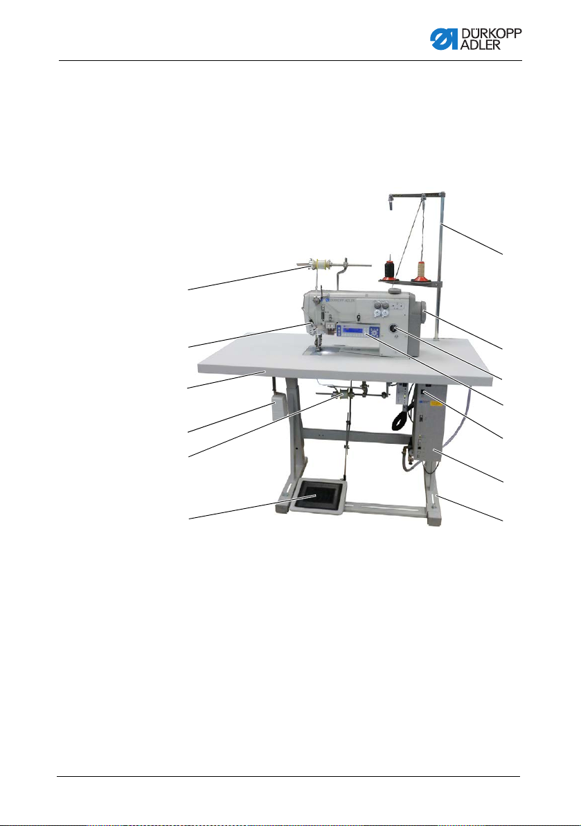
3.1 Components of the machine
Fig. 1: Components of the machine
(1) - Upper tape feeder
(2) - External sewing lamp
(3) - Tabletop
(4) - Knee button
(5) - Lower tape feeder
(6) - Pedal
(7) - Stand
(8) - Control
(9) - Main switch
(10)- Control panel OP3000
(11)- Oil-wick lubrication
(12)- Handwheel
(13)- Reel stand
Operating Instructions 550-12-33/34 - 00.0 - 08/2017 15
Page 18

Machine description
3.2 Proper use
WARNING
Risk of injury from live, moving and cutting
parts as well as from sharp parts!
Improper use can result in electric shock,
crushing, cutting and punctures.
Follow all instructions provided.
NOTICE
Non-observance will lead to property damage!
Improper use can result in material damage at the machine.
Follow all instructions provided.
The machine may only be used with sewing material that satisfies
the requirements of the specific application at hand.
The machine is intended only for use with dry sewing material.
The sewing material must not contain any hard objects.
The needle thicknesses permissible for the machine are listed in
the Technical data ( p. 183) chapter.
The seam must be completed with a thread that satisfies the
requirements of the specific application at hand.
The machine is intended for industrial use.
The machine may only be set up and operated in dry conditions on
well-maintained premises. If the machine is operated on premises
that are not dry and well-maintained, then further measures may
be required which must be compatible with DIN EN 60204-31.
Only authorized persons may work on the machine.
Dürkopp Adler cannot be held liable for damages resulting from
improper use.
16 Operating Instructions 550-12-33/34 - 00.0 - 08/2017
Page 19

Machine description
3.3 Declaration of Conformity
The machine complies with European regulations ensuring health,
safety, and environmental protection as specified in the declaration of conformity or in the declaration of incorporation.
Operating Instructions 550-12-33/34 - 00.0 - 08/2017 17
Page 20

Machine description
18 Operating Instructions 550-12-33/34 - 00.0 - 08/2017
Page 21

Operation
4 Operation
The operating sequence consists of several different steps.
Fault-free operation is necessary in order to achieve a good
sewing result.
4.1 Preparing the machine for operation
WARNING
Risk of injury from moving, cutting and sharp
parts!
Crushing, cutting and punctures are possible.
If possible, make preparations only when the
machine is switched off.
Complete the following steps in preparation of sewing before
starting to work:
• Inserting/changing the needle ( p. 22)
• Threading the needle thread ( p. 24)
• Threading the hook thread ( p. 27).
• Setting the thread tension ( p. 36)
• Threading the reinforcement tape ( p. 30)
Operating Instructions 550-12-33/34 - 00.0 - 08/2017 19
Page 22
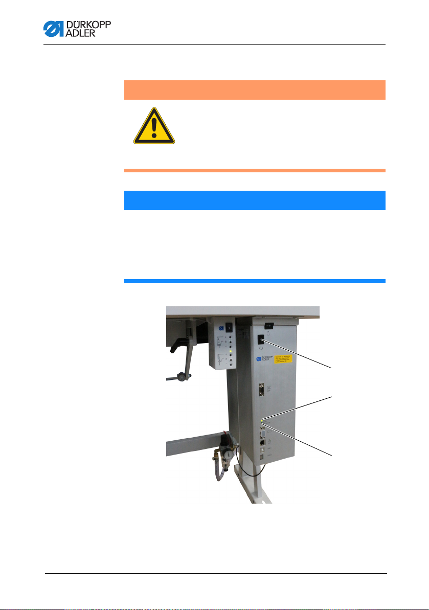
4.2 Switching on and off the machine
①
②
③
WARNING
Risk of injury from moving, cutting and sharp
parts!
Crushing, cutting and punctures are possible.
Do not sew unless the machine is fully assembled
and includes all safety devices.
NOTICE
Property damage may occur!
While the machine is referencing and while the needle is
down, the needle or the hook tip may break.
Do not switch the machine off unless the needle is up and
NOT plunged in the material.
Fig. 2: Switching on and off the machine
Operation
(1) - MESSAGE LED
(2) - POWER LED
(3) - Main switch
Operating Instructions 550-12-33/34 - 00.0 - 08/201720
Page 23

Operation
Switching on the machine
To switch on the machine:
1. Ensure that the needle is up and not plunged in the material
at the bottom.
Important
The needle must be at the top dead center, ensuring that
needle and hook tip cannot become damaged during
referencing.
2. Set the main switch (3) to position I.
POWER LED (2) illuminates, and the MESSAGE LED (1)
flashes briefly.
The splash screen appears on the display:
• On the left, the class
• On the right, the firmware
The machine performs a reference run and is ready for
sewing when the display shows the start screen.
The control remains in automatic mode ( p. 74) only for a
few seconds before switching to manual mode ( p. 66).
Switching off the machine
To switch off the machine:
1. Ensure that the needle is up and not plunged in the material
at the bottom.
Important
The needle must be at the top dead center, ensuring that
needle and hook tip cannot become damaged the next time
the machine is switched on and completes a reference run.
2. Set the main switch (3) to position 0.
The control panel shuts down. When the POWER LED (2)
goes out, the machine and the control are disconnected
from the power supply.
Operating Instructions 550-12-33/34 - 00.0 - 08/2017 21
Page 24

4.3 Inserting/changing the needle
①
②
③
④
⑤
WARNING
Risk of injury from moving, cutting and sharp
parts!
Crushing, cutting and punctures are possible.
Only insert or change the needle with the
machine switched off.
NOTICE
Property damage may occur!
Risk of missing stitches or damage to the thread when using
thinner needles. Risk of damage to the hook tip or the needle
when using thicker needles.
Correct the settings when using needles with a different
thickness.
Fig. 3: Inserting/changing the needle
Operation
(1) - Needle bar
(2) - Thread guide
(3) - Threaded pin
(4) - Needle
(5) - Groove
Operating Instructions 550-12-33/34 - 00.0 - 08/201722
Page 25

Operation
To change the needle:
1. Turn handwheel until the needle (4) is at the top dead center.
2. Loosen the threaded pin (3) through the hole in the thread
guide (2).
This requires that the thread guide (2) be assembled
completely straight to the needle bar (1).
3. Pull the needle (4) down and out.
4. Insert the new needle (4) into the hole in the needle bar (1)
until it reaches the end stop.
Important
Align the needle (4) in such a way that the groove (5) is pointing
to the rear.
5. Tighten the threaded pin (3) through the hole in the thread
guide (2).
Order
Always adjust the clearance between the hook and the needle (4)
after changing to a different needle thickness ( Service
Instructions).
Disturbance
An incorrect hook distance can cause the following disturbances:
• Changing to a thinner needle:
• Missing stitches
• Thread damage
• Changing to a thicker needle:
• Damage to the hook tip
• Damage to the needle
Operating Instructions 550-12-33/34 - 00.0 - 08/2017 23
Page 26
4.4 Threading the needle thread
①
②
③
WARNING
Risk of injury from moving, cutting and sharp
parts!
Crushing, cutting and punctures are possible.
Only thread the needle thread with the machine
switched off.
Fig. 4: Threading the needle thread (1)
Operation
(1) - Left thread reel plate
(2) - Tensioner
To thread the needle thread:
1. Fit the thread reel on the left thread reel plate (1).
2. Feed the needle thread through the thread guides as shown
and guide it around the tensioner (2).
Operating Instructions 550-12-33/34 - 00.0 - 08/201724
(3) - Thread guide
Page 27
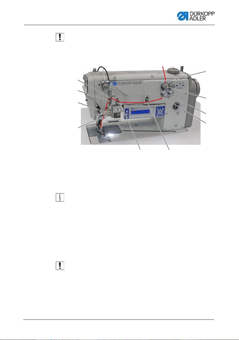
Operation
⑦
⑥
⑤
④
⑬
⑫
⑪
⑩
⑨⑧
Important
The unwinding bracket (3) must stand directly above the thread
reels.
Fig. 5: Threading the needle thread (2)
(4) - Thread lever
(5) - Needle thread regulator
(6) - Bracket
(7) - Thread guide
(8) - Thread guide
3. Feed the needle thread from top to bottom through the thread
guide (13).
4. Guide the needle thread counterclockwise around the
tensioner (12).
5. Guide the needle thread clockwise around the tensioner (11).
6. Feed the needle thread, as shown, through thread guides (8),
(9) and (10).
7. Feed the needle thread through the needle thread regulator (5)
and the thread lever (4).
Important
When feeding the thread through the needle thread regulator (5)
and the thread lever (4), pay attention as to how much needle
thread is needed to ensure proper stitch formation. The required
needle thread quantity defines the threading of the needle thread
( p. 37).
8. Feed the needle thread downwards behind the bracket (6).
9. Insert the needle thread through thread guide (7).
Operating Instructions 550-12-33/34 - 00.0 - 08/2017 25
(9) - Thread guide
(10)- Thread guide
(11)- Tensioner
(12)- Tensioner
(13)- Thread guide
Page 28
Operation
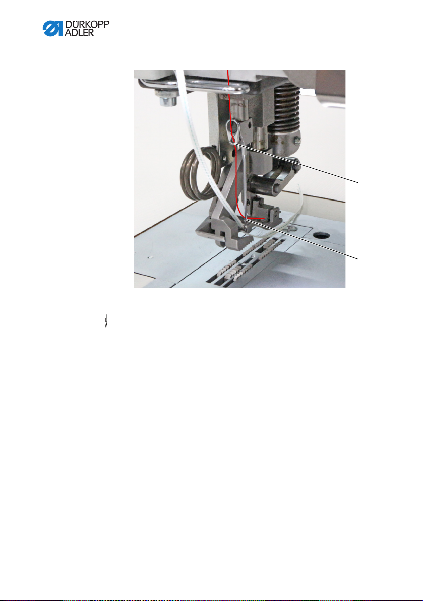
⑮
⑭
Fig. 6: Threading the needle thread (3)
(14)- Needle eye (15)- Thread guide
10. Insert the needle thread through thread guide (15).
11. Insert the needle thread through the needle eye (14) in such
a way that the loose end points downward/faces the hook.
Operating Instructions 550-12-33/34 - 00.0 - 08/201726
Page 29
Operation
③
①
②
4.5 Threading the hook thread
WARNING
Risk of injury from moving, cutting and sharp
parts!
Crushing, cutting and punctures are possible.
Only thread the hook thread with the machine
switched off.
Fig. 7: Threading the hook thread (1)
(1) - Tensioner
(2) - Thre ad guide
To thread the needle thread:
1. Fit the thread reel on the right thread reel plate (3).
Operating Instructions 550-12-33/34 - 00.0 - 08/2017 27
(3) - Righ t thread reel plate
Page 30
Operation
⑨
⑧
⑦
⑥
⑤
④
2. Feed the needle thread through the thread guides as shown
and guide it around the tensioner (1).
Important
The unwinding bracket (2) must stand directly above the thread
reels.
Fig. 8: Threading the hook thread (2)
(4) - Hook cover
(5) - Thre ad channel
(6) - Thre ad guide
3. Feed the hook thread from the top through the thread guide (9).
4. Guide the hook thread counterclockwise around the
tensioner (8).
5. Guide the hook thread clockwise around the tensioner (7).
6. Insert the hook thread through the 4 thread guides (6).
7. Open the hook covers (4) on the left and the right next to the
throat plate.
8. Open the thread channel (5).
9. Feed the hook thread through the thread channel (5).
10. Pull the hook thread from the rear under the cover plate of
the thread channel (5).
(7) - Tensioner
(8) - Tensioner
(9) - Thread guide
Operating Instructions 550-12-33/34 - 00.0 - 08/201728
Page 31

Operation
⑩
⑪
⑬
⑭
⑫
Fig. 9: Threading the hook thread (3)
(10)- Hook thread bobbin case retainer
(11)- Hook hole
(12)- Throat plate
11. Remove the cover plates to the right and left of the throat
plate (12).
12. Lift the hook thread bobbin case retainer (10) from its latching.
13. Turn the handwheel to position B in such a way that the thread
take-up disk (13) is set accordingly.
14. Insert the hook thread from the right to the left through the
holes of the hook thread guide (14).
15. Turn the handwheel until the hook holes (1 1) are accessible.
16. Insert the hook thread from the right to the left through the
hook holes (11) before pulling it out towards the rear by approx.
3 cm.
Fig. 10: Threading the hook thread (4)
(13)- Thread take-up disk
(14)- Hook thread guide
17. Press down and lock into place the hook thread bobbin case
retainer (10).
18. Insert the hook covers (4) again on the left and the right next
to the throat plate (12).
Operating Instructions 550-12-33/34 - 00.0 - 08/2017 29
Page 32

Operation
①②③
④
4.6 Threading the reinforcement tape
The reinforcement tape is used to reinforce the seam and support
ruffling. The reinforcement tape can be fed in 2 ways:
• Tape feeder at the top (at the machine head)
• Tape feeder at the bottom (under the tabletop)
The machine is equipped with either type of tape feeder. If fed
from the top, the reinforcement tape is sewn on top of the material.
If fed from the bottom, the reinforcement tape is sewn under the
material.
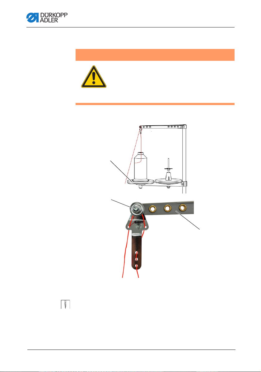
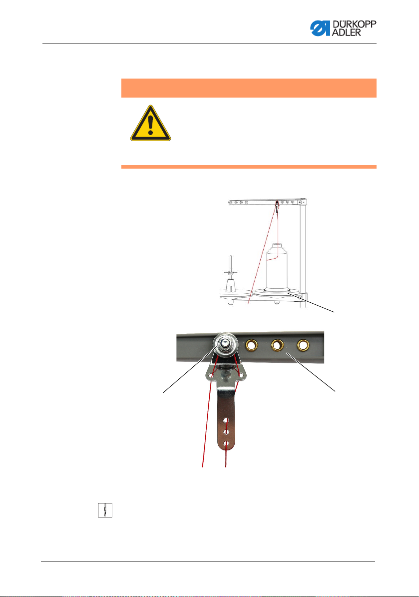
4.6.1 Threading the reinforcement tape from the top
Fig. 11: Threading the reinforcement tape from the top (1)
(1) - Bar
(2) - Screw
To thread the reinforcement tape from the top:
1. Loosen the screw (2) and pull it off the bar (1) towards the left
together with the brake element (3).
2. Fit the tape roll onto the bar (1).
3. Slip the brake element (3) back onto the bar (1).
4. Tighten the screw (2).
Now, the tape roll can no longer slip off the bar.
Operating Instructions 550-12-33/34 - 00.0 - 08/201730
(3) - Brake element
(4) - Screw
Page 33

Operation
⑥
⑤
⑦
⑧
⑨
5. Use the screw (4) to set how strongly the tape roll is supposed
to be braked ( p. 46).
Fig. 12: Threading the reinforcement tape from the top (2)
(5) - Thre ad guide
(6) - Bracket
(7) - Tape guide
6. Feed the reinforcement tape from the tape roll to the tape
guide (9) and thread it from top to bottom.
7. Feed the reinforcement tape clockwise through the
tensioner (8).
8. Feed the reinforcement tape from top to bottom through the
Operating Instructions 550-12-33/34 - 00.0 - 08/2017 31
tape guide (7).
(8) - Tensioner
(9) - Tape guide
Page 34

Operation
⑩
9. Feed the reinforcement tape downwards from the top behind
the bracket (6).
10. Guide the reinforcement tape IN FRONT OF the thread
guide (5) from the top.
DO NOT guide the reinforcement tape behind the thread
guide (5) to keep the reinforcement tape and the needle
thread from becoming entangled.
Fig. 13: Threading the reinforcement tape from the top (3)
(10)- Tape guide
11. Feed the reinforcement tape from top to bottom through the
tape guide (10).
The reinforcement tape has been fully threaded from the
top.
12. Guide the reinforcemen t ta pe towards the rear in the same
way as the needle thread.
Operating Instructions 550-12-33/34 - 00.0 - 08/201732
Page 35

Operation
③
⑤⑥
①
②
④
4.6.2 Threading the reinforcement tape from
the bottom
Fig. 14: Threading the reinforcement tape from the bottom (1)
(1) - Slot in the oil pan
(2) - Tape guide
(3) - Screw
To thread the reinforcement tape from the bottom:
1. Loosen the screw (5) and pull it off the bar (6) towards the left
together with the brake element (4).
2. Fit the tape roll onto the bar (6).
3. Slip the brake element (4) back onto the bar (6).
4. Tighten the screw (5).
Now, the tape roll can no longer slip off the bar.
5. Use the screw (3) to set how strongly the tape roll is supposed
to be braked ( p. 46).
6. Feed the reinforcement tape up from the tape roll to the tape
guide (2) and thread it.
7. Tilt the machine head ( p. 148).
8. Feed the reinforcement tape up through the slot in the oil
pan (1).
Operating Instructions 550-12-33/34 - 00.0 - 08/2017 33
(4) - Brake element
(5) - Screw
(6) - Bar
Page 36

Fig. 15: Threading the reinforcement tape from the bottom (2)
①
⑨⑧
⑦
Operation
(1) - Slot in the oil pan
(7) - Tape guide
9. Feed the reinforcement tape from the slot in the oil pan (1)
10. Feed the reinforcement tape clockwise through the
11. Insert the reinforcement tape through the tape guide (9).
through the tape guide (7).
tensioner (8).
Operating Instructions 550-12-33/34 - 00.0 - 08/201734
(8) - Tensioner
(9) - Tape guide
Page 37

Operation
⑩
⑪
Fig. 16: Threading the reinforcement tape from the bottom (3)
(10)- Throat plate
12. Feed the reinforcement tape, as shown, from the bottom
through the throat plate (10).
13. Guide the reinforcemen t ta pe towards the rear in the same
way as the needle thread.
14. Erect the machine head again ( p. 148).
Fig. 17: Threading the reinforcement tape from the bottom (4)
(11)- Lever
15. Loosen the lever (11) to set the rod of the bottom tape guide.
The bottom feeder must not impair free movement during
sewing.
16. Lock the lever (11) back into position.
Operating Instructions 550-12-33/34 - 00.0 - 08/2017 35
Page 38

Operation
4.7 Thread tension
Together with the hook thread tension, the needle thread tension
influences the final seam pattern. With thin sewing material,
excessive thread tension can lead to thread breakage.
Proper setting
The needle thread tension must be tighter than the hook thread
tension. To ensure the proper setting, the hook thread tensioner
is equipped with a spring made of thinner wire
Disturbance from incorrectly set thread tension
• Too tight: Crimping of the sewing material
• Too loose: Missing stitches
The thread tension is set at the OP3000 control panel ( p. 90).
If 100 % thread tension is insufficient, the thread pre-tension can
be supplemented ( p. 42). To this end, the tensioner elements
of the thread pre-tensioner are set closer together. The tensioner
elements of the thread pre-tensioner are, otherwise, always open.
Operating Instructions 550-12-33/34 - 00.0 - 08/201736
Page 39

Operation
very elastic less elastic
①
4.7.1 Setting the needle thread quantity
WARNING
Risk of injury from moving parts!
Crushing possible.
Switch off the machine before setting the needle
thread quantity.
The needle thread quantity released for stitch formation is determined by the position of the needle thread regulator. The required
needle thread quantity depends on the thickness of the sewing
material, the thread strength, and the seam type.
In addition, the threading procedure varies with the needle threads
and the types of seams used.
Fig. 18: Setting the needle thread quantity (1)
(1) - Thre ad lever
Proper setting
• Less elastic threads:
The thread lever (1) is visible just above the needle thread
regulator when at bottom dead center.
• Very elastic threads:
The thread lever (1) is visible just below the needle thread
regulator when at bottom dead center.
Operating Instructions 550-12-33/34 - 00.0 - 08/2017 37
Page 40

Fig. 19: Setting the needle thread quantity (2)
(a)
(b)
②②
③
①
③
Operation
(1) - Thre ad lever
(2) - Screw
To set the needle thread quantity:
1. Turn the handwheel until the thread lever (1) reaches its
bottom dead center.
2. Loosen the screws (2) of the needle thread regulator (3).
3. Move the needle thread regulator (3) to the correct position.
• For tight and normal seams (detail image (a)):
Feed the needle thread through the hole of the thread
lever (1) and then directly downwards.
• For elastic seams (detail image (b)):
Feed the needle thread through hole of the thread
lever (1) and then via the left bar of the needle thread
regulator (3).
4. Tighten the screws (2) for the needle thread regulator (3).
(3) - Needle thread regulator
Operating Instructions 550-12-33/34 - 00.0 - 08/201738
Page 41

Operation
①
②
③
4.7.2 Setting the hook thread quantity
The hook thread quantity released is determined by the position
of the hook thread take-up. The hook thread take-up adapts the
hook thread quantity to each set stitch length to allow for the best
possible stitch pull at any length and even with stitch condensing
enabled.
The hook thread take-up can be adjusted continuously on a scale
from 0 to 5. The larger the value, the greater the released thread
quantity and the more elastic the seam.
Proper setting
The proper setting is dependent on the stitch length and the seam
type.
You need to ensure, especially when applying extreme settings,
that the needle reliably plunges into the thread triangle:
• Elastic seam (3) with a very short stitch length = scale 5
• Tighter seam (1) with a significantly increased stitch length =
scale 0
Fig. 20: Setting the hook thread quantity (1)
(1) - Tight seam
(2) - Normal seam
Disturbance if hook thread quantity to too high
• Missing stitches
• Hook thread pops out of the thread take-up disk
Operating Instructions 550-12-33/34 - 00.0 - 08/2017 39
(3) - Highly elastic seam
(balloon stitch)
Page 42

Fig. 21: Setting the hook thread quantity (2)
④
⑤
⑥
⑨
⑩
⑦
⑧
Operation
(4) - Thre ad bobbin case retainer
(5) - Lower bar
(6) - Hole
(7) - Fron t edge
To set the hook thread quantity:
1. Tilt the machine head ( p. 148).
2. Loosen the screws (9).
3. Move the hook thread take-up (10).
• Tighter seam = move the front edge (7) towards the 0 on
the scale (8)
• More elastic seam = move the front edge (7) towards
the 5 on the scale (8)
(8) - Scale
(9) - Screw
(10)- Hook thread take-up
Operating Instructions 550-12-33/34 - 00.0 - 08/201740
Page 43

Operation
④
⑥
⑤
⑩
Important
Fig. 22: Setting the hook thread quantity (3)
(4) - Thread bobbin case retainer
(5) - Lower bar
Do not alter the height of the hook thread take-up (10).
The hole (6) must always remain above the lower bar (5) of
the thread bobbin case retainer (4).
4. Tighten the screws (9).
5. Erect the machine head ( p. 148).
(6) - Hole
(10)- Hook thread take-u p
Operating Instructions 550-12-33/34 - 00.0 - 08/2017 41
Page 44

Operation
②
①
③
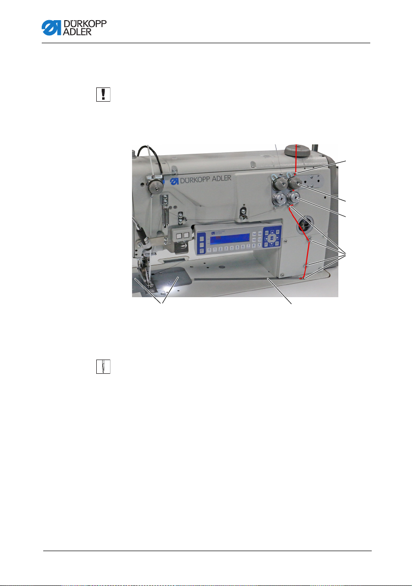
4.7.3 Setting thread pre-tensioner/tape tensioner
NOTICE
Production of loose stitches!
When sewing corners with active tensioner lift and
simultaneous sewing foot lift, the machine will produce a
loose stitch.
Do not activate the tensioner lift when lifting the sewing feet
unless the sewing feet are NOT lifted during the seam.
Fig. 23: Setting thread pre-tensioner/tape tensioner (1)
(1) - Tensioner element
(needle thread)
The additional tape tensioner of the reinforcement tape is set at
the tensioner elements in the same way as the needle and hook
thread tensioners.
Fig. 24: Setting thread pre-tensioner/tape tensioner (2)
(3) - Tensioner element
(upper tape tensioner)
(2) - Tens ioner element
(hook thread)
Operating Instructions 550-12-33/34 - 00.0 - 08/201742
Page 45

Operation
④
Fig. 25: Setting thread pre-tensioner/tape tensioner (3)
(4) - Tensioner element
(lower tape tensioner)
To increase the thread pre-tension/tape tension :
1. Turn the tensioner element (1)/(2)/(3)/(4) clockwise in the +
direction.
The tensioner element (1)/(2)/(3)/(4) is closed.
To reduce the thread pre-tension/tape tension:
1. Turn the tensioner element (1)/(2)/(3)/(4) counterclockwise in
the - direction.
The tensioner element (1)/(2)/(3)/(4) is opened.
For information on how to set a larger amount of thread in the
seam, see p. 37.
Information
The tape tensioner for the reinforcement tape is best set when
switched on, allowing you to test the setting directly during sewing.
For instructions on how to turn the tap e tensioner of the reinf orcement tape on/off, refer to ( p. 44).
Operating Instructions 550-12-33/34 - 00.0 - 08/2017 43
Page 46

Operation
①
②
4.8 Switching the tape tensioner for the
reinforcement tape on/off
Depending on its equipment, the machine may be equipped with
a lower or an upper tape feeder.
Fig. 26: Switching the tape tensioner for the reinforcement tape on/off (1)
(1) - Tensioner element (top)
Fig. 27: Switching the tape tensioner for the reinforcement tape on/off (2)
(2) - Tensioner element (bottom)
On both tape feeders, the reinforcement tape is fed through a
tensioner element (1)/(2), which can be closed and opened as
necessary.
The tape tensioner is switched off for ruffling values of 0-7.
The tape tensioner is switched on automatically for ruffling values
of 8 and higher; the button (3) will then light up. The tape tensioner
can be switched off at any time.
Operating Instructions 550-12-33/34 - 00.0 - 08/201744
Page 47

Operation
③
The tape tensioner is set in the same way as needle thread pretensioner and hook thread pre-tensioner ( p. 42).
Fig. 28: Switching the tape tensioner for the reinforcement tape on/off (3)
(3) - Button
To switch the tape tensioner on:
1. Press the button (3).
The tape tensioner is switched on.
To switch the tape tensioner off:
1. Press the button (3).
The tape tensioner is switched off.
Information
The ruffling value at which the tape tensioner is switched on
automatically can be adjusted on the OP3000 control panel
( p. 110).
Operating Instructions 550-12-33/34 - 00.0 - 08/2017 45
Page 48

Operation
②
①
③
4.9 Setting the tape brake
Information
If the reinforcement tape is not sewn straight relative to the seam,
the tape feeder may be too loose and/or the reinforcement tape
tension may be too low.
Ruffling is increased if the tape tension is too high and/or the tape
brake is set too tight.
The reinforcement tape tension can be set by adjusting the tape
tensioner ( p. 44). The tape brake regulates the tape feeder.
Depending on its equipment, the machine may be equipped with
a lower or an upper tape feeder for the reinforcement tape
( p. 30).
To ensure that the reinforcement tape is fed in a way that achieves
straight seam support and the desired ruffling value, the tape brake
must be set accordingly.
The principle that is used to brake the tape feeder is identical for
the upper and the lower feeder.
Fig. 29: Setting point in time for cutting (1)
(1) - Tape roll (top)
(2) - Screw
Operating Instructions 550-12-33/34 - 00.0 - 08/201746
(3) - Nut
Page 49

Operation
②
①
③
Fig. 30: Setting point in time for cutting (2)
(1) - Tape roll (bottom)
(2) - Screw
To set the upper/lower tape brake:
1. Loosen the nut (3).
2. To reduce the force of the tape brake, loosen the screw (2).
3. T o increase the force of the tape brake, tighten the screw (2).
4. To lock the screw (2) in position, tighten the nut (3).
(3) - Nut
Operating Instructions 550-12-33/34 - 00.0 - 08/2017 47
Page 50

Operation
①
4.10 Locking the sewing feet at top dead center
CAUTION
Risk of injury from moving parts!
Crushing possible.
Do not reach under the sewing feet.
Fig. 31: Locking the sewing feet at top dead center
(1) - Locking button
To lock the sewing feet at top dead center:
1. To lift the sewing feet, press and hold the pedal in position -1
or position -2.
The sewing feet remain lifted for as long as the pedal is kept
in position -1 or position -2.
2. Press the locking button (1) and keep it pressed.
3. Release the pedal (position 0).
4. Release the locking button (1).
The sewing feet are locked at top dead center.
Operating Instructions 550-12-33/34 - 00.0 - 08/201748
Page 51

Operation
①
②
To remove the lock:
1. Press the pedal to position -1.
2. Release the pedal (position 0).
The locking button (1) disengages, canceling the lock.
4.11 Setting the sewing foot stroke
The sewing foot stroke is adjustable over a range of 2-7 mm by
turning the adjusting wheel.
The increased sewing foot stroke can be switched on and off using
the left button ( p. 54).
Fig. 32: Setting the stroke height
(1) - Adjusting wheel (2) - Marking
To set the sewing foot stroke:
1. Set the sewing foot stroke:
• Increase the sewing foot stroke Turn the adjusting
wheel (1) counterclockwise
• Reduce the sewing foot stroke: Turn the adjusting
wheel (1) clockwise
The marking (2) indicates the selected stroke height.
Operating Instructions 550-12-33/34 - 00.0 - 08/2017 49
Page 52

4.12 Setting the sewing foot pressure
①②
NOTICE
Property damage may occur!
Damage to the sewing material.
Set the sewing foot pressure such that the sewing material
can neither slip nor become damaged.
Fig. 33: Setting the sewing foot pressure
Operation
(1) - Scre w (2) - Nut
To set the sewing foot pressure:
1. Loosen the nut (2).
2. Set the sewing foot pressure:
• Increase the sewing foot pressure:
Turn screw (1) clockwise
• Reduce the sewing foot pressure:
Turn screw (1) counterclockwise
3. Tighten th e nu t(2).
Important
Major changes to the sewing foot pressure require a recalibration
of the ruffling device ( Service Instructions).
Operating Instructions 550-12-33/34 - 00.0 - 08/201750
Page 53

Operation
①
②
4.13 Using the knee button during sewing
The knee button can be used to switch a function on and off during
sewing.
Fig. 34: Using the knee button during sewing (1)
(1) - Toggle switch (2) - Knee button
The position of the toggle switch (1) indicates whether the function
is switched on or off.
0 = function is switched off
1 = function is switched on
The function assigned to the knee button (2) at the factory is
Set selected ruffling value to 0 and vice versa.
Information
The knee button (2) can also be assigned other functions
( p. 118).
Operating Instructions 550-12-33/34 - 00.0 - 08/2017 51
Page 54

Fig. 35: Using the knee button during sewing (2)
②
(2) - Knee button
To use the knee button during sewing:
1. Press the knee button (2).
The ruffling value is reset to 0.
2. Press the knee button (2) again.
The previous ruffling value is restored.
Operation
Operating Instructions 550-12-33/34 - 00.0 - 08/201752
Page 55

Operation
②③①
4.14 Push buttons on the machine arm
The machine arm houses a panel with 2 push buttons and an
arrow button.
Fig. 36: Push buttons on the machine arm
(1) - Left button
(2) - Arrow button
(3) - Right button
The following functions have been stored:
• Left button: Quick stroke adjustment ( p. 54)
• Right button: Tape tensioner ( p. 44)
• Arrow button: Seam section change (in automatic mode,
p. 74)
Operating Instructions 550-12-33/34 - 00.0 - 08/2017 53
Page 56

Operation
①
4.15 Switching maximum stroke on and off
The left button can be used to switch the maximum stroke on and
off during sewing.
Fig. 37: Switching maximum stroke on and off
(1) - Button
To switch the maximum stroke on and off:
1. To switch to maximum stroke, press button (1).
The button (1) lights up, indicating that the function is
switched off.
2. To switch the maximum stroke off, press button (1) again.
The button (1) light goes out, indicating that the function is
switched off.
Operating Instructions 550-12-33/34 - 00.0 - 08/201754
Page 57

Operation
①
4.16 Switching the edge cutter on and off
CAUTION
Risk of injury at exposed blade!
There is a risk of sustaining injuries at the
exposed blades.
Do not reach into the cutting area.
Class 550-12-34 is equipped with an edge cutter. The edge cutter
is switched on and off using the button (1) on the OP3000 control
panel.
In manual mode, the edge cutter can be switched on and off at
any time ( p. 66). The top blade is designed such that it will
penetrate reliably even if activated during sewing.
Fig. 38: Switching the edge cutter on and off
(1) - Upper softkey
To switch the edge cutter on:
1. Press the upper softkey (1) .
To switch the edge cutter off:
1. Press the upper softkey (1) .
Information
The upper softkey (1) can also be assigned a different function.
In this case, the edge cutter can also be switched on and off in
Operating Instructions 550-12-33/34 - 00.0 - 08/2017 55
the softkey menu ( p. 70).
Page 58

Operation
②
④
③
⑤
⑦
⑥
①
4.17 Switching on and off the sewing lamp
The sewing lamp switches on and off independent of the main
switch.
Fig. 39: Switching on and off the sewing lamp
(1) - Switch
(2) - Button
(3) - Button
(4) - Button
To switch on the sewing lamp:
1. Set both switches (1) to position I.
The sewing lamp transformer is now powered on.
2. Press the button (6).
The sewing lamp illuminates.
3. Use the (5) or (7) button to set the brightness level.
To switch off the sewing lamp:
1. Press the button (6).
The sewing lamp goes out.
Operating Instructions 550-12-33/34 - 00.0 - 08/201756
(5) - Button
(6) - Button
(7) - Button
Page 59

Operation
2. Set both switches (1) to position 0.
The sewing lamp transformer is now powered off.
Information
The sewing lamp transformer allows for the connection of a second
LED light. The buttons (2), (3) and (4) are used to switch the
additional LED light on and off and to set the brightness level.
The scope of delivery does not include a second LED light.
4.18 Setting the stitch length
The stitch length is set at the OP3000 control panel ( p. 66).
In every seam program, the stitch length can be set individually
for each seam section.
Operating Instructions 550-12-33/34 - 00.0 - 08/2017 57
Page 60

4.19 Sewing
①
④
③
②
Fig. 40: Sewing (1)
Operation
WARNING
Risk of injury from moving parts!
Crushing injuries may be sustained while lowering
the sewing feet.
Do NOT put your hands under the lifted sewing
feet.
(1) - Position -2
(2) - Position -1
The machine offers 2 sewing modes:
• Manual mode ( p. 72)
• Automatic mode ( p. 80)
Use the pedal to start and control every sewing proce ss.
Initial situation
The pedal is released (position 0).
The machine is at a standstill.
The needle is up, and the sewing feet are down.
(3) - Position 0
(4) - Position 1
Operating Instructions 550-12-33/34 - 00.0 - 08/201758
Page 61

Operation
To position the sewing material:
1. Press the pedal to position -1.
The sewing foot is lifted.
2. Push the sewing material into the initial position.
3. Release the pedal (position 0).
The sewing foot lowers onto the sewin g mate ri al .
At seam beginning
To start a seam:
1. Press the pedal forward to position 1.
The machine sews. The speed increases the further forward
the pedal is pressed.
During sewing
To interrupt the seam:
1. Release the pedal (position 0).
The machine stops.
Needle and sewing foot are up / down.
To continue the seam:
1. Press the pedal forward to position 1.
The machine continues to sew.
At seam end
To finish the seam:
1. T o finish the seam, press the pedal completely backwards to
position -2.
The machine stops.
Needle and sewing feet are lifted and remain up as long as
the pedal is kept in the -2 position.
Operating Instructions 550-12-33/34 - 00.0 - 08/2017 59
Page 62

Operation
⑤
Fig. 41: Sewing (2)
(5) - Thread-pulling knife
2. Cut the reinforcement tape at the thread-pulling knife (5).
3. Remove the sewing material.
Operating Instructions 550-12-33/34 - 00.0 - 08/201760
Page 63

Programming
①
②
③ ⑤ ⑥
⑧
⑦
⑨
⑪
⑩
⑭⑬ ⑫
④
5 Programming
5.1 The OP3000 control panel at a glance
All software settings for the machine are performed using the
OP3000 control panel.
The control panel is equipped with the following buttons:
Fig. 42: The OP3000 control panel at a glance (1)
(1) - Upper softkey
(2) - Lower softkey
(3) - Plus/minus button
(4) - Arrow button
(5) - F button
(6) - Arrow button
(7) - S button
(8) - Arro w button
(9) - OK button
(10)- P Button
(11)- Arrow button
(12)- ESC button
(13)- Numeric buttons
(14)- Display
Operating Instructions 550-12-33/34 - 00.0 - 08/2017 61
Page 64

Buttons and functions
No. Button Function
Programming
Upper
①
softkey
Lower
②
softkey
③
④
F Function is different for each menu
⑤
⑥
S Function is different for each menu
⑦
⑧
OK • Confirm the settings
⑨
Assignment is different for each menu
Assignment is different for each menu
Switch between ruffling top and/or ruffling
bottom
• Selection to the left
• Back one menu level
• Decrease the value
• Scroll through the list (downwards)
• Selection to the right
• Activate the input
P • Start Edit mode
⑩
⑪
ESC • Cancel the function
⑫
• Increase the value
• Scroll through the list (upwards)
• Exit the menu
Operating Instructions 550-12-33/34 - 00.0 - 08/201762
Page 65

Programming
②
①
No. Button Function
0–16 • Set the ruffling value
⑬
Display and selection
The display shows menu items and value fields that you can
select and adjust.
Activated entry
The relevant activated entry is highlighted.
Fig. 43: The OP3000 control panel at a glance (2)
• Enter the parameter value (if the field for the
parameters is activated)
• Select the parameter shown on the display
Notice: There are no buttons 11, 13, and 15. In
order to, for instance, set the ruffling value 11,
press the two adjacent buttons, i.e. button 10
and button 12, at the same time.
(1) - Activated entry in a menu list (2) - Activated entry in a value field
You can use the arrow buttons to move from entry to entry:
• / in a list of menu items
• / for adjacent value fields
Operating Instructions 550-12-33/34 - 00.0 - 08/2017 63
Page 66

Programming
Back to menu level
Use to access the previous menu level.
Canceling in menu lists
If you press ESC in a menu list, this will bring you to the user level.
Changing values
In activated value fields, you can enter a value by using the
numeric buttons or change it incrementally using /.
If you have entered a value that is not within the sp ecified value
range, the software will automatically adopt from the value range
the limit value which is closest to your entry.
Confirm with OK
When pressing OK in a menu, you open the selected menu item
When pressing OK, you apply the activated entry.
Canceling value editing
If you press ESC when editing value fields, you can cance l the
entry without having to apply your changes.
Operating Instructions 550-12-33/34 - 00.0 - 08/201764
Page 67

Programming
5.2 Control operating modes
The control offers several different modes:
• Manual mode ( p. 66)
Manual mode is the simplest operating mode (seam program
number 000).
There are no seam programs and no seam sections in
manual mode.
Any changes made to parameters (e.g. stitch length or
thread tension, etc.) are applied immediately during the
sewing process.
• Automatic mode ( p. 74)
Automatic mode allows for the execution of seam programs
(seam program number 001 – 999).
The seam programs are divided into individual seam sections.
Each section is assigned its own specific parameters, e.g.
ruffling value, needle thread tension, etc.
Ruffling value and needle thread tension can be altered at any
time during the sewing process without effecting any
permanent changes to the seam program.
• Programming mode ( p. 83)
Programming mode allows for the teaching of new sewing
programs.
• Edit mode ( p. 90)
In Edit mode, new sewing programs can be created, edited,
deleted, copied and mirrored (right or left piece).
• Service mode
Service mode offers, for instance, functions such as changing
the language. For more information on service mode, refer to
the Service Instructions.
Information
The machine is capable of storing up to 999 seam programs with
a maximum of 30 seam sections each.
Operating Instructions 550-12-33/34 - 00.0 - 08/2017 65
Page 68

Programming
5.3 Manual mode
Fig. 44: Manual mode
Manual mode is the simplest operating mode, seam program
number 000. It does not contain any input for individual seam
sections. Any changes made to parameters are applied
immediately during the sewing process.
The following table shows the individual symbols of parameters
on the display and the functions of the buttons on the control panel.
When a parameter is selected, its color on the display changes.
When a parameter is changed, its new value is loaded immediately.
Button function and menu items on the display
Symbol Meaning
Upper softkey, can be assigned a softkey function
p. 70
• Press the upper softkey.
Class 550-12-34 features the symbol of the edge
cutter on the upper softkey, as this function has been
programmed at the factory.
Open the softkey menu p. 70.
• Press the lower softkey.
Seam program number
Value range: 000
000 signifies Manual mode.
/ to select the parameter.
•Use
/ to change the seam program number.
•Use
Or:
• Enter the seam program number directly using one of
the numeric buttons 0 – 9 and press OK to confirm if
necessary.
The control switches to Automatic mode
Operating Instructions 550-12-33/34 - 00.0 - 08/201766
Page 69

Programming
Symbol Meaning
Ruffling type and ruffling value
The ruffling type and the ruffling value are shown on
the display.
Caution: While it cannot be selected, this selection can
be changed.
• To select the ruffling type, press the button.
• : Ruffling top and bottom
• : Ruffling top
• : Ruffling bottom
0–16
Setting the ruffling value
Value range: 0-16
Notice: There are no buttons 11, 13, and 15. In order
to, for instance, set the ruffling value 11, press the two
adjacent buttons, i.e. button 10 and button 12, at the
same time.
• To change the ruffling value, press the numeric
button/s.
Select possible ruffling types:
• Ruffling top and bottom
• Ruffling top
• Ruffling bottom
Stitch length
Value range: 3.0 – 6.0 mm
/ to select the parameter.
•Use
/ to change the stitch length.
•Use
Needle thread tension
Value range: 1– 99, preset at 40 %
•Use
/ to select the parameter.
/ to change the needle thread tension.
•Use
Setting the parameters
p. 68
Stitch counter of the current seam section
After the thread has been cut, the display is retained.
Measurement restarts when sewing starts again.
F, S No function assigned
Operating Instructions 550-12-33/34 - 00.0 - 08/2017 67
Page 70

Programming
Symbol Meaning
ESC •Press ESC to end a function/exit the menu.
The changes remain in effect when you exit the
menu.
OK OK
Left button Switch maximum stroke on and off (quick stroke
Right button Tape tensioner for the reinforcement tape p. 44
•Press OK to confirm a selection/open the menu
adjustment) p. 54
• To sw itch maximum stroke on/of f, press the left button .
• To switch the tape tensioner on/off, press the right
button.
5.3.1 Adjusting additional parameters
To adjust the additional parameters:
1. Use ◄/► to switch to the selection.
2. Confirm with OK.
The menu opens.
You can adjust the following parameters in this menu:
Symbol Meaning
Hook thread tension (Thr. Tens. Bot)
Set hook thread tension
Adjusting smooth sewing/stretch value (Flat Sew)
Adjust stretch value
Maximum speed (Max Speed)
Define maximum speed/number of stitches
Operating Instructions 550-12-33/34 - 00.0 - 08/201768
Page 71

Programming
Symbol Meaning
Stitch condensing at seam beginning (StitchCond
Beg)
Checkbox selected = function is switched on
Checkbox deselected: function is switched off
Stitch condensing at seam end (StitchCond End)
Checkbox selected = function is switched on
Checkbox deselected: function is switched off
Lifting the sewing feet (Foot)
FL AtStop: Lift sewing automatically when sewing
stops
0 = deactivated
1 = activated
• Activate/deactivate using
to exit the submenu.
•Use
Ruffling support (Ruffl. Support)
The following additional settings can be activated to
support ruffling:
• Needle thread tension (Thr. Tens. Top)
• Hook thread tension (Thr. Tens. Bot)
• Tape tension (Tape Tension)
p. 110
/.
3. Use ▲/▼ to select the desired parameter.
4. Press the OK button to activate or deactivate the parameter
▲/▼ to edit the value and confirm the change by
or use
pressing OK.
5. To exit the menu, p ress the ESC button.
The changed values are stored.
Operating Instructions 550-12-33/34 - 00.0 - 08/2017 69
Page 72

Programming
①
②
5.3.2 Softkey menu and softkey functions in manual mode
Fig. 45: Softkey menu and softkey functions in manual mode (1)
(1) - Upper softkey (2) - Lower softkey
The softkey buttons serve the following functions:
• upper softkey (1): The button can be assigned a softkey func-
tion for quick access
• lower softkey (2): quick access to the softkey menu during
the sewing process
The following functions are found in the softkey menu in Manual
mode:
Symbol Meaning
Manual stitch condensing on
• Press the button 1 and keep it pressed
Stitch condensing on or off
• Press button 2
Stitch condensing is switched on or off
Switch maximum stroke on and off (quick stroke
adjustment)
This function is only available during sewing
• To switch maximum stroke n/off, press button 3
Needle position up or down
• Press button 4
The needle is up or down when sewing stops
Operating Instructions 550-12-33/34 - 00.0 - 08/201770
Page 73

Programming
Symbol Meaning
Creating a new seam program
• Press button 5
no softkey function assigned (factory setting, button 6)
Go to page 2
• Press button 7
Tape tensioner
• Press button 1
Edge cutter
• Press button 2
Return to page 1
• Press button 7
Opening the softkey menu
To open the softkey menu:
1. Press the lower softkey .
The display switches to:
Fig. 46: Softkey menu and softkey functions in Manual mode (2)
Switching a softkey function on/off
To switch a softkey function on and off:
1. Press button 1/2/3/4/5 under the desired softkey function.
2. To exit the softkey menu, press the lower softkey again.
Operating Instructions 550-12-33/34 - 00.0 - 08/2017 71
Page 74

Programming
Assigning a softkey function to the upper softkey (1)
Information
The upper softkey can only be assigned one new softkey function
at a time.
To assign a softkey function to the upper softkey (1):
1. Press button 1/2/3/4/5 under the desired softkey function and
the upper softkey (1) at the same time.
The function is assigned to the upper softkey (1) and can
subsequently be called up using this softkey.
Removing a softkey function from the upper softkey
To remove the softkey function from the upper softkey:
1. Press the upper softkey (1) and button 6 at the same time.
The upper softkey (1) is no longer assigned a function.
5.3.3 Sewing in manual mode
To sew in manual mode:
Sewing without ruffling
1. Press button 0 to set the ruffling value to 0.
2. If necessary, change values such as stitch length and thread
tension.
3. Press the pedal forward to position 1 and sew.
Information
If the seam is not entirely smooth, adjust the stretch value for the
ruffling value of 0 ( p. 113).
Operating Instructions 550-12-33/34 - 00.0 - 08/201772
Page 75

Programming
Sewing with ruffling
1. Release the pedal (position 0).
2. To select the ruffling type if necessary, press the button.
• : Ruffling top and bottom
• : Ruffling top
• : Ruffling bottom
The set ruffling value is shown on the display.
3. If necessary, use the numeric buttons 0 – 16 to change the
ruffling value.
The set ruffling value is shown on the display below the
ruffling type.
4. Press the pedal forward to position 1 and continue sewing.
The seam will be sewn using the altered parameter value.
Adjusting parameters during sewing
To adjust parameters during sewing:
1. Release the pedal (position 0).
2. Change the desired parameter on the control panel (( p. 68)).
3. Press the pedal forward to position 1 and sew.
The seam will be sewn using the altered parameter value.
Finishing sewing
To finish a seam:
1. T o finish the seam, press the pedal completely backwards to
position -2.
The machine stops.
Needle and sewing feet are lifted and remain up as long as
the pedal is kept in the -2 position.
2. Cut the reinforcement tape at the thread-pulling knife ( p. 59).
3. Remove the sewing material.
Operating Instructions 550-12-33/34 - 00.0 - 08/2017 73
Page 76

Programming
5.4 Automatic mode
Automatic mode includes all seam programs from 001–999.
The following table shows the individual symbols on the display
and the functions of the buttons on the control panel:
Button function and menu items on the display
Symbol Meaning
Upper softkey, can be assigned a softkey function
• Press the upper softkey.
Open the softkey menu p. 76.
• Press the lower softkey.
Seam program number
Value range: 001– 999
Automatic mode allows for the execution of seam
programs 001-999.
/ to select the parameter.
•Use
/ to change the seam program number.
•Use
OR:
• Enter the seam program number directly using one of
the numeric buttons 0 – 9 and press OK to confirm if
necessary.
The control switches to automatic mode, and the
corresponding seam program is active:
Right/left piece
/to select between the right/left piece
•Use
(if programs exist for both).
Stitch length
Value range: 3.0 – 6.0 mm
•Use
/ to select the parameter.
•Use
/ to change the stitch length.
Needle thread tension
Value range: 1– 99
•Use
/ to select the parameter.
/ to change the needle thread tension.
•Use
Operating Instructions 550-12-33/34 - 00.0 - 08/201774
Page 77

Programming
Symbol Meaning
0–16 Setting the ruffling value 0-16
Notice: There are no buttons 11, 13, and 15. In order
to, for instance, set the ruffling value 11, press the two
adjacent buttons, i.e. button 10 and button 12, at the
same time.
Bar
Length per seam section in mm,
or a dash (-) if no automatic seam
section progression is active.
Stitches are counted down for
every seam section.
OK OK
•Press OK to confirm a selection/open the menu
ESC Exiting automatic mode
This step cannot cancel the sewing of a started seam.
p. 82
F, S No function assigned
Arrow button
• If no automatic progression is active, use the arrow
button to switch to the next seam section.
Left button Switch maximum stroke on and off (quick stroke
Right button Tape tensioner for the reinforcement tape p. 44
Operating Instructions 550-12-33/34 - 00.0 - 08/2017 75
adjustment) p. 54
• To switch maximum stroke on/off, press the left
button.
• To switch the tape tensioner on/off, press the right
button.
Page 78

Programming
①
②
Information
If the stitch numbers programmed for each seam section are not
displayed in automatic mode, the function StitchCount must
be activated.
If the stitch counter is deactivated, the seam section change will
be deactivated following the programmed number of stitches.
No stitch counts are displayed for the individual seam sections,
and no automatic seam section change is performed following the
completion of the programmed stitch count. A seam section
change can then only be executed manually using the arrow
button.
The Count Stitches function is activated/deactivated using
the softkey menu ( p. 76).
5.4.1 Softkey menu and softkey functions in automatic mode
Fig. 47: Softkey menu and softkey functions in automatic mode (1)
(1) - Upper softkey (2) - Lower softkey
The softkey buttons serve the following functions in automatic
mode:
• upper softkey (1): The button can be assigned a softkey func-
tion for quick access
• lower softkey (2): quick access to the softkey menu during
the sewing process
Operating Instructions 550-12-33/34 - 00.0 - 08/201776
Page 79

Programming
The following functions are found in the softkey menu in automatic
mode:
Symbol Meaning
Manual stitch condensing on
• Press button 1 and keep it pressed for manual stitch
condensing
Stitch condensing on or off
• Press button 2
Stitch condensing will be switched on or off the next
time the seam section changes
Resetting the piece counter
• Press button 3
Stitch counting on or off
If the function is switched off in the softkey menu, the
programmed number of stitches will NOT be shown in the
seam sections.
• Press button 4.
Before sewing: Creating a new seam program
• Press button 5
During sewing: Half stitch
• Press button 5
no softkey function assigned (factory setting, button 6)
Go to page 2
• Press button 7
Switch tape tensioner on/off
• Press button 1
Return to page 1
• Press button 7
Operating Instructions 550-12-33/34 - 00.0 - 08/2017 77
Page 80

Programming
Opening the softkey menu
To open the softkey menu:
1. Press the lower softkey (2).
The display switches to:
Fig. 48: Softkey menu and softkey functions in automatic mode (2)
Switching a softkey function on/off
To switch a softkey function on and off:
1. Press button 1/2/3/4/5 under the desired softkey function.
The symbol is highlighted.
2. To exit the softkey menu, press the lower softkey again.
Assigning a softkey function to the upper softkey (1)
Information
The upper softkey can only be assigned 1 softkey function at
atime.
To assign a softkey function to the upper softkey (1):
1. Press button 1/2/3/4/5 under the desired softkey function and
the upper softkey (1) at the same time.
The function is assigned to the upper softkey (1) and can
subsequently be called up using this softkey.
Operating Instructions 550-12-33/34 - 00.0 - 08/201778
Page 81

Programming
Removing a softkey function from the upper softkey
To remove the softkey function from the upper softkey:
1. Press the upper softkey (1) and button 6 at the same time.
The upper softkey (1) is no longer assigned a function.
5.4.2 Selecting a seam program in automatic mode
To select a seam program in automatic mode:
1. Use
2. Use
◄/► to switch to the selection.
▲/▼ to select the seam program number 001 or another
one (if available).
The seam program number must not be 000, as this number
signifies manual mode rather than a seam program.
The control switches to automatic mode, and the display
switches to:
3. Adjust the parameters on the display if necessary ( p. 90).
Fig. 49: Selecting a seam program in automatic mode
Information
If you wish to execute the seam program of a left/right piece and
both pieces have already been created, select the desired piece
now:
4. Use
5. Use
◄/► to switch to the selection.
▲/▼ to select the desired piece L/R.
L = left piece
R = right piece
Operating Instructions 550-12-33/34 - 00.0 - 08/2017 79
Page 82

Programming
①②
If a left piece has not yet been created, the existing right piece
can be mirrored at any time ( p. 108).
You can now execute the selected seam program ( p. 80).
5.4.3 Sewing in automatic mode
After selecting a seam program between 001 and 999, you will be
in Automatic mode.
To sew in Automatic mode:
1. Select the seam program ( p. 79).
2. Press the pedal forward to position 1 and sew.
The display switches to:
Fig. 50: Sewing in automatic mode (1)
(1) - Bar (2) - Curr ent seam section
The parameter values for the current sea m section ar e shown in
the upper half of the display.
Fig. 51: Sewing in automatic mode (2)
The bottom half of the display shows the progress of the seam
program.
The bar shows half the current seam section in bold.
The number (2) under the current seam section (3) shows the
outstanding stitches.
Fig. 52: Sewing in automatic mode (3)
Operating Instructions 550-12-33/34 - 00.0 - 08/201780
Page 83

Programming
The bar is shown fully in bold when the seam section has been
completed.
The following table lists the button functions that can be performed
in the course of the sewing process.
Button/Pedal Function
Open and close the softkey menu, p. 76.
• To open the softkey menu, press the lower softkey.
/
/
0–16 Setting the ruffling value 0-16
OK OK
ESC Exit the menu
F, S No function assigned
Left button Switch maximum stroke on and off (quick stroke
Right button Tape tensioner for the reinforcement tape p. 44
Next/previous seam section/return to beginning of
seam section
Correction of the thread tension
Notice: There are no buttons 11, 13, and 15. In order
to, for instance, set the ruffling value 11, press the two
adjacent buttons, i.e. button 10 and button 12, at the
same time.
• Press the OK to confirm a selection/open the menu
Arrow button
• Use the arrow button to switch to the next seam
section.
adjustment) p. 54
• To switch maximum stroke on/off, press the left
button.
• To switch the tape tensioner on/off, press the right
button.
3. Sew the programmed stitches.
Operating Instructions 550-12-33/34 - 00.0 - 08/2017 81
Page 84

Programming
The machine counts down the programmed stitches while
sewing and will NOT stop automatically when all stitches
have been sewn. The machine keeps sewing for as long
as the pedal is kept in the 1 position. The stitches sewn and
indicated on the display are preceded by a minus sign.
4. T o finish the seam, press the pedal completely backwards to
position -2.
The machine stops and returns to the beginning of the seam
program/to the other side (if the left and the right side are
sewn one after the other).
Needle and sewing feet are lifted and remain up as long as
the pedal is kept in the -2 position.
5. Cut the reinforcement tape at the thread-pulling knife ( p. 59).
6. Remove the sewing material.
5.4.4 Canceling a seam program in automatic mode
To cancel a seam program in automatic mode:
1. Press the pedal fully back to position -2.
The machine remembers the spot where sewing w as
interrupted. The seam program will resume from this
position when sewing continues.
2. To cancel the seam program completely, press the pedal
completely backwards to position -2 again.
The seam program is canceled.
Operating Instructions 550-12-33/34 - 00.0 - 08/201782
Page 85

Programming
5.5 Teaching a new seam program
(programming mode)
You can create new seam programs using the ( p. 91) control
panel OR by teaching.
Teaching means to sew the desired seam sections and
manually adjust the seam section parameters in the process.
The parameters for the seam program can subsequently be
adapted.
Information
Every new seam program is based on the preset values that have
been assigned at the factory and can only be changed in service
mode ( Service Instructions).
To teach a new seam program:
Assigning a new seam program number
1. To open the softkey menu in automatic/edit/manual mode,
press the lower softkey .
The softkey menu appears.
2. To create a new seam program, press the button.
The display switches to:
Fig. 53: Teaching a new seam program (programming mode)(1)
The display shows the next available seam program number .
3. Seam program number
• Confirm with OK or
• Change using
• Re-enter using the numeric buttons 0-9
Operating Instructions 550-12-33/34 - 00.0 - 08/2017 83
▲/▼ or
Page 86

Programming
Information
The machine displays only available seam program slots/accepts
only available seam program slots entered numerically.
4. Confirm with OK.
The display switches to:
Fig. 54: Teaching a new seam program (programming mode)(2)
The new seam program has been created, but does not yet
contain any individual settings.
Defining a sideless/left/right piece
5. Use to switch to the selection.
6. If the seam program is intended for a left/right piece, set the
desired side using
▲/▼.
L = left piece
R = right piece
If you do not change the setting
-, the machine will create a
new seam program for a sideless piece.
Important
Once the seam program has been saved, this setting can no longer
be changed.
7. Press the upper softkey Teach-In .
The display switches to:
Fig. 55: Teaching a new seam program (programming mode)(3)
Operating Instructions 550-12-33/34 - 00.0 - 08/201784
Page 87

Programming
Information
The upper softkey has been assigned the function Count
Stitches. In this example, the stitch count is switched off and,
consequently, struck through. When the switch count is switched
off, the stitches programmed for each seam section during
teaching will no longer be displayed during the sewing of the seam
program.
When the stitch count is switched on, the length of the seam
section is counted down in stitches.
8. To activate the stitch count, press the upper softkey.
The stitch count is activated and no longer struck through on
the display.
Important
If the number of stitches is still not being displayed in automatic
mode, activate the stitch count in the softkey menu ( p. 76).
Adjusting the parameters on the display
You can adjust the following parameters for the current seam
section directly on the display:
Symbol Meaning
Ruffling type and ruffling value
The ruffling type and the ruffling value are shown on
the display.
Caution: While it cannot be selected, this selection can
be changed.
• To select the ruffling type, press the button.
• : Ruffling top and bottom
• : Ruffling top
• : Ruffling bottom
• To change the ruffling value, press the numeric
button/s.
Operating Instructions 550-12-33/34 - 00.0 - 08/2017 85
Page 88

Programming
Symbol Meaning
Stitch length of the current seam section
Value range: 3.0 – 6.0 mm
/ to select the parameter.
•Use
/ to change the stitch length.
•Use
Needle thread tension of the current seam section
Value range: 1– 99
•Use
/ to select the parameter.
/ to change the needle thread tension.
•Use
9. Use ◄/► to switch to the / selection.
10. Use
▲/▼ or the numeric buttons to adjust the value.
Adjusting additional parameters in the seam section menu
You can adjust the following parameters for the current seam
section:
Symbol Description
Stitch counter (StitchCount)
Enter the desired number of stitches for the seam section
• Value: 0000-9999
Hook thread tension (Thr.Tens.Bot)
• Setting the hook thread tension
Maximum speed (Max Speed)
• Set maximum speed
Lifting the sewing feet at the end of the seam program
(Foot Lifted)
• Switching sewing foot lifting on/off
Needle position at the end of the seam program
(Needle Up)
• Set needle up/down
Edge cutter (EdgeTrimmer)
• Activate/deactivate the edge cutter
Operating Instructions 550-12-33/34 - 00.0 - 08/201786
Page 89

Programming
11. Use ◄/► to switch to the selection.
12. Confirm with OK.
The seam section menu appears.
13. Use
▲/▼ to select the desired parameter of the first seam
section.
14. Press the OK button to activate or deactivate the parameter
▲/▼ to edit the value, enter new values using the
or use
numeric buttons and confirm the change by pressing OK.
Use ◄ to exit the submenu.
The changed values are stored immediately.
15. To exit the seam secti o n me nu , press the ESC button.
The changed values are stored immediately.
16. Insert the sewing material.
17. T o sew the 1st seam section up to the desired position, press
the pedal forward to position 1.
Information
If you already entered a number of stitches for this seam section
in the seam section menu, the stitches sewn now will be added
to this value.
The only way to correct/adjust this new number of stitches is by
using the seam section menu.
Setting softkey functions for the current seam section
18. Press the lower softkey to switch a softkey function on or of f.
The softkey menu opens.
19. Switch the following softkey functions on and off as needed
for the current seam section in the softkey menu:
• Stitch count (button 1)
• Tape tensioner (button 2)
• Edge cutter (button 3)
Every softkey function that is struck through is deactivated.
Operating Instructions 550-12-33/34 - 00.0 - 08/2017 87
Page 90

Programming
Adding new seam sections
20. To switch to the 2nd seam section, press the
▲ button.
The 2nd seam section is created automatically.
21. Repeat steps 3-11 for all other seam sections.
Finishing and saving the new seam program
There are 2 ways to finish and save the new seam program:
22. When all seam sections have been sewn and adjusted,
press the pedal fully back to position -2.
The settings for the seam sections of the new seam
program are stored.
P flashes.
23. Adjust the parameters for the seam program ( p. 99).
24. Press the ESC button.
The settings of the new seam program are stored.
The machine switches to automatic mode, and the newly
created seam program is selected and can be sewn right
away.
OR
25. As soon as all seam sections have been sewn and adjusted,
press the S button.
The display switches to:
Fig. 56: Teaching a new seam program (programming mode)(4)
26. Press the pedal fully back to position -2.
The new seam program is stored.
Operating Instructions 550-12-33/34 - 00.0 - 08/201788
Page 91

Programming
Important
There are now 2 different options that vary with the piece that was
taught.
• sideless
• left/right piece
P flashes if a sideless piece was taught.
27. Adjust the parameters for the seam program ( p. 99).
If a left/right piece was taught, the display switches to:
Fig. 57: Teaching a new seam program (programming mode)(5)
The following functions are now available:
• Do not mirror the seam program (button 2):
While not mirrored now, the seam program can be mirrored
later at any time ( p. 108).
• Mirror the seam program (button 4):
The created left/right side is mirrored, allowing you to imme-
diately select and sew the desired side in automatic mode
( p. 79).
• Teach other side (button 5):
After teaching a left/right piece, teach the other piece now.
Important
Teaching the other piece only makes sense if the pieces are
not supposed to be exactly mirror-inverted. Otherwise, it
makes sense to mirror the left/right piece.
28. Select the desired function.
29. Repeat steps 5-17 if necessary.
Operating Instructions 550-12-33/34 - 00.0 - 08/2017 89
Page 92

Programming
Information
The mirrored piece is part of the newly created seam program and
does not have its own seam program number.
30. To finish the teach-in, press the ESC button.
The newly created seam program is displayed in automatic
mode and can be sewn right away ( p. 80).
5.6 Edit mode
Edit mode offers the following functions:
• create a new seam program on the control panel (p. 91)
• edit existing seam programs ( p. 99)
• edit individual seam sections of existing seam programs
( p. 102)
• Copy seam programs ( p. 105)
• Delete seam programs ( p. 107)
• Mirror a seam program ( p. 108)
5.6.1 Switching to edit mode
To switch to edit mode:
1. Select a seam program in automatic mode ( p. 79).
2. Press the P button.
P flashes, indicating that the machine has switched to edit
mode.
The selected seam program can now be edited.
The display switches to:
Fig. 58: Switching to edit mode
Operating Instructions 550-12-33/34 - 00.0 - 08/201790
Page 93

Programming
5.6.2 Creating a new seam program on the control
panel
You can create new seam programs using the control panel OR
as a teach-in ( p. 83).
The creation of a seam program on the control panel is performed
without sewing. New seam sections can be added and deleted.
All parameters for the seam sections and the seam program are
programmed manually.
Information
Every new seam program is based on the preset values that have
been assigned at the factory and can only be changed at the
Technician level ( Service Instructions).
To create a new seam program using the control panel:
Assigning a new seam program number
1. Switch to edit mode ( p. 90).
2. To open the softkey menu, press the lower softkey .
The softkey menu appears.
3. To create a new seam program, press the button.
The display switches to:
Fig. 59: Creating a new seam program on the control panel (1)
The display shows the next available seam program number .
Operating Instructions 550-12-33/34 - 00.0 - 08/2017 91
Page 94

Programming
4. Seam program number
• Confirm with OK or
• Change using
▲/▼ or
• Re-enter using the numeric buttons 0-9
Information
The machine displays only available seam program slots/accepts
only available seam program slots entered numerically.
5. Confirm with OK.
The display switches to:
Fig. 60: Creating a new seam program on the control panel (2)
Defining a sideless/left/right piece
Important
Once the seam program has been saved, this setting can no longer
be changed.
6. Use
► to switch to the selection.
7. If the seam program is intended for a left/right piece, set the
desired side using
▲/▼.
L = left piece
R = right piece
If you do not change the setting -, the machine will create
a s eam program for a sideless piece.
Adding new seam sections
8. Use
► to switch to the selection.
The display switches to:
Operating Instructions 550-12-33/34 - 00.0 - 08/201792
Page 95

Programming
Fig. 61: Creating a new seam program on the control panel (3)
9. To add a new seam section, press the upper softkey .
The display switches to:
Fig. 62: Creating a new seam program on the control panel (4)
Information
The bar on the display shows all seam sections.
In this case, the seam program consists of a single seam section.
The last section with the + sign indicates the option of adding
additional seam sections.
One seam program can be composed of up to 30 seam sections.
To duplicate a specific seam section, select the seam section
PRECEDING the section to be duplicated and press the upper
softkey .
To duplicate the 1st seam section, select the 1st seam section
and press the upper softkey .
10. Next, add new seam sections or adjust the seam program
parameters first.
Information
If you wish to create several new seam sections for the new
seam program that contain parameters other than the preset
parameters, adjust the seam program parameters first before
adding new seam sections. As a general rule, the altered seam
program parameters only serve as the basis for future seam
sections. Existing seam sections must be adjusted individually.
Operating Instructions 550-12-33/34 - 00.0 - 08/2017 93
Page 96

Programming
Adjusting the parameters on the display
You can adjust the following parameters for the entire seam
program directly on the display:
Symbol Meaning
Ruffling type and ruffling value
The ruffling type and the ruffling value are shown on the
display.
Caution: While it cannot be selected, this selection can be
changed.
• To select the ruffling type, press the button.
• : Ruffling top and bottom
• : Ruffling top
• : Ruffling bottom
• T o change the ruffling value, press the numeric button/s.
Stitch length
Value range: 3.0 – 6.0 mm
/ to select the parameter.
•Use
/ to change the stitch length.
•Use
11. Use
12. Use
Needle thread tension
Value range: 1– 99
•Use
/ to select the parameter.
/ to change the needle thread tension.
•Use
◄/► to switch to the / selection.
▲/▼ or the numeric buttons to adjust the value.
Operating Instructions 550-12-33/34 - 00.0 - 08/201794
Page 97

Programming
Adjusting additional parameters in the seam section menu
You can adjust the following additional parameters for the current
seam section:
Symbol Description
Stitch counter (StitchCount)
Enter the desired number of stitches for the seam section
Value: 0000-9999
Hook thread tension (Thr. Tens. Bot)
Setting the hook thread tension
Maximum speed (Max Speed)
Set maximum speed
Edge cutter (Edge Trimmer)
Activate/deactivate the edge cutter
13. Use
14. Use
◄/► to switch to the selection.
▲/▼ to select the desired seam section.
15. Confirm with OK.
The seam section menu appears.
16. Use
▲/▼ to select the desired parameter.
17. Press the OK button to activate or deactivate the parameter
▲/▼ to edit the value, enter new values using the
or use
numeric buttons and confirm the change by pressing OK.
Use ◄ to exit the submenu.
The changed values are stored immediately.
18. To exit the seam secti o n me nu , press the ESC button.
19. If necessary , repeat steps 12-20 for all other seam sections.
Operating Instructions 550-12-33/34 - 00.0 - 08/2017 95
Page 98

Programming
Adjusting parameters in the seam program menu
You can adjust the following parameters for the entire seam
program:
Symbol Description
Seam program name (Prog. Name)
A seam program name can be entered using the numeric
buttons:
•Use ◄/► to navigate forwards and backwards
• Use the F button to delete a letter
• Use the OK button to confirm the entry
• Use the ESC button to discard the entry
Needle thread tension (Thr. Tens. Top)
Set needle thread tension
Important: The needle thread tension MUST be greater than
the hook thread tension!
Hook thread tension (Thr. Tens. Bot)
Set hook thread tension
Stitch length (Stitchlen.)
Set stitch length
Value: 3-6mm
Ruffling correction (Ruffl. Corr.)
Value:
Adjusting smooth sewing/stretch value (Flat Sew)
Adjust stretch value
Value: 0-50%
Stitch condensing at seam beginning (StitchCond Beg)
Checkbox selected = function is switched on
Checkbox deselected: function is switched off
Stitch condensing at seam end (StitchCond End)
Checkbox selected = function is activated
Checkbox deselected: Function is deactivated
Operating Instructions 550-12-33/34 - 00.0 - 08/201796
Page 99

Programming
Symbol Description
Ruffling support (Ruffl. Support)
The following additional settings can be activated to support
ruffling:
• Needle thread tension (Thr. Tens. Top)
• Hook thread tension (Thr. Tens. Bot)
• Tape tension (Tape Tension)
p. 110
Piece counter (DailyPieces)
Daily piece counter, can be set to count either up or down.
When the daily piece counter is activated, it must be reset
once after entering a value using the function in the softkey
menu to ensure it counts correctly.
20. Use ◄/► to switch to the selection.
21. Confirm with OK.
The seam program menu opens.
22. Use
▲/▼ to select the desired parameter.
23. Press the OK button to activate or deactivate the parameter
▲/▼ to edit the value, enter new values using the
or use
numeric buttons and confirm the change by pressing OK.
Use ◄ to exit the submenu.
The changed values are stored immediately.
24. To exit the seam program menu, press the ESC button.
The parameters adjusted for the seam program are stored.
25. T o add additional seam sections, press the upper softkey .
Operating Instructions 550-12-33/34 - 00.0 - 08/2017 97
Page 100

Programming
Deleting a new seam section
26. Use ◄/► to switch to the selection.
27. Use ▲/▼ to select the desired seam section.
28. To delete the current seam section, press the lower
softkey .
Adjusting the other side L/R
29. If the seam program is supposed to be created with a left
AND a right side, use
30. Use
▲/▼ to select the other side L/R.
◄/► to switch to the / selection.
31. Repeat steps 7-28 as often as necessary.
Saving a new seam program
Once all seam sections are complete:
32. Press the ESC button.
The seam program is saved, and the P on the display
stops flashing.
The machine switches to automatic mode, and the newly
created seam program is selected and can be sewn right
away.
Fig. 63: Creating a new seam program on the control panel (5)
Operating Instructions 550-12-33/34 - 00.0 - 08/201798
 Loading...