

Page 1
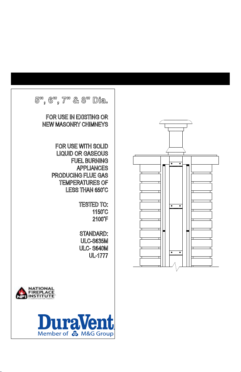
VENTINOX RIGID
FACTORY-BUILT LINING SYSTEM
INSTALLATION AND OPERATING INSTRUCTIONS
5", 6", 7" & 8" Dia.
FOR USE IN EXISTING OR
NEW MASONRY CHIMNEYS
FOR USE WITH SOLID
LIQUID OR GASEOUS
FUEL BURNING
APPLIANCES
PRODUCING FLUE GAS
TEMPERATURES OF
LESS THAN 650°C
TESTED TO:
1150°C
2100°F
STANDARD:
ULC-S635M
ULC- S640M
UL-1777
Printed in Canada REV1/JAN 2015 PIVENTINOX
Page 2
Installation and Operating Instructions
Read these instructions and keep them for future reference.
Before installing this liner, consult your local building
authority and obtain a building permit
Install the liner as described in these instructions. Only use parts supplied
by DURAVENT Ltd. Failure to do so will void the certication and the
guarantee of this chimney.
GENERAL NOTES
1. Ventinox Rigid lining system can be substituted to
the traditional clay tile liner in new masonry chimney
construction.
2. The liner is intended for use with solid, liquid and
gaseous fuel burning appliances at these allowable
ue gas temperatures :
U.S CANADA
Maximum continuous 1000 F
Brief forced ring 1400 F
Tested to 2100 F
540 C
760 C
1150 C
( 10 min)
TABLE 1
3. Size the liner in accordance with the appliance
manufacturer's instructions. The liner must not be
smaller than the appliance ue outlet.
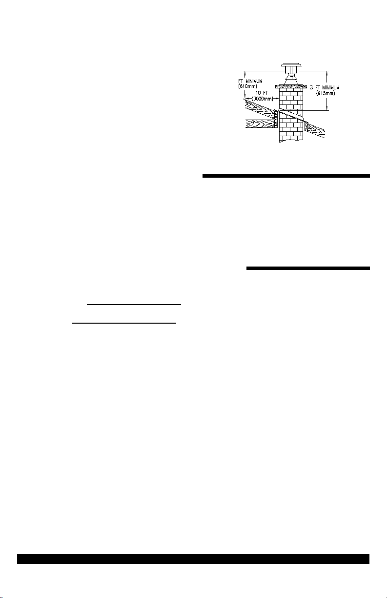
4. The chimney shall extend at least 3 ft (915 mm)
above its point of contact with the roof and at least
2 ft (10 mm) higher than any wall, roof or adjacent
building within 10 ft (3 m) of it (g. 1).
5. The clearance between single wall stove pipe and
unprotected combustible material must not be less
than 18" (457 mm) (See National Building Code or
NFPA).
6. A rain cap must be used on top of the liner to
prevent the entrance of debris, rain, birds or small
animals into the liner.
7. Homeowners must be reminded to check the rain
cap for icing during conditions of low ambient
temperatures due to the possibility of blockage
through freezing moisture. The local authority
having jurisdiction should be consulted if a rain cap
is considered in areas of low ambient temperature.
1200 F
650 C
1700 F
925 C
2100 F
1150 C
( 30 min)
8. Masonry chimney construction:
• The masonry chimney must be built with bricks
and mortar conformed to the Building Code.
The ue opening dimension must always leave
the liner free to expand.
9. The maximum height of liner that can be installed is
60 feet (18 m).
10. Special precaution should be taken in choosing the
correct size of liner system in colder climate region.
Poor draft, excessive condensation and creosote
build-up could occur if the liner system is too big for
the application.
11. Sharp bends that would crimp and restrict the crosssection of the liner are prohibited.
MASONRY CHIMNEY
Before installing the liner into an existing masonry
chimney, the chimney must be thoroughly cleaned
and examined. Check to ensure that the chimney is
structurally sound.
Check for cracked, loose or missing bricks, moisture
or other materials that could inhibit correct installation
of the liner.
Interior
installation
Exterior
installation
NFPA211 National
2``(50 mm) 2`` (50 mm)
1`` (25 mm) 1`` (25 mm)
TABLE 2
Building code
VENTINOX LINING SYSTEM - 2
Page 3
For a new masonry chimney liner installation make sure
that the masonry chimney construction and clearances
between the chimney exterior and combustible
materials are as specied in NFPA 211 (USA) or the
National Building Code (Canada) (See table 2).
Figure 1
YOU CAN DO IT ... STEP BY STEP !
Congratulations! You have made a wise choice in your selection of a VENTINOX lining system. You have purchased
a ne quality system researched, developed and tested to precise standards of quality in manufacturing.
It’s so easy to install…you can do it step by step. Each component is designed to t together perfectly and easily. If
you are handy with a few basic tools and have a general knowledge of carpentry, you can install your VENTINOX lining
system over a weekend or have a professional install it for you in a few hours.
Before you install your TUBINOX lining system, read these instructions carefully and follow them exactly.
DEAR CUSTOMER, INSTALLED, OR END USER
We welcome any comments regarding matters pertaining to our DURAVENT products.
We welcome any ideas, input or complaints and I`ill make sure thaht someone responds dirctly back to you.
Send your emails to: president@duravent.com
If you are searching for tech support or product information, please phone us at 800-835-4429.
Or email us at : techsupport@duravent.com
VENTINOX LINING SYSTEM - 3
Page 4
GENERAL INFORMATION
CREOSOTE
When wood is burned slowly, it produces tar and other organic vapours, which combine with expelled moisture to form
creosote. The creosote vapours condense in the relatively cool chimney ue of a slow burning re. As a result, creosote
residue accumulates on the ue lining. When ignited, this creosote makes an extremely hot re.
Creosote formation in a chimney cannot be eliminated, but it can be minimized by :
1. Keeping the temperature of the gases in the chimney above 300ºF.
2. Making small hot res rather than slow burning, smoldering res.
The chimney liner should be inspected periodically during the heating season to determine if a creosote build-up has occur.
If a signicant layer of creosote has accumulated ((1/8" (3 mm) or more)) it should be removed to reduce the risk of a
chimney re.
CHIMNEY OPERATION AND MAINTENANCE
Keep your chimney and liner clean.
Do not allow more than 1/8" build-up of creosote in your liner. Wood stoves can quickly create large deposits of creosote in
the liner. Some wood stoves can create enough creosote in two weeks to cause a chimney re.
When using a wood stove, we recommend that you :
1. Initially inspect the liner system weekly. From this you will learn how often it will be necessary to clean your
liner.
2. The liner should be inspected at least once every 2 months during the heating season to determine if a
creosote or soot build-up has occur. If creosote or soot has accumulated, it should be removed to reduce the
risk of a chimney re.
3. Have your liner cleaned by a qualied chimney sweep. If you want to clean your liner yourself, then use plastic, wood
or stainless steel brushes. Do not use a brush that will scratch the stainless steel interior of the liner.
4. Do not expect chemical chimney cleaners to keep your liner clean. Their use does not negate the necessity of
periodically inspecting and cleaning your liner.
COAL
Some coals contain large quantities of sulphur (up to 7%). When coal is burned, sulphur and coal ashes are deposited in
the liner. This deposit combines with moisture to form a highly corrosive acid (Sulphuric Acid). In order to protect your liner,
we recommend that you burn only low sulphur coals (less than 1% sulphur). Have your liner cleaned within 48 hours of
shutting down your stove at the end of the heating season. Be certain that all the soot is removed. Wipe the liner ue using
a strong solution of baking soda and water. This can be done by wrapping a rag around a chimney cleaning brush, dipping
it in the baking soda-water solution, then passing it through the liner three or four times.
CHIMNEY FIRES
If you are having a chimney re, follow these steps:
1. Close all heater doors and combustion air controls. For replaces, block the replace opening with a non-
combustible material (such as an asbestos or steel sheet).
2. Alert your family to the possible danger.
3. If you require assistance, alert your re department.
4. If possible, use a dry chemical re extinguisher, baking soda or sand to control the re. Do not use water, as it may
cause a dangerous steam explosion.
5. Watch for smouldering or re on combustibles next to the stove, stove pipe and chimney. Check outside to ensure
that sparks and hot embers coming out of the chimney are not igniting the roof.
6. Do not use the stove again until your chimney and stove pipe have been inspected by a qualied chimney sweep
or Fire Department inspector. The TUBINOX lining system has been designed to withstand the intense heat of a
chimney re. Nevertheless, chimney res are dangerous and should be avoided.
VENTINOX LINING SYSTEM - 4
Page 5

INSTALLATION GUIDELINES
DuraVent Liners venting gas or oil appliances do not require a minimum clearance or
insulation between the outside of the liner and inside of the masonry shell*. Leave enough
clearance for the liner to slide into place without difculty.
For Venting Solid Fuel Appliance, a minimum of ½` clearance is require between the outside
of the liner and inside of the masonry. To meet Zero Clearance to combustible, insulation must
be used. (See insulating liner section for instruction).
*Please note: While insulation is not required for every installation (refer to UL1777 or ULC-S635 for appropriate
listings or standards), the performance of the entire heating system is greatly enhanced when installing insulating materials.
The venting system acts and reacts in step with the heating unit`s operation. Insulation improves draft and minimizes
condensation, helping ue surfaces warm up more quickly to achieve a heater’s rated efciency. Insulation is particularly
important for exterior chimneys.
Read the sections outlining insulating procedures before beginning the installation.
INSTALLATION INSTRUCTIONS
• The chimney lining system can be installed in a masonry or concrete chimney that complies with the building code.
• In Canada, a new masonry or concrete chimney construction must comply with CAN/CSA A405: Design and
Construction of Masonry Chimneys and Fireplaces.
INSTALLATION
• NEW CHIMNEY LINING (g.4)
1. To install a liner into a new masonry chimney, we
suggest that you install the liner as the chimney is
being constructed.
2. Start the masonry chimney construction, making
sure that the dimension and manufacture of the
bricks and mortar conform to the Building Code.
If you choose to insulate the liner.
See insulating liner section (Page 8) to
size the masonry chimney.
Fig. 2
Fig. 3
3. To start the liner installation, attach the tee to the
rst length. Insert the liner with the male (smaller
connection) end down. Twist lock the part together
(g.2). Attach the tee cap to the base of the tee.
• NOTE: Each joint takes 1 1/2" (38 mm) overlap.
4. Place the tee and length assembly on the support
base, then add lengths along the chimney
construction until the liner protrudes about 10 in.
(254 mm) above the masonry chimney (g.3).
5. Install the top support on top of the masonry
chimney using lag bolts and/or cement (Fig. 5).
6. Slip the support collar over the liner until it rests on
the support.Tighten the bolt to fasten it to the liner.
(Fig. 5)
7. Twist lock the rain cap to the top of the liner.
VENTINOX LINING SYSTEM - 5
Fig. 4 - New masonry liner installation for interior chimney
Page 6

8. Installation of wall radiation shield through a
combustible wall.
• From inside, frame a hole14 1/2" x 14 1/2" (368
mm x 368 mm) in the wall where the vent will pass
through.
• Adjust the insulated wall radiation shield length to
t the wall thickness and lock the two parts together
with three (3) screws supplied.
CAUTION: Make sure the wall radiation shield is
always in contact with the masonry chimney.
• Slide the wall radiation shield over the length and x
it to the wall using four (4) screws supplied (g. 6).
Note: The void in the four corners between the wall
radiation shield and the wall frame can be lled with
berglass insulation.
EXISTING CHIMNEY RELINING (g.7) :
1. At the bottom of the masonry chimney, set up a brick
or other non-combustible support on which the liner
will rest.
Note: On an installation lower than 30 feet, you may
support the liner from the top support.
2. Attach the tee to the rst liner length. Insert the liner
with the male (smaller connection) end down. Twist
lock the parts together (g. 2 page 4).
3. You may remove the horizontal branch to facilitate
lowering the liner into the chimney, then attach it
when in place. If you keep it, make sure it is solidly
attached.
4. To lower the liner into the chimney, we suggest that
you tie a small hook to a long rope and grip the hook
on the tee. Make sure the rope is on the outside
of the liner, so you will be able to add lengths and
lower the assembly down the chimney (g. 10). Add
lengths until the liner protrudes about 10" above the
masonry chimney top.
5. Install the support plate on top of the masonry
chimney using lag bolts and /or cement.
6. Slip the support collar over the liner until it rests on
the support plate. Tighten the bolt to fasten it to the
liner.
Fig. 5
Fig. 6
If you choose to insulate the liner
See insulating liner section (Page8).
VENTINOX LINING SYSTEM - 6
Fig. 7 - Existing masonry relining installation
Page 7

Fig. 8 - Lining sustem for new replace installation
Fig. 10
7. Twist lock the rain cap to the top of the liner.
8. From inside the house, twist lock the masonry
adaptor to the tee. Now fasten the adaptor’s collar to
the masonry wall.
Be sure there is at least 18 inch clearance between
the single wall pipe and any combustible material.
INTERIOR SUPPORT
A liner installed in a replace chimney will require an
interior support at the top of the replace.
• NEW CHIMNEY LINING (g.8)
• Install the support plate on top of the replace
• Proceed with the erection of the liner along the
chimney construction as described before.
• EXISTING FIREPLACE (g.9)
• Install the liner as described previously
• (see "existing chimney lining"). With the liner
hanging in the replace, place the interior support in
position and mark its location on the liner.
• Remove the support and attach the support collar
around the liner slightly above your mark.
• Attach the support to the replace wall using four
bolts and lags.
• Continue connection to your stove.
Fig. 9 - Existing replace relining installation
VENTINOX LINING SYSTEM - 7
Page 8

INSULATING DURAVENT LINERS
General Guidelines:
Duravent Liners have been tested and are listed to
UL 1777 and ULC-S635 standard at zero clearance to
combustibles and for use with all fuels. When venting
wood red heaters or replaces, a minimum of one inch
TherMix® or at least 1/2" of ProFoil are needed to conform
to the UL1777 and ULC-S635, zero clearance listing.
All temperature tests were performed on chimneys
featuring a 4” nominal masonry shell and a Security Liner
with or without the specied insulation between the liner
and interior of the chimney (no clay tiles). The outside of
the chimney was surrounded with a wood enclosure at
zero clearance as specied by the standard.
METHOD #1: INSULATING WITH
THERMIX
TherMix® is poured into the chimney AFTER the liner is
installed. TherMix® is a pre-mixed insulation material and
only requires the addition of water at the job site. Review
TherMix® literature to determine the volume of TherMix®
needed to ll a specic chimney.
Empty a TherMix® bag into a mortar trough or
wheelbarrow. Add 7 to 9 gallons of water and mix with a
hoe. Proper consistency is achieved when the material
feels damp but is still granular. Little or no water should
appear between ngers when a handful of TherMix® is
squeezed. Correctly prepared TherMix® pours like “loose
ll” into the void between the liner and the chimney.
Complete instructions are on each TherMix® bag.
During the pouring process, distribute the insulation
evenly into the available space. Spacers may be used
every 5 ft. to center the liner. Vibrate the liner by rmly
tapping it. Continue to pour TherMix® until the chimney is
lled to the top and nish as described previously. Inspect
the liner at this time to ensure that no TherMix® has fallen
inside the venting system.
All heaters or replaces can be red up right after the
installation is complete. Keep ue gas temperatures below
700 degrees F for three weeks. This allows for TherMix® to
dry gradually. The operator is responsible for making sure
that the heater is not over red during this initial period.
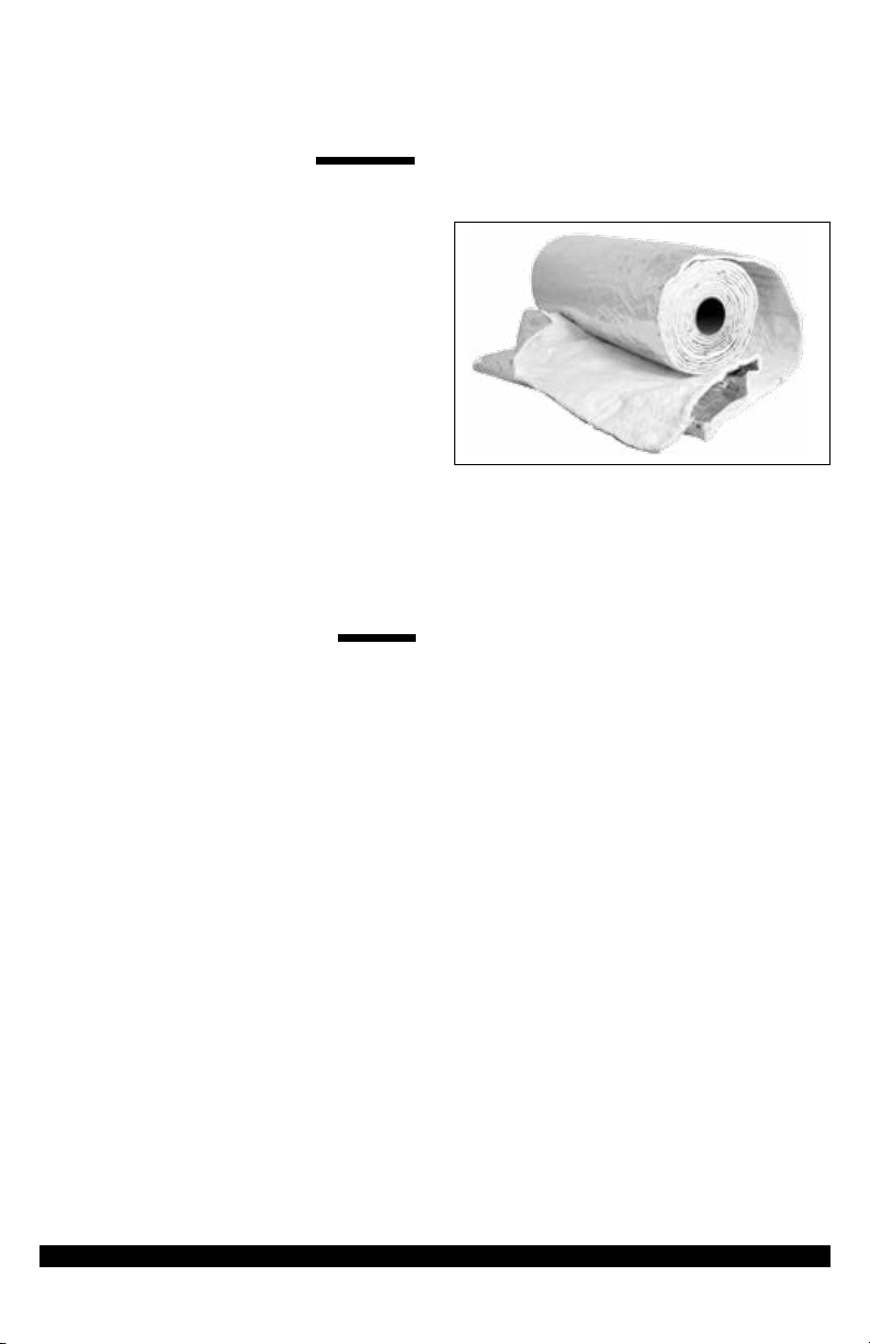
METHOD #2: INSULATING WITH
PROFOIL OR FLEXWRAP CERAMIC
BLANKETS.
Ceramic blankets are attached to DuraVent Liners as
the liner is installed into the chimney. Blankets are 1/2" in.
thick, 8 pounds density, and faced with a 2 mil. aluminum
®
Bag of TherMix
foil. The 1/2" thick blanket is the minimum amount of
insulation needed when using ProFoil. If using 1/4" ProFoil
blankets, two wraps are necessary to achieve the required
1/2" insulation. Aluminum tape, wire mesh and clamps are
needed for proper installation.
VENTINOX LINING SYSTEM - 8
Page 9
METHOD #1:THERMIX
BENEFITS AT-A-GLANCE:
• No Health Risks: Non-brous, non-toxic, inert and
manufactured under stringent quality controls. Safe
to the installer and homeowner, today and into the
future.
• Adds Safety: Chimneys insulated by TherMix reduce
creosote build-up, the chance of a chimney re is
minimized and its dangers are decreased.
• Superior Performance: Featuring high “R” values,
ue surface temperatures are balanced and react
quickly to ring cycles of heating units. Aiding in
optimal heating efciencies.
• Durable & Tested: When properly installed, TherMix
does not leak, separate or deteriorate. Field tested
since 1984.
• Reinforces: Insulates the liner & ue gas while
providing a strong bond for the masonry chimney.
THERMIX: THE “THERMAL
BRIDGE” BETWEEN
FLEXIBLE CHIMNEY
LINERS AND MASONRY
TherMix lowers temperatures on liners during over ring
or chimney res: Allows heat to be slowly absorbed into
the entire mass of a chimney, where it is safely dissipated
over a large surface area.
TherMix maintains higher temperatures on liners
when ue gas temperatures are low: Maintaining ue gas
temperatures above dew point, (~128°F), is essential
to avoid condensation. The insulating mass of TherMix
retains the maximum available heat close to the liner:
the ue stays warm for a longer period of time after the
appliance shuts down. With oil and gas appliances,
keeping the ue warmer between ring cycles greatly
reduces the possibility of momentary ue gas spillage
which occur at the start of the next cycle. With wood
burning applications, warmer ues help eliminate back
pufng and other draft related problems.
TherMix minimizes uctuations of liner surface
temperatures during heating cycles. This is critical when
draft must be established quickly each time an appliance
res up and when minimizing condensation within the
entire height of the ue is important.
NOTE: To comply with the specications
zero clearance solid ue installation, a
minimum thickness of 1” of TherMix must
be installed between a listed stainless steel
liner and a 4” thick masonry chimney wall.
ProFoil ceramic blanket
There is no change in consistency of TherMix over
time. Even after exposure to many high temperature
tests, the structural integrity, chemical composition, and
insulating qualities remained consistent over time, every
time.
• TherMix insulated chimneys can be used right after
the installation is complete, as long as ue gas
temperatures do not exceed 1000°F during the rst
48 hours of actual use. Please note that drying and
curing are two separate processes:
• Curing or hardening of TherMix takes place over
a 28-day period, with 65% to 75% of this process
occurring the rst week.
• Drying time depends on the thickness TherMix, the
permeability of the chimney, and weather conditions.
The drying process :
• Curing or hardening of TherMix takes place over
a 28-day period,with 65% to 75% of this process
occuring the rst week.
• Drying time depends on the thickness TherMix, the
permeability of the chimney, and weather conditions.
The drying process is enhanced and completed over
time by using the heating appliance.
VENTINOX LINING SYSTEM - 9
Page 10

TherMix Field Benets TherMix Ceramic Blankets
Zero-clearance to combustibles Yes Yes
Ease-of-installation Yes Yes
Diculties with Osets No Yes
Seals dangerous cracks and voids in chimneys Yes No
Eliminates air leakage into chimney Yes No
Eliminates moisture buildup between liner & chimney structure Yes No
Ships UPS/FedEx (Boxes Only) Yes Yes
Accepted by building code ocials Yes Yes
Can be removed Yes Yes
Avoids reliance on respirator during installation Yes No
Eliminates the need for reective surfaces to reduce heat transfer Yes No
Poured method means one size ts all insulation Yes No
Holds liner in place Yes No
Figure 2
WHEN USING THERMIX
There is no need to purchase spray adhesives, tapes,
wire, mesh, and/or sheet metal parts which add to the cost
and time to complete a job (Figure 2.)
• TherMix can be used to insulate modular masonry
replaces.
• TherMix stays in place when installed but can be
easily removed. Dry weight per cubic foot installed
is ~20lbs.
TherMix is delivered in a strong poly-lined bag or
box containing all ingredients except water, which must
be added to moisten the material (Figure 3.) Proper
consistency is achieved when the material feels damp but
still granular (~7 to 9 gallons of water per bag/box). *When
a handful of properly moistened TherMix is squeezed hard,
little to no water appears between the ngers.
During the installation, correctly prepared TherMix pours
like “loose ll.” TherMix is distributed within the chimney
cavity by vibrating the liner. *Do not tamp or compress
TherMix.
Figure 3
VENTINOX LINING SYSTEM - 10
Page 11
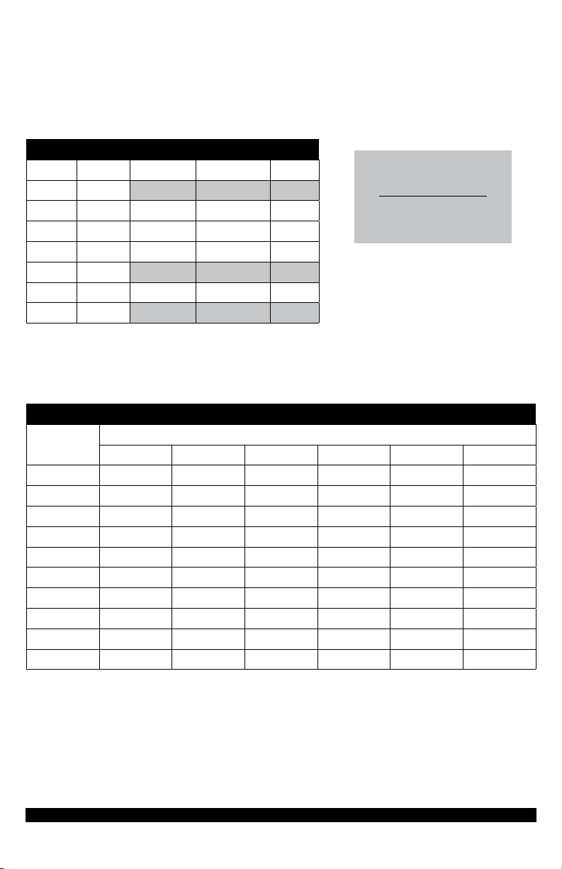
TABLE 2: CROSS SECTION AREA OF LINER
Liner Size CS Area Oval Liner Size Oval Dimensions CS Area
Round 5" 19.62in 2
Round 6" 28.46in2 Oval 6" (4.2" x 7.2") 24.60in2
Round 7" 38.46in2 Oval 7" (4.2" x 9.1") 32.20in2
Round 8" 50.25in2 Oval 8" (4.2 x 10.3") 37.20in2
Round 9" 62.50in2
Round 10" 78.50in2 Oval 10" (4.2" x 13.3") 49.5 0in2
Packages of TherMix
=
(W" x D" x H") - (CS x H")
1728 cu. in.
÷
3.25
W = Width of flue opening (in inches)
D = Depth of flue opening (in inches)
H = Height of flue (in inches)
CS = Cross Section areas (table 2)
Round 12" 113. 22i n2
TABLE 1: THERMIX VOLUME PER ONE FOOT OF CHIMNEY HEIGHT
Flue Opening
5" 6" 7" 8" 10" 12"
Diameter of Liner
7.5" x 7. 5" .25 .20 - - - - - - - -
7.5" x 11.5" .46 .40 (Ovalized) .38 (Ovalized) .32 - - - -
8.5" x 8.5" .36 .30 .23 - - - - - -
8.5" x 11.5" .54 .48 .41 (Ovalized) .36 (Ovalized) .33 - -
9.5" x 9.5" .49 .43 .36 .27 - - - -
11.5" x 11.5" .78 .72 .65 .60 .37 - -
11.5" x 16.5" 1.18 1.12 1.05 .96 .77 - -
12.5" x 12.5" .95 .88 .82 .73 .53 - -
14.5" x 14.5" 1.30 1.26 1.20 1.10 .92 .65
14.5" x 18.5" 1.70 1.66 1.60 1.50 1.30 1.04
VENTINOX LINING SYSTEM - 11
Page 12

METHOD #2 PROFOIL ATTACHING CERAMIC BLANKETS TO A
DURAVENT LINER:
Roll out the insulation blanket on a clean surface, foil
face down. Lay the liner on top and trim the blanket so that
it is about 1 1/2" shorter than the liner.
Wrap the insulation around the liner lengthwise and trim
it so that a butt joint is formed. Seal the joint with aluminum
foil tape. Spray adhesive may be used to hold the blanket
in place until it can be secured with the foil tape. A
minimum of 1/2" of insulation is required. If a double layer
of blanket is needed, install it with the butt joint on the
opposite side.
Install ProMesh protective wire mesh over the
blanket(s). The ProMesh is used to protect the ProFoil
insulation as the liner is lowered into the chimney. Slip the
ProMesh over the insulated liner and secure one end with
a stainless steel band clamp. Pull the ProMesh towards
the other end of the liner so that it tightens snugly around
the insulation, then trim off the excess. Secure this end
with a stainless steel band clamp.
1/2" of ProFoil
Attaching a ceramic blanket
VENTINOX LINING SYSTEM -12
 Loading...