

Page 1

Installation Instructions
PolyPro Double-Wall Flex
Gas Vent System for Category II &
IV Gas-Burning Appliances
PolyPro
®
Flex
Page 2
A MAJOR CAUSE OF VENT RELATED FIRES IS FAILURE
TO MAINTAIN REQUIRED CLEARANCES (AIR SPACES)
TO COMBUSTIBLE MATERIALS. IT IS OF THE UTMOST
IMPORTANCE THAT POLYPRO
® BE INSTALLED ONLY IN
ACCORDANCE WITH THESE INSTRUCTIONS.
• Assure unrestricted vent movement
IMPORTANT
Throughout this manual you will see
special attention boxes intended to
supplement the instructions and make
special notice of potential hazards.
In the judgement of M&G DuraVent,
these categories mean:
WARNING
Indicates a condition or hazard which
may cause severe personal injury, death
or major property damage.
CAUTION
Indicates a condition or hazard which
will or can cause minor personal injury
or property damage.
WARNING
Risk of carbon monoxide poisoning
or re due to joint separation or pipe
breakage.
• Examine all components for possible
shipping damage prior to installation;
• Read all instructions before beginning
the installation and follow these
instructions exactly as written.
• Proper joint assembly is essential for a
safe installation. Check the integrity of
ALL joints upon completion of assembly
• This venting system must be free to
expand and contract under normal
operation.
where required through walls, ceilings
and roof penetrations.
• This venting system must be supported
in accordance with these instructions.
• Do not mix pipe, ttings, or joining
methods from dierent vent system
manufacturers. Do not use adhesives of
any kind with this venting system.
Keep these instructions for future
reference.
Dear Customer, Installer, or End User:
We welcome any comments regarding
matters pertaining to our DuraVent products.
We welcome any ideas, input or complaints
to help improve our product oering. Send
your emails to:
president@duravent.com
If you are searching for tech support or
product information, please phone us at
800-835-4429.
Or email us at:
techsupport@duravent.com
PolyPro® is one of M&G DuraVent's
GreenVent® line of products.
2
Page 3

PolyPro Flex Gas Vent System
For the most up-to-date installation instructions, see www.duravent.com
CONTENTS
APPLICATION . . . . . . . . . . . . . . . . . . . . . . . . . . . . . . . . . . . . . . . . . . . . . . . . . . . . . . . 4
MINIMUM CLEARANCE TO COMBUSTIBLES . . . . . . . . . . . . . . . . . . . . . . . . . . . . . 4
GENERAL INSTRUCTION NOTES . . . . . . . . . . . . . . . . . . . . . . . . . . . . . . . . . . . . .. . . . 4
INSTALLATION OF FLEX GASKET . . . . . . . . . . . . . . . . . . . . . . . . . . . . . . . . . . . . . . . . 5
MASONRY / SHEET ROCK ENCLOSURE . . . . . . . . . . . . . . . . . . . . . . . . . . . . . . . . 6
B VENT / RELINE . . . . . . . . . . . . . . . . . . . . . . . . . . . . . . . . . . . . . . . . . . . . . . . . . . . . . 9
WARRANTY . . . . . . . . . . . . . . . . . . . . . . . . . . . . . . . . . . . . . . . . . . . . . . . . . . . . . . . . . .12
PolyPro
®
Flex
3
Page 4
APPLICATION / LISTING
For specic information on application,
equivalent length of ttings, listings, etc.,
please reference M&G Duravent's installation
instructions for rigid pipe (Document L273).
M&G Duravent's PolyPro vent pipe should not
be installed in areas where the temperature
could exceed 230 F / 110 C.
PERMITS
Check with your local Building Ocial, Fire
Ocial, or other authority having jurisdiction
regarding permits, restrictions, and
installation inspections in your area.
MINIMUM CLEARANCE TO
COMBUSTIBLES
Refer to Table A for minimum clearances
to combustible materials. Use the values
shown in this table unless the appliance
manufacturer species otherwise. If there
is a conict between the two, the greater
clearance shall apply. It is prohibited to place
any type of insulation around the venting
system within these clearances.
CAUTION
Installation applications and
terminations shown in these
instructions must be approved by
the manufacturer of the appliance to
which it is applied. Use only listed M&G
DuraVent terminations with PolyPro
Venting.
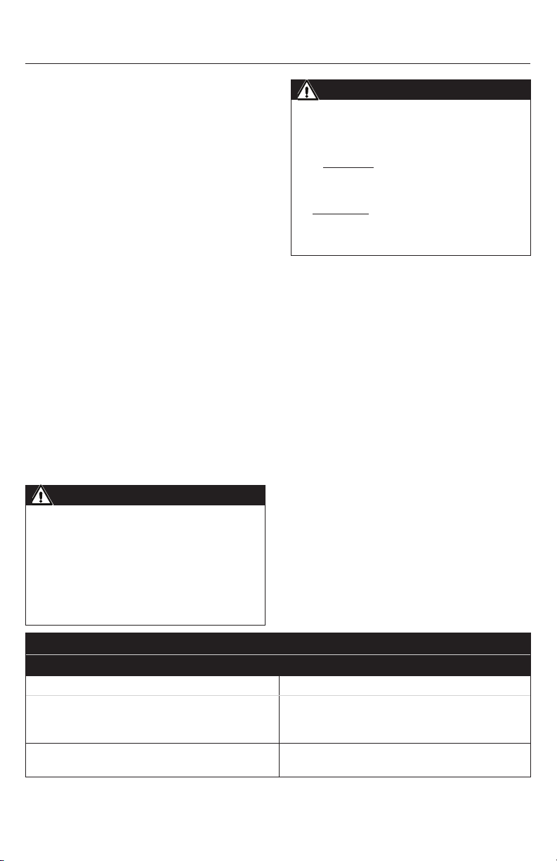
Table A
Minimum Clearance To Combustibles Table
VENT ORIENTATION
Horizontal Single Wall: 0" for ue temperatures up to 194*F (90*C).
Vertical Single Wall: 0"
IMPORTANT
The vent system must terminate in
accordance with local code requirements
and appropriate National Codes:
In the US: NFPA 54 / ANSI Z223.1
National Fuel Gas Code or the
International Fuel Gas Code.
In Canada: CAN/CGA-B149.1 Natural
Gas Installation Code or CAN/CGA-149.2
Propane Installation Code.
GENERAL INSTALLATION NOTES
Reference the Installation Instructions
provided with M&G Duravent's rigid pipe
(L273) for general instructions. PP Flex must
be enclosed, and used in conjunction with
rigid PP pipe to connect to an appliance.
• When used to conduct ue gases, PP ex
must not be installed at an angle greater
than 45 degrees from vertical. This will
ensure proper condensate ow back
towards the appliance outlet.
• PP Flex may be used to bring
combustion air into the appliance. In
these instances, pipe can be unenclosed
and oriented in a vertical or horizontal
position.
• PP ex must be treated carefully to
prevent damage when being installed
during low temperatures (<41°F, < 5 °C).
In colder weather, pre-warm ex prior
to installation. When relining, it may be
easier to insert ex from the bottom up
CLEARANCE
1/4" (6mm) for ue temperatures up to 230*F (110*C).
Flex: N/A- NOT ALLOWED
Flex: 0" (Must be enclosed)
4
Page 5

rather the top down.
• Always use soapy water to lubricate
gaskets prior to joint assembly. Do
not use Petroleum based lubricants!
• Plastic venting systems shall not pass
through rated re separations.
ADDITIONAL INSTRUCTIONS FOR
TERMINATION
M&G Duravent's PP Flex terminations are
specically designed for use with higheciency appliances that are known to
produce high volumes of uid due to
condensation of moisture within ue gases.
DO NOT modify these terminations.
IMPORTANT: Unless the appliance is designed
to address ow of condensates from the
vent system, a drain must be incorporated
within the vent to allow condensates and
rainwater to escape. This drain must include
a trap to prevent combustion gases from
entering living spaces. Be sure to check
the appliance manufacturer's installation
instructions closely in regards to condensate
management.
PP Flex pipe must always have gaskets
installed on both ends of any installation.
Gaskets are installed on the ex pipe, with the
gasket seating inside the ex pipe grooves
(Fig.1). Use soapy water to assist installation.
1. Cut PP ex pipe (knife, saw, etc) to
desired length. Special care should be taken
to ensure cut is square, and the edge is
deburred.
2. Place Flex Gasket over Flex pipe and install
in the rst whole groove nearest the end.
3. Open the locking tabs (x2) of the
appropriate ex tting to accept the ex pipe
(Fig.2)
4. Apply soapy water to the gasket, and push
pipe/gasket into appropriate ex tting,
seating pipe down until it bottoms out
(Fig.2).
Gasket in
fiRst
GRooVe
INSTALLATION OF FLEX GASKET:
PP flex PiPe
PP flex Gasket
flex aDaPteR
flex to coRRect
lenGth, clean eDGe
install Gasket, use
soaPy wateR
Figure 2, Installing Gasket / Flex Adapter
Figure 1, Mounting the Gasket
inseRt into
aDaPteR
lock PiPe to
aDaPteR
(click!)
5
Page 6

5. Close locking tabs on ex adapter so
tabs seat in the ex pipe. Slight adjustment
of pipe may be needed to ensure proper
engagement.
that is lined with a clay or concrete liner,
check to see if a short portion of the tile is
sticking out of the top of the chimney. If so,
this short top portion must be broken o to
permit the termination's ashing to sit down
ush on the chimney's crown. It is best to do
this prior to beginning the installation.
1. Determine the required location of the
opening within the enclosure. Ensure the ue
access cut-out meets the minimum specied
size to allow manual assembly of connections
within the ue. With masonry chimneys, the
breech opening may have to be enlarged
FLEX CHIMNEY LINING KIT
RoPe
Figure 3, Flex Puller
FLEX PULLER
A ex puller is an optional component
available to help ease installation of PP
Flex through enclosures (Fig.3). The
2"(60mm) version is of dierent design than
3"-5"(80mm-130mm).
2" Dia: Unscrew ceramic holder from cone.
Install ceramic holder around PP Flex pipe,
and re-install into cone.
3"-5" Dia: Connected using bayonet style
connection with a rotating movement of 1/4
turn to lock in.
MASONRY / SHEET ROCK
ENCLOSURE:
Examine the chimney or enclosure
carefully for obstructions prior to starting
an installation. Any structural defects or
potential safety problems must be repaired
prior to relining, and the enclsoure should be
clean. If working with a masonry chimney
1. Wall Plate
2. Support Elbow
3. Flex Chimney Support
4. Flex Male Adapter
5. Clamp (or Tie)
6. Flex Coupler
7. Gasket
8. Flex Liner
9. Spacer
10. Support Bracket
11. Flex
Female Adapter
12. Flex Chimney
Cap Flashing
13. Termination
Pipe
6
1
13
12
11
10
7
9
8
7
5
4
3
2
6
Page 7

to permit proper access. If this is the case,
patch up the opening after the installation
is completed using best practices. The slope
of the rigid connecting ue pipe must have a
minimum of 3° (equivalent 5cm/m) (5/8" per
foot).
2. Fix the Flex Chimney Support
(Fig.4) with 4 screws on the wall of the
enclosure.
6. Install PP Flex liner into the enclosure. A
second person is required to help feed the
exible liner into position (feeding either
from the top or bottom of the enclosure).
This will also help prevent damage from
occurring.
7. After installing the required length of liner,
remove the Flex Puller (if applicable)
8a. Position the Support Elbow on the Flex
Chimney Support (see 2 and 3, Fig.5)
8b. Secure the Support Elbow with the clamp
around the Flex Male Adapter and through
the slot of the Flex Chimney Support (see 1,
Fig.6).
1
2
1
3
Figure 4, Mounting Flex Chimney Support
3. The length of the exible liner can be
determined in two ways: use a rope with
a weight to measure the shaft length, add
16" (40cm) extra length for each bend. The
exible liner can be shortened with a saw or
scissors by cutting in a groove. The correct
length can also be determined after installing
the liner in the shaft and cutting it at the top
of the chimney, see Fig.8, dimension B.
4. Mount the Gasket into the ex pipe, and
attach to the appropriate coupler as detailed
above.
5. Mount the Spacers with a maximum
distance between them of 6 feet (2m).
Figure 5,
Installation
Support Elbow
Figure 6,
Securing
Support Elbow
9. Mount the Wall Plate on the wall of the
shaft (Fig.7). Pay attention to the correct
slope of 3°. The pipe of the Support Elbow
must be in the centre of the hole in the Wall
Plate.
10. The Support Elbow can be shortened if
required- For single wall, Dim A (Fig.7) must
have a minimum length of 1.6" (40mm).
11. At the top of the shaft, shorten the
exible liner to the required length and make
sure that dimension B in Fig.8 is between 1½
- 2½" (between 38 and 64 mm).
7
Page 8

15. Install the Termination Pipe(see 1 ,
Fig.10). Assemble the storm collar portion of
the Flex Chimney Flashing (see 2, Fig.10).
16. Connect the appliance to the exible vent
=
=
=
system with M&G DuraVent rigid PolyPro vent
system.
=
1
A
Figure 7, Mounting the Wall Plate
13. Fit the Support Bracket (see 1, Fig.8)
over the liner and let it rest on the wall of the
shaft. Mount the Gasket as detailed above
(see Fig.1). Push the Flex Female Adapter on
the liner and close the latching tabs. Allow
the assembly to rest on the Support Bracket.
14. Seal the edge of the chimney shaft with
water-resistant sealant (see 1, Fig.9) and push
the Flex Chimney Flashing (see 2, Fig.9) on
the shaft and x it with four masonry anchors
(see 3, Fig.9).
B
1
3
2
1
Figure 9, Installing Vent Cap
1
2
Figure 8, Required Liner Length
8
Figure 10, Installing Termination Pieces
Page 9

B VENT RELINE:
From within the room where the appliance is located, remove any existing horizontal or angled
sections of B Vent. PP Flex cannot be installed at an angle greater than 45 degrees from vertical.
The B Vent Adapter-Lower will t over the bottom of the existing B Vent's vertical stack at or
near the ceiling. Carefully inspect the B Vent to ensure integrity. Ensure any visible screws or
obstructions are removed. PP Rigid pipe must be used to complete install to the appliance-
Instructions- 2" (60mm) PP Flex in B Vent
1. Remove existing B Vent termination cap
2. Carefully feed ex down through B Vent so
approx 2' of ex extends beyond the bottom
of the B Vent (Flex puller or rope aid optional)
3. Cut to length the top of Flex pipe and
insert ex through B Vent Adapter- Upper, and
through the Termination Base.
4. Install the PP Flex Gasket and Flex Female
Adapter onto Flex pipe using instructions in
previous pages.
5. Lower the B Vent Adapter- Upper onto the
top of the existing B Vent and secure using
screws (x3) supplied with the hardware kit.
6. Attach the Termination Top to the
Termination Cap (clicks when engaged),
then insert the Flex Female Adapter into the
Termination Cap. Push the assembly onto the
Termination Base (clicks when engaged, see
Fig.12).
7. Push the completed assembly down onto
the B-Vent Adapter- Upper. When level, secure
with three screws provided.
8. At the bottom end, cut the PP Flex to
length 3" below the bottom of the vertical B
Vent still portruding from the ceiling.
9. Install the Flex Gasket
and Flex Male Adapter onto
the Flex pipe
10. Install B Vent Adapter-
Lower. (Flex Male Adapter
should protrude beyond
per Fig.13)
(click!)
11. Secure the B Vent
Adapter- Lower to the B
Vent using three screws
from the supplied
hardware.
Figure 12
Figure 11- (2" Flex / B Vent)
teRMination toP
teRMination caP
flex feMale aDaPteR
2" (60MM) flex Gasket
2" (60MM) flex
teRMination Base
MountinG haRDwaRe
B Vent aDaPteR- uPPeR
B Vent PiPe
2" (60MM) flex Gasket
flex Male aDaPteR
MountinG haRDwaRe
B Vent aDaPteR- loweR
9
Page 10

B Vent
aDaPteR-
loweR
flex Male
aDaPteR
B Vent PiPe
MountinG
haRDwaRe
flex
feMale
aDaPteR
B Vent
aDaPteR-
uPPeR
B Vent
PiPe
c suPPoRt
BRacket
Figure 13
Instructions- 3" (80mm) PP Flex in B Vent
1. Remove existing B Vent termination cap
2. Carefully feed ex down through B Vent so
approx 2' of ex extends beyond the bottom
of the B Vent (Flex puller or rope aid optional)
3. Cut to length the top of Flex pipe and
insert ex through B Vent Adapter- Upper
4. Install PP Flex Gasket and Flex Female
Adapter onto Flex pipe per instructions
detailed above
5. Lower B Vent Adapter- Upper to the top
of the B Vent and secure with screws (x3)
supplied
6. Install C Support Bracket as shown in Fig.14
and lower Flex Female Adapter into B Vent
Adapter- Upper
7. Attach Termination Top to Termination Cap
(clicks when engaged), insert 3" Rigid Pipe
into Termination Cap, and attach Termination
Insert into Termination Cap (clicks). Then
connect Termination Insert to Termination
Transition (click).
8. Line up inner pipe connections and push
termination assembly down onto B Vent
Adapter- Upper and secure with screws (x3)
provided
9. Cut Flex to length 3" below the bottom of
the B Vent
10. Install Flex Gasket and Flex Male Adapter
on Flex
11. Install B Vent Adapter- Lower. (Flex Male
Adapter should protrude beyond per Fig.13)
12. Secure B Vent Adapter- Lower to B Vent
with hardware provided
Figure 14
teRMination toP
teRMination caP
3" (80MM) RiGiD PiPe
teRMination inseRt
teRMination tRansition
c suPPoRt BRacket
B Vent aDaPteR- uPPeR
flex feMale aDaPteR
3" (80MM) flex Gasket
3" (80MM) flex
B Vent PiPe
3" (80MM) flex Gasket
flex Male aDaPteR
MountinG haRDwaRe
B Vent aDaPteR- loweR
Figure 15- (3" Flex / B Vent)
10
Page 11

11
Page 12

POLYPRO WARRANTY
M&G DuraVent, Inc. (“DuraVent”) provides this warranty for PolyPro® for ten years. Subject to the limitations set fort h below, DuraVent
warrants that its products will be free from defects in material or manufacturing, if properly installed, maintained and use d. DuraVent
product s are fully warranted if installe d only by a professional installer. This Warrant y is transferable from t he original homeowner to the
buyer of the home within the warranted ten years. This warranty does not cover normal wear and tear, smoke damage or damage caused
by chimney res, ac ts of God, or any product that was: (1) purchased other than from an authorized DuraVent dealer, retailer or distributor;
(2) modied or altered; (3) improperly serviced, inspec ted or cleaned; or (4) subject to negligence or any use not in accordance with the
installation ins tructions included with the product as deter mined by DuraVent.
Installation ins tructions are available online at w ww.duravent.com under Support/Literature and through our Cus tomer Service Department
800-835- 4429 or customerser vice@duravent.com.
DuraVent provides the following warranties for PolyPro: One Hundred Percent (100%) MSRP 10 years from the date of purchase.
All warranty obligations of DuraVent shall be limited to repair or replacement of the defective pro duct pursuant to the terms and conditions
applicable to each pro duct line. These remedies shall constitute DuraVent’s sole obligation and sole remedy under this warranty. This
warranty provides no cash surrender value. The terms and conditions of this warranty may not be modie d, altered or waived by any action,
inaction or representation, whether or al or in writing, except upon the ex press, written author ity of an executive ocer of DuraVent.
This product is intended for venting only category IV appliances burning Nat ural Gas, Propane and Oil. All other fuels are not covered under
this warranty.
LIMITATIONS ON POLYPRO INTERNET SALES: Not withstanding any other terms or conditions of this PolyPro Warrant y, DuraVent provides no
warranty f or PolyPro® if it is not installed by a qualied professional installer.
DuraVent must be notied and given the opportunity to inspect defective product prior to replacement under the terms of this limited
lifetime warranty. All warranty claims must be submitted with pro of of purchase. Labor and installation costs are not covered under this
warranty. To obtain warranty service contac t: DuraVent Warranty Ser vice, 877 Cotting Ct., Vacaville CA 9568 8, or call 800-835-4429.
WHERE LAWFUL, DURAVENT DISCLAIMS ALL OTHER WARRANTIES, INCLUDING BUT NOT LIMITED TO IMPLIED WARRANTIES OF
MERCHANTABILITY AND FIT NESS FOR A PARTICULAR PURPOSE. IN NO EVENT WILL DURAVENT BE LIABLE FOR INCIDENTAL, CONSEQUENTIAL,
PUNITIVE OR SPECIAL DAMAGES O R DIRECT OR INDIRECT LOSS OF ANY KIND, INCLUDING BUT N OT LIMITED TO PROPERTY DAMAGE AND
PERSONAL INJURY. DURAVENT’S ENTIRE LIABILITY IS LIMITED TO THE PURCHASE PRICE OF THIS PRODUCT. SOME STATES DO NOT ALLOW
LIMITATIONS ON IMPLIED WARRANTIES, OR THE EXCLUSION OR LIMITATION OF INCIDENTAL OR CONSEQUENTIAL DAMAGES, SO THE ABOVE
LIMITATIONS AND EXCLUSIONS MAY NOT APPLY TO YOU. THIS LIMITED WARRANTY GIVE S YOU SPECIFIC LEGAL RIGHTS, AND YOU MAY ALSO
HAVE OTHER RIGHTS THAT VARY FROM STATE TO STATE.
For the most up-to-date installation instructions, se e www. duravent.com
REV 3.22.2012
Customer Service Support 800-835-4429 707-446-4740 FAX www.duravent.com
PolyPro® and GreenVent® are registered trademarks of M&G DuraVent, Inc.
All rights reserved, ©2012 M&G DuraVent is a member of M&G Group.
9/2012 l272
 Loading...