

Page 1
Installation Instructions
PolyPro Single-Wall Gas Vent
System for Category II & IV
Gas-Burning Appliances
PolyPro
®
Page 2
A MAJOR CAUSE OF VENT RELATED FIRES IS FAILURE
TO MAINTAIN REQUIRED CLEARANCES (AIR SPACES) TO
COMBUSTIBLE MATERIALS. IT IS OF THE UTMOST IMPORTANCE
THAT POLYPRO® BE INSTALLED ONLY IN ACCORDANCE WITH
THESE INSTRUCTIONS.
WARNING
CARBON MONOXIDE POISONING
HAZARD. Failure to follow the steps
outlined below for each appliance
connected to the venting system being
placed into operation could result in
carbon monoxide poisoning or death.
• Examine all components for possible
shipping damage prior to installation;
• Read all instructions before beginning
the installation and follow these
instructions exactly as written.
• Proper joint assembly is essential for a
safe installation. Check the integrity of
ALL joints upon completion of assembly
• This venting system must be free to
expand and contract under normal
operation.
• Assure unrestricted vent movement
where required through walls, ceilings
and roof penetrations.
• This venting system must be supported
in accordance with these instructions.
• Do not mix pipe, ttings, or joining
methods from dierent vent system
manufacturers. Do not use adhesives
of any kind with this venting system.
insurance and safety listing of your
appliance. Acceptance of the installed
system is dependant on full compliance
with these installation instrucitons
WARNING
Risk of carbon monoxide poisoning
or re due to joint separation or pipe
breakage.
Keep these instructions for future
reference.
Dear Customer, Installer, or End User:
We welcome any comments regarding
matters pertaining to our DuraVent products.
We welcome any ideas, input or complaints
to help improve our product oering. Send
your emails to:
president@duravent.com
If you are searching for tech support or
product information, please phone us at
800-835-4429.
Or email us at:
techsupport@duravent.com
PolyPro® is one of M&G DuraVent's line of
products.
Page 3

PolyPro Single-Wall Gas Vent System
For the most up-to-date installation instructions, see www.duravent.com
CONTENTS
LISTING. . . . . . . . . . . . . . . . . . . . . . . . . . . . . . . . . . . . . . . . . . . .. . . . . . . . . . . . . . . . . 4
APPLICATION. . . . . . . . . . . . . . . . . . . . . . . . . . . . . . . . . . . . . . . . . . . .. . . . . . . . . . . 4
PERMITS . . . .. . . . .. . . . . . . . . . . . . . . . . . . . . . . . . . . . . . . . . . .. . . . . . . . . . . . . . . . . 4
GENERAL INSTALLATION NOTES. . . . . . . . . . . . . . . . . . . . . . . . . . . . . . . . . . . . . . 4
CLEARANCES TABLE 1. . . . . . . . . . . . . . . . . . . . . . . . . . . . . . . . . . . . . . .. . . . . . . . . . . 4
CONDENSATE DRAIN . . . . . . . . . . . . . . .. . . . . . . . . . . . . . . . . . . . . . . . . . . . .. . . . .4
JOINT CONNECTIONS. . . . . . . . . . . . . . . . . . . . . . . . . . . . . . . . . . . . . . .. . . . . . . . . .. . . . 5
EQUIVALENT LENGTH CHART TABLE 2 . . . . . . . . . . . . . . . . . . . .. . . . . . . . . .. . . . 5
APPLIANCE CONNECTION . . . . . . . . . . . . . . . . . . . . . . . . . . . . . . . .. . . . . . . . . . . 6
INSTALLATION . . . . . . . . . . . . . . . . . . . . . . . . . . . . . . . . . . . . . . . . . . . . . . . . . . . . . . 7
ENCLOSURE REQUIREMENTS . . . . . . . . . . . . . . . . . . . . . . . . . . . . . . . . . . . . . . . . 7
HORIZONTAL TERMINATIONS . . . . . . . . . . . . . . . . . . . . . . . . . . . . . . . . . . . . . . . 8
WALL AND CEILING PENETR ATION TABLE 3 . . . . . . . . . . . . . . . . . . . . . . . . . . . . 9
VERTICAL TERMINATIONS . . . . . . . . . . . . . . . . . . . . . . . . . . . . . . . . . . . . . . . . . . . 11
MULTIPLE VENT RUNS . . . . . . . . . . . . . . . . . . . . . . . . . . . . . . . . . . . . . . . . . . . . . . 12
ALUMINUM FLEX AIR INTAKE . . . . . . . . . . . . . . . . . . . . . . . . . . . . . . . . . . . . . . . . . . . 13
MAINTENANCE . . . . . . . . . . . . . . . . . . . . . . . . . . . . . . . . . . . . . . . . . . . . . . . . . . . . .13
WARRANTY. . . . . . . . . . . . . . . . . . . . . . . . . . . . . . . . . . . . . . . . . . . . . . . . . . . . . . . . . .14
PolyPro
®
3
Page 4
LISTING
Listed to ULC S636
Rated Class IIA, IIB, and IIC vent system
maximum temperature 230°F (110 °C)
maximum positive pressure 15 in-w.c.
Massachusetts Plumbers Board,
# G1-0811-42
APPLICATION
ANSI Category II and IV gas-burning
appliances
Appliances specically tested and listed to
use M&G DuraVent PolyPro Venting
PERMITS
Check with your local Building Ocial, Fire
Ocial, or other authority having jurisdiction
regarding permits, restrictions, and
installation inspections in your area.
GENERAL INSTALLATION NOTES
Read these instructions before beginning.
You must use only authorized M&G DuraVent
PolyPro vent parts, or other parts specically
authorized in these instructions and/or listed
by the appliance manufacturer in order to
maintain a safe, approved system.
• Do not ll any air space clearance
(Table 1) with insulation.
• Do not mix parts or try to match with
other products or use improvised
solutions.
• Do not install damaged or modied
parts.
Table 1
• Use soapy water to lubricate gaskets.
• Never use Petroleum base lubricants.
If these directions and those of the appliance
manufacturer dier, follow the more
conservative requirements. If you have any
questions, contact either your dealer or M&G
DuraVent directly. A venting system must
not be routed into, through, or within any
other vent, such as an existing masonry or
factory-built chimney ue, unless that vent
or chimney is not being used to vent another
appliance and is only used as a conduit for
the gas-vent system. Plastic venting systems
shall not pass through re rated separations
without approved restopping.
Refer to the appliance manufacturer's
instructions for maximum and minimum
vent lengths permitted with your specic
appliance model. This information should
include guidance on the maximum number
of elbows and related pressure-drops. The
total vent length from the appliance to
the termination shall not be greater than
specied by the appliance manufacturer.
If specic guidance is not oered by the
appliance manufacturer as to Equivalent
Vent Lengths (EVL) for vent components, the
general guidelines in Table 2 can be used.
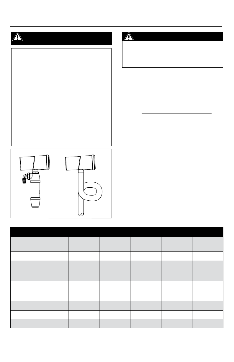
CONDENSATE DRAIN (Fig.1)
Refer to the appliance manufacturer’s
installation instructions for requirements of
condensate drainage. Ensure proper system
slope for drainage. (Fig.7)
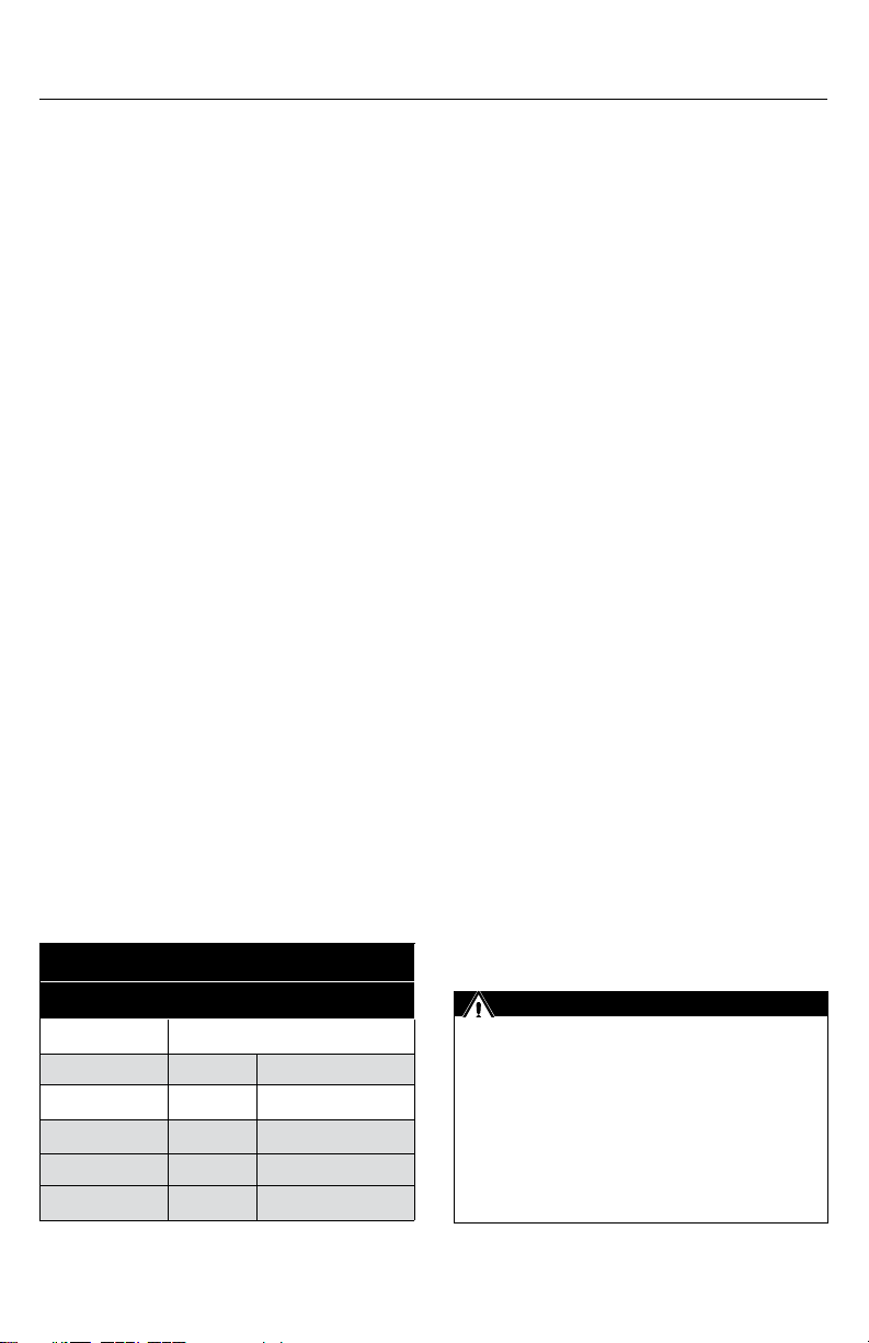
Clearance to Combustibles
VENT PIPE ORIENTATION
Single Wall Vertical Horizontal
Up to 190°F 0" 0"
Up to 230°F 0" ¼" (6mm) all around
Concentric
Up to 230°F 0" 0"
4
IMPORTANT
The vent system must be compliant in
accordance with local code requirements
and appropriate National Codes: In
the US: NFPA 54 / ANSI Z223.1 National
Fuel Gas Code or the International Fuel
Gas Code. In Canada: CAN/CGA-B149.1
Natural Gas Installation Code or CAN/CGA-
149.2 Propane Installation Code.
Page 5
IMPORTANT
To prevent possible recirculation of ue
gases, the installer must consider the
eects of prevailing wind conditions,
eddy zones, nearby buildings,
obstructions, or other obstacles such as
shrubs when planning exhaust and air
intake locations. M&G DuraVent can not
be held responsible for poor appliance
performance or damage to buildings
due to an incorrect installation. The
minimum clearances detailed within our
instructions may not be adequate in some
circumstances depending on the specics
of the installation. For this reason we
always recommend vertical venting.
SIPHON
P-TRAP
Figure 1
WARNING
CARBON MONOXIDE POISONING HAZARD
Failure to follow these installation
instructions could result in personal
injury or death
JOINT CONNECTIONS
Verify the gasket is seated evenly inside the
groove in the female end. There are two
versions of locking band available, one with
stando legs (Fig.2), one without (Fig.3).
For both: Slide Locking Band on male pipe
section. Fig.2: For pipe without Locking
Button: Slide pipe sections together until
joint is bottomed out then slide apart
¼”
to 5/8” (7.5 - 15 mm) for expansion. Clip the
locking band clasp onto the female hub.
Fig.3: For PP/Metal pipe with Locking Button:
Insert locking button into locking band
recess, rotate button away from Locking
Band Clasp, insert pipe sections, push
lock band clamp downward into socket,
disengage button 1/4" from socket. Screws
are not allowed for joint connection.
Never penetrate the wall of PolyPro vent
pipe. (Exception- a SS screw may be
used outside the building on exterior
termination ttings to orient an elbow,
etc).
• IMPORTANT: Locking bands are
Table 2 - Equivalent Length Chart
2" Equivalent
Length
1-ft Vent Pipe 1-ft 1-ft 1-ft 1-ft 1-ft 1-ft
2-ft
1-ft Flex Pipe
1-ft Flex Pipe
45 Elbow 3-ft 3-ft 5-ft 6-ft 6-ft 13-ft
90 Elbow 5-ft 7-ft 12-ft 14-ft 14-ft 19-ft
Tee 9-ft 12-ft 19-ft 21-ft 22-ft 29-ft
(same diameter
as rigid)
0.4-ft
(updsized one
diameter)
3" Equivalent
Length
2-ft
(same diameter
as rigid)
0.6-ft
(updsized one
diameter)
4" Equivalent
Length
2-ft
(same diameter
as rigid)
0.6-ft
(updsized one
diameter)
5" Equivalent
Length
2-ft
(same diameter
as rigid)
N/A N/A N/A
6" Equivalent
Length
N/A N/A
8" Equivalent
Length
5
Page 6

MALE
FEMALE
END
LOCKING
BUTTON
END
Figure 2
LOCKING
BAND RECESS
LOCKING
BAND CLASP
LOCKING BAND
PUSH DOWN
TO LOCK
VERIFY GASKET IS
SEATED IN FEMALE
END OF PIPE
PRY OUT
TO UNLOCK
CLICK!
APPLIANCE CONNECTION: 2" - 4"
1. If the appliance has a PVC/CPVC female
outlet use the Appliance Adapter/ PVC
Adapter and Clamp. (Fig.4)
• If the appliance has a PVC/CPVC
Male outlet use a matching PVC/
CPVC coupling to convert to a
female outlet.
2. If the appliance outlet has a rubber
boot or Fernco-style appliance adapter,
then the PolyPro vent pipe may attach
directly to the appliance (Fig.5).
3. If the appliance has a FasNSeal outlet
then use the FasNSeal to PolyPro
adapter.
1/4"
POLYPRO PIPE
APPLIANCE
ADAPTER CLAMP
APPLIANCE ADAPTER/
PVC ADAPTER
APPLIANCE
EXHAUST OUTLET
OR PVC UNION
Figure 3
mandatory on all exhaust vent joints
on pipe sizes from 2" up to 4". (Fig.2, 3)
• For 5"-8" diameter, Locking Bands are
not required but strongly recommended
at every exhaust vent joint.
(Fig.2, 3)
• Locking bands are optional for air inlet
vent joints.
POLYPRO TO DURAVENT / SECURITY
CHIMNEY METAL VENT CONNECTION
Approved M&G Duravent / Security Chimney
1738/636 metal vent ttings can be used with
PolyPro. For PolyPro (female) to Metal Vent
(Male) connections, the metal ttings will have
a Locking Button or Protrusion, and will be
connected simliar to Fig. 3.
6
(Fig.2, 3)
APPLIANCE
Figure 4
Figure 5
POLYPRO
VENT PIPE
TIGHTEN CLAMPS ON
RUBBER COUPLER
ADAPTER OR FERNCO
STYLE ADAPTER TO
SECURE VENT
PIPE TO APPLIANCE
APPLIANCE
OUTLET
Page 7

INSTALLATION
1. Pipe lengths may be cut to length
(Fig.6). Use an alternate clamp (Fig.4PPS-PAC / PPS-LBC) for the connection
if a locking button (Fig.3) is removed.
• Cut square (not at an angle) to the
end of the pipe.
• Remove burrs before assembly.
MARK
CUT WITH
HACKSAW
TO APPLIANCE
5/8"
1/4" 5/8"
7.5mm 15mm
MIN
12"
Figure 7
IMPORTANT
PP Pipe sections must be disengaged 1/4"5/8" per joint (to allow for expansion) and
sloped 3°(5/8"per ft) back to the appliance
per Fig.7 for proper condensate flow.
DEBURR
Figure 6
2. Check with appliance manufacturer for
any restrictions or limits on vent length,
number of elbows, etc.
3. The slope of the vent pipe must be at
least 3° (5/8" per ft, 50mm per meter)
back to the appliance. (Fig.7)
4. Every horizontal section must be
supported. (Fig.8)
5. The venting system shall be securely
supported using suitable hangers.
Duravent hardware is recommended; eld
supplied support hardware suitable to
the AHJ is acceptable, hardware must not
deform or damage the vent. (Fig. 7 and 8)
Make sure the load of the vent system is not
supported by the appliance.
• On Duravent and other certain clamp
styles, ¼” or greater All-thread may be
used as an extension.
6. Vertical installations must be supported
every 10 feet (3 meters) or less. (Fig.8)
7. Do not install / enclose PolyPro in the stud
space of a wall.
8. Elbows and Tees are suciently supported
when a bracket is xed at the female end of
the connected straight section. (Fig.8)
ALLTHREAD
LOCKING BANDS
REQUIRED AT EVERY
EXHAUST JOINT
MAX
10FT
3m
WALL STRAP
MINIMUM 1PER
HORIZONTAL PIPE
SECTION
Figure 8
9. Vertical components can be insulated in
unconditioned space or when ran outside.
10. Use black UV protected components on
venting installed on the exterior.
ENCLOSURE REQUIREMENTS
Through Rooms: Interior vents shall be
enclosed where they extend through closets,
storage areas, occupied spaces, or anyplace
where the surface of the vent could be
contacted by persons or combustible materials
except when installed in the room with the
appliance.
7
Page 8

Multi-Story: Consult local building or other
applicable codes for requirements in your
area. In the U.S., NFPA 211 10.6.3 (2013)
states: “Vents that pass through the oors
of buildings requiring the protection of
vertical openings shall be enclosed within an
approved enclosure. The enclosure walls shall
have a re resistance rating of not less than
1 hour where a vent is located in a building
less than four stories in height. The enclosure
walls shall have a re resistance rating of not
less than 2 hours where a vent is located in a
building four or more stories in height."
If the vent system is not exposed to wind or
lateral load within the enclosure and joints
cannot buckle, wall straps are not required
provided upper and lower supports are
proper.
ENCLOSURE
FIRESTOP
FIRESTOP
FIRESTOPS (Fig. 9)
1. Firestops are required at each ceiling/
oor penetration including an attic.
Firestops are not required at the roof
deck penetration.
2. Cut and/or frame hole. (Table 3)
3. Slide the two halves together and attach
to the ceiling.
INTERIOR
WALL PLATE
ALIGN TABS WITH
MOUNTS
EXTERIOR
WALL PLATE
GASKET
Figure 10
TERMINATIONS:
Horizontal Single Pipe (Fig.10)
1. Locate penetration in wall.
2. Cut or cut and frame hole. (Table 3)
3. Attach Inner Plate to wall.
4. Attach / seal Outer Plate to outside wall.
5. Line up keyway, slide black pipe (UV
Protected) or termination through
plates.
6. If termination is used, attach with
screws. Align tabs with pipe mounts.
REMOVE GASKET
FIRESTOP
INSERT BIRD GUARD
Figure 9
Figure 11
8
Page 9

Table 3 - Wall & Ceiling Penetration Sizing Table
VENT DIAMETER
Termination 2" 3" 4" 5" 6" 8"
CONCENTRIC
VERTICAL OR HORIZONTAL
TWIN PIPE HORIZONTAL
CLASS IIB
TWIN PIPE HORIZONTAL
CLASS IIC (Framing Dimensions)
4 ⁄"
105mm
7 ⁄" x 2⁄"
187mm x
65mm
8" x 3"
200 x 77mm
5 ⁄"
130mm
8 ⁄" x 3⁄"
212 x 85mm
8 ⁄" x 3⁄"
225 x 98mm
6 ⁄"
155mm
9" x 4⁄"
228 x 100mm
9 ⁄" x 4 ⁄"
238 x 112mm
N/A N/A N/A
N/A N/A N/A
N/A N/A N/A
SINGLE HORIZONTAL
CLASS IIB
SINGLE HORIZONTAL
CLASS IIC (Framing Dimensions)
SINGLE WALL W/ LOCKING BAND
VERTICAL
SINGLE PIPE NO LOCKING BANDS
VERTICAL
2⁄"
65mm /
3"
77mm
3 ⁄" "
85mm
3 ⁄
98mm
3 ⁄" 4 ⁄" 5 ⁄" 6 ⁄" 7 ⁄" 9 ⁄"
3" 3 ⁄" 4 ⁄" 5 ⁄" 6 ⁄" 7 ⁄"
7. Add additional components to raise vent
level if desired (vent to be 12" above
grade or average snow level).
8. Remove gasket and install Bird Guard
into end of pipe. (Fig.11)
9. Install Poly Pro venting system to/from
termination to appliance.
POSITIONED
HORIZONTALLY
INTERIOR
WALL PLATE
EXTERIOR WALL PLATE
EXHAUST PIPE
APPLY BEAD OF SILICON SEALANT
AROUND FEMALE END OF PIPE TO
SEAL AGAINST EXTERIOR WALL PLATE
EXHAUST TIP
4" "
100mm
4 ⁄
112mm
N/A N/A N/A
N/A N/A N/A
Horizontal Twin Pipe (Fig.12)
1. Locate penetration.
2. Cut or cut and frame hole. (Table 3)
3. Attach interior wall plate to inside wall.
4. Attach and seal exterior wall plate to
outside wall.
5. Slide pipes through outer plate.
6. Rotate pipes to slide pipe past keyway.
POSITIONED
VERTICALLY
AIR INLET PIPE
OUTER COVER PLATE
Figure 12
9
Page 10

7. Slide exhaust tip into exhaust pipe.
8. Mount outer cover plate to exterior wall
plate.
9. install Poly Pro venting system to/from
termination to appliance.
Horizontal Concentric (Fig.13)
1. Locate penetration.
2. Cut hole. (Table 3)
3. Attach and seal exterior exterior wall
plate onto outside wall.
4. Slide cap through exterior wall plate into
hole from outside building. Cap must
not be installed sloped downward.
5. Orient termination so air intake slots
face down.
6. Seal termination to exterior wall plate
with silicone sealant.
7. Slide interior wall plate over termination
and attach to wall from inside the room.
8. Attach interior wall plate to termination
with provided hardware.
9. Install gaskets into Co-Linear Adapter.
10. Attach Co-Linear Adapter to Horizontal
Termination.
11. Install Poly Pro venting system to/from
termination to appliance.
INSTALL
GASKETS
INTERIOR
WALL PLATE
EXTERIOR
WALL PLATE
POLYPRO PIPE
W/PVC ADAPTER
SUPPLIED WITH
TERMINATION KIT
BRACKET
Figure 14
Lochinvar 2" installation (Fig.14)
1. Slide PolyPro pipe w/ PVC adapter into
oblong hole and down. Brackets will
point away from the wall, on the exterior
of the house, and rest between the two
outward beads.
2. Install the termination assembly
in accordance with appliance
manufacturer’s instructions.
3. Verify exhaust pipe cannot be removed
from termination cap.
POLYPRO PIPE
W/PVC ADAPTER
SUPPLIED WITH
TERMINATION KIT
COLINEAR
EXHAUST
AIR INTAKE
10
ADAPTER
SCREW TO
TERMINATION
Figure 13
HORIZONTAL
TERMINATION
Figure 15
Lochinvar 3" & 4" installation (Fig.15)
1. Slide PolyPro Pipe w/ PVC adapter into
small hole of retaining plate until it stops
on the adapter collar.
2. Finish installing the termination
assembly in accordance with appliance
manufacturer’s instructions. PolyPro
Page 11

pipe is to be installed on the exhaust
outlet.
3. Once securely installed to exterior, verify
exhaust pipe cannot be removed from
termination cap.
Stainless Horizontal (Fig.16)
1. Cut opening in the wall.
2. Add Trim Plates and locking band (if
applicable) to nal pipe length before
installing. Make sure anges are facing
towards the wall. Use non-hardening
sealant where necessary.
3. After exterior trim plate is mounted to
wall, measure 3" from exterior plate and
cut o female pipe end. Duburr. Seal
pipe to exterior plate. Slide Bird screen
over cut pipe end and tighten clamp.
THROUGH HOLE SIZING
4PPS: 4.125" 5PPS: 5.25"
6PPS: 6.125" 8PPS: 8.00"
EXTERIOR PLATE
FLANGES
CUT LINE
INTERIOR PLATE
INITIAL
TERMINATION
CAP
STORM COLLAR
FLASHING
SUPPORT CLAMP
Figure 18
EXHAUST
AIR INLET
BIRD
SCREEN
CLAMP
Figure 16
Figure 17
PP PIPE
CENTERLINE OF
EXHAUST OUTLET
OF APPLIANCE
FINAL
Figure 19
Vertical Concentric (Fig.18)
1. Locate penetration. (Fig.17)
2. Cut hole in roof. (Table 3)
3. Cut hole in ceiling above appliance.
• Cut hole(s) big enough for pipe in all
ceilings above appliance if installing
in a multi story installation.
4. Firestop each ceiling penetration.
5. Attach ashing to roof. (Fig.18)
• Slide storm collar onto ashing if
using the Adjustable Roof Flashing.
6. Slide vertical termination into ashing
from above until seated on ashing.
7. Plumb Termination and mount support
bracket to structure.
11
Page 12

8. Install gaskets into Co-Linear Adapter (if
applicable). (Fig.13)
9. Connect Co-Linear Adapter to
termination (if applicable). (Fig.19)
10. Install Poly Pro venting system to/from
Co-Linear Adapter or termination to
appliance.
BIRD GUARD
BLACK
UV PROTECTED PIPE
max length rectangle, 4 vent runs max per
support. The listing requires clearance holes
no larger than 5 1/8" Dia, with spacing 1 3/4"
apart.
The upper support plate (with a ange for
B vent and factory built chimney, Fig.22)
must be axed to the top of the conduit via
screws. Anchor bolts must be used when
attaching a at support plate to the top of
Masonry or other chase (not shown). Support
plate must be weather tight. The SS Hanger
Bracket is installed under the Gasket Plate
and axed to the top of the support plate
with screws (Fig.22). Use non-hardening
sealant as required.
RUBBER FLASHING
Figure 20- Vertical Pipe Termination
Vertical single pipe (Fig.20)
1. Follow instructions for Vertical Concentric
Termination.
2. Attach ashing to roof. (Fig.20)
• Rubber boot ashing or similar,
ensure an eective, leak-proof seal
is maintained.
• Use BLACK UV protected pipe.
3. Maintain 12 in. (305mm) min. clearance
above highest anticipated snow level,
max 24 in. (610mm) above roof.
MULTIPLE VENTS IN ONE CONDUIT Fig.21
Multiple PolyPro Rigid/Flex vent systems may
be installed within one conduit. Listed 2"-4"
M&G components must be used, and the
conduit (if pre-existing) must be inspected
and deemed sound.
Upper supports may be eld supplied and
listed, the listing requires: Min thickness of 24
ga (0.020") SS, no larger than 18" Dia or 18"
The lower portion of the vent system must
be supported and restopped as detailed
earlier in these and/or the PP Flex instructions
(provided separately).
GASKET PLATE
/ HANGER
MOUNT
HARDWARE
GASKET
PLATE
1.75" MAT'L
SPACE MIN
CLEARANCE
HOLE
STAINLESS
RELINE
HANGER
BRACKET
POLYPRO
FLEX LINER
RIGID BLACK
UV PROTECTED
POLYPRO
STAINLESS
UPPER
SUPPORT
PLATE
FLANGE
RIGID
POLYPRO
Figure 21
12
Page 13

Figure 22
HANGER
MOUNTED
TO TOP OF
SUPPORT,
BELOW
GASKET
PLATE
SEAL AS
REQ'D
M&G DURAVENT
POLYPRO
CHIMNEY CAP
TERMINATION
COMBUSTION
AIR INTAKE
FLEX HANGER
BRACKET AND
HARDWARE
FLEX CLAMP
STORM COLLAR
M&G DURAVENT
POLYPRO
EXHAUST SYSTEM
ALUM FLEX AIR INTAKE (Fig.23)
Important: This section only applies to
sourcing combustion air!
Reference Fig.23 for installation of air intake
ex when used with the M&G DuraVent
Chimney Cap Termination. Combustion air
is drawn in under the storm collar. Ensure
Aluminum ex is approx 1"-2" below
termination base for unrestricted operation.
See Fig.24 for the lower install.
MAINTENANCE
Have your venting system checked annually.
This can be done easily by the same
technician who inspects & services the
appliance. Recommended areas to inspect
are as follows:
- Check areas of the Venting System which
are exposed to the elements for wear or
damage. If damage is found, the components
should be replaced immediately.
- Where possible, look into the Termination
Cap to verify no foreign material is there to
block the vent. Remove any foreign material
found.
- Where practical, inspect joints to verify
that no Pipe Sections or Fittings have been
disturbed, and consequently loosened. Also
check mechanical supports such as Wall
Straps, support plates, etc for rigidity.
AIR INTAKE
AIR INTAKE
FLEX
AIR INTAKE
FLEX TO
POLYPRO
ADAPTER
FLEX
Figure 23- Upper Assy
Figure 24- Lower Assy
ENCLOSURE
M&G DURAVENT
POLYPRO
EXHAUST SYSTEM
POLYPRO PIPE TO
APPLIANCE AIR
INTAKE
13
Page 14

THIS PAGE INTENTIONALLY LEFT BLANK
Page 15

THIS PAGE INTENTIONALLY LEFT BLANK
Page 16

POLYPRO WARRANTY
M&G DuraVent, Inc. (“ DuraVent”) provides t his warranty for Po lyPro® for ten years. Subj ect to the limitati ons set forth b elow, DuraVent warrants that it s
produc ts will be free fr om defects in m aterial or manufac turing, if proper ly installed, mainta ined and used. DuraVent pro ducts are fully wa rranted if install ed
only by a profe ssional installer. This War ranty is transf erable from the or iginal homeowner to t he buyer of the home wit hin the warranted ten ye ars. This
warrant y does not cover norma l wear and tear, smoke damage or damage c aused by chimney re s, acts of God, or any pr oduct that was: (1) purchase d
other than f rom an authorized D uraVent dealer, retailer or distr ibutor; (2) modied or a ltered; (3) improperly ser viced, inspec ted or cleaned; or (4) subjec t to
negligence o r any use not in accordance wit h the installation in structions i ncluded with the pr oduct as determin ed by DuraVent.
Installation instruc tions are available online at www.duravent.com under Support /Literature and th rough our Customer Se rvice Depart ment
800 -835-4429
or customerservice@duravent.com.
DuraVent provide s the following warr anties for PolyPro: On e Hundred Percent (100%) MSRP 10 years f rom the date of purchase .
All warrant y obligations of Dur aVent shall be limi ted to repair or replaceme nt of the defecti ve product pursu ant to the terms and condi tions applicable to
each produc t line. These reme dies shall constitu te DuraVent’s sole obligatio n and sole remedy under t his warranty. This war ranty provides n o cash surrender
value. The ter ms and conditions of th is warranty may not be m odied, altered or w aived by any action, ina ction or represe ntation, whether or al or in
writing , except upon the exp ress, written au thority of an exe cutive ocer of DuraVent.
This produc t is intended for ven ting only categor y II & IV appliances burni ng Natural Gas, Propan e and Oil. All other fuels ar e not covered under this
warranty.
LIMITATIONS ON POLYPRO INTE RNET SALES: Notw ithstanding any ot her terms or conditio ns of this PolyPro Warrant y, DuraVent provides no warra nty for
PolyPro® if it is n ot installed by a qualie d professional ins taller.
DuraVent must be no tied and given the op portunity t o inspect defe ctive produc t prior to replacement und er the terms of this limit ed lifetime warra nty.
All warrant y claims must be subm itted with proo f of purchase. Labor an d installation cost s are not covered under t his warranty. To obtain warr anty service
contact : DuraVent Warranty Ser vice, 877 Cotting Ct., Vaca ville CA 95688, or call 8 00-835-442 9.
WHERE LAWFUL , DURAVENT DISCLAIMS AL L OTHER WARRANTIES, INCLUD ING BUT NOT LIMITED TO IMPLIED WARR ANTIES OF MERCHAN TABILIT Y AND
FITNESS F OR A PARTICULAR PURPOSE. IN N O EVENT WILL DURAVENT BE L IABLE FOR INCIDENTAL, CONSE QUENTIAL, PUNITIVE O R SPECIAL DAMAGES OR
DIRECT OR I NDIRECT LOSS OF ANY KIND, INCLU DING BUT NOT LIMITED TO PROPE RTY DAMAGE AND PERSONAL I NJURY. DURAVENT’S ENTIRE LIABIL ITY
IS LIMITED TO THE P URCHASE PRICE OF THIS PRO DUCT. SOME STATES DO NOT ALLOW LIMITATIONS ON IMPLIE D WARRANT IES, OR THE EXCLUSION OR
LIMITATION OF INCIDEN TAL OR CONSEQUE NTIAL DAMAGES, SO THE ABOVE L IMITATIONS AND E XCLUSIONS MAY NOT APPLY TO YOU. THIS LIMIT ED
WARRANTY GI VES YOU SPECIFIC LEGAL RI GHTS, AND YOU MAY ALSO HAVE OTHER RIGHTS THAT VARY FROM STATE TO STATE.
For the mos t up-to-date ins tallation instr uctions, see www. duravent.com
REV 9.4.2012
Customer Service Support 800-835-4429 707-446-4740 FAX www.duravent.com
PolyPro® is a registered trademark of M&G DuraVent, Inc.
All rights reserved, ©2014 M&G DuraVent is a member of M&G Group.
820003161- L273 08/2014
 Loading...