

Page 1
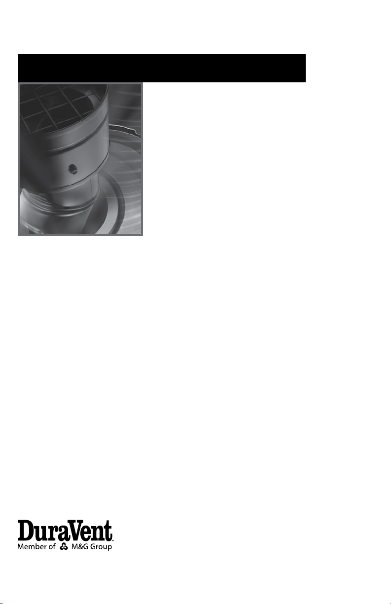
Installation Instructions
Venting System for Pellet, Corn, Oil,
and Biofuel appliances.
PelletVent Pro
Page 2

A MAJOR CAUSE OF VENT RELATED FIRES IS FAILURE
TO MAINTAIN REQUIRED CLEARANCES (AIR SPACES) TO
COMBUSTIBLE MATERIALS. IT IS OF THE UTMOST IMPORTANCE
THAT DOUBLE WALL PELLETVENT PRO BE INSTALLED ONLY IN
ACCORDANCE WITH THESE INSTRUCTIONS.
NOTE:
Read through all of these instructions before
beginning your installation. Failure to install
as described in this instruction will void the
manufacturer’s warranty, and may have an
effect on your homeowner’s insurance and
UL listing status. Keep these instructions for
future reference. This booklet also contains
instructions for installing a venting system
within an existing masonry chimney, and
for installations passing through a cathedral
ceiling.
Dear Customer, Installer, or End User:
We welcome any comments regarding matters
pertaining to our DuraVent products.
We welcome any ideas, input or complaints
and I’ll make sure that someone responds
directly back to you.
Send your emails to:
president@duravent.com
If you are searching for tech support or product
information, please phone us at 800-835-4429.
Or email us at:
techsupport@duravent.com
LISTED
MH8381
MH14420
Page 3

VENTING SYSTEM FOR PELLET, CORN, OIL, AND BIOFUEL APPLIANCES.
For the most up-to-date installation instructions, see www.duravent.com
CONTENTS
Clearances, Vent Listing, Installation Notes, Lubricants & Gaskets . . . . 4
Sealants, Fuel Selection, Best Practices . . . . . . . . . . . . . . . . . . . . . . . . . . . 5
Tools Needed, Permits, General Installation Instructions . . . . . . . . . . . . . . .6
Installation into Masonry Fireplaces . . . . . . . . . . . . . . . . . . . . . . . . . . . . . . 15
Installation Through Side of Masonry Chimney . . . . . . . . . . . . . . . . . . . . . .17
Installation in a Cathedral Ceiling . . . . . . . . . . . . . . . . . . . . . . . . . . . . . . . . . 18
Cleaning and Maintenance .. . . . . . . . . . . . . . . . . . . . . . . . . . . . . . . . . . . . . 21
PelletVent Pro
3
Page 4

CLEARANCES AND APPLICATIONS
Dura-Vent’s PelletVent Pro is listed by
Underwriters Laboratories as vent for listed
appliances that burn oil, pellet, corn, and other
biofuels. PelletVent Pro is also listed as a
masonry reliner with the minimum clearance
is 0” from vent to masonry, and 0” clearance
from the masonry to nearby combustibles.
Never ll any required clearance space with
insulation or any other materials. Combustible
materials include (but are not limited to)
lumber, plywood, sheetrock, plaster and
lath, furniture, curtains, electrical wiring, and
building insulation of any kind.
In the United States and Canada the minimum
clearance to combustibles from PelletVent
Pro is 1” for oil, pellet, corn or other biofuel
applications.
VENT LISTING
PelletVent Pro is listed by Underwriters
Laboratories (listing numbers MH8381 &
MH14420) to the American standard UL 641
Type L Low Temperature Venting Systems,
and is also listed to the Canadian standards
ULC S609 Standard for Low Temperature
Vents Type L and ULC/ORD-C441 Standard
for Pellet Vents .
INSTALLATION NOTES
Proper planning for your PelletVent Pro
installation will result in greater safety,
efciency, and convenience, saving both time
and money. Use only authorized Dura-Vent
PelletVent, CornVent, and PelletVent Pro
biofuel listed parts. Do not install damaged
parts.
1. WARNING: When passing through ceilings
and walls, make sure all combustible materials
and building insulation products are a
minimum of 1” from the vent pipe
2. For horizontal terminations, make sure
NFPA 211 rules are followed for minimum
distance from windows and openings.
3. Do not mix and match with other
manufacturer’s products or improvised
solutions.
4. Practice good workmanship. Sloppy
work could jeopardize your PelletVent Pro
installation.
5. Never use a vent with an inside diameter
that is smaller than the appliance ue outlet.
6. Multistory: Where PelletVent Pro passes
through the ceiling, use Dura-Vent Firestop/
Support assembly.
7. PelletVent Pro placement: When deciding
the location of your stove and vent, try to
minimize the alteration and reframing of
structural components of the building.
8. Sections of pipe are connected to each
other by pushing them rmly together and
twisting. Screws are not required. However, if
screws are desired, use 1/4”-long sheet metal
screws. Important! Do not penetrate the inner
liner with screws.
9. Never install single-wall pipe to freestanding
pellet stoves. Single-wall pipe may be
connected to a replace insert, provided it
is inside the replace, and the replace has
completely sealed surroundings.
10. Do not connect Type B Gas Vent pipe with
aluminum liners to pellet appliances.
LUBRICANTS & GASKETS
PelletVent Pro utilizes an internal O-ring
gasket on the outside of the inner liner in the
female end of the Pipe Section. These gaskets
are lubricated and help seal Pipe Sections as
they are connected together. If your O-ring
gasket is missing or it becomes unseated
during connection, you must replace and
4
Page 5

lubricate the new O-ring gasket. Replacement
gaskets and silicone lubricants are available to
order from the PVP catalog or our website at
duravent.com.
SEALANTS
PelletVent Pro does not require additional
sealant to be used at pipe joints, but in certain
circumstances sealant may be used if desired.
Seal the inner liner overlap at the male end of
pipe for best results (Figure 6)
Note: 500ºF RTV silicone sealant is required
on the following component connections:
• Connecting PelletVent Pro biofuel
(with gaskets) to PelletVent
Pro (without gasket) or another
PelletVent or CornVent.
• Connecting Appliance Adapter or any
other part when connecting to the
appliance outlet
• When using the Adjustable Length
section.
FUEL SELECTION, BEST
PRACTICES
PelletVent Pro is a multi-fuel venting
system approved for burning wood
pellets, corn, and other approved biofuels,
plus, oil and kerosene. Be sure to follow
the recommendations of the appliance
manufacturer for the burning of corn or other
types of biofuel. A major reason for accelerated
vent corrosion from burning corn is due to
acidic condensate forming in the system.
The moisture content of corn contributes
signicantly to condensate in the vent. The
lower the moisture content of the corn, the less
condensate you are likely to have in the vent.
While corn with a moisture content of 15%
may be allowed in the appliance, using a fuel
with lower moisture content will help reduce
condensate formation.
Vent Runs: Condensate is more likely to
form in longer vents because the exhaust
temperature cools further away from the
appliance. If the exhaust cools to a certain
point, moisture in the exhaust condenses
in the vent, which can lead to accelerated
vent corrosion. Keep the vent for cornburning appliances short wherever possible
to maintain hot ue gas temperatures and
keep moisture suspended in the exhaust. If a
longer horizontal vent or taller vertical vent is
needed, it is recommended that the vent run
inside the building envelope or inside a chase
enclosure to minimize the vent’s exposure to
cold temperatures. When terminating a corn
burning system horizontally a stainless steel
outer Pipe Section and the Round Horizontal
Termination Cap are required. Be sure to
follow all other applicable building codes
and maintain all minimum clearances in
enclosures.
Appliance Operation: Regardless of the fuel
you choose always operate your appliance in
accordance with the appliance manufacturer’s
recommendations. If you burn corn, operating
the appliance at its lowest setting has a greater
chance for condensate to form in the vent due
to the low exhaust temperature. In order to
help reduce condensate from forming inside
the vent system, operate the appliance at
higher temperatures when colder weather is
encountered. Higher operation settings provide
for warmer ue temperatures, which help to
keep moisture suspended in the ue gases.
Inspection and Maintenance: When burning
corn, be sure to inspect the appliance and
vent often to determine if there has been any
corrosion or damage to the system. Be sure
to keep the venting system clean, including
the tee cap (if applicable). The ash that results
from burning corn can trap condensate in
the tee cap and inside the vent, hastening
5
Page 6
corrosion to the system if left unchecked.
Using pelletized fuel does not eliminate the
need for inspection and cleaning. Lesser
quality pellets create more soot accumulation
and can clog venting sooner than the cleaner
burning pellets. While it is not necessary to
clean out liquid fuel burning systems with a
brush, all other systems should be visually
inspected monthly during the heating season,
and cleaned at least once a year
TOOLS AND EQUIPMENT YOU
MAY NEED
Eye Protection
Gloves
Screwdriver
Hammer
High-Temperature Waterproof (RTV) Sealant
Tape Measure
Saber or Keyhole Saw
Level and Plumb bob
PERMITS
Contact your local building department or
re ofcials regarding any needed permits,
restrictions, and installation inspection
requirements in your area.
GENERAL INSTALLATION
INSTRUCTIONS
PelletVent Pro is listed with a minimum 1”
clearance to combustibles
1. Follow the stove/appliance manufacturer’s
instructions.
A. Choose an appliance that is listed by a
recognized testing laboratory.
B. Connect only one ue per appliance.
C. Only burn fuels approved for use by your
appliance manufacturer.
PELLET VENT PRO
PIPE
Figure 1
D. Follow the appliance manufacturer’s
instructions and safety manual for maximum
efciency and safety. Over ring can damage
the appliance and vent.
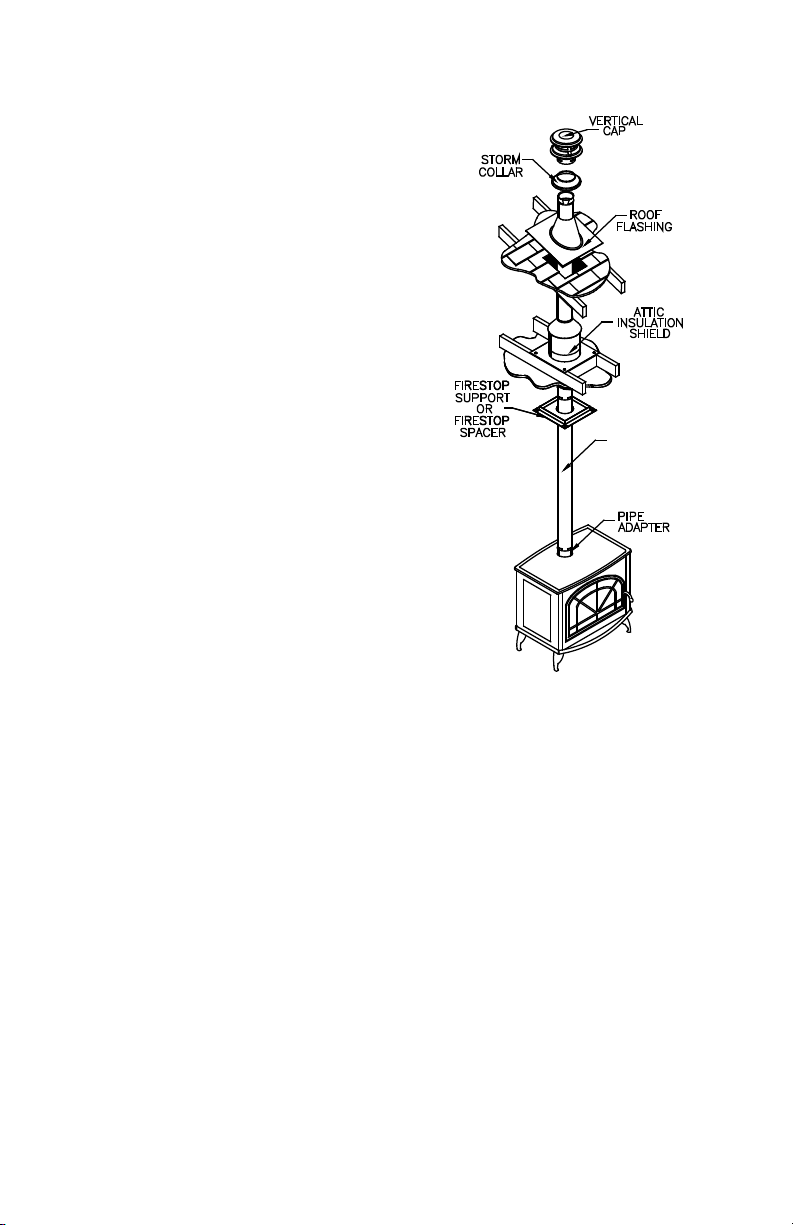
2. If the vent exit is on top of the stove
(Figure 1):
A. Place the appliance according to the
manufacturer’s instructions.
B. Drop a plumb bob to the center of the
appliance ue outlet and mark center point on
6
Page 7
the ceiling (Figure 2). At your marked center
point, cut and frame a square hole in the
ceiling for installation of the Ceiling Support or
Firestop Spacer (Figure 3). Refer to Table 1
for the dimensions of the hole.
C. Connect Pipe Adapter or Increaser Adapter
to stove: Due to the variety of different stove
collars, the Pipe Adapter will need hightemperature non-hardening sealant in order to
achieve a leak-free connection. .
D. Connect Pipe Sections. Attach PelletVent
Pro Pipe Sections by pushing male and female
ends of pipe together and twisting until pipe
is in locked position (Figure 4). PelletVent
Figure 2
PELLETVENT PRO
COMPONENT
3" & 4" CEIL ING SUPPO RT /
FIRES TOP SPACER
3" & 4" CATHEDR AL CEILI NG
SUPPO RT BOX
3" & 4" WALL THIMBL E
3" & 4" CAS WALL TH IMBLE
3" & 4" WALL THIMBL E AIR
INTAKE K IT
FRAMING DIMENSIONS
7" X 7"
10 ¾" X 10 ¾"
7 ½" x 7 ½"
9" X 9"
Table 1
Figure 3
7
Page 8
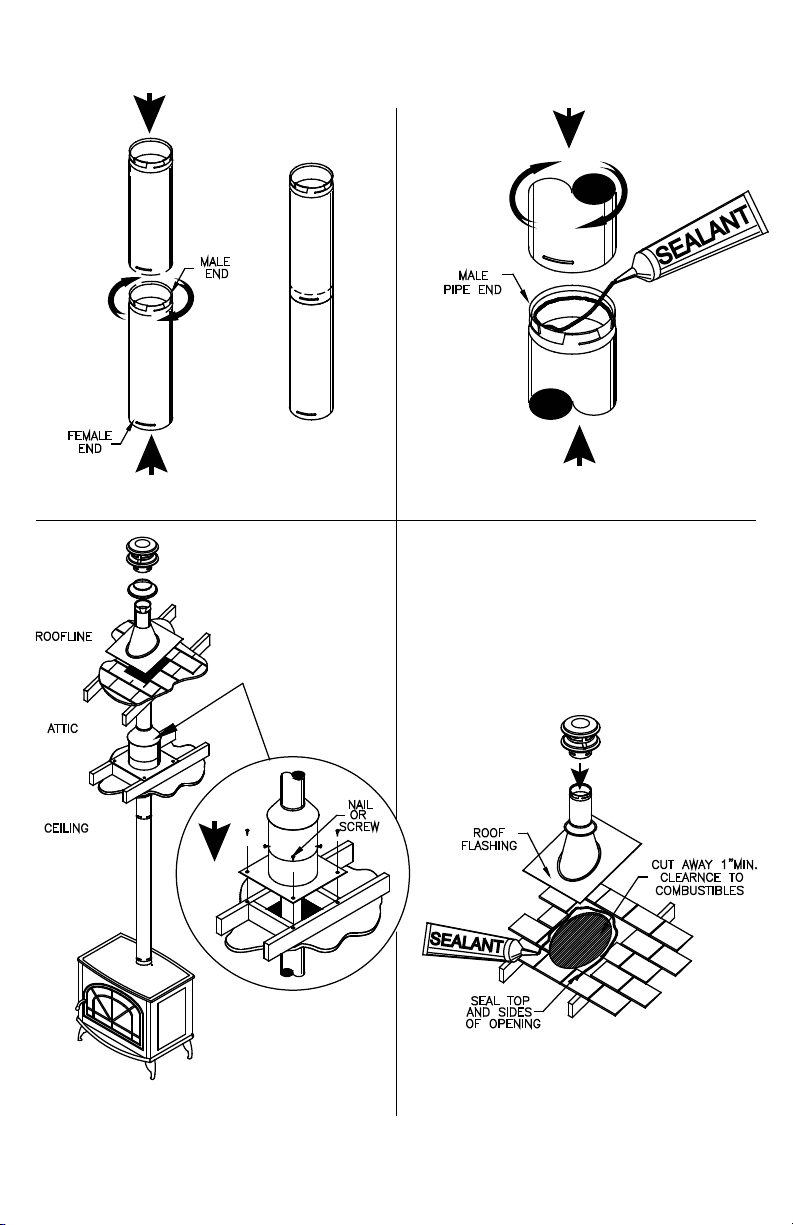
Figure 4
Figure 5
Figure 6 Figure 7
8
Page 9

Pro pipe sections do not require any sealant;
however in certain instances high temp
silicone sealant may be used. Seal connection
where the inner liners overlap for best results
(Figure 5). Screws are not needed, but 1/4”
screws can be used if desired, however, be
sure you do not penetrate the inner liner.
E. When the pipe passes through the Ceiling
Support Firestop Spacer at ceiling, tighten
bolt and clamp around pipe. Where the vent
passes through additional oors and ceilings,
always install a Ceiling Support Firestop
Spacer.
F. ALWAYS MAINTAIN AT LEAST 1”
CLEARANCE FROM COMBUSTIBLE
MATERIALS TO THE VENT PIPE.
G. When the PelletVent Pro enters the attic,
install an Attic Insulation Shield around the
vent (Figure 6). This will prevent insulation
and debris from collecting near the vent
pipe. Use (4) nails or wood screws to secure
the base of the Attic Insulation Shield to the
framed opening. Adjust the height of the Attic
Insulation Shield by sliding the top cylindrical
shield over the one from the base. Ensure
that the top of the Shield is above the level
of building insulation. Secure the Shield in
place with at least two (2) sheet metal screws
through the side of the cylindrical shield.
Attach collar around pipe, then lower to the top
of the Attic Insulation shield.
H. After lining up for the hole in roof, using
the same method as 2. (B), cut either a round
or square hole in the roof (Figure 7). Always
cut the hole with the proper clearance to the
vent pipe. Install the upper edge and sides
of Flashing under the roong materials and
nail to the roof along the upper edge and
sides (Figure 8). Do not nail across the lower
edge. Seal all nail heads with non-hardening
waterproof sealant.
I. To nish, apply non-hardening waterproof
Figure 8
Figure 9
sealant where the Storm Collar will meet the
vent and Flashing; slide Storm Collar down
until it rests upon the Roof Flashing (Figure 9).
Holding the base of Cap, rmly twist lock your
Vertical Termination Cap onto, supported Pipe
Section protruding through the roof line.
9
Page 10

PELLET VENT
PRO PIPE
Figure 10
3. If the ue exits on back of stove and an
interior installation is desired (Figure 10):
A. Place the appliance according to the
manufacturer’s instructions.
B. Connect the Tee Adapter or combine Tee
with Cleanout and Pipe Adapter then seal and
secure the Pipe Adapter to the back of the
stove.
C. Continue to assemble Pipe Sections as
described in Step 2.
4. If the ue exit is on the back of stove, and
an exterior vertical installation or partial vertical
Figure 11
installation is desired (Figure 11):
A. Place the appliance according to
manufacturer’s instructions.
B. Cut and frame a square opening in the wall
as specied in Table 1. PelletVent Pro can be
installed with the standard Wall Thimble, Wall
Thimble Air Intake Kit , or CAS Wall Thimble
for through the wall installations. If the CAS
Wall Thimble is used, refer to the PelletVent
Pro CAS Installation Instructions for direction
on how to install the Combustion Air System
(CAS). The Wall Thimble Air Intake Kit allows
combustion air to be drawn through the framed
Thimble opening, eliminating the need to
cut another opening in wall. The small ex
provided with this kit allows connection to the
Pellet Stove combustion air inlet. Note that
when installing the Wall Thimble Air Intake
Kit, the pipe will not be centered within the
framed opening. Loosely assemble both
halves of the Wall Thimble onto Pipe Section.
10
Page 11

Figure 12
Connect the exible hose with clamp to the
exterior half of the Wall Thimble. Guide the
ex through the opening in black interior half
of Wall Thimble, gently pull the ex towards
appliance (Figure 12), and if necessary trim
excess ex to required length with snips.
Secure ex to combustion air inlet of the stove
with clamp provided. Only connect metal ex
to the appliance; do not substitute or install
plastic ex. The cover plate comes installed
on the lower left corner of the thimble with
intake guard pointing downward to deect
rain. If it is desired to rotate thimble and air
inlet to another corner, remove the (2) screws
on the inlet guard and re-attach over air inlet
at new location. Secure black interior half of
the Wall Thimble to the interior wall, and the
unpainted exterior half are to be secured to the
exterior wall on both styles of thimbles (Figure
13). The Wall Thimbles adjust to t walls from
4”-8” thick. For installation in thicker walls an
extension tube may be eld fabricated.
WARNING: Do NOT install any insulation
or other material within the Wall Thimble
itself. Doing so can create a re hazard.
The Wall Thimble requires the created air
Figure 13
Figure 14
11
Page 12

Figure 15
clearance from the pipe in order to make a
safe installation. However, building insulation
may be installed around the outside of the Wall
Thimble.
C. Connect a Pipe Adapter and Pipe Section
together then seal connection to rear exhaust
outlet. Attach a Single Tee with Clean out
adapter or a Double Tee with Clean-Out
Adapter, and proceed attaching Pipe Sections
up the wall. Installing a Double Tee with
Cleanout Adapter on the exterior of wall, allows
brushing of the Horizontal Vent run through to
appliance (Figure 14).
D. Attach Wall Strap just above the tee. Wall
Straps must be placed every 8-feet along
an exterior vertical run (Figure 15). If your
exterior vertical run terminates horizontally
before penetrating the rooine, install at least
one Wall Strap on the Pipe Section before 90
Degree Elbow and Horizontal Cap (Figure 16).
Under no circumstances can a Vertical Cap be
installed adjacent to vertical wall. PelletVent
Pro offers xed and Adjustable Wall Straps
to maintain a 1”-3” clearance, as desired. If
Assemble Pipe Sections in the same manner
described in Step 2 of the general instructions.
E. Seal the exterior section of the Wall
Thimble to the wall with non-hardening
waterproof sealant. As an option, you may
also seal the gap between the pipe and Wall
Thimble with sealant.
12
Figure 16
5. If the ue exit is on back of the stove, and
a horizontal through-the-wall installation is
desired (Figure 13):
A. Place the appliance according to
manufacturer’s instructions.
B. Connect the Appliance Adapter and
sufcient Pipe Sections the seal and secure to
back of stove. Horizontal Pipe sections must
penetrate Wall Thimble and extend at least 6”
Page 13

Figure 17
beyond the exterior wall after Horizontal Cap
is attached. If you are burning Corn you must
use a Round Horizontal Cap. Pipe Sections
exposed to exhaust gases between wall and
Cap must have a Stainless Steel outer liner.
The Round Horizontal Cap can be swiveled to
be directed away from nearby objects (fence,
plants, etc.), but must still be pointing in a
generally downward direction. Important:
Horizontal Caps must be pointed in a
downward direction to insure rain and snow do
not enter the cap, and cause potential damage
to the appliance.
C. Follow the below listed NFPA 211 rule for
distance of exit terminal from windows and
openings:
NFPA 211 (2006 ed.) Section 10.4 Termination:
10.4.5
(1) The exit terminal of a mechanical draft
system other than a direct vent appliance
(sealed combustion system appliance) shall be
located in accordance with the following:
(a) Not less than 3 ft (.91m) above any forced
air inlet located within 10 ft. (3m).
(b) Not less than 4 ft. (1.2m) below, 4 ft.
(1.2m) horizontally from or 1 ft. (305mm)
above any door, window or gravity air inlet
into any building
PELLET VENT
PRO PIPE
(c) Not less than 2 ft. (0.61m) from an
adjacent building and not less than 7
ft. (2.1m) above grade when located
adjacent to public walkways.
If using the Wall Thimble Air Intake Kit, the
installation may be considered a direct vent
system, as dened by NFPA 211. Check with
local building ofcials for clarication. If so, the
clearances for the exit terminal are as follows:
For an appliance with an input of 10,000 Btu/h
(2930 W) or less, the vent terminal shall be
located at least 6" from any opening into a
building. For an appliance with an input of
greater than 10,000 Btu/h but less than 50,000
Btu/h (14650 W), the vent terminal shall be
located not less than 9" from any opening into
a building. For an appliance with an input over
50,000 Btu/h (14650 W), the vent terminal
shall be located not less than 12" away from
any building opening. The bottom of the vent
terminal and air intake must be located a
minimum of 12" above grade.
6. If it is desired to attach to an existing
6”-8” DuraTech, DuraPlus or DuraPlus HTC
chimney, either roof supported or ceiling
supported (Figure 17):
A. Remove any existing connector pipe,
13
Page 14

adapter or connector going into the ceiling
support box.
B. Visually inspect with a ashlight the
condition of the interior of the chimney
for cleanliness and structural integrity. All
evidence of soot and creosote must be
removed from the existing chimney system.
If you doubt your ability to accomplish this,
contact a certied chimney sweep. Do not
use chemical cleaners, as these can possibly
damage the inside of the chimney. Do any
required maintenance on the existing chimney
system at this time.
C. Install a DVL/DuraBlack Chimney Adapter product stock numbers (6”) 8674, (7”) 8774, or
(8”) 8874 - in the existing Ceiling Support Box.
Note that the DVL/DuraBlack Chimney Adapter
only connects to Dura-Vent chimney systems.
D. Connect the appropriate size Chimney
Adapter to the DVL/DuraBlack Chimney
Adapter.
E. Connect the appliance to the Chimney
Adapter using an Appliance Adapter, lengths
of pipe as required, and an Adjustable Length
pipe. Slide the Adjustable Length down over
the top pipe section, position the installation
vertically plumb, then slip the Adjustable
Length up and twist lock it to the Chimney
Adapter. Once all the components are rmly
seated and properly aligned, carefully drill
three 1/8” diameter holes through the outer
sleeve only in the center of the slots located
at the bottom of the Adjustable Length pipe.
Do not penetrate the inner liner. Use (3)
1/4” length sheet metal screws to secure the
Adjustable Length pipe.
14
14
Figure 18 Figure 19
Page 15

INSTALLATION INTO A MASONRY
PELLET VENT PRO
FIREPLACE
1. Have the masonry chimney inspected
by a certied chimney sweep or installer to
determine its structural condition.
2. Carefully read the pellet stove or insert
installation instructions.
3. Measure and record the dimensions as
shown in (Figure 18).
4. Use dimension “A” to determine total pipe
requirements. Add 12 additional inches to
ensure the termination is an adequate distance
above the rooine.
5. The gross pipe required will be dimension
“A” plus 12 inches. Five feet of this will be Flex
Pipe. The remainder will be rigid pipe. For
each joint, subtract 1-1/2 inches to allow for
the overlap. You may need extra pipe, or an
PELLET VENT PRO
VERTICAL CAP
adjustable length pipe section to achieve the
correct height.
6. Assemble the rst rigid Pipe Section to
the Flex Pipe, ensuring that the “UP” arrows
shown on the pipe labels are, in fact, pointing
up. Push the sections together and twist to
lock. Screws are not required for a rm lock,
however, should it be desired to use them, use
stainless steel sheet metal screws 1/4-inch
long - do not penetrate the inner liner of the
pipe.
7. Repeat this process for the remainder of
the pipe sections, and lower the assembly
down the chimney as shown in (Figure 19).
Lower it below its normal position in order
Figure 20
RIGID PIPE
Figure 21
Figure 22
15
15
Page 16

Figure 23
Figure 25
Figure 24
16
Page 17

to connect the Flex Pipe to the pipe on the
appliance. It may be necessary to tie a line to
the top section, to pull it back up later.
8. In making the connection at the appliance,
congurations other than the one shown
in (Figure 20) may be made. It may be
necessary to contact the manufacturer of the
unit to determine exactly what may or may not
be done to make the correct connection. Some
typical arrangements are shown in (Figures 21
and 22). An Appliance Adapter or Increaser
Adapter may be needed, depending on the exit
size of the stove or insert collar.
9. If a Tee or Tee Adapter is necessary to make
the connection, as shown in (Figure 22), the
Tee has a removable Clean out Adapter on
its base to enable cleaning. The Tee Support
Bracket to hold the Tee to the rear of the
appliance is mandatory. If it is desired to mount
the Tee Support to the rear of the stove, obtain
approval from the manufacturer of the stove
before drilling, tapping, or performing any other
alterations to the appliance.
10. Connect the appliance to the coupling on
the bottom of the Flex Pipe, by twisting to the
locked position. Push the appliance into the
replace to its nal resting place. Go to the top
of the chimney and pull the vent system up to
its desired height.
11. For support at the termination of the
PelletVent, use a Tall Cone Flashing, and a
Storm Collar. This will require 14 inches of
pipe above the top of the masonry chimney.
Pull the pipe up through the ashing to the
desired height. Mark location of the Storm
Collar. Slip the Storm Collar down over the
pipe and afx it to the pipe with a 1/4”-long
stainless steel sheet metal screw (Figures 23
& 24). The Storm Collar will then support the
entire vent system. Install the Cap. Seal the
joint at the Storm Collar, and any other joints
or seams which may appear suspect. (Figure
Figure 26
25) shows a Tall Cone Flashing modied to t
a chimney where the tile liner protrudes above
the masonry, as another alternate termination
technique. This completes the masonry
installation.
INSTALLATION THROUGH SIDE OF
MASONRY CHIMNEY
1. Set the appliance in its nal location and
mark the center of the hole where the pipe is
to penetrate the masonry chimney. Ensure
that you comply with the manufacturer’s
specications in regards to clearance and
distances from combustible surfaces.
2. The PelletVent Pro system is assembled
essentially the same as previously described
for installation in an existing masonry chimney
with the exceptions listed:
A. No Flex Pipe is required, unless the
masonry chimney has an offset. If an offset
exists, then a Flex Pipe will be needed from
17
Page 18

Figure 27
the offset down to opening in masonry.
B. A Tee Section is installed at the bottom end
of the vertical pipe (Figure 26).
C. A Reduction Collar or a Trim Collar is
required to go around the pipe section that
passes through the masonry to give it a
nished look.
3. It will be necessary to break out the
masonry around the location of the pipe center
line mark to a diameter of at least 4 inches for
3 inch pipe, and at least 5 inches in diameter
for 4 inch pipe.
4. Install the Tee on the bottom of the vertical
pipe system and lower it down the chimney
until the center of the branch of the Tee is level
with the center of the hole in the masonry.
Connect horizontal pipe section to the Tee
branch.
5. Holding the pipe at the proper elevation,
install the Storm Collar and Cap, as described
in Step 11 for the replace installation.
6. Connect the horizontal Pipe Section through
the masonry to the Tee by pushing it through
the hole in the masonry, and lining it up with
the branch of the Tee. Then insert Pipe Section
into the Tee, while twisting to lock it.
7. Once the horizontal Pipe Section is in place,
the space between the pipe and the masonry
may be lled with high temperature grout, if
desired (Figure 27).
8. Install the Reduction Collar or Trim Collar
18
over rough opening, then 90° Elbow, and
the required vertical Pipe Sections down to
the appliance. An Adjustable Pipe length will
probably be needed, as well as an Appliance
Adapter or Increaser Adapter.
9. Conduct a nal inspection of the entire job,
and review the manufacturer’s operating and
installation instructions once more, before
ring the appliance.
INSTALLATION IN A
CATHEDRAL CEILING
1. Mark a line on the side of the Cathedral
Ceiling Support Box to correspond to the line
of the roof pitch, as shown in (Figure 28).
Allow for the Support Box to protrude below
the low side of the nished ceiling a minimum
of 2 inches.
2. Position the appliance at its proper
location on the oor. Pay close attention to
the manufacturer’s installation instructions
regarding the clearance to combustibles, etc.
Position appliance so Support Box will not
interfere with roof rafters or other structural
framing.
3. Run a plumb line from the center of the ue
exit on the stove to the ceiling. Mark the point
on the ceiling where the plumb line intersects.
This represents the center of the support box.
Drill a small hole through the ceiling at this
point, so it can be located from the top of the
roof.
4. From the roof, locate and mark the outline of
the Support Box.
5. Remove shingles or other roof covering as
necessary to cut the rectangular hole for the
Support Box. Cut the hole 1/8-inch larger than
the dimensions of the Support Box (Figure
29). The rectangular hole should be centered
on the small hole which you drilled through the
ceiling to mark the location. Again, verify that
you are not cutting through rafters or framing
Page 19

Figure 28
Figure 29
Figure 30
Figure 31
19
Page 20

Figure 32
Figure 33
Figure 34
members.
6.
Run the Support Box through the roof as shown
in (Figure 30), and place it so that the bottom of
the Support Box protrudes at least 2 inches below
the low side of your opening in the nished ceiling
(Figure 31). Align the Support Box vertically and
horizontally with a level. Temporarily tack the
Support Box in place through the inside walls and
into the roof sheathing.
7. If the Support Box protrudes the rooine use
tin snips to cut from the top corners down to
the roof line, and fold the resulting ap over the
roof sheathing (Figure 32). Before nailing it to
the roof, run a bead of non-hardening sealant
around the outside top edges of the Support
Box so as to make a seal between the box and
the roof. Clean out any combustible material or
debris from inside the Support Box.
8. Place the Support Clamp, included with
Support Box, loosely around Pipe Sections
running through hole in Support Box (Figure
33).
9. Connect the necessary amount of Pipe
Sections to reach the stove and extend at least
12-inches above the roof before attaching
Termination Cap (Figure 32).
10. After all PelletVent Pro Pipe Sections and
components are assembled and connected
down to the appliance seal and secure the
Appliance Adapter to stove. Using a level,
make slight adjustments in the position of the
appliance until the pipe is truly vertical. Tighten
the bolts in the Support Clamp (Figure 33).
Note that the overall length of the PelletVent
Pro system can be no longer than 42 feet.
11. Slip Roof Flashing over the supported
Pipe Section(s) protruding through the roof.
Apply sealant to underside of Roof Flashing
along upper edge and sides. Secure the base
of Roof Flashing to the roof with roong nails
(Figure 34). Ensure that the roong material
overlaps the top edge of the Roof Flashing.
20
Page 21

CLEANING AND MAINTENANCE
1. Have your system cleaned by a certied
chimney sweep if you have doubts about your
ability to clean it. Use a plastic or exible steel
brush. Do not use a stiff brush that will scratch
the stainless steel liner of your system.
2. PelletVent Pro systems must be installed
so that access is provided for inspection and
cleaning.
3. The system should be inspected at least
once every month during the heating season.
4. Do not use chemical cleaners. They can
damage the vent pipe.
5. To increase the life PelletVent Pro, coat
all exterior metal parts with high temperature,
rustproof paint. This is highly recommended,
particularly in areas near the ocean.
6. In case of a chimney re, close all
appliance draft openings shut off appliance
and call your Fire Department. Do not use the
appliance or vent until it has been inspected
for possible damage and silicone gaskets
replaced.
7. Dura-Vent is not responsible for ue byproducts that might discolor roofs or walls.
21
Page 22

22
Page 23

23
Page 24

M&G DURAVENT WARRANTY
M&G DuraVent, Inc. (“DuraVent”) provides this limited lifetime warranty for all of its products to the original purchaser, with the exception of Ventinox (lifetime),
DuraBlack (ve years) and all Termination Caps (ve years). Subject to the limitations set forth below, DuraVent warrants that its products will be free from
substantial defects in material or manufacturing, if properly installed, maintained and used. This Warranty is non-transferable with the exception of Ventinox
which is transferable from the original homeowner to the buyer of the home for a period of ten (10) years. This warranty does not cover normal wear and tear,
smoke damage or damage caused by chimney res, acts of God, or any produc t that was: (1) purchased other than from an authorized DuraVent dealer, retailer
or distributor; (2) modied or altered; (3) improperly serviced, inspected or cleaned; or (4) subject to negligence or any use not in accordance with the printed
materials provided with the product as determined by DuraVent. This limited lifetime warrant y applies only to par ts manufactured by DuraVent.
DuraVent provides the following warranties for its products: One Hundred Percent (100%) of the purchase price or MSRP at time of purchase, whichever is lower,
for 15 years from the date of purchase, and Fift y Percent (50%) thereafter, except for the following limitations: Ventinox liner and components in wood, oil, wood
pellet, and gas installations are warranted at One Hundred Percent (100%) for the lifetime of the original homeowner; Ventinox 316 liner and components for
coal burning installations which are warranted One Hundred Percent (100%) for ten years; all Termination Caps and DuraBlack® are warranted at One Hundred
Percent (100%) for ve years, and at Ten Percent (10%) thereafter.
All warranty obligations of DuraVent shall be limited to repair or replacement of the defective product pursuant to the terms and conditions applicable to each
product line. These remedies shall constitute DuraVent’s sole obligation and sole remedy under this limited warranty. This warranty provides no cash surrender
value. The terms and conditions of this limited lifetime warranty may not be modied, altered or waived by any action, inaction or representation, whether oral
or in writing, except upon the express, written authority of an executive ocer of DuraVent.
VENTI NOX WAR RANTY CON DITIONS
Liner and Component warranties contained herein are subject to the following conditions: (1) The Liner and Components must be installed according to DV’s
installation instructions; (2) The Liner and Components are used only to line or reline chimneys venting residential appliances for which the liner was intended;
and (3) documented annual inspection of the Liner and Components and maintenance as deemed necessary, beginning one year after the date of installation
and continuing throughout the warranty period, by a Nationally Certied Chimney Sweep or VENTINOX® installer. The Liner and Components warranty is further
subject to compliance with the following requirements throughout the warranty period: The chimney must have a chimney cap and chemical chimney cleaners
must not be used when cleaning the Liner or Components. Plastic-bristle ue cleaning brushes are recommended. Corn, biofuels, driftwood or other wood
containing salt, preservative-treated lumber, plastic and household trash or garbage, or wood pellets containing such materials must not be burned in the
appliance or replace. In case of a chimney re, the chimney must be inspected and approved by a certied Chimney Sweep before reuse. After each annual
inspection, maintenance, and cleaning, the certied Chimney Sweep must ll out and date the appropriate section of the warranty card provided with the
chimney liner.
LIMITATIONS ON INTERNET SALES:
Notwithstanding any other terms or conditions of this limited lifetime warranty, DuraVent provides no warranty for the following specic products if such
products are both: (a) purchased from an Internet seller; and (b) not installed by a qualied professional installer: DuraTech®, DuraPlus HTC®, PelletVent Pro®,
FasnSeal®, and DuraVent’s relining products including DuraLiner®, DuraFlex® 304, DuraFlex® 316, DuraFlex® Pro, DuraFlex® SW, and Ventinox®. For purposes of
this warranty, a trained professional installer is dened as one of the following: licensed contractors with prior chimney installation experience, CSIA Certied
Chimney Sweeps, NFI Certied Specialists, or WETT Certied Professionals.
DuraVent reserves the right to inspec t defective produc t to determine if it qualies for replacement under the terms of this limited lifetime warranty. All warranty
claims must be submitted with proof of purchase. Labor and installation costs are not covered under this warranty. To obtain warranty service contact DuraVent
promptly at DuraVent Warranty Service, 902 Aldridge Rd., Vacaville CA 95688, or call 800-835-4429.
WHERE LAWFUL, DuraVent DISCLAIMS ALL OTHER WARRANTIES, INCLUDING BUT NOT LIMITED TO IMPLIED WARRANTIES OF MERCHANTABILITY AND FITNESS
FOR A PARTICULAR PURPOSE. IN NO EVENT WILL DuraVent BE LIABLE FOR INCIDENTAL, CONSEQUENTIAL, PUNITIVE OR SPECIAL DAMAGES OR DIRECT OR
INDIRECT LOSS OF ANY KIND, INCLUDING BUT NOT LIMITED TO PROPERTY DAMAGE AND PERSONAL INJURY. DuraVent’S ENTIRE LIABILITY IS LIMITED TO THE
PURCHASE PRICE OF THIS PRODUCT. SOME STATES DO NOT ALLOW LIMITATIONS ON IMPLIED WARRANTIES, OR THE EXCLUSION OR LIMITATION OF INCIDENTAL
OR CONSEQUENTIAL DAMAGES, SO THE ABOVE LIMITATIONS AND EXCLUSIONS MAY NOT APPLY TO YOU. THIS LIMITED WARRANT Y GIVES YOU SPECIFIC LEGAL
RIGHTS, AND YOU MAY ALSO HAVE OTHER RIGHTS THAT VARY FROM STATE TO STATE.
For the most up-to-date installation instructions, see www. duravent.com
REV 7.20.2010
M&G DuraVent, Inc. PO B ox 1510 Vacaville CA 95696-1510
Manufactured in Vacaville CA and Albany NY
Customer Service Support 800-835-4429 707-446-4740 FAX www.duravent.com
PelletVent Pro is a registered trademark of the M&G DuraVent, Inc.
All rights reserved. Made in the USA. M&G DuraVent is a member of M&G Group. ©2011
L550 04/2011
 Loading...