

Page 1
Installation Instructions
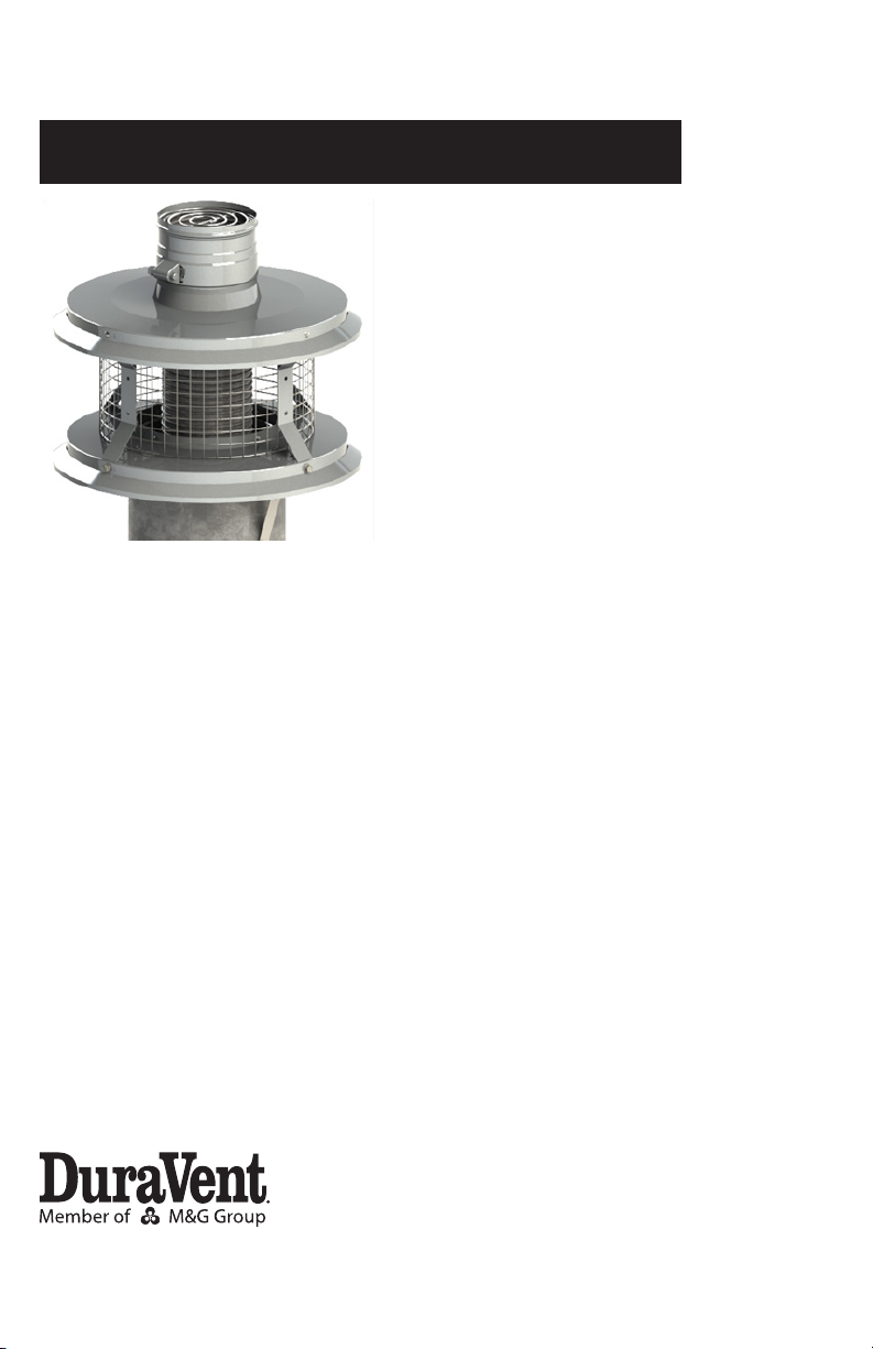
FNS 80/90
Combined Category I and
IV venting for Gas-Burning
Appliances
For the most up-to-date installation instructions, see www.duravent.com
CONTENTS
LISTING. . . . . . . . . . . . . . . . . . . . . . . . . . . . . . . . . . . . . . . . . . . .. . . . . . . . . . . . . . . . . 3
NOTES / A PPLICATION . . . . . . . . . . . . . . . . . . . . . . . . . . . . . . . . . . . . . . . . . . . . . . . . . . 3
CLEARANCES TABLE 1. . . . . . . . . . . . . . . . . . . . . . . . . . . . . . . . . . . . . . .. . . . . . . . . . . 3
PRIOR TO INSTALLATION. . . . . . . .. . . . . . . . . . . . . . . . . . . . . . . . .. . . . . . . . . . . .3
INSTALLATION OF LINER. . . . . . . .. . . . . . . . . . . . . . . . . . . . . . . . .. . . . . . . . . . . .5
MAINTENANCE . . . . . . . . . . . . . . . . . . . . . . . . . . . . . . . . . . . . . . . . . . . . . . . . . . . . . .7
WARRANTY. . . . . . . . . . . . . . . . . . . . . . . . . . . . . . . . . . . . . . . . . . . . . . . . . . . . . . . . . . .8
®
Page 2
A MAJOR CAUSE OF VENT RELATED FIRES IS FAILURE
TO MAINTAIN REQUIRED CLEARANCES (AIR SPACES)
TO COMBUSTIBLE MATERIALS. IT IS OF THE UTMOST
IMPORTANCE THAT DURAVENT PRODUCTS BE INSTALLED
ONLY IN ACCORDANCE WITH THESE INSTRUCTIONS.
WARNING
CARBON MONOXIDE POISONING
HAZARD. Failure to follow the steps
outlined below for each appliance
connected to the venting system being
placed into operation could result in
carbon monoxide poisoning or death.
• Examine all components for possible
shipping damage prior to installation;
• Read all instructions before beginning
the installation and follow these
instructions exactly as written.
• Proper joint assembly is essential for a
safe installation. Check the integrity of
ALL joints upon completion of assembly
• This venting system must be free to
expand and contract under normal
operation.
• Assure unrestricted vent movement
where required through walls, ceilings
and roof penetrations.
• This venting system must be supported
in accordance with these instructions.
• Do not mix pipe, ttings, or joining
methods from dierent vent system
manufacturers. Do not use adhesives
of any kind with this venting system.
Acceptance of the installed system is
dependant on full compliance with
these installation instructions.
WARNING
Risk of carbon monoxide poisoning
or re due to joint separation or pipe
breakage.
Keep these instructions for future
reference.
Dear Customer, Installer, or End User:
We welcome any comments regarding
matters pertaining to our DuraVent products.
We welcome any ideas, input or complaints
to help improve our product oering.
If you are searching for tech support or
product information, please phone us at
800-835-4429.
Or email us at:
techsupport@duravent.com
LISTED
MH6357
Page 3
LISTING
M&G DuraVent's FNS 80/90 Combination
Cat I and Cat IV gas vent system is designed
and UL listed for use with approved M&G
Duravent / Security Chimneys special gas
vent components only! Listed to applicable
portions of ULC S636/UL1738, UL1777, and
UL441.
GENERAL INSTALLATION NOTES
Read these instructions before beginning.
You must follow these installation
instructions when installing the FNS 80/90
system. This is a supplemental instruction to
other DuraVent listed instructions that are
used during this installation.
APPLICATION
The FNS 80/90 system is a tested and listed
exhaust vent for the replacement of one
Category I gas red appliance with a high
eciency appliance in an existing Type B
common vent system. In a typical common
IMPORTANT
The vent system must be installed in
accordance with local code requirements
and appropriate National Codes: In the
US: NFPA 54 / ANSI Z223.1 National Fuel
Gas Code or the International Fuel Gas
Code.
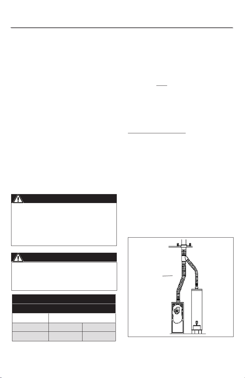
vent Type B setup (Fig.1), two Category I
(Cat I) appliances vent into one common
vent that conveys ue products outside the
building. In many appliance retrots, one
Cat I appliance is removed, and replaced
with a higher eciency (typically a Cat
IV) condensing appliance. The new Cat IV
appliance is NOT permitted to be vented with
B Vent, but requires a vent system engineered
for a dierent exhaust requirement.
Condensing appliances have much lower
exhaust temperatures, which create
signicant amounts of acidic condensate.
Using the FNS 80/90 solution, a special
stainless steel Cat IV liner is installed within
the existing Cat I vent. This ex handles the
Cat IV ue products, while the remaining
Cat I appliance uses the annular space
around the liner to exhaust ue products
to the outside via natural draft (Fig.2). A
patent pending termination is engineered
to provide separate exhaust exit paths for
each appliances's exhaust system (Fig.2). The
combination of these systems helps both
operate more eectively.
PRIOR TO INSTALLATION: RELINING
COMMON VENTED B VENT SYSTEMS
When relining common vented B-Vent (or
WARNING
CARBON MONOXIDE POISONING HAZARD
Failure to follow these installation
instructions could result in personal
injury or death
Table 1
Clearance to Combustibles
Type B Gas Vent Unchanged Unchanged
VENT PIPE ORIENTATION
Vertical Horizontal
3
TYPICAL
COMMON
VENTED
CATEGORY I
INSTALLATION
Figure 1
Page 4

CAT I EXHAUST
PATH
CAT IV EXHAUST
PATH
Figure 2
other approved factory built vent), special
care must be taken. Prior to reline work
being started:
BIRDSCREEN
FNS FLEX
COLLAR
TERMINATION
CAP
CAP MOUNT
STRAPS /
HARDWARE
FNS FLEX
B VENT
PRE-EXISTING
CAT IV
FIRESTOP /
HARDWARE
POLYPRO
TO FNS FLEX
ADAPTER
CATEGORY
IV EXHAUST
ENTRY
FIG.5
CAT I
EXHAUST
ENTRY
Ensure the new proposed vent system
Figure 3
is appropriate for the two appliances in
question. For the Category IV appliance,
reference the OEM Appliance manual for
information on min/max vent run and vent
diameter requirements. OEM guidance
should include maximum number of elbows
and related pressure-drops. The total vent
length from the appliance to the termination
should not be greater than the maximum
Table 2 - Equivalent Length Chart
2" Equivalent Length 3" Equivalent Length 4" Equivalent Length 5" Equivalent Length
1-ft Rigid Pipe 1-ft 1-ft 1-ft 1-ft
1-ft SS FNS (or
Secure Seal)Flex
1-ft Flex Pipe
45 Elbow 3-ft 3-ft 5-ft 6-ft
90 Elbow 5-ft 7-ft 12-ft 14-ft
Tee 9-ft 12-ft 19-ft 21-ft
Same as rigid pipe (or
elbows)
0.4-ft
(updsized one diameter)
Same as rigid pipe (or
elbows)
0.6-ft
(updsized one diameter)
Same as rigid pipe (or
elbows)
0.6-ft
(updsized one diameter)
Same as rigid pipe (or
elbows)
N/A
4
Page 5

Equivalent Vent Length (EVL) specied by the
appliance manufacturer. If specic guidance
is not oered by the appliance manufacturer
regarding EVL for vent components, the
general guidelines in Table 2 may be used for
PolyPro, FNS, FNS W2 and Security Chimney
Secure Seal product.
For sizing of the remaining Cat I appliance
into the B Vent, reference Table 3. This Table
shows B Vent diameter, inner Cat IV liner
diameter, and the resulting annular space in
terms of an "Equivalent" diameter. This data
takes into account ow restriction on the Cat
I ue introduced from the inner ex and has
been experimentally conrmed. Ensure this
"equivalent" diameter is appropriate for your
remaining Cat I appliance via use of Type B
Gas Vent sizing tables / NFPA54 (Chapter 13).
Treat the connector from the Cat I appliance
and the common vent as a single appliance
vent with the height, length, osets, etc
and verify that the tables conrm adequate
capacity of this annular space before
proceeding.
After conrming the combination vent
system is appropriate for your installation,
inspect the physical condition of existing
B Vent. The B vent must be inspected for
evidence of damage, internal ue blockage,
appropriateness of components including
restops, supports, etc. The inspection must
also ensure the original installation meets
current codes for termination location,
height, etc. Clean and repair as needed to
bring the vent system into compliance.
4a
4b 4c
Figure 4
INSTALLATION OF LINER WITHIN B VENT
Reference Fig.3 for the components required.
Inspect the area where the Cat I exhausts
come together- typically a "Tee" or "Wye". It is
critical that when the Cat IV liner is installed,
it maintain a slope of at least 45° downward
towards the appliance (Fig.4) throughout
the vent run- This is to ensure proper ow of
condensate back to the appliance / drain. If
the inlet end of the existing (common) B vent
is a tee, either the ex for the Cat IV appliance
vent must route through the bottom end of
the tee (Fig.4a) or the tee should be replaced
with a "wye" (Fig.4b), so the ex can route
through the inclined snout of the wye (to
maintain proper slope). Do not install per
Fig.4c!
Table 3 - Annular Space- Effective Remaining B Vent Diameter
2" Cat IV Liner Dia 3" Cat IV Liner Dia 4" Cat IV Liner Dia 5" Cat IV Liner Dia
5" B Vent 4" 3" N/A N/A
6" B Vent 5" 4" 4" N/A
7" B Vent 6" 5" 5" 4"
8" B Vent 6" 6" 6" 5"
5
Page 6

APPLY SEALANT
BIRD-SCREEN
SLIDE FLEX
UP TO
SEAL
Figure 5a- 2" Flex
APPLY SEALANT
APPROX 3/4"
FROM TOP
BIRD-SCREEN
Figure 5b- 3"-5" Flex
If the lower tee or wye needs to be replaced,
determine the existing brand of B Vent. If
the B Vent is DuraVent, the appropriate Tee
or Wye can be purchased and connected as
is. If the B Vent is not DuraVent, purchase a
"Female Adapter" which allows connection to
non-DuraVent B Vent, and the DuraVent tee
or wye desired.
1. Remove the Cat I appliance being
replaced, the associated B Vent pipe, and
existing termination cap.
2. Measure vent run, cut ex to length,
ensure 1 ft of excess ex. Remove burrs from
ex for ease of install.
4. Connect ex to termination cap:
4a. If installing 2" Flex: Flip the
termination cap upside down and apply
a generous amount of high temperature
non-hardening silicone around the outer
ange edge of the FNS Flex Collar (Fig.5a).
Once applied, ip the termination cap back
upright and carefully lower cap onto ex
so that the silicone ange is seated inside
the 2” ex. Tighten hose clamp to secure
the ex to the termination cap.
4b. If installing 3”-5” ex: Run the ex
through the termination cap until ex is
¾” from exit at the top of the cap. Tighten
the hose clamp to secure the ex into
position. Apply a generous bead of high
temperature non-hardening silicone
(Fig.5b) to seal ex to the inner diameter
of the termination cap.
5. Lower cap to B-Vent and ax with
hardware / mount straps to the vent pipe.
Strap can be trimmed if desired.
6. Compress / Install Bird Screen Ring into
Flex collar groove. (Fig.5a/b)
3"-5"
APPLY
SEALANT
TOP (CAP) side of install:
3. Route ex through B Vent, leave 8" excess
at top. Ensure ex does not go beyond 45
degree anywhere along the vent run for
proper condensate handling. Ensure ex is
installed so the arrow goes in direction of
exhaust ow
POLYPRO
/ FLEX
ADAPTER
FIRESTOP
Figure 6- Appliance Side
Connection
6
Page 7

IMPORTANT
When installing FasNSeal Flex, the
direction of exhaust ow is away
from the appliance. There is an arrow
printed on each section of liner and
components that will point in the
direction of the exhaust gas. You can
conrm the liner is installed correctly
by running your ngernails up the
inside wall of the liner. If the direction
is correct your nails will catch at the
seams of the inner wall. If it is incorrect
your nails will slide smoothly across
the inner surface.
LOWER (Appliance) side of install (Fig.6)
1. Flex should stick outside B Vent minimum
3”, maximum 5” (trim if needed).
2. Apply generous amount of silicone to ex
and PolyPro / Flex adapter (or other approved
DuraVent or Security Chimneys product).
Insert ex into adapter and tighten hose
clamp.
3. Install restop onto adapter, fasten to
B-Vent using supplied hardware.
4. Continue vent run to the appliance per the
appropriate instruction.
MAINTENANCE
Have your venting system checked annually.
This can be done by the same technician
who inspects & services the appliance.
Recommended areas to inspect are as
follows:
- Check areas of the Venting System which
are exposed to the elements for wear or
damage. If damage is found, the components
should be replaced immediately.
- Where possible, look into the Termination
Cap to verify no foreign material is there to
block the vent. Remove any foreign material
found.
- Where practical, inspect joints to verify
Figure 7- Disassembly of Cap
that no Pipe Sections or Fittings have been
disturbed, and consequently loosened. Also
check mechanical supports such as Wall
Straps, support plates, etc for rigidity.
Should the termination need to be removed,
loosen ex hose clamp and unfasten from
B-Vent. If internal access is needed, the four
screws holding the termination top to the
termination base may be removed and the
termination top will lift o (Fig.7).
7
Page 8

M&G DURAVENT LIMITED LIFETIME WARRANTY
M&G DuraVent, Inc. (“DuraVent”) provides this limited lifetime warranty for all of its products with the exception of Ventinox® (lifetime), and
PolyPro® (ten years). Subject to the limitations set forth below, DuraVent warrants that its products will be free from defects in material or
manufacturing, if properly installed, maintained and used. DuraVent products are fully warranted if installed only by a professional installer.
This Warranty is transferable from the original homeowner to the buyer of the home. This warranty does not cover normal wear and tear,
smoke damage or damage caused by chimney res, acts of God, or any product that was: (1) purchased other than from an authorized
DuraVent dealer, retailer or distributor; (2) modied or altered; (3) improperly serviced, inspected or cleaned; or (4) subject to negligence or
any use not in accordance with the installation instructions included with the product as determined by DuraVent. Installation instructions are
available online at www.duravent.com under Support/Literature and through our Customer Service Department 800-835-4429 or
customerservice@duravent.com. This limited lifetime warranty applies only to parts manufactured by DuraVent.
DuraVent provides the following warranties for its products: One Hundred Percent (100%) MSRP 15 years from the date of purchase, and Fifty
Percent (50%) thereafter, except for the following limitations on: all Termination Caps and DuraBlack® are warranted at One Hundred Percent
(100%) for ve years.
All warranty obligations of DuraVent shall be limited to repair or replacement of the defective product pursuant to the terms and conditions
applicable to each product line. These remedies shall constitute DuraVent’s sole obligation and sole remedy under this warranty. This warranty
provides no cash surrender value. The terms and conditions of this warranty may not be modied, altered or waived by any action, inaction or
representation, whether oral or in writing, except upon the express, written authority of an executive ocer of DuraVent.
Corn, bio-fuels, driftwood or other wood containing salt, preservative-treated lumber, plastic and household trash or garbage, or wood pellets
containing such materials must not be burned in the appliance or replace. In case of a chimney re, the chimney must be inspected and
approved by a certied Chimney Sweep before reuse. After each annual inspection, maintenance, and cleaning, the certied Chimney Sweep
must ll out and date the appropriate section of the warranty card provided with the chimney liner.
LIMITATIONS ON INTERNET SALES: Notwithstanding any other terms or conditions of this Limited Lifetime Warranty, DuraVent provides no
warranty for the following specic products if such products are not installed by a qualied professional installer: DuraTech®, DuraPlus HTC®,
DuraChimney® II, PelletVent Pro®, DirectVent Pro®, FasNSeal®, FasNSeal® W2, FasNSeal® Flex, and PolyPro®, and M&G DuraVent’s relining
products including DuraLiner®, DuraFlex® (SW, Pro, 316, 304), and Ventinox®. For purposes of this warranty, a trained professional installer is
dened as one of the following: licensed contractors with prior chimney installation experience, CSIA Certied Chimney Sweeps, NFI Certied
Specialists, or WETT Certied Professionals.
DuraVent must be notied and given the opportunity to inspect defective product prior to replacement under the terms of this limited lifetime
warranty. All warranty claims must be submitted with proof of purchase. Labor and installation costs are not covered under this warranty. To
obtain warranty service contact: DuraVent Warranty Service, 877 Cotting Ct., Vacaville CA 95688, or call 800-835-4429.
WHERE LAWFUL, DURAVENT DISCLAIMS ALL OTHER WARRANTIES, INCLUDING BUT NOT LIMITED TO IMPLIED WARRANTIES OF
MERCHANTABILITY AND FITNESS FOR A PARTICULAR PURPOSE. IN NO EVENT WILL DURAVENT BE LIABLE FOR INCIDENTAL, CONSEQUENTIAL,
PUNITIVE OR SPECIAL DAMAGES OR DIRECT OR INDIRECT LOSS OF ANY KIND, INCLUDING BUT NOT LIMITED TO PROPERTY DAMAGE AND
PERSONAL INJURY. DURAVENT’S ENTIRE LIABILITY IS LIMITED TO THE PURCHASE PRICE OF THIS PRODUCT. SOME STATES DO NOT ALLOW
LIMITATIONS ON IMPLIED WARRANTIES, OR THE EXCLUSION OR LIMITATION OF INCIDENTAL OR CONSEQUENTIAL DAMAGES, SO THE ABOVE
LIMITATIONS AND EXCLUSIONS MAY NOT APPLY TO YOU. THIS LIMITED WARRANTY GIVES YOU SPECIFIC LEGAL RIGHTS, AND YOU MAY ALSO
HAVE OTHER RIGHTS THAT VARY FROM STATE TO STATE.
For the most up-to-date installation instructions, see
www. duravent.com
REV 3.22.2012
Manufactured in Vacaville CA and Albany NY
Customer Service Support 800-835-4429 707-446-4740 FAX www.duravent.com
PolyPro® and GreenVent® are registered trademarks of M&G DuraVent, Inc.
All rights reserved, ©2012 M&G DuraVent is a member of M&G Group.
820014370- L273C 11/2014
 Loading...