

Page 1
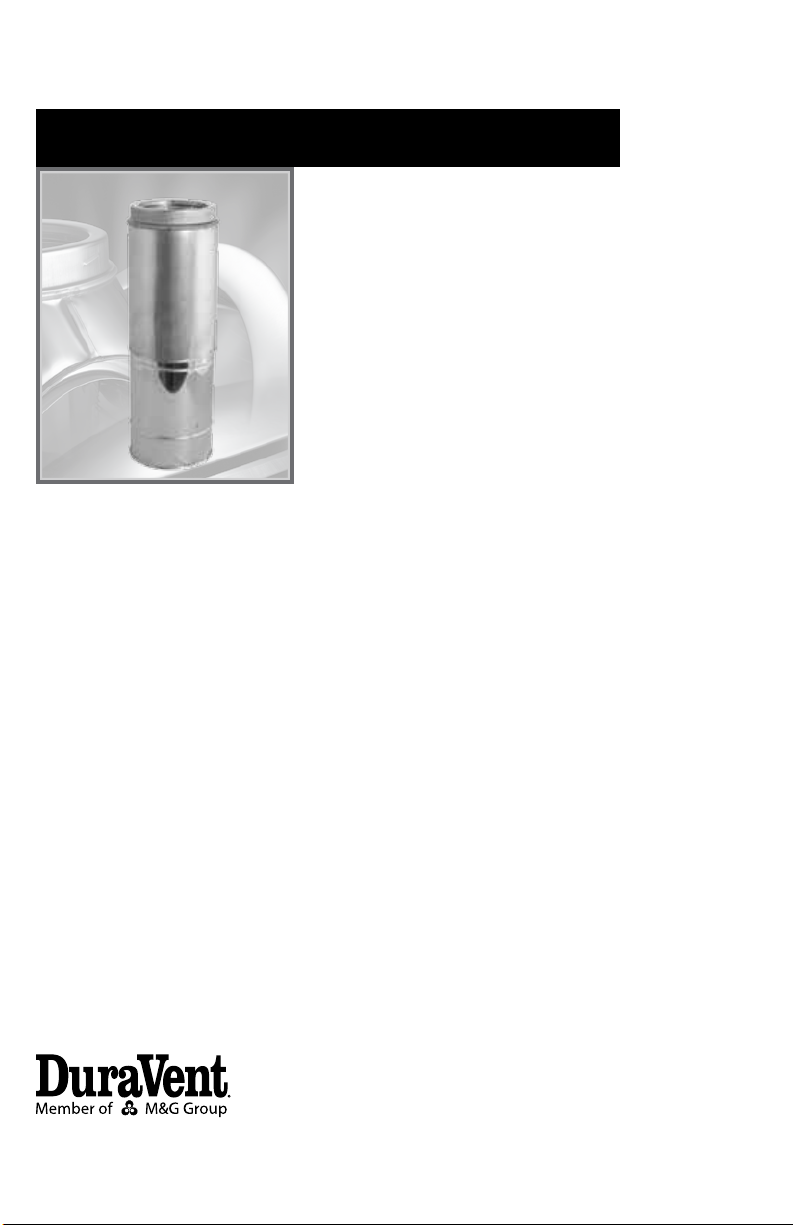
Installation Instructions Supplement
Adjustable Length
Chimney Section
DuraTech
Page 2
A MAJOR CAUSE OF CHIMNEY
RELATED FIRES IS FAILURE TO
MAINTAIN REQUIRED CLEARANCES
(AIR SPACES) TO COMBUSTIBLE
MATERIALS. IT IS OF THE UTMOST
IMPORTANCE THAT THIS CHIMNEY
BE INSTALLED ONLY IN
ACCORDANCE WITH THESE
INSTRUCTIONS.
APPLICATION AND LISTING
A DuraTech Adjustable Length is a listed component of the UL Listed DuraTech Chimney
System (MH7399). Installation of the Adjustable Length must comply with both these
supplementary installation instructions and the
full DuraTech Chimney Installation Instructions
(L150).
INSTALLATION NOTES
Practice good workmanship. Exercise extreme
caution when working on roofs. Be sure to
wear appropriate safety gear and clothing
as needed. You must useonly authorized
DuraTech Chimney parts to maintain a listed
Chimney system (not including the connector
pipe). Do not mix parts or try to match with
other products, or use improvised solutions.
Do not install damaged or modied parts.
Refer to the full DuraTech Chimney Installation
Instructions for further safety details.
WARNING
DuraTech Chimney system is listed with a
2” minimum clearance (air space) to combustibles. Always maintain a minimum of 2”
clearance between chimney pipe and nearby
combustibles. Failure to maintain the minimum
2” clearance to combustibles can result in a
re hazard.
INSTALLATION
The DuraTech Adjustable Length is used
when an exact length of chimney is needed
and standard lengths of chimney are not
sufcient. The Adjustable Length spans from
minimum of 14” to a maximum of 22” and can
be used between any other DuraTech chimney
sections (straight pipe lengths, elbows, tees,
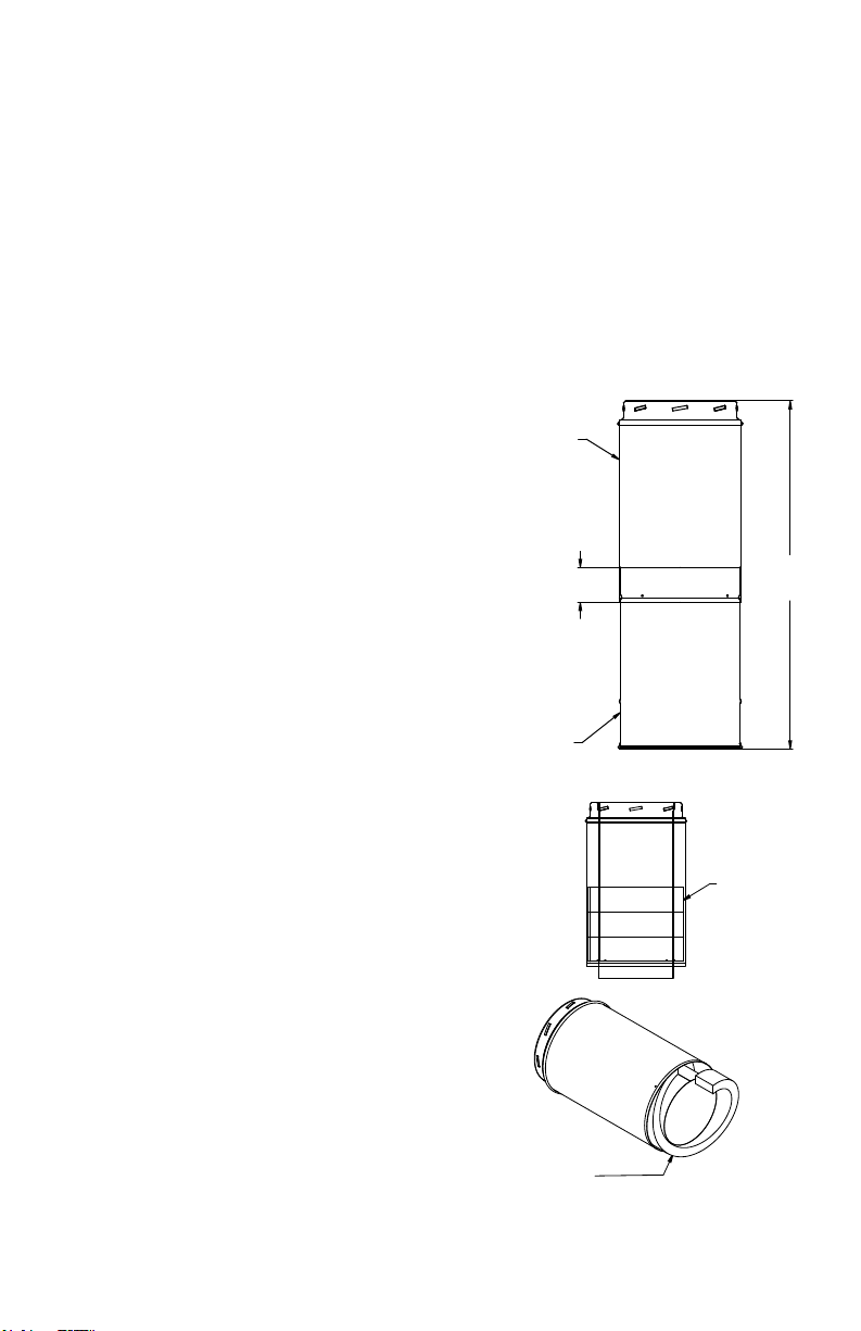
etc.). The Adjustable Length is a telescoping
section of chimney with both male and female
sections (Figure 1). Within the male section
there are 2” wide strips of insulation that can
be removed to allow for a customized length
(Figure 2).
MALE END
SECTION
MIN 2”
OVERLAP
FEMALE END
SECTION
IF NEEDED, ADJUST
LENGTH BY REMOVING
STRIPS OF INSULATION
(SEE TABLE 1).
Figure 1
14” - 22”
2” WIDE
INSULATION
STRIPS
Figure 2
Page 3

1. Determine the length of the Adjustable
Length needed for your installation. The
Adjustable Length can adjust from 14” to 22”.
There will be 1-1/4” lost to the joint between
the Adjustable Length and the next section of
chimney.
2. Remove insulation strips from male end
of pipe, as needed, depending on the length
required for your installation (Figure 2). Be very
careful on how much, if any, insulation is removed from the male section. Refer to Table 1.
Table 1
Required
Total Length
20” - 22”
18” - 20”
16” - 18”
14” - 16”
Insulation
Removed
0 strips
removed
1 strip
removed
2 strips
removed
3 strips
removed
4. Twist lock the Adjustable Length into the
DuraTech chimney system. The Adjustable
Length is not intended to support chimney
either above or below. If the Adjustable Length
is installed in a system with more than 4-ft of
chimney above it, install either an Elbow Strap
or Tee Support immediately above the Adjustable Length to carry the additional weight of
the chimney above. Similarly, if the Adjustable
Length is supporting more than 4-ft of chimney
below it, install an Elbow Strap or Tee Support
immediately below the Adjustable Length to
carry the weight of the chimney below. See
Figure 3.
WALL STRAP OR
TEE SUPPORT
WALL
WARNING: The entire Adjustable Length
must be lled with insulation, without gaps.
The insulation of the female section must
be in contact with the insulation of the
male section. There must be a continuous
section of insulation within the Adjustable
Length. Failure to ensure the insulation is
continuous can result in a re hazard.
3. Slide the two sections of the Adjustable
Length together, compressing the insulation as
needed to achieve the desired length. Important: the outer walls of the two sections must
overlap a minimum of 2” to ensure a proper
connection. When the Adjustable Length is
at the correct length, secure the two sections
together with (4) sheet metal screws provided.
TEE SUPPORT
OR WALL STRAP
Figure 3
5. Complete the DuraTech chimney installation as directed in the full DuraTech Chimney
Installation Instructions (L150).
3
Page 4

M&G DURAVENT WARRANTY
M&G DuraVent, Inc. (“DuraVent”) provides this limited lifetime warranty for all of its products to the original purchaser, with the exception of Ventinox (lifetime),
DuraBlack (ve years) and all Termination Caps (ve years). Subject to the limitations set forth below, DuraVent warrants that its products will be free from
substantial defects in material or manufacturing, if properly installed, maintained and used. This Warranty is non-transferable with the exception of Ventinox
which is transferable from the original homeowner to the buyer of the home for a period of ten (10) years. This warranty does not cover normal wear and tear,
smoke damage or damage caused by chimney res, acts of God, or any product that was: (1) purchased other than from an authorized DuraVent dealer, retailer
or distributor; (2) modied or altered; (3) improperly serviced, inspected or cleaned; or (4) subject to negligence or any use not in accordance with the printed
materials provided with the product as determined by DuraVent. This limited lifetime warranty applies only to parts manufactured by DuraVent.
DuraVent provides the following warranties for its products: One Hundred Percent (100%) of the purchase price or MSRP at time of purchase, whichever is lower,
for 15 years from the date of purchase, and Fifty Percent (50%) thereafter, except for the following limitations: Ventinox liner and components in wood, oil, wood
pellet, and gas installations are warranted at One Hundred Percent (100%) for the lifetime of the original homeowner; Ventinox 316 liner and components for
coal burning installations which are warranted One Hundred Percent (100%) for ten years; all Termination Caps and DuraBlack® are warranted at One Hundred
Percent (100%) for ve years, and at Ten Percent (10%) thereafter.
All warranty obligations of DuraVent shall be limited to repair or replacement of the defective product pursuant to the terms and conditions applicable to each
product line. These remedies shall constitute DuraVent’s sole obligation and sole remedy under this limited warranty. This warranty provides no cash surrender
value. The terms and conditions of this limited lifetime warranty may not be modied, altered or waived by any action, inaction or representation, whether oral
or in writing, except upon the express, written authority of an executive ocer of DuraVent.
VENTI NOX WARRAN TY CONDIT IONS
Liner and Component warranties contained herein are subject to the following conditions: (1) The Liner and Components must be installed according to DV’s
installation instructions; (2) The Liner and Components are used only to line or reline chimneys venting residential appliances for which the liner was intended;
and (3) documented annual inspection of the Liner and Components and maintenance as deemed necessary, beginning one year after the date of installation
and continuing throughout the warranty period, by a Nationally Certied Chimney Sweep or VENTINOX® installer. The Liner and Components warranty is further
subject to compliance with the following requirements throughout the warranty period: The chimney must have a chimney cap and chemical chimney cleaners
must not be used when cleaning the Liner or Components. Plastic-bristle ue cleaning brushes are recommended. Corn, biofuels, driftwood or other wood
containing salt, preservative-treated lumber, plastic and household trash or garbage, or wood pellets containing such materials must not be burned in the
appliance or replace. In case of a chimney re, the chimney must be inspected and approved by a certied Chimney Sweep before reuse. After each annual
inspection, maintenance, and cleaning, the certied Chimney Sweep must ll out and date the appropriate section of the warranty card provided with the
chimney liner.
LIMITATIONS ON INTERNET SALES:
Notwithstanding any other terms or conditions of this limited lifetime warranty, DuraVent provides no warranty for the following specic products if such
products are both: (a) purchased from an Internet seller; and (b) not installed by a qualied professional installer: DuraTech®, DuraPlus HTC®, PelletVent Pro®,
FasnSeal®, and DuraVent’s relining products including DuraLiner®, DuraFlex® 304, DuraFlex® 316, DuraFlex® Pro, DuraFlex® SW, and Ventinox®. For purposes of
this warranty, a trained professional installer is dened as one of the following: licensed contractors with prior chimney installation experience, CSIA Certied
Chimney Sweeps, NFI Certied Specialists, or WET T Certied Professionals.
DuraVent reserves the right to inspect defective product to determine if it qualies for replacement under the terms of this limited lifetime warranty. All warranty
claims must be submitted with proof of purchase. Labor and installation costs are not covered under this warranty. To obtain warranty service contact DuraVent
promptly at DuraVent Warranty Service, 902 Aldridge Rd., Vacaville CA 95688, or call 800-835-4429.
WHERE LAWFUL, DuraVent DISCLAIMS ALL OTHER WARRANTIES, INCLUDING BUT NOT LIMITED TO IMPLIED WARRANTIES OF MERCHANTABILITY AND FITNESS
FOR A PARTICULAR PURPOSE. IN NO EVENT WILL D uraVent BE LIABLE FOR INCIDENTAL, CONSEQUENTIAL, PUNITIVE OR SPECIAL DAMAGES OR DIRECT OR
INDIRECT LOSS OF ANY KIND, INCLUDING BUT NOT LIMITED TO PROPERTY DAMAGE AND PERSONAL INJURY. DuraVent’S ENTIRE LIABILITY IS LIMITED TO THE
PURCHASE PRICE OF THIS PRODUCT. SOME STATES DO NOT ALLOW LIMITATIONS ON IMPLIED WARRANTIES, OR THE EXCLUSION OR LIMITATION OF INCIDENTAL
OR CONSEQUENTIAL DAMAGES, SO THE ABOVE LIMITATIONS AND EXCLUSIONS MAY NOT APPLY TO YOU. THIS LIMITED WARRANTY GIVES YOU SPECIFIC LEGAL
RIGHTS, AND YOU MAY ALSO HAVE OTHER RIGHTS THAT VARY FROM STATE TO STATE .
For the most up-to-date installation instructions, see www. duravent.com
REV 7.20.2010
M&G DuraVent, Inc. PO Box 1510 Vacaville CA 95696-1510
Manufactured in Vacaville CA and Albany NY
Customer Service Support 800-835-4429 707-446-4740 FAX www.duravent.com
DuraTech is a registered trademark of the M&G DuraVent, Inc.
All rights reserved. Made in the USA. M&G DuraVent is a member of M&G Group. ©2011
L156 03/2011
 Loading...