

Page 1
Installation Instructions
All-Fuel Chimney System
10” to 24” diameter
DuraTech
Page 2

A MAJOR CAUSE OF VENT RELATED FIRES IS FAILURE
TO MAINTAIN REQUIRED CLEARANCES (AIR SPACES) TO
COMBUSTIBLE MATERIALS. IT IS OF THE UTMOST IMPORTANCE
THAT DURATECH BE INSTALLED ONLY IN ACCORDANCE WITH
THESE INSTRUCTIONS.
IMPORTANT:
Read through all of these instructions
before beginning your installation. Failure
to install this product as described in these
instructions will void the manufacturer’s
warranty, may create a re or other safety
hazard, and may affect your homeowner’s
insurance and safety listing of your
appliance.
Keep these instructions for future
reference.
Dear Customer, Installer, or End User:
We welcome any comments regarding matters
pertaining to our DuraVent products.
We welcome any ideas, input or complaints
and I’ll make sure that someone responds
directly back to you.
Send your emails to:
[email protected]
If you are searching for tech support or product
information, please phone us at 800-835-4429.
Or email us at:
[email protected]
LISTED
MH7399
Page 3

ALL FU EL CHI MNEY S YSTEM F OR 10" 24" DI AMETE R
For the most up-to-date installation instructions, see www.duravent.com
CONTENTS
Clearances, Permits, Equipment Needed, Chimney Applications, Notes . . 4
Chimney Diameter, Height & Placement, Enclosure Requirements. . . . . . . 5
Appliance Recommendations. . . . . . . . . . . . . . . . . . . . . . . . . . . . . . . . . . . . . . 6
Ceiling Support . . . . . . . . . . . . . . . . . . . . . . . . . . . . . . . . . . . . . . . . . . . . . . . . . 7
Elbow Offset Installation . . . . . . . . . . . . . . . . . . . . . . . . . . . . . . . . . . . . . . . . . . . . . 12
Tee Supported Installations . . . . . . . . . . . . . . . . . . . . . . . . . . . . . . . . . . . . . . . . . . 14
Masonry Fireplace Installations . . . . . . . . . . . . . . . . . . . . . . . . . . . . . . . . . . . . . . . 18
Chimney Maintenance . . . . . . . . . . . . . . . . . . . . . . . . . . . . . . . . . . . . . . . . . . . . 21
Typical Installations . . . . . . . . . . . . . . . . . . . . . . . . . . . . . . . . . . . . . . . . . . . . 23
Warranty. . . . . . . . . . . . . . . . . . . . . . . . . . . . . . . . . . . . . . . . . . . . . . . . . . . . . . 24
DuraTech
3
Page 4

CLEARANCES
Always allow at least a 2-inch clearance
between DuraTech Chimney Pipe and any
combustible materials. Never ll any required
clearance space with insulation or any other
materials. Combustible materials include
lumber, plywood, sheetrock, plaster and lath,
furniture, curtains, electrical wiring and building
insulation. Keep single wall stovepipe at least
18 inches away from combustible materials,
unless a clearance reduction system that is
acceptable to the authority having jurisdiction
is used, or the appliance to be installed is
listed and the instructions specify a different
clearance.
PERMITS
Contact your local Building Ofcial or Fire
Ofcial regarding permits, restrictions, and
installation inspections in your area.
DURATECH CHIMNEY
APPLICATIONS
DuraTech Chimney 1700°F (10”-24” diameter)
is a complete chimney system tested and
listed to UL Test Procedure 103, and ULC
S604. In the United States, DuraTech
Chimney can be used with wood replaces,
furnaces, boilers, water heaters, ranges, or
other residential-type appliances fueled by oil,
gas, coal, or wood, that have been tested and
listed for use with a UL103 chimney system.
In Canada, DuraTech can be used with oil &
gas red appliances listed for use with a Type
A Chimney, in accordance with ULC S604.
DuraTech Chimney 1700°F is available in
10” through 24” diameters. Do not use with
forced draft, positive-pressure appliances.
The DuraTech Chimney system is designed
to extend vertically with a maximum of one
(1) offset (two elbows total) of up to 30° from
4
vertical. DuraTech Chimney is listed under UL
Re-examination Service Number MH7399.
EQUIPMENT & MATERIALS
Drill / Driver
Hammer
Caulking Gun
Plumb Bob
Screwdrivers (Phillips & Standard)
Tin Snips
Saber or Keyhole Saw
Level
Dependable Ladder
Tape Measure
Proper Gloves and Shoes
Eye Protection
Materials You May Need:
Non-hardening Waterproof Sealant
8 Penny Nails
#8, 2-1/2” & 1-1/2” Wood Screws
Roong Nails
600OF RTV Silicone Sealant
INSTALLATION NOTES
Proper planning for your DuraTech Chimney
installation will result in greater safety,
efciency, and convenience, as well as
saving time and money. You must use
only authorized DuraTech Chimney parts
to maintain a listed Chimney system (not
including the connector pipe). Do not mix parts
or try to match with other products, or use
improvised solutions. Do not install damaged
or modied parts. Each solid-fuel appliance
must be vented with its own chimney. Table
1 lists the authorized DuraTech Chimney
components. Practice good workmanship.
Sloppy work could jeopardize your chimney’s
safety. Keep electrical wiring and insulation
away from all chimneys and stovepipes. If you
have any questions, be sure to contact either
your dealer or DuraVent directly.
Page 5
CHIMNEY DIAMETER
Follow the appliance manufacturer’s
instructions to determine chimney diameter
and clearances between combustible materials
and your heating appliance. Never choose a
chimney with an inside diameter smaller than
your appliance’s outlet. If you are connecting
to a masonry replace, refer to Table 4, for
proper sizing. To calculate the chimney’s
outside diameter, add 2 inches to the inside
diameter.
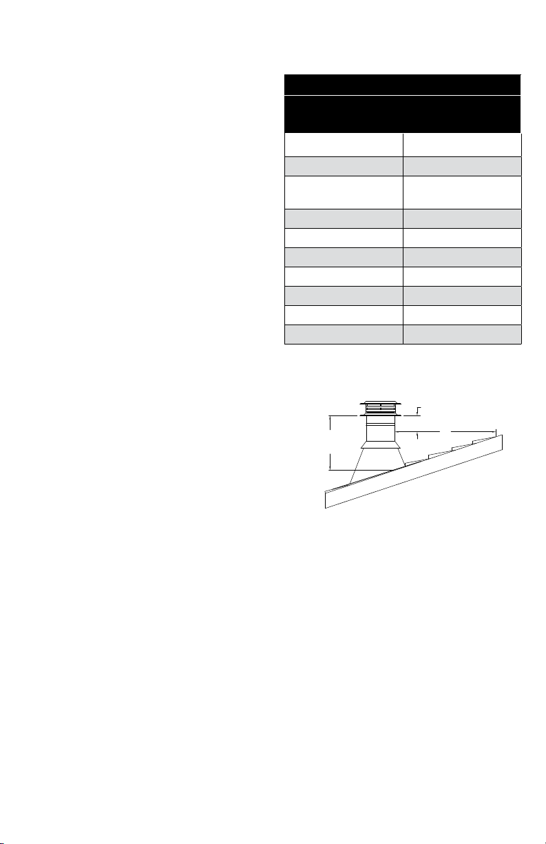
CHIMNEY HEIGHT
The National Fire Protection Association
Standard #211 states: “Chimneys shall
extend at least three feet above the highest
point where it passes through the roof of a
building, and at least two feet higher than
any portion of a building within ten feet.” (Fig
1) 10”-16" diameter DuraTech Chimney may
be installed up to 40 feet high when using a
Support Box, and up to 30 feet high when
using a Tee Support. DuraTech in 18”-24”
diameters is intended to be mounted directly
to an appliance or masonry replace, and is
limited in height by the allowable weight of the
supporting surface, up to a maximum of 60-ft.
If the chimney extends more than 4 feet above
the roof, an Extended Roof Bracket must be
used. Due to the overlap of the joints, subtract
3/4” from each Chimney Section’s height to
calculate installed height.
Table 1
DuraTech Cimney Components
12”, 18”, 24” & 36” S ECTIONS R OUND CEIL ING SUPPO RT BOX
FIRES TOP RADIATION SHIELD EXTE NDED ROOF BRACKET
ELBOW AT TIC
INSUL AT ION SHIEL D ADJUS TA BLE ROOF F LASHING
TEE WIT H T EE CAP WALL THIMB LE
ELBOW STRAP CHASE TOP FLASHING
TEE SU PPORT FINIS HING COLL AR
BRACK ET WA LL STRAP FLAT ROOF FLASHIN G
CHIMN EY CAP ROOF RA DIATION SHIE LDS
ANCHO R PLATE STORM CO LLAR
3 FT.
MIN.
ABOVE
ROOF
TRIM CO LLARS FO R ROUND
SUPPO RT BOXES
2 FT. MIN. ABOVE
HIGHEST POINT OF
ROOF WITHIN 10 FT.
10'
Figure 1
CHIMNEY PLACEMENT
When deciding the location of your chimney,
try to avoid modications to roof beams and
other structural components of the building.
CHIMNEY ENCLOSURE
REQUIREMENTS
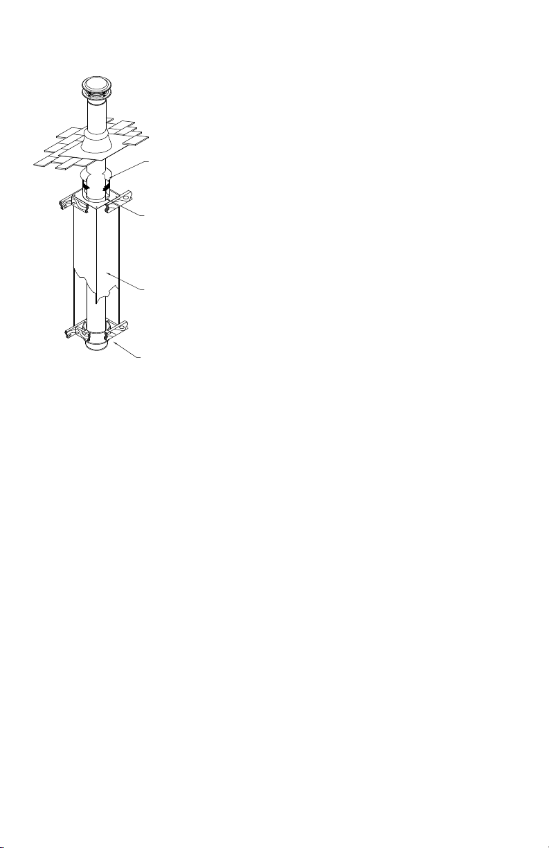
Through Rooms: Interior chimneys shall
be enclosed where they extend through
closets, storage areas, occupied spaces, or
anyplace where the surface of the chimney
could be contacted by persons or combustible
materials. The space between the outer wall
of the chimney and the enclosure shall be at
5
Page 6
condensation and creosote formation, and
enhance draft. Include an access door by the
Tee Cap for chimney cleaning (Refer to Fig
18).
ATTIC
ATTIC
SPACE
OCCUPIED
SECOND
FLOOR
FIRST
FLOOR
INSULATION
SHIELD
FIRESTOP
RADIATION
SHIELD
(INSIDE)
ENCLOSURE MUST HAVE 2
INCHES OF CLEARANCE
BETWEEN CHIMNEY AND WALL
SUPPORT BOX
Figure 2
least 2 inches (Fig 2).
Multi-Story: Consult local building code
ofcials for requirements in your area. The
National Fire Protection Association Standard
#211 states: “Factory-built chimneys that
pass through oors of buildings requiring
the protection of vertical openings shall be
enclosed with approved walls having a re
resistance rating of not less than one hour
when such chimneys are located in a building
less than 4 stories in height, and not less than
2 hours when such chimneys are located in
a building more than 4 stories in height.” In
Canada, except in single-family and two-family
dwellings, chimneys which extend through
another storey must have an enclosure with a
re resistance rating equal to or greater than
that of the oor or roof assembly through which
they pass.
Cold Climates: In cold climates, chimneys
mounted on an outside wall should be
enclosed in a chase. Exterior chases reduce
6
APPLIANCE RECOMMENDATIONS
Follow the appliance manufacturer’s
instructions. The requirements stated
below pertain to all appliances installed with
DuraTech Chimney systems.
Choice: Choose an appliance that is listed by
a recognized testing laboratory, is appropriate
for your needs, and is not larger than required.
Installation: Once the chimney system is in
place, install the appliance and stovepipe
(if applicable) as described in the appliance
manufacturer’s instructions. Be sure to
maintain all required clearances.
Flues: Connect only one solid fuel appliance
per chimney.
Operation: Follow the appliance
manufacturer’s instructions and safety manual
for maximum efciency and safety. Overring
can damage the appliance, stovepipe and
chimney, and can void your warrenties.
Fuels: Do not burn driftwood, plastic, or
chemically treated wood such as railroad
ties. They are corrosive to your appliance
and chimney system. Follow the appliance
manufacturer’s instructions and safety manual
in regards to fuels. Not all appliances are
equipped to burn coal. Coal with a low sulfur
content will reduce the possibility of corrosion.
STEP-BY-STEP DIRECTIONS
There are three general types of DuraTech
Chimney installations:
1. Ceiling-supported.
2. Tee-supported (through-the-wall)
3. Masonry Fireplace
Review the step-by-step directions before
beginning your installation.
Page 7
CEILING SUPPORT
Ceiling supported systems are available for
diameters 10”-16".
1. Place Appliance: Position the appliance
according to the manufacturer’s instructions.
The ue outlet collar should be placed
between the rafters or joists above, if possible.
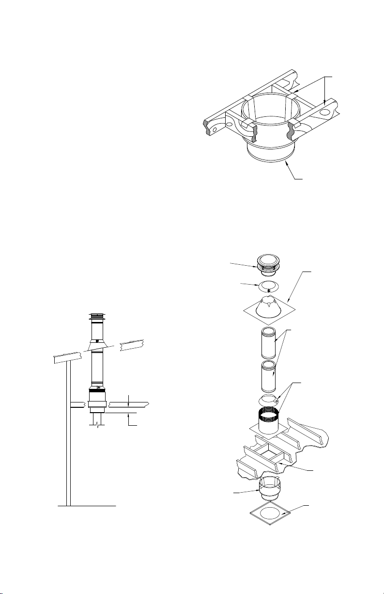
2. Frame Support Opening: Drop a plumb
bob to the center of the appliance’s ue outlet
and mark this center point on the ceiling. Refer
to Table 2 for specic framing and clearance
dimensions. Mark appropriate cutting lines
around the center point. Cut a square hole in
the ceiling for the Support Box. Frame a level,
square opening centered over the hole which
you have cut. (Figures 3 and 4).
CHIMNEY CAP
STORM COLLAR
Figure 4
3-INCH MINIMUM
REQUIRED BELOW
FINISHED CEILING
ADJUSTABLE
FLASHING
CHIMNEY
SECTIONS
JOISTS &
FRAMING
CONNECTOR PIPE
GOING TO
APPLIANCE.
ALWAYS MAINTAIN A
MINIMUM OF 18 INCHES
CLEARANCE TO
COMBUSTIBLES FOR
SINGLE-WALL STOVEPIPE
MINIMUM OF 3
INCHES BELOW
FINISHED CEILING
ROUND
SUPPORT BOX
Figure 3
ATTIC
INSULATION
SHIELD
FRAMED
OPENING
ROUND TRIM
COLLAR
7
Page 8
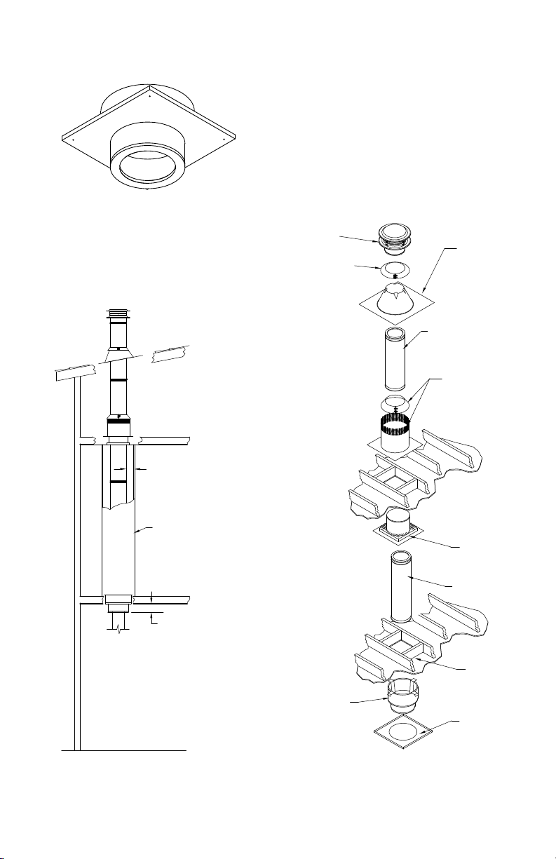
ROUND SUPPORT
BOX WITH SQUARE
TRIM COLLAR
3. Install Support: For installation into a at
ceiling, you need to use the Round Support
Box. The Round Ceiling Support Box has
the option of a square or round Trim Collar
available (Fig 5). The Support Box must
extend at least 3 inches below the nished
ceiling. (do not install beyond 4-1/2” below
nished ceiling or the trim collar will not cover
Figure 5
2 INCH MINIMUM
CLEARANCE TO
INSIDE OF ENCLOSURE
FRAMED
ENCLOSURE
MINIMUM OF 3 INCHES
BELOW FINSHED CEILING
CAP
STORM
COLLAR
CHIMNEY
SECTIONS
ATTIC
INSULATION
SHIELD
ADJUSTABLE
FLASHING
FIRESTOP
RADIATION
SHIELD
CHIMNEY
SECTION
CONNECTOR PIPE
TO APPLIANCE.
MAINTAIN AT
LEAST 18 INCH
FOR SINGLE WALL
STOVEPIPE
ROUND
SUPPORT BOX
FRAMED
OPENING
SQUARE
TRIM
Figure 6
8
Page 9
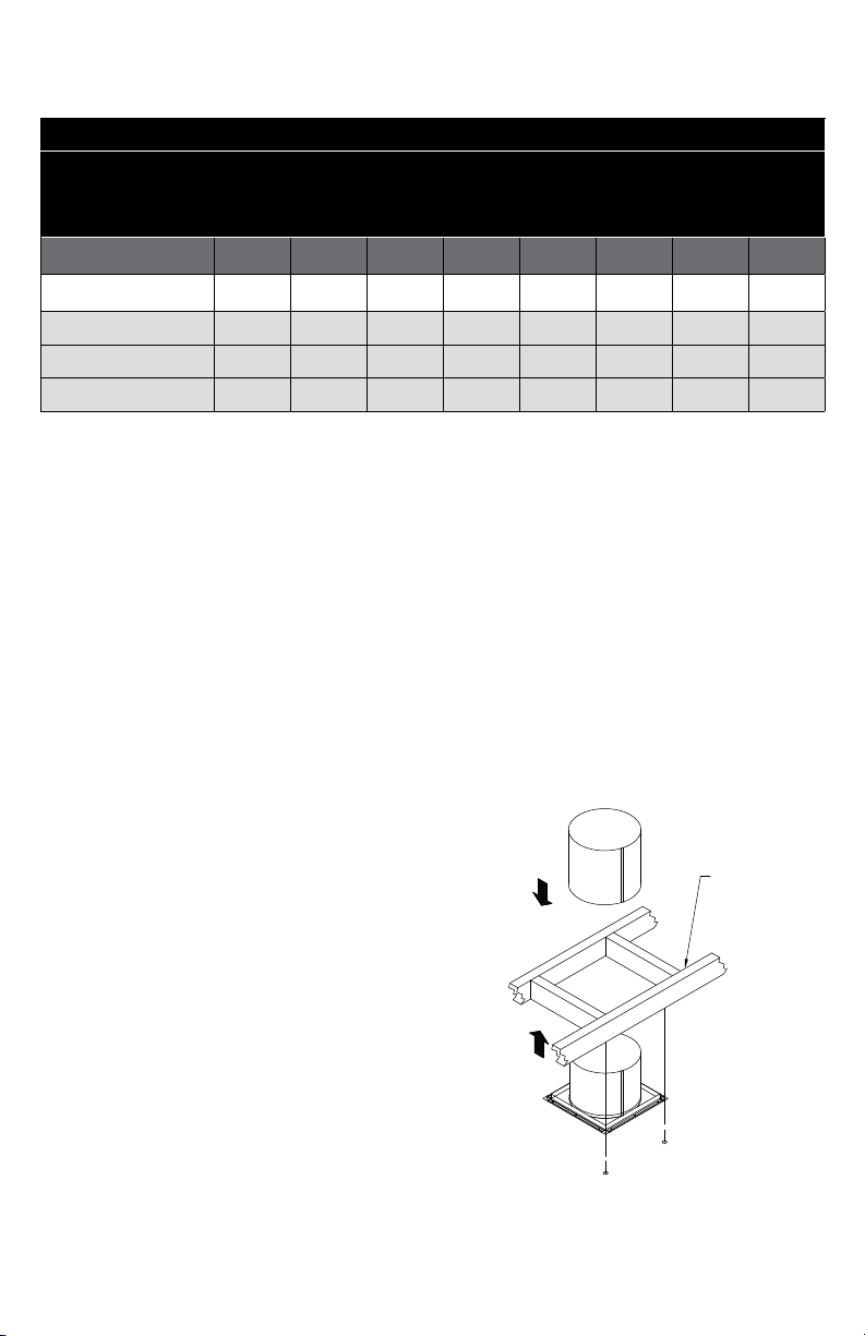
Table 2
Inside Square Framing Dimensions
(X" x X")
Chimney Diameter 10" 12" 14" 16" 18" 20" 22" 24"
CEILI NG SUPPOR T BOX
WALL THIMB LE
FIRESTOP RADI ATION SH IELD
ATTIC IN SULATION SHI ELD
16 1/4" 18 1/4" 20 1/4" 22-1/4" na na na na
16" 18" 20" 22" na na na na
16" 18" 20" 22" 24 1/4" 26 1/4" 28 1/4" 30 1/4"
16 1/4" 18 1/4" 20 1/4" 22 1/4" 24 1/4" 26 1/4" 28 1/4" 30 1/4"
properly). Level the Support Box and secure
it to the framing using at least three 8-penny
nails per side (min. of 12 total). Wrap the
straps of the Support Box around the framing
members (Fig 4), and secure with (2) 8-penny
nails per side (eight nails total). Alternatively,
you may use 1-1/2” #8 wood screws (min. of
12 total for the Support Box, and 8 total for
the straps), instead of nails. Next, secure
the round or square Trim Collar to the ceiling/
framing members using (4) 1” long, roundhead wood screws.
4. Frame Openings: Frame openings in
each ceiling or oor above the Support Box
(Fig 6). These openings are to hold the
Firestop Radiation Shield and Attic Insulation
Shield. Locate each opening by dropping a
plumb bob to the four corners of the opening
below. Maintain the minimum clearances and
dimensions as specied in Table 2. If Elbows
must be used to avoid an obstruction, refer to
the Offset Elbow Installation section.
5. Cut Roof Opening: Cut an opening in the
roof directly above the opening below, and
at least 4 inches larger than the chimney’s
outside diameter to provide at least a
2-inch clearance all around the chimney.
The chimney must be centered within this
opening and maintain the 2-inch clearance to
combustibles.
6. Install Firestop Radiation Shield: A Firestop
Radiation Shield is required in multistory
installations at each oor penetration above
that where the Support Box is located.
Example: in a multistory home where the
appliance is on the ground oor (Support
Box is in the 1st oor ceiling), you would
need a Firestop Radiation Shield at the 2nd
oor ceiling, and at the 3rd oor ceiling, etc.,
FRAMING
FIRESTOP
RADIATION
SHIELD
Figure 7
9
Page 10
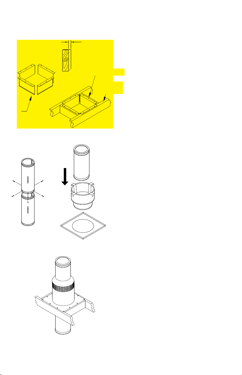
ROOF
RADIATION
SHIELDS
Figure 8
INSTALL ROOF RADIATION
SHIELDS WITH A 1/2"
CLEARANCE FROM ROOF
JOIST FACE.
NAILS OR SCREWS
ROOF
JOISTS
including where the chimney penetrates into
the attic. Figure 6 shows a typical 2-story
installation with an attic.
Note: a Firestop Radiation Shield is not
installed where the chimney penetrates
through the roof. Instead, you will need to
install Roof Radiation Shields (required for
18”-24” diameters only - see Step 7) around
the roof joist members. The Firestop Radiation
Shield is installed on the underside of the
ceiling/oor framing, with the cylindrical “tube”
portion of the shield pointing upward (Fig 7).
Use a minimum of either (1) 8 penny nail or (1)
1-1/4” wood screws per corner. Refer to Table
2 for framing requirements.
10
Figure 9
Figure 10
ATTIC
INSULATION
SHIELD
CHIMNEY
SECTION
SITS INSIDE
SUPPORT
BOX
SUPPORT
BOX WITH
SQUARE
TRIM
7. Install Roof Radiation Shields: Roof
Radiation Shields are required for 18”-24”
diameter chimney installations. Roof Radiation
Shields provide protection for roof framing
members.
Note: Combustible materials will still need to
be a minimum of 2” away from the chimney.
Roof Radiation Shields must be installed with
their face 1/2” off of the roof framing joists (Fig
8). Depending upon the pitch of your roof,
trim the Roof Radiation Shields with tin snips
so they provide complete coverage of the
roof framing exposed to the chimney. Secure
the Roof Radiation Shields to the top of the
framing members using at least (3) nails or
screws for each shield (Fig 8).
8. Assemble Chimney Sections: Lower the
female end of the rst Chimney Section in the
Support Box (Fig 9). Sheet metal screws are
not required between the rst Chimney Section
and the Support Box. For each additional
Chimney Section use the (6) Sheet metal
screws provided to make a secure connection
between the chimney sections (Fig 9). Do not
penetrate the inner liner of the chimney.
Page 11

9. Install Attic Insulation Shield: Install
the Attic Insulation Shield where the chimney
passes into an attic. It’s purpose is to prevent
debris and building insulation from getting too
close to the chimney (Fig 10). An installed
Attic Insulation Shield is 15 inches high. In
attic areas where this shield cannot t, you
must enclose the attic portion of the chimney
in a framed enclosure. If the chimney is fully
enclosed through the attic, an Attic Insulation
Shield is not required. Where the chimney
passes into the attic, install the Attic Insulation
Shield as follows:
a. If the Firestop Radiation Shield extends
above the attic oor, no modications are
necessary. The Firestop Radiation Shield will
t inside the Attic Insulation Shield.
b. Assemble Chimney Sections until at least
18 inches of chimney extends above the
Firestop Radiation Shield.
c. Slip the Attic Insulation Shield over the
Chimney and Firestop Radiation Shield until
the base sits squarely on the framed opening
(Fig 6 & 10).
d. Secure the Attic Insulation Shield to the
top of the framed opening using at least (3)
8-penny nails or (3) #8, 1-1/2” wood screws
per side (Fig 10).
e. Wrap the Collar of the Attic Insulation
Shield around the chimney and fasten it
loosely. Slide the Collar down to meet the Attic
Insulation Shield. Tighten the bolts to secure
the Collar in place (Fig 11).
10. Attach Flashing: In new construction,
assemble the Chimney Sections to a point
above the roof, then slip the Flashing over
the chimney. On an existing roof, center
and install the Flashing before extending the
chimney above the roof. Allow space to permit
sliding the next Chimney Section up through
the Flashing. Always ensure the chimney
Figure 11
remains vertical (use a level), and that at least
a 2-inch clearance to combustible materials is
maintained all around. Install the upper edge
of the Flashing under the roong. Nail to the
roof along the upper edge and down each
side with 1-inch roong nails. Do not nail the
lower edge of the Flashing (Fig 12). Be sure
to follow local building practices, as needed.
Seal all nail heads with a non-hardening
waterproof sealant. On at or tarred and
graveled roofs, nail and seal the Flat Roof
Flashing to the roof on all sides with roong
compound. Do not put screws through the
Flashing into the Chimney Pipe.
11. Finish Top: Apply a non-hardening
waterproof sealant around the chimney at the
point where the Storm Collar will meet the
chimney just above the Flashing, and also
along the vertical seam of the chimney pipe,
where it is exposed to the weather (Figures
12 and 13). Slide the Storm Collar down
over the chimney to the top of the Flashing.
Tighten the bolts of the Storm Collar and seal
the Storm Collar against the sealant. After
installing sufcient Chimney Sections to meet
the height requirement as shown in Figure
1, attach the Chimney Cap onto the top of
11
Page 12
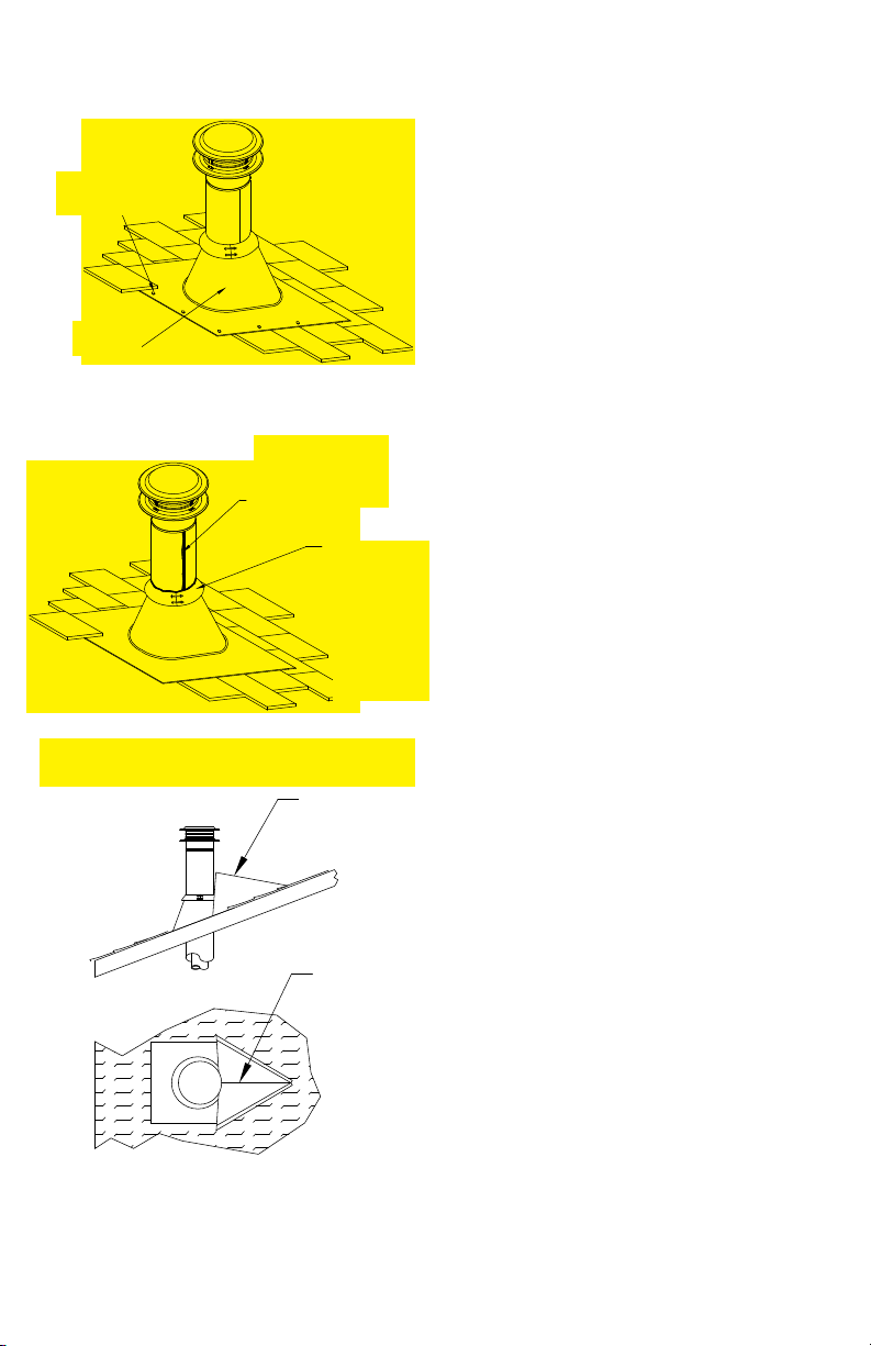
ROOFING
FASTENERS
ADJUSTABLE
FLASHING
Figure 12
Figure 13
SEAL EXPOSED SEAM
WITH
NON-HARDENING HIGHTEMP
SILICONE SEALANT
PUSH COLLAR
DOWN
TO FLASHING AND
SEAL WITH
NONHARDENING
HIGHTEMP
SILICONE
SEALANT
SNOW
SPLITTER
the chimney by setting the female end of the
Cap onto the male end of the last chimney
section. Secure the Cap by using (6) sheet
metal screws provided. Do not push down
from the top portion of the cap as this may
damage the cap. Push from the lower section
of the Cap if needed. The Chimney Cap can
be removed for chimney cleaning as described
in the Chimney Maintenance section of the
instructions. Use an Extended Roof Bracket if
the chimney extends more than 4 feet above
the roof (Figures 16 & 17 in the Extended
Roof Bracket section).
If you are located in heavy snow country, a
“snow splitter” should be used to protect the
chimney by routing snow around the pipe.
DuraVent offers a Snow Splitter or one can
be fabricated locally from heavy gauge sheet
metal (Fig 14).
12. Enclosures: Enclose chimneys where
they pass through occupied spaces, including
closets. Always maintain at least a 2 inch
clearance between the chimney and any
combustible materials. Interior enclosures
may be constructed with standard framing
and sheathed with sheetrock or plywood. Use
Wall Straps at least every 4 feet to maintain a
minimum of 2 inches of air space between the
chimney and combustible materials.
12
Figure 14
SNOW
SPLITTER
TOP VIEW
OFFSET ELBOW INSTALLATION
DuraTech allows for the use of one pair of
30° Elbows (measured from the vertical) for
chimney sizes 10” - 24”. A 30° Elbow is the
largest that can be used in an offset from
vertical. A 30° Elbow may not be combined
with another elbow to make a steeper offset
(e.g. two 30° Elbows are not allowed to be put
together to form a 60° elbow from vertical).
Avoid Elbows if possible, since a totally vertical
chimney is more efcient. When Elbows
Page 13

are necessary to avoid obstructions such
as rafters, ridgepoles, or joists, you are only
allowed to use 1 pair of Elbows in any one
chimney system.
1. Attach Elbows: Attach Elbow to Chimney
Section or other Elbow by mating the male
and female ends with each other and using
the (6) sheet metal screws provided. Attach
one Elbow to the Chimney Section below,
and align it for the offset. Refer to Table 3 to
determine the required offset length and attach
an appropriate length (or lengths) of Chimney
Section(s) above the Elbow. For each
Chimney Section in the offset, an Elbow Strap
must be used to support the weight of that pipe
section. No more than half of the total chimney
run can be between the elbows (inclined); this
is to ensure the chimney drafts properly (e.g. if
the total chimney run is 20-ft, no more than 10ft is allowed to be between the elbows). Attach
the second Elbow above the Chimney Section
to complete the offset (Fig 15).
2. Secure Offset: Place the Elbow Strap’s
band around the angled portion of the top
Elbow, then tighten the nut and bolt until the
clamp is rm. Wrap the Elbow Strap end over
an adjacent joist or rafter and secure it with at
least two 8-penny nails or #8, 1-1/2” screws.
Do not add more Chimney Sections until
the Elbows are supported. Be sure that the
chimney remains vertical (Fig 15).
EXTENDED ROOF BRACKET
INSTALLATION
If the chimney extends more than 4 feet
above the rooine, an Extended Roof Bracket
must be installed at every 4-foot increment of
chimney height above the rooine, leaving no
more than 4 feet of chimney extending above
the last pipe bracket.
T Table 3
Elbow Offset Chart
ELBOW
ANGLE FROM
VERTICAL
30 ' 0" 6 5/8" 25 1/2"
30 ' 12" 12 7/16" 35 1/2"
30 ' 18" 15 7/16" 40 3/4"
30 ' 24" 18 7/16" 45 15/16"
30 ' 36" 24 1/2" 56 1/4"
ELBOW STRAP
CHIMNEY
LENGTH
BETWEEN
ELBOWS
OFFSET
(INCHES)
OFFSET
INCHES
ELBOW
FRAMING
MEMBER
RISE
(INCHES)
RISE INCHES
CHIMNEY
SECTION
Figure 15
13
Page 14
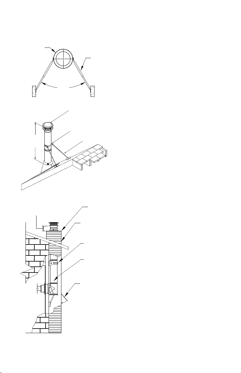
EXTENDED ROOF BRACKET ASSEMBLY
PIPE BAND
AROUND
CHIMNEY
SECTION
USE EXTENDED
ROOF BRACKET IF
MORE THAN 4 FT.
MINIMUM 6 INCHES
CLEARANCE BETWEEN
CAP AND CHASE TOP
CONNECTOR
PIPE TO
APPLIANCE
14
60°
Figure 16
Figure 17
Figure 18
CHIMNEY
CAP
EXTENDED
ROOF BRACKET
ADJUSTABLE
LEGS
FRAMED
EXTERIOR
ENCLOSURE
WALL
STRAP
TYPICAL THRU-THEWALL TEE
SUPPORTED
INSTALLATION
ACCESS
DOOR FOR
CLEANING
ADJUSTIBLE
LEGS ADJUST
FROM 67 TO
114
INCHES
CHASE TOP
FLASHING
The Extended Roof Bracket consists of the
Pipe Band, the Adjustable Legs, and the Roof
Brackets.
1. Mount Pipe Band: Slip the Pipe Band
around the chimney and secure by tightening
the nut and bolt.
2. Attach the Legs: The Adjustable Legs
of the assembly will adjust from 67” to 114”.
Secure one end of the Legs to the Pipe Band
using the nuts and bolts included (1 per Leg).
Position the Adjustable Legs so they form
approximately a 60° angle with the chimney,
and with each other (Figures 16 and 17). Be
sure that there is at least 3” of overlap between
the top and bottom halves of the Adjustable
Leg to ensure a secure t. In order to secure
Legs in proper position, there is a hole
provided in the outer leg where the outer and
inner halves overlap. Use a 1/4” drill bit to drill
through the inner leg at that location. Use the
nut & bolt provided to pin the Adjustible Legs
in position.
3. Install Roof Brackets: Mount the two
Roof Brackets where each of the Adjustable
Legs meets the roof, using 4 roong nails per
bracket. Seal the nail heads carefully with a
non-hardening, waterproof sealant. Attach the
bottom end of the Adjustable Legs to the Roof
Brackets using the nuts & bolts provided.
TEE-SUPPORTED INSTALLATIONS
Tee-Supported installations are used when
passing through a wall to an outside chimney.
Tee-Supported installations are available for
DuraTech chimney 10” through 16" diameters.
The Tee Support can hold a maximum of 30
feet of DuraTech Chimney. The required parts
and general conguration are as shown in
Figures 18 and 19.
Page 15
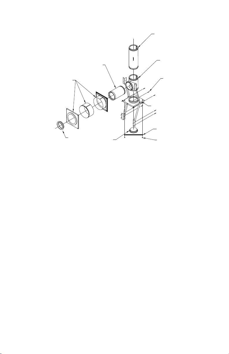
CHIMNEY
SECTION
TEE BRANCH
(MUST PENETRATE
A MINIMUM OF 6
INCHES INTO
ROOM)
WALL THIMBLE
ASSEMBLY
FINISHING
COLLAR
TEE CAP
Figure 19
1. Place Appliance: Position the appliance
according to the manufacturer’s instructions. It
is a good idea to try to position the appliance
so it will allow the chimney to line up centered
between studs.
2. Locate, Cut & Frame Opening:
Determine the location where the chimney will
pass through the wall. The chimney should
pass through the wall, centered between
two studs. The height of the penetration
can be determined by positioning sections
of connector pipe until you have the
desired conguration (refer to the appliance
manufacturer’s installation instructions for
restrictions on connector pipe). Cut and frame
an opening in the inner and outer walls at this
location. Refer to Table 2 for the appropriate
framing dimensions.
3. Install Wall Thimble: The Wall Thimble is a
three piece unit which includes the cover plate,
sleeve extension, and the back portion with
UP
CHIMNEY TEE
1/4"X2" LAG
SCREWS (3
REQUIRED)
TEE CAP
RETAINING BAR
BOLTS FOR
RETAINING BAR
shield. On the outside wall, install the back
portion of the Wall Thimble. Center the back
portion of the Wall Thimble (with shield inside
wall) in the framed opening of the outside wall.
Be sure to seal the ange of the Wall Thimble
around the wall by using a non-hardening
waterproof sealant. Attach the back portion
of the Wall Thimble to the outside wall using
at least (4) 8-penny nails or (4) 1-1/2” wood
screws (Fig 20). Depending on the thickness
of your wall, you will need to adjust the shield
extension to insure that you have a continuous
shield throughout the wall penetration.
Adjustments can be made by sliding the
extension in or out of the back portion of the
shield. Verify that the shield extension reaches
the front cover plate when the cover plate is
in position. Do not install cover plate at this
time. When the shield extension is in position,
secure it to the back portion of the shield using
(4) sheet metal screws (Fig 20).
4. Install Tee Support: Install the Tee
Support on the outside wall. Position Tee
15
Page 16
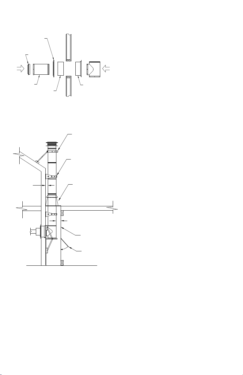
WALL THIMBLE
COVER PLATE
TEE
BRANCH
(MUST
EXTEND AT
LEAST 6
INCHES INTO
ROOM)
2 INCHES
MINIMUM
FINISHING
COLLAR
EXTENSION
INSIDE OUTSIDE
SHIELD
Figure 20
Figure 21
EXTENDED
ROOF SUPPORT
BRACKET
WALL STRAP
FLASHING
2 INCHES
MINIMUM
FRAMED
ENCLOSURE
ACCESS DOOR
FOR CLEANING
CHIMNEY
TEE
BACK OF
WALL
THIMBLE
(SECURE WITH
4 NAILS OR 4
SCREWS)
Support so that the chimney Tee will be
centered inside the Wall Thimble (Figs 19 &
20). Important: Verify that Tee Support is level,
then secure Tee Support to outside wall using
(3) 1/4”x 2” long lag screws for the support
base, and (8) #8, 2-1/2” wood screws for the
brackets (2 screws per bracket). Be sure to
keep the Tee Support level.
5. Install Chimney Tee and Branch:
Attach the Chimney Branch to the Tee. The
Chimney Branch is 12” or 18” Chimney Section
(depending on your wall thickness) positioned
horizontally used to pass through the wall.
Important: The Chimney section used to
penetrate through the wall must extend at
least 6” into the room. Secure the Chimney
Branch to the Tee by using the (6) sheet metal
screws provided. It is very improtant that a
good connection is made between the Branch
and the Tee. (Fig 20 & 21) Install the Tee Cap
in the bottom of the Tee, on the underside of
the Tee Support Bracket. Be sure that the Tee
Cap is securely inserted into the bottom of the
chimney pipe. Secure the Tee Cap in place by
attaching the Tee Cap Retainer Bar using the
two (2) bolts included (Fig 19).
6. Install Cover Plate and Finishing Collar:
After the Chimney Branch is secured in place
(penetrating at least 6” into the room), slide
the Cover Plate over the Branch and attach
it to the framing using (4) 1-1/4” long, round
head wood screws. Be sure that the Branch
is centered in the opening of the Cover Plate.
Twist lock the Finishing Collar on to the
female end of the Chimney Branch by twisting
clockwise.
16
7. Complete Chimney: Attach the Chimney
Sections as in Step 8 in the Ceiling Supported
Installation section. Secure the chimney to
Page 17
the wall with Wall Straps at 4-foot intervals
to maintain at least 2 inches of clearance to
combustible materials. Slip the Wall Straps
around the chimney, tighten the bolts, and
fasten the Wall Straps to the wall with (4) #8,
2-1/2” long wood screws. Once the chimney
is at the minimum height specied in Figure
1, attach the Chimney Cap onto the top of the
chimney by holding it by the collar and slipping
the female end of the Cap onto the male end
of the Chimney Pipe. Secure the Cap in place
by using the (6) sheet metal screws provided.
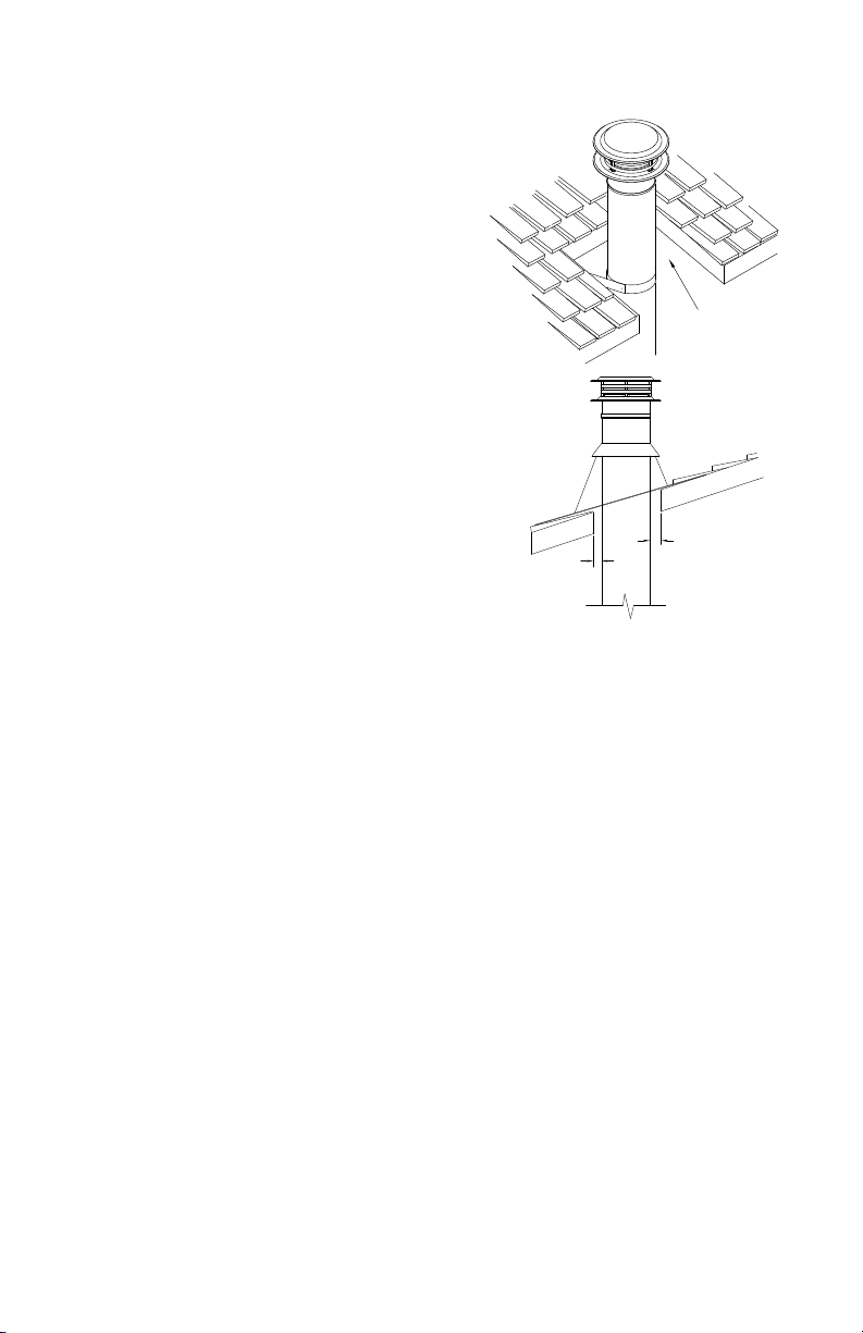
If the chimney penetrates an overhang, frame
for at least 2 inches of clearance, and install
Roof Radiation Shields (required for 18”-24”
diameter chimney only), Flashing and Storm
Collar as described in Steps 7, 10 & 11 for
Ceiling Supported Installations. Another
option is to cut away the overhang for a 2-inch
clearance (Fig 22). If the chimney extends
more than 4 feet above the top Wall Strap
or Flashing, use an Extended Roof Support
Bracket.
8. Install Chase Top Flashing: It is
recommended that a Tee Supported Chimney
be enclosed in a chase. If a chase enclosure
has been constructed, you can either use a
standard at-roof ashing, or you can use
a Chase Top Flashing. Using a Chase Top
Flashing allows for a lower prole for the
chimney. The Chase Top Flashing has an
opening in the center that has a 3” larger
diameter than the the outer diameter of the
DuraTech Chimney. If the Chase Top Flashing
can t over your chase enclosure as required
(Fig 23) then install as directed, or trim as
needed. However, if the Chase Top Flashing is
smaller than your chase enclosure, the you will
need to provide a galvanized sheet capable of
covering your chase and overhanging the each
side by 1/4-1/2 inch. Attach the Chase Top
ALLOW A MINIMUM
OF 2 INCHES AIR
SPACE ON ALL SIDES
2 INCHES
2 INCHES
MINIMUM
MINIMUM
Figure 22
Flashing to the galvanized sheet using sheet
metal screws and non-hardening waterproof
sealant. Use the Chase Top Flashing Spacers
to allow the proper air-gap clearances on the
galvanized sheet. The Chase Top Flashing
Spacers are available to insure that the
proper air-gap is maintained. Figure 23
displays in some detail, how these air gaps
are established using the Spacers and Chase
Top Flashing. Secure the Chase Top Flashing
to the chase using a sufcient number of #8,
1-1/2” wood screws, being careful to insure
the air gap is maintained between the ashing
and the chase. Seal the screw heads with
non-hardening sealant. Install the Storm Collar
directly down on top of the collar of the Chase
Top Flashing.
17
Page 18
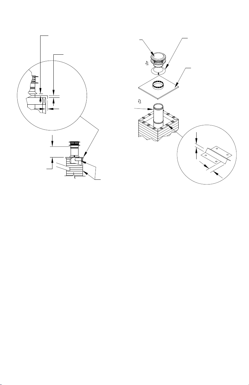
STORM COLLAR SITS DOWN ON COLLAR
OF CHASE TOP FLASHING. TIGHTEN
SO THERE IS AT LEAST 1" CLEARANCE
BETWEEN STORM COLLAR AND
FLASHING.
3/8 INCH AIR SPACE
ESTABLISHED BY SPACERS
CHIMNEY
CAP
STORM
COLLAR
CHASE TOP
FLASHING
3/8 INCH
AIR
SPACE
6 INCH MINIMUM
CLEARANCE
BETWEEN BOTTOM
OF CAP AND CHASE
TOP FLASHING
FRAMED CHASE
ENCLOSURE
Figure 23
MASONRY FIREPLACE
INSTALLATIONS
1. Determine Chimney Size: Use Table 4 to
determine the correct diameter chimney for
your replace.
2. Mount Anchor Plate: Chimneys for
masonry replaces begin with an Anchor Plate
or Anchor Plate with Damper. Warning: Anchor
Plate with Damper is not allowed in chimneys
serving stoker-red, liquid or gas burning
appliances. Caution: Do not install Anchor
Plate with Damper on Factory-built replaces.
Important: be sure the surface of the masonry
chimney has a level surface on which to attach
the Anchor Plate or Anchor Plate. If the top of
the masonry does not have a level surface,
then you will need to modify the masonry
accordingly. Center the Anchor Plate over
18
CHIMNEY
SECTIONS
CHASE TOP
FLASHING SPACER
3/8 INCH
3/8 INCH
the masonry ue opening. If a Damper is
used, make sure nothing interferes with the
damper plate movement. Seal the Anchor
Plate in place with a high temperature sealant.
Secure Anchor Plate with (4) 2” x 1/4” masonry
anchors (Fig. 24).
3a. Damper Plate: The Damper Plate should
swing freely once the Anchor Plate is installed.
When the chain is pulled down, the damper
plate should close (horizontal position). When
the chain is released (no weight on the chain),
the damper should swing open (vertical
position).
3b. Lintel Hook: With the damper plate in
the closed (horizontal) position, determine
and mark the location for the Lintel Hook. The
Lintel Hook should be mounted in a position
so as to provide a small amount of tension in
the spring attached to the chain (Fig. 25). The
Page 19

tension is needed to prevent the damper plate
from rattling when closed. Mount the Lintel
Hook to the masonry with the screws provided.
4. Attach Chimney: Attach the rst Chimney
Section onto the Anchor Plate by using the
sheet metal screws provided.
5. Finish Chimney: Install the rest of the
chimney as directed in the Ceiling Supported
Installation section, Steps 4 through 11.
Refer to Figure 1 and Table 4 for chimney
height requirements. Always maintain at least
2 inches of clearance to combustible materials,
and enclose the chimney where it passes
through occupied areas. The 2-inch clearance
is an air space; do not ll that clearance space
with any materials. Use a Wall Strap for every
four (4) feet of chimney height.
HI-TEMP
SEALANT
ANCHOR PLATE
OR ANCHOR
PLATE WITH
DAMPER
Figure 24
MASONRY
ANCHORS
NOTE:
DAMPER PLATE
IS CLOSED WHEN
CHAIN IS HOOKED
ON LINTEL HOOK
Figure 25
ANCHOR PLATE
WITH DAMPER
LINTEL HOOK
19
Page 20
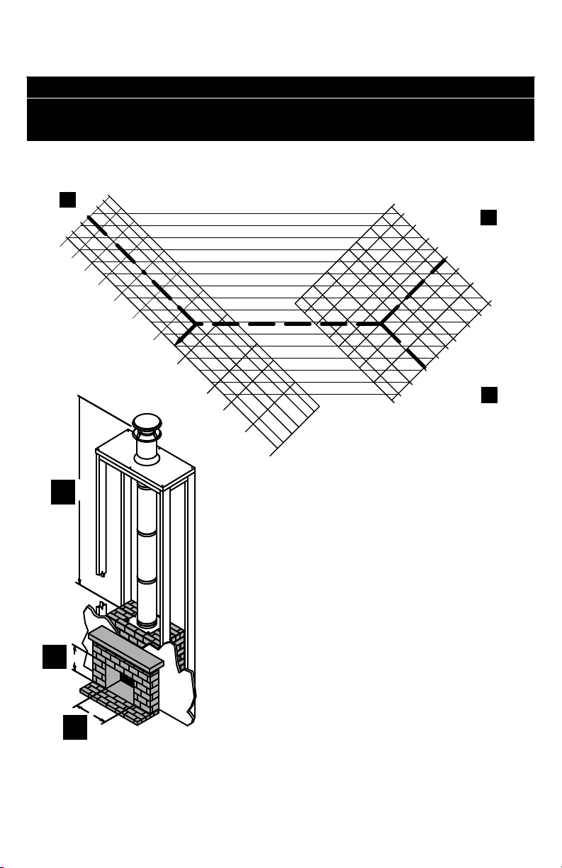
T Table 4
and 30” high, and the chimney height as 20’.
Example shows replace opening as 36” wide
12” diameter pipe.
The correct ue size for the sample problem is
Dotted line represents sample problem.
T
T
W
W
H
H
HEIGHT
WIDTH
(FEET)
HEIGHT
CHIMNEY
FIREPLACE
OPENING (INCHES)
8
7
6
30
16
14
20
8
10
15
12
10
50
40
30
24
48
60
36
42
72
36
30
42
24
48
18
18
20
22
24
20
18
60
72
84
84
and 30” high, and the chimney height as 20’.
Example shows replace opening as 36” wide
12” diameter pipe.
The correct ue size for the sample problem is
Dotted line represents sample problem.
T
T
W
H
(FEET)
HEIGHT
CHIMNEY
FIREPLACE
OPENING (INCHES)
8
7
6
30
16
14
20
8
10
15
12
10
50
40
24
48
60
72
30
18
20
22
24
20
18
84
Chimney Sizing Chart for Fireplace Installations
20
Page 21

CHIMNEY MAINTENANCE
1. Creosote and Soot: When wood is burned
slowly, it produces tar and other organic
vapors, which combine with expelled moisture
to produce creosote. The creosote vapors
condense in the relatively cool chimney ue
of a slow-burning re. As a result, creosote
residue accumulates on the ue lining. When
ignited, this creosote makes an extremely hot
re.
2. Access: Chimneys must be installed so
that access is provided for inspection and
cleaning.
3. When to Clean: The chimney should be
inspected at least once every month during the
heating season to determine if creosote or soot
has built up. Check spark arrestor screens
at least every 2 to 4 weeks. If creosote or
soot has accumulated, it should be cleaned or
replaced to reduce the risk of chimney re.
4. How to Clean: Have your chimney
cleaned by a professional chimney sweep if
you have doubts about your ability to clean
it. Use a plastic, wood, or steel brush. Do
not use a brush that will scratch the stainless
steel liner of your chimney. Scrub the spark
arrestor with a wire brush. To remove the
Chimney Cap for cleaning, unscrew the eight
(6) screws that attach the cap to the previous
chimney section. The Tee Cleanout Cap can
be removed once the retaining bar has been
unbolted. Remember to replace the Tee
Cap and retaining bar when you are nished
cleaning the chimney.
6. Chemical Cleaners: Use chemical
cleaners only as a last resort, and use only
those which the manufacturer specically
warrants as being noncorrosive to the chimney.
DuraVent will assume no liability for damage
resulting from the use of chemical cleaners.
7. In Case of Fire: If a ue re occurs,
close all appliance air inlets, and call your
Fire Department. Do not use the chimney
again, until it has been inspected for possible
damage.
8. Painting: As an option, you can coat all
exterior metal parts, with the exception of the
Chimney Cap, with high temperature, rust
proof paint. Wash the metal with a vinegar and
water solution before painting. Painting the
chimney will help to increase chimney life.
9. Creosote Formation: DuraVent assumes
no liability for structural damage or roof
contamination as the result of creosote
formation. It is the owner’s responsibility
to comply with inspection and cleaning
requirements as described in these
instructions, and those of the appliance
manufacturer.
5. Coal: To reduce corrosion in chimneys
where coal is burned, clean the chimney
thoroughly within 48 hours of shutting down
the appliance for the season.
21
Page 22

22
Page 23
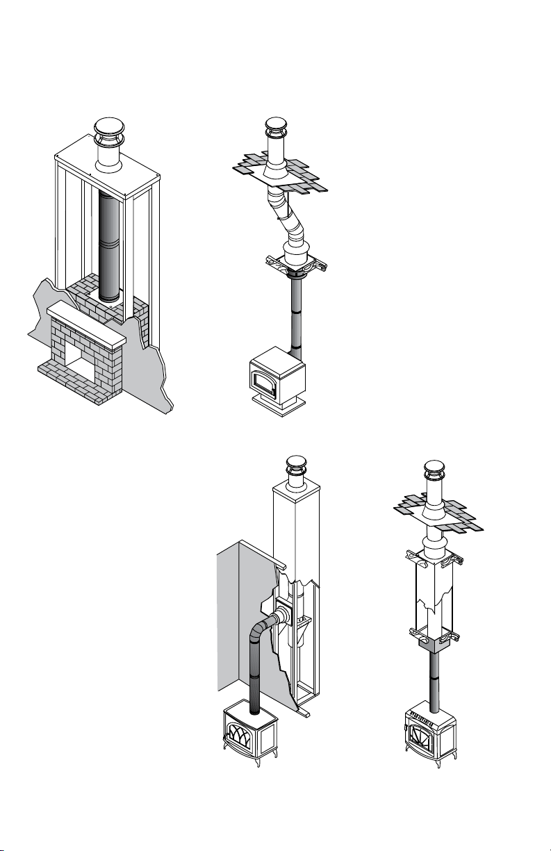
TYPICAL INSTALLATIONS
7
Fireplace Attic Offset
Through-the-Wall Two Story
23
Page 24

M&G DURAVENT WARRANTY
M&G DuraVent, Inc. (“DuraVent”) provides this limited lifetime warranty for all of its products to the original purchaser, with the exception of Ventinox (lifetime),
DuraBlack (ve years) and all Termination Caps (ve years). Subject to the limitations set forth below, DuraVent warrants that its products will be free from
substantial defects in material or manufacturing, if properly installed, maintained and used. This Warranty is non-transferable with the exception of Ventinox
which is transferable from the original homeowner to the buyer of the home for a period of ten (10) years. This warranty does not cover normal wear and tear,
smoke damage or damage caused by chimney res, acts of God, or any produc t that was: (1) purchased other than from an authorized DuraVent dealer, retailer
or distributor; (2) modied or altered; (3) improperly serviced, inspected or cleaned; or (4) subject to negligence or any use not in accordance with the printed
materials provided with the product as determined by DuraVent. This limited lifetime warrant y applies only to par ts manufactured by DuraVent.
DuraVent provides the following warranties for its products: One Hundred Percent (100%) of the purchase price or MSRP at time of purchase, whichever is lower,
for 15 years from the date of purchase, and Fift y Percent (50%) thereafter, except for the following limitations: Ventinox liner and components in wood, oil, wood
pellet, and gas installations are warranted at One Hundred Percent (100%) for the lifetime of the original homeowner; Ventinox 316 liner and components for
coal burning installations which are warranted One Hundred Percent (100%) for ten years; all Termination Caps and DuraBlack® are warranted at One Hundred
Percent (100%) for ve years, and at Ten Percent (10%) thereafter.
All warranty obligations of DuraVent shall be limited to repair or replacement of the defective product pursuant to the terms and conditions applicable to each
product line. These remedies shall constitute DuraVent’s sole obligation and sole remedy under this limited warranty. This warranty provides no cash surrender
value. The terms and conditions of this limited lifetime warranty may not be modied, altered or waived by any action, inaction or representation, whether oral
or in writing, except upon the express, written authority of an executive ocer of DuraVent.
VENTI NOX WAR RANTY CON DITIONS
Liner and Component warranties contained herein are subject to the following conditions: (1) The Liner and Components must be installed according to DV’s
installation instructions; (2) The Liner and Components are used only to line or reline chimneys venting residential appliances for which the liner was intended;
and (3) documented annual inspection of the Liner and Components and maintenance as deemed necessary, beginning one year after the date of installation
and continuing throughout the warranty period, by a Nationally Certied Chimney Sweep or VENTINOX® installer. The Liner and Components warranty is further
subject to compliance with the following requirements throughout the warranty period: The chimney must have a chimney cap and chemical chimney cleaners
must not be used when cleaning the Liner or Components. Plastic-bristle ue cleaning brushes are recommended. Corn, biofuels, driftwood or other wood
containing salt, preservative-treated lumber, plastic and household trash or garbage, or wood pellets containing such materials must not be burned in the
appliance or replace. In case of a chimney re, the chimney must be inspected and approved by a certied Chimney Sweep before reuse. After each annual
inspection, maintenance, and cleaning, the certied Chimney Sweep must ll out and date the appropriate section of the warranty card provided with the
chimney liner.
LIMITATIONS ON INTERNET SALES:
Notwithstanding any other terms or conditions of this limited lifetime warranty, DuraVent provides no warranty for the following specic products if such
products are both: (a) purchased from an Internet seller; and (b) not installed by a qualied professional installer: DuraTech®, DuraPlus HTC®, PelletVent Pro®,
FasnSeal®, and DuraVent’s relining products including DuraLiner®, DuraFlex® 304, DuraFlex® 316, DuraFlex® Pro, DuraFlex® SW, and Ventinox®. For purposes of
this warranty, a trained professional installer is dened as one of the following: licensed contractors with prior chimney installation experience, CSIA Certied
Chimney Sweeps, NFI Certied Specialists, or WETT Certied Professionals.
DuraVent reserves the right to inspec t defective produc t to determine if it qualies for replacement under the terms of this limited lifetime warranty. All warranty
claims must be submitted with proof of purchase. Labor and installation costs are not covered under this warranty. To obtain warranty service contact DuraVent
promptly at DuraVent Warranty Service, 902 Aldridge Rd., Vacaville CA 95688, or call 800-835-4429.
WHERE LAWFUL, DuraVent DISCLAIMS ALL OTHER WARRANTIES, INCLUDING BUT NOT LIMITED TO IMPLIED WARRANTIES OF MERCHANTABILITY AND FITNESS
FOR A PARTICULAR PURPOSE. IN NO EVENT WILL DuraVent BE LIABLE FOR INCIDENTAL, CONSEQUENTIAL, PUNITIVE OR SPECIAL DAMAGES OR DIRECT OR
INDIRECT LOSS OF ANY KIND, INCLUDING BUT NOT LIMITED TO PROPERTY DAMAGE AND PERSONAL INJURY. DuraVent’S ENTIRE LIABILITY IS LIMITED TO THE
PURCHASE PRICE OF THIS PRODUCT. SOME STATES DO NOT ALLOW LIMITATIONS ON IMPLIED WARRANTIES, OR THE EXCLUSION OR LIMITATION OF INCIDENTAL
OR CONSEQUENTIAL DAMAGES, SO THE ABOVE LIMITATIONS AND EXCLUSIONS MAY NOT APPLY TO YOU. THIS LIMITED WARRANT Y GIVES YOU SPECIFIC LEGAL
RIGHTS, AND YOU MAY ALSO HAVE OTHER RIGHTS THAT VARY FROM STATE TO STATE.
For the most up-to-date installation instructions, see www. duravent.com
REV 7.20.2010
M&G DuraVent, Inc. PO B ox 1510 Vacaville CA 95696-1510
Manufactured in Vacaville CA and Albany NY
Customer Service Support 800-835-4429 707-446-4740 FAX www.duravent.com
DuraTech is a registered trademark of the M&G DuraVent, Inc.
All rights reserved. Made in the USA. M&G DuraVent is a member of M&G Group. ©2011
L151 03/2011
 Loading...