

Page 1
INSTALLATION
INSTRUCTIONS
Boiler and Engine Exhaust Chimney Systems
Grease Duct Systems
Double Wall Construction Positive Pressure Chimney Systems
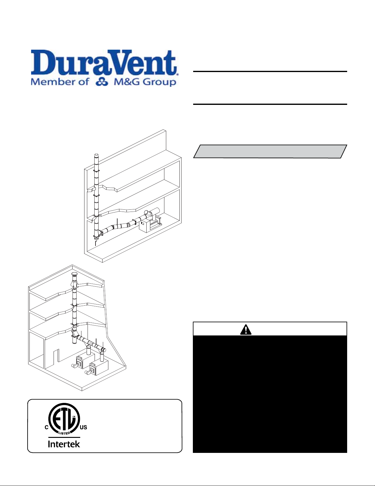
MODELS DIS / DAS
DIS: INSULATED
DAS: UNINSULATED
This installation manual will enable you to obtain a safe, efficient and
dependable installation of this positive pressure chimney system.
Please read and understand these instructions before beginning your
installation.
(DIS only)
Listed to standards:
UL 103 and ULC S604
UL-1978 (DIS only)
ULC/ORD-C959 540°C and 760°C
Report # 3162834
Do not alter or modify the components of this chimney system under any
circumstances. Any modification or alteration of the chimney system
or approved accessories, including but not limited to the appliance
it is connected to, may void the warranty, listings and approvals of
this system and could result in an unsafe and potentially dangerous
installation.
SUITABLE FOR POSITIVE PRESSURE VENTING APPLICATIONS WITH
MAXIMUM 60” WATER COLUMN INTERNAL STATIC PRESSURE AT
1000 DEGREES F.
SAVE THESE INSTRUCTIONS
FOR FUTURE REFERENCE
WARNINGS
FAILURE TO FOLLOW THESE INSTALLATION
INSTRUCTIONS COULD CAUSE FIRE, CARBON
MONOXIDE POISONING, OR DEATH. IF YOU ARE
UNSURE OF INSTALLATION REQUIREMENTS, CALL
THE PHONE NUMBER LISTED ON THE BACK OF
THESE INSTRUCTIONS.
A MAJOR CAUSE OF CHIMNEY RELATED FIRE IS
FAILURE TO MAINTAIN REQUIRED CLEARANCES
(AIR SPACES) TO COMBUSTIBLE MATERIALS. IT
IS OF UTMOST IMPORTANCE THAT THIS CHIMNEY
BE INSTALLED ONLY IN ACCORDANCE WITH THESE
INSTRUCTIONS.
PIDIS REV. 2 04/2013
Page 2

TABLE OF CONTENTS
Introduction ............................................................................ page 2
Testing / listing information .................................................... page 2
Section A - General information ................................ page 2
Features ............................................................................. page 2
Application ......................................................................... page 3
Surrounding / enclosure .................................................... page 3
Boiler and engine exhaust .......................................... page 3
Grease duct ................................................................ page 3
System sizing .................................................................... page 3
Part numbers ..................................................................... page 4
Effective length .................................................................. page 4
Clearances ......................................................................... page 4
Opening through combustible construction ....................... page 4
Chimney and fitting joint assembly .................................... page 5
Support methods and height limits .................................... page 6
Thermal expansion ............................................................ page 6
Chimney weight ................................................................. page 7
Chimney guying and spacing ............................................. page 7
Termination height ............................................................. page 8
Multi-engine exhausts not recommended .......................... page 8
Section B - Tees, elbows, increasers .......................... page 9
Tees ................................................................................... page 9
Increaser, step or tapered .................................................. page 10
Elbows ............................................................................... page 10
Offsets ............................................................................... page 11
Section C - Structural support and guiding .................... page 12
Anchor plate ..................................................................... page 12
Length Anchor Plate .......................................................... page 12
Anchor plate ventilated ...................................................... page 12
Wall support ..................................................................... page 14
Wall guide ......................................................................... page 14
Floor guide ........................................................................ page 15
Suspension band ............................................................... page 15
Roof brace ......................................................................... page 16
Guy wire ........................................................................... page 16
Section D - Roof and wall penetrations ........................ page 17
Roof / floor penetration .................................................... page 17
Wall penetration ................................................................. page 17
Section E - Terminations, starting adaptors, drain length
and relief valve ............................................ page 18
Single wall adaptor ............................................................ page 18
ANSI flange adaptor ........................................................... page 18
Flanged adaptor ................................................................. page 18
DIS/DAS to DCT and DCT to DIS/DAS adaptor .................. page 18
Rain cap ............................................................................. page 19
Finishing cone ................................................................... page 19
Flip top ............................................................................... page 19
Miter cut ............................................................................ page 19
Drain length ....................................................................... page 20
Relief valve ........................................................................ page 20
Section F - Thermal expansion ................................... page 21
Thermal expansion ............................................................ page 21
Expansion joints installation .............................................. page 21
Bellows expansion joint ..................................................... page 21
Adjustable length ............................................................... page 23
Variable length ................................................................... page 24
Section G - Grease duct application ................................page 26
Access ...............................................................page 26
Use and installation of individual parts ........................page 26
Horizontal drain length ...........................................page 26
Nozzle section ......................................................page 26
Square to round adaptor .........................................page 26
Grease tee 90° .....................................................page 27
Grease tee Y ........................................................page 27
No tool access door ...............................................page 28
Fan adaptor plate ..................................................page 29
Maintenance ........................................................page 29
Section H - Markings ..................................................page 30
2
Product reference information ......................................page 32
INTRODUCTION
Duravent Model DIS or DAS Chimney are cylindrical, prefabricated,
modular venting systems incorporating
designed for both quick assembly and pressure sealing capability. Model
DIS incorporates a
The circular cross section and high quality stainless steel inner
lated.
flue construction provide for a system with high strength-to-weight ratio
and low friction losses.
2” of mineral fiber insulation while DAS is air insu-
a unique extended inner flange
TESTING / LISTING INFORMATION
Duravent model DIS and DAS venting systems are listed with Intertek
Testing Services (ETL) to UL/ULC standards:
U.S.A.
• UL-103
- 60 in. Positive Pressure Chimney
- Building Heating Appliance Chimney
- 1400°F Chimney
• UL-1978 Grease Duct
(DIS only)
CANADA
• ULC/ORD C959
- 540°C (1000°F)
- 760°C (1400°F)
• ULC S604
Models DIS and DAS are code compliant when installed as per the
Installation Instructions with : NFPA211; NFPA31; NFPA37; NFPA96
and CSA-B149
When installed in accordance with it’s installation, Models DIS and DAS
comply with the following codes :
- NFPA (National Fire Protection Association)
- SBCCI (Southern Building Code Congress International)
- ICBO (International Conference of Building Officials)
- BOCA (Building Officials and Code Administrators)
- ICC (International Code Congress)
SECTION A - GENERAL INFORMATION
These instructions comprise both general guidelines and special requirements for all parts in the product line. Before specifying a design
or beginning an installation please carefully review these instructions.
Maintenance Notes:
Chimney Cleaning: This applies to cleaning other than standard natural
gas chimney applications where minimal maintenance is necessary.
Keep your chimney clean. Access should be provided for the inspection and cleaning of all sections of the chimney. Have your chimney
cleaned by qualified chimney sweep. It is recommended to use a nylon
chimney brush of the correct size. Do not use a brush that will scratch
the stainless steel interior of the chimney.
FEATURES
Models DIS and DAS are prefabricated modular venting systems design
for industrial and commercial applications. It has a unique extended inner flange for both quick assembly and pressure sealing capability. It
is a double wall construction with 2” of mineral fiber insulation for DIS
and 2” air space for model DAS. The inner flue is made of high quality
stainless steel plasma welded.
Page 3

APPLICATION
UL 103 Building Heating Appliance Chimney Listing:
Duravent models DIS and DIS chimney may penetrate a combustible
floor, wall or roof using the appropriate parts and openings sizes. See
section D “Roof & Wall Penetration” for more details.
Under this category, models DIS and DAS have been determined suitable
for venting flue gases at temperatures not exceeding 538°C (1000°F)
under continuous operating conditions from gas, liquid, oil or solid fuel
fired appliances. Also complies with operation (less than one hour)
at temperatures not exceeding 740°C (1400°F) and brief operation
(maximum 10 minutes) at temperatures not exceeding 906°C (1700°F).
Building Heating Appliance Chimneys are suitable for use with Building Heating Appliances and Low Heat Appliances as described in the
Chimney Selection Chart of National Fire Protection Association (NFPA)
Standard NO. 211.
UL 103 1400°F Chimney Listing:
Under this category, models DIS and DAS have been determined suitable
for venting flue gases at temperatures not exceeding 760°C (1400°F)
under continuous operating conditions from gas, liquid, oil or solid
fuel fired appliances. Also complies with brief operation (maximum 10
minutes) at temperatures not exceeding 906°C (1700°F). As such, it is
suitable for use with ovens and furnaces as described in the Chimney
Selection Chart of NFPA No. 211, in addition to other applications.
UL 103 Positive Pressure Listing:
Under this category, models DIS and DAS have been determined suitable for use at a maximum of 60 inch water column internal pressure.
ULC-C959 540°C and 760°C Industrial Chimneys Listing:
Under this category, models DIS and DAS have been determined suitable
for venting flue gases at temperatures not exceeding 760°C (1400°F)
under continuous operating conditions from gas, liquid, oil or solid
fuel fired appliances. Also complies with brief operation (maximum 10
minutes) at temperatures not exceeding 980°C (1800°F).
UL 1978 Grease Ducts Listing (DIS only):
Duravent model DIS chimney is tested in accordance with UL 1978
Standard and approved for Grease Duct applications when installed in
accordance with these installation instructions and National Fire Protection Association standard “NFPA 96, Standard for Ventilation Control
and Fire Protection of Commercial Cooking Operations”.
SURROUNDINGS / ENCLOSURE
Where, according to local code, no chase enclosure is necessary, models
DIS and DAS chimney may be placed adjacent to walls of combustible
construction at the clearance specified on each chimney section and
in the individual listing; see “CLEARANCES”. Contact local building or
fire officials about restrictions and installation inspection requirements
in your area.
Grease Ducts (DIS Only)
1. Model DIS grease ducts are primarily intended for installation in
noncombustible surroundings or in unenclosed installations.
2. Where model DIS grease ducts are installed in an open room and an
enclosure is not required, the minimum clearance to adjacent combustible walls shall be as shown in this section (see “CLEARANCES”). The
ducting may be located in a corner formed by two walls of combustible
construction, if the conditions above are met.
3. Other interior installations in all buildings should be as follows:
a) Where a grease duct penetrates a wall or ceiling rated for fire re-
sistance, it should be enclosed with a continuous non-combustible
enclosure extending from the lowest fire-rated ceiling or floor
above the hood, through any concealed space, to or through the
roof so as to maintain the integrity of the fire separations required
by the applicable building code provisions. The enclosure shall be
sealed around the duct at the point of penetration of the lowest
fire-rated ceiling or floor above the hood, in order to maintain the
fire resistance rating of the enclosure and shall be extended to
the exterior of the building through weather-protected openings.
b) A grease duct penetrating a ceiling, floor or wall which does not
have a fire resistance rating does not require to be enclosed, if
the clearances to combustibles are at the correct minimum for
unenclosed installations.
c) Where model DIS grease ducts extend through any story of a
building above the floor on which the connected appliances are
located, they shall be enclosed in the upper stories with walls
having a fire resistance rating of not less than one hour for
buildings of two or three stories. If the building is four stories
or more, the enclosure wall shall have a fire resistance rating of
not less than two hours.
4. Combustible roofs or roof-ceiling assemblies may be penetrated as
described in Section D – Roof and wall penetrations.
NOTE: Do not enclose with combustible materials. Refer to NFPA 96,
“ Standard For Ventilation Control And Fire Protection Of Commercial
Cooking Operations”, for installation and clearances of fire-rated
enclosures and definitions.
Boiler and Engine Exhaust
Duravent models DIS and DAS chimney are primarily intended to be
used in fire resistive noncombustible surroundings or installed unenclosed. They are not intended for use in one or two family residences.
(CAUTION: Do not enclose this chimney in a chase or passageway of
ordinary wood or other combustible material).
Where the chimney extends through any zone of a building (outside
that in which the heating appliance connected to it is located), it shall
be provided with an enclosure having a fire resistance rating equal to
or greater than that of the floor, wall or roof assemblies through which
it passes.
SYSTEM SIZING
Complete system sizing and capacity information maybe obtained from
the “Chimney, Gas Vent, and Fireplace Systems” chapter of the ASHRAE
Handbook (go to www.ashrae.org for more information). In spite of these
general sizing guidelines, it is most important that the heating appliance,
engine or turbine manufacturer’s installation instructions are followed.
Not following the equipment manufacturer’s instructions may result in
inadequate chimney performance and/or a violation of the equipment
manufacturer’s installation requirements.
3
Page 4
PART NUMBERS
OPENING THROUGH COMBUSTIBLE CONSTRUCTION
These instructions identify major model DIS / DAS parts by name and
part number.
Example:
DIS 36” length with inside diameter 14” made of ss316 inner flue and
ss304 outer casing.
DIS 14 L36 BC
Model Dia. Part Material
DAS 30° elbow with inside diameter 22” made of ss304 inner flue and
galvalume outer casing.
DAS 22 E30 CE
Model Dia. Part Material
DIS wall support for 8” diameter chimney made of galvalume.
DIS 8 WS E
Model Dia. Part Material
Use only factory-supplied components. Failure to do so will
void the certification and the warranty of the chimney system.
EFFECTIVE LENGTH
DIS / DAS
When assembling two parts together, the joint will overlap 5/8”. So effective length is nominal length minus 5/8”
Example:
Effective length
L36
L24
L18
L12
35-3/8”
23-3/8”
17-3/8”
11-3/8”
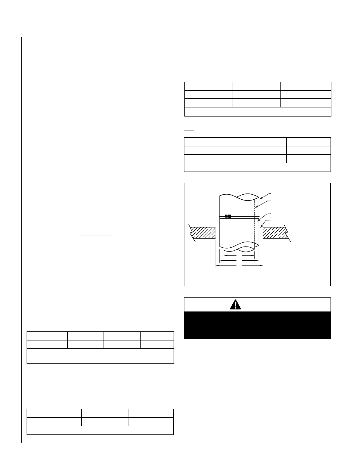
CLEARANCES
The following table serves to identify the minimum opening required when
installing a chimney through a floor, wall or roof made of combustible
material. See table 3 and figure 1.
DIS
Inside diameter (A) Roof / Floor (C) Wall (C)
Ø5” to Ø10” Inside Ø + 8” Inside Ø + 8”
Ø12” to Ø36” Inside Ø + 8” Not Listed
Table 3 - Minimum openings
DAS
Inside diameter (A) Roof / Floor (C) 1400°F Chimney (C)
Ø5” to Ø10” Inside Ø + 12” Inside Ø + 12”
Ø12” to Ø36” Inside Ø + 12” Not listed
Table 4 - Minimum openings
Chimney outside diameter
Chimney inside diameter
2” Insulation
Clearance opening
B = A + 4”
OPENINGS - Minimum open-
A
B
C
ing required when installing
a chimney through a floor,
wall or roof made of combustible material.
Figure 1
DIS
Minimum air space clearance to combustible construction to model
DIS Chimney is 1”.
For non-combustible construction, maintain clearances as required
for installation, access for inspection or per local code.
Inside diameter B.H.A Chimney 1400°F Chimney Grease Duct
Ø5” to Ø36” 1” 1” 2”
Table 1 - Minimum air space clearance to combustible construction model DIS
DAS
Minimum air space clearance to combustible construction to DAS
chimney is 4”.
Inside diameter B.H.A Chimney 1400°F Chimney
Ø5” to Ø36” 4” 4”
Table 2
4
NOTE: DIAGRAMS & ILLUSTRATIONS ARE NOT TO SCALE.
WARNINGS
DO NOT INSTALL ANY TYPE OF INSULATION IN THE
REQUIRED CLEARANCE SPACES SURROUNDING
THE CHIMNEY.
Page 5
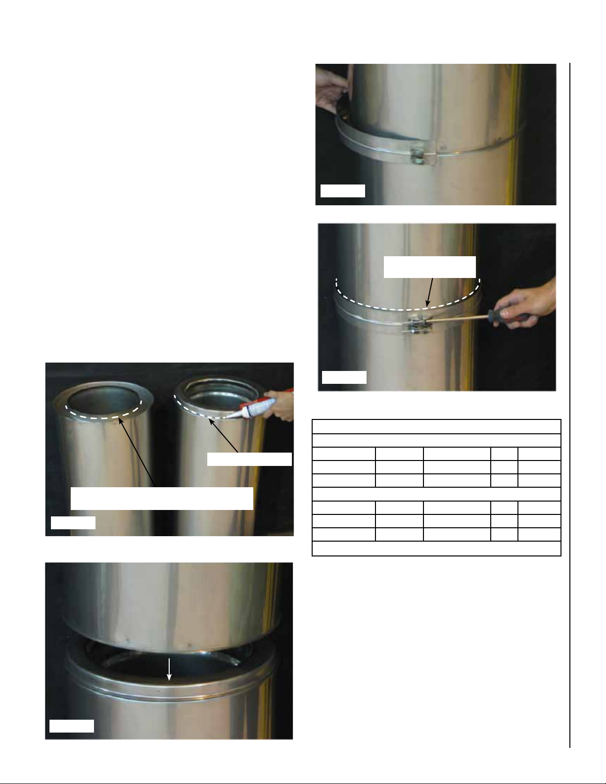
CHIMNEY AND FITTING JOINT ASSEMBLY
All components have a male and female end. The installation orientation
is indicated on the labeling of each chimney section with an arrow. The
arrow indicates the direction of the flow. Clean all inner and outer surfaces
of the male and female ends with an appropriate organic solvent, such
as acetone, Mek, or other commercial degreaser.
1. Apply a bead of S-650 sealant about 1/8” thick around the male end
of chimney and for Grease duct application, add a bead of S-2000
sealant at the edge of the female chimney (see figure 2). See table
5 for approved sealants.
2. Insert the female end, of another section of chimney, over male end
with sealant (see figure 3).
3. Insert the assembly band (see figure 4) around the joint of the two
sections assembled in step 2. A small bead of S-650 can be applied
on the inner groove of the band prior to installation for better leak
tightness.
4. Using a phillips screwdriver, connect the two ends of the band as
shown in figure 5.
5. Where the chimney is installed outside, an exterior sealant S-375
must be applied at the upper joint of the band and the outer casing,
see figure 5.
Figure 4
Apply S-375 sealant here
for exterior installation
Grease Duct Application: Add a bead of S-2000 sealant
at the edge of the female end.
Figure 2
Add S-650 sealant here
Figure 5
SEALANT USAGE
Interior Installation
Sealant Application Supplier Model Color Max. Temp.
Joints Duravent S-650 red 650°F
Inner Flue Duravent S-2000 White 2000°F
Exterior Installation
Sealant Application Supplier Model Color Max. Temp.
Joints Duravent S-650 red 650°F
Outer Band Duravent S-375 gray 375°F
Table 5
CAUTIONS
A. DO NOT ALLOW SCREWS TO PENETRATE THE INNER FLUE.
THIS CAN CAUSE CORROSION, GAS LEAKAGE OR EXPANSION
FAILURE.
B. NEVER USE SCREWS THROUGH THE OUTER CASING OF AN
ADJUSTABLE LENGTH OR EXPANSION JOINT.
Figure 3
C. OBSERVE ADEQUATE SAFETY MEASURES WHEN USING A
DEGREASER.
NOTE: DIAGRAMS & ILLUSTRATIONS ARE NOT TO SCALE.
5
Page 6
SUPPORT METHODS AND HEIGHT LIMITS
1. Several support and guiding methods are used to anchor a chimney
against upward, downward and angular displacement.
2. These supports and guides used with thermal expansion devices,
prevent bending stresses on the chimney elbows and joints.
3. Supports and guiding methods and installation are described in Section C. Certain limitations apply for proper installation of supports
and guides. See tables 6 and 7.
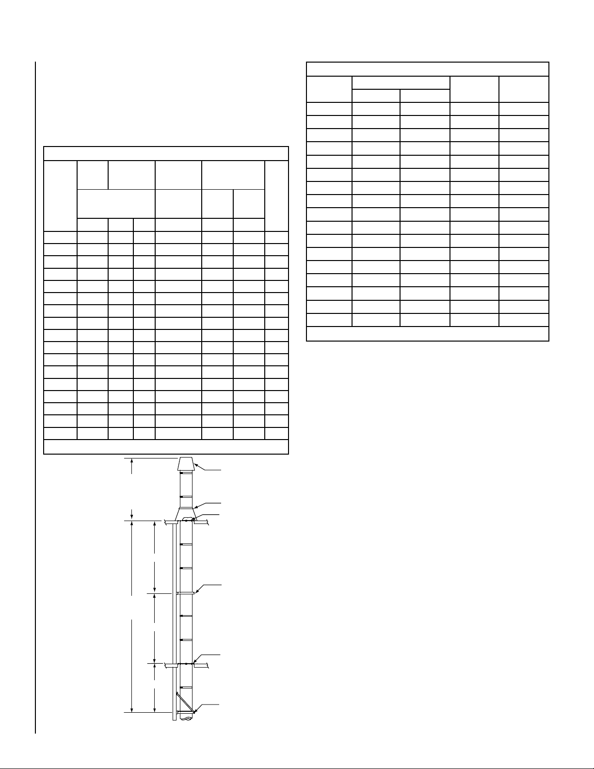
MAXIMUM CHIMNEY HEIGHTS AND SUPPORT METHOD FOR MODEL DIS AND DAS
Anchor
Inside
Diameter
(in)
DIS/DAS
5
6
8
10
12
14
16
18
20
22
24
26
28
30
32
34
36
Anchor Plate
Plate
with Length
(AP)
Metal Frame Only
DIS DAS
200 200
147
128
200 200
200 200
103
177 200
86
73
152 194
64
133 175
57
118 146
106 135
53
97 125
48
44
89 117
76 92
37
35
71 88
33
66 83
63 76
31
59 73
29
56 70
27
53 65
26
(APL)
Ventilated
Anchor Plate
(APV)
Metal Frame
OR Wood
Frame
DIS/DAS DIS/DAS
133 147
116 128
93 106
78 86
66 73
58 64
52 57
48 53
43 48
40 44
34 37
32 35
30 33
28 31
26 29
25 27
23 26
Wall Support (WS)
Frame
Metal
Wood
Frame
DIS/DAS
61 105
53
43
35
30
27
24
22
20
18
15
14
13
13
12
11
11
Tee
(T)
92
74
61
53
46
41
38
34
31
27
25
23
22
21
20
18
Table 6 - Dimensions are in feet
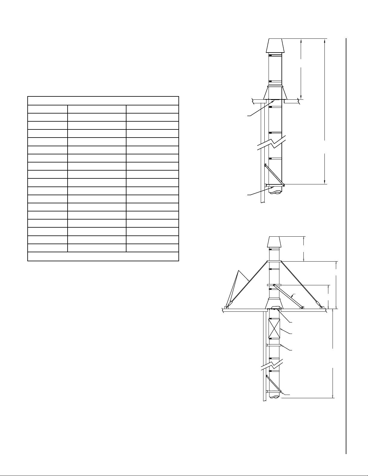
See Dim. “H” figure 7
and Chimney Guying
and Bracing in this
section.
“ M V S” d imen sion see table 7 for
Maximum Vertical
Spacing between two
guides or a support
and a guide.
NOTE: W h en t he
maximum height from
table 6 is exceeded, resupport using another
support and expansion
joint.
Maximum
height - See
table 6
MVS
MVS
MVS
Termination
Storm collar (SC)
Roof support (RS)
Wall guide (WG)
Floor guide (FG)
SUPPORT AND GUIDE SPACING FOR MODEL DIS AND DAS
Inside
Diameter (in)
5 10 8 10 12
6 10 8 10 12
8 10 8 10 12
10 10 8 10 12
12 10 8 10 12
14 10 8 10 12
16 10 8 10 12
18 10 8 10 12
20 10 8 10 12
22 10 8 10 12
24 10 8 10 12
26 10 8 10 12
28 10 8 10 12
30 10 8 10 12
32 10 8 10 12
34 10 8 10 12
36 10 8 10 12
Table 7
- Dimensions are in feet
MVS*
Interior Exterior
H** MHS***
* MVS = Maximum Vertical Spacing between two guides or a support and
a guide in a vertical position.
** H = Maximum freestanding Height above the roof.
*** MHS = Maximum Horizontal Spacing between two guides or a support
and a guide is 12 feet.
THERMAL EXPANSION
Good installation practice requires that any length of exhaust system
between two fixed points subject to more than 1/4 inch expansion must
have an Adjustable Length (LA) or Bellows Joint (LB) to compensate
for expansion. Models DIS and DAS will expand approximately 1 inch
for every 100°F temperature rise per 100 feet of chimney. To accommodate chimney movements, any wall guide or floor guide must be
located away from the locking band.
It is essential that these parts be properly installed and provided with
adequate support and guidance to prevent binding or excessive bending forces. (See detailed installation information contained on page 19,
Thermal Expansion).
Figure 6 - Maximum chimney heights and support
6
Wall support (WS)
NOTE: DIAGRAMS & ILLUSTRATIONS ARE NOT TO SCALE.
Page 7
CHIMNEY WEIGHT
Chimney weight is given in pounds per foot of chimney for each diameter.
It is important to know the weight of the chimney section for chimney
support or guiding. Chimney weight (table 8) along with maximum
chimney height (table 6) are necessary to calculate the proper anchor
strength needed with wall supports (WS), Anchor Plate (AP) supports
and Suspension Bands (SB).
CHIMNEY WEIGHT IN LB/FT
Inside diameter Model DIS Model DAS
5 7 4
6 8 5
8 10 6
10 12 8
12 14 9
14 16 10
16 18 12
18 20 13
20 22 14
22 24 15
24 28 19
26 30 20
28 32 21
30 34 23
32 36 24
34 38 25
36 40 27
Table 8
Example: Model DIS, 6” diameter section of 25 feet in length from table 8,
weight in lb/ft = 8. Total weight 8 x 25 = 200 lbs
CHIMNEY GUYING AND BRACING
* If Dimension “H” exceeds the
value in table 7, use bracing or
cable guying to stabilize chimney section above the roof. See
notes 3, 4, 5 and figure 8.
Guide
Support
No guying or bracing required
Figure 7 - Maximum freestanding chimney height
See table 7 for “H” dimensions
Guy Cable * tensioners and
roof anchors * (by others)
H*
Maximum Height
See table
H
Brace
H
5’ MAX
1. Proper guying and bracing is essential for part of the chimney that
extends above the roof or parapet wall. The chimney at this point is
subject to wind conditions and needs special attention for proper
stabilization.
2. If the stack above the roof does not exceed dimension H, no special
guying or bracing is required. However, to protect the flashing from
lateral movement, a guide must be installed at the roof level. See figure
7).
3. For stack height above the roof that needs guying or bracing, a support,
a small length and a expansion length must be installed near the roof
level to absorb the thermal expansion and minimise this effect on the
guy wires or brace.
4. When using guy wire, the cable must be slightly slack or loose to allow
thermal expansion.
5. When using rigid bracing, the maximum vertical height between supports must be reduced to 5’ to compensate thermal expansion.
NOTE: DIAGRAMS & ILLUSTRATIONS ARE NOT TO SCALE.
Support
* Cables and roof anchors
designed for 30 lb. per
sq. ft. force on chimney
projected area.
Expansion Length
Guide
See table 6
Support
Figure 8 - Chimney height with rigid bracing or guying option
Maximum
height -
7
Page 8

TERMINATION HEIGHT
MULTI-ENGINE EXHAUST SYSTEMS
Chimneys and vents shall terminate above the roof level in accordance
with the following requirements:
1. Five feet above the roof level or any adjacent flat roof, wall parapet
or air intakes, and/or in accordance with the following NFPA 211
requirements.
2. Where chimney terminates at less than 10 feet from any adjacent
ridge, wall or parapet, the chimney shall terminate at minimum of 3
feet above the ridge, wall, or parapet.
3. Where chimney terminates at more than 10 feet from ridge, wall, or
parapet, a minimum height of 2 feet shall be required above the ridge
wall or parapet.
A common exhaust system for multiple engine or turbine installations
is generally not recommended. A separate exhaust system should be
provided for each engine or turbine.
Check with your engine or turbine manufacturer prior to common exhaust system design. Exhaust gas from operating units tends to flow to
non-operating units where condensation may form. WATER IN ENGINE
OR TURBINES AT START-UP MAY CAUSE DAMAGE. IN GENERAL,
A SEPARATE EXHAUST SYSTEM SHOULD BE PROVIDED FOR EACH
ENGINE OR TURBINE.
8
NOTE: DIAGRAMS & ILLUSTRATIONS ARE NOT TO SCALE.
Page 9
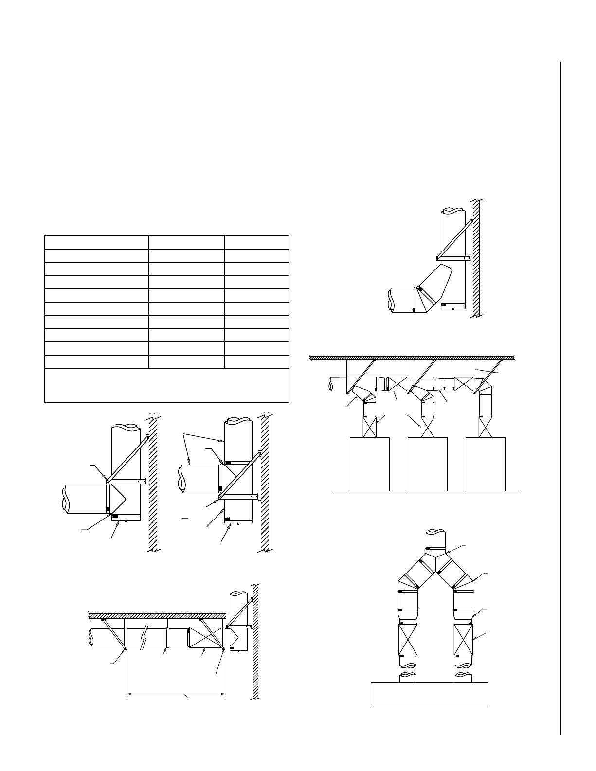
SECTION B - TEES, ELBOWS, INCREASERS
90° TEE (T90)
1. Generally used to connect the horizontal length from the appliance to the
vertical length when clean-outs access or drain is required.
2. 90° should not be used for changing flow direction in diesel or turbine
exhaust.
3. For supporting the tee, the preferred location is above the tee (see figure
9).
4. If it is not possible to suspend the tee, it may be supported from the
base (see figure 10). When this is necessary, a short length should be
installed between the tee and the tee cap or Drain-Tee Cap for a good
clean-out or inspection access.
IMPORTANT NOTE:
If more than 1/4” of thermal expansion is expected between a stationary
point and the tee, the use of an expansion length and a two axis support
is recommended to minimize bending moments on the tee (see figure 11
and table 9).
Gas Temperature Rise Maximum Length Expansion
200°F 12’0” 0.25”
300°F 8’0” 0.25”
400°F 6’0” 0.25”
500°F 5’0” 0.25”
600°F 4’0” 0.25”
700°F 3’6” 0.25”
800°F 3’0” 0.25”
900°F 2’6” 0.25”
1000°F 2’0” 0.25”
Note: 60°F - 70°F ambient T°
Table 9 - Maximum allowable length between two fixed points
without expansion length
Lengths
45° TEE (T45)
1. For systems where flow resistance must be minimized like engine or
turbine exhaust. The use of a 45° tee is suggested. It can be combined
with a 45° elbow to make a smooth 90° turn (see figure 12). To support
this tee, use similar method as a 90° tee.
2. When using 45° tee to connect multiple appliances together, thermal
expansion must be considered. Thus prepared to prevent bending moments on the tee, an expansion length must be installed between the tees
(see figure 13).
45° TEE Y (TY)
1. This kind of tee is useful where the stack is located between two application or with a double exhaust system. Use the same support method and
thermal expansion considerations from the other tees (see figure 14).
Figure 12 - Smooth 90° Turn
Stationary / Fix
Support
45° Tee
Expansion
Length
Increaser
Wall
Support
Tee
Tee Cap or
Drain-Tee Cap
Figure 9 - Suspended Tee
Stationary
Support
Suspension
Figure 11 - Two Axis Support
Tee
Wall Support
Short Length
Tee Cap or
Drain-Tee Cap
Figure 10 - Base Supported Tee
Expansion
Band
expansion between two stationary points
Length
Stationary
Support
More than 1/4” of expected thermal
NOTE: DIAGRAMS & ILLUSTRATIONS ARE NOT TO SCALE.
Appliance Appliance
Appliance
Figure 13 - Multiple appliance connection with 45° tees
45° Tee Y
45° Elbow
Increaser
Expansion
Length
Appliance
Figure 14 - 45° Tee Y
9
Page 10
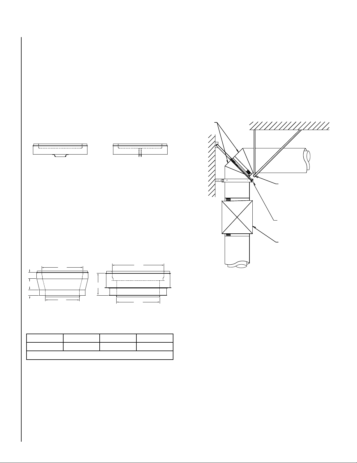
TEE CAP (TC)
ELBOWS
1. Use to block one of the openings of horizontal or vertical tee.
2. Removable, it facilitates access for inspection and maintenance of
the chimney.
3. The installation is the same as for lengths.
4. When removed, the old silicone must be cleaned out and a new bed
of sealant must be applied.
DRAIN-TEE CAP (DTC)
1. Use as a drain for vertical stack.
2. Connect to a suitable drain fitting to allow rain entering the chimney
to wash down, dilute and remove any corrosive residue.
3. Same installation as a tee cap.
Tee cap
Drain-Tee Cap
Figure 15 - Tee cap and Drain-Tee Cap
INCREASER, STEP OR TAPERED
1. Use to increase the diameter of the chimney flue.
2. The tapered increaser induce less pressure drop than the step increaser, but requires more space. It has a 15° side angle and provides
increases of one, two or three size. The height of the fitting varies
depending on the diameters to be increased (see figure 17).
3. The tapered increaser have the same load strength as a standard
length, but the step increaser is a non-structural part and must be
protected from axial and lateral load.
1. Elbows are used for changes in direction in horizontal or vertical
portions of a chimney system.
2. All elbows feature the standard joint assembly as described in Section
A - Chimney and Fitting Assembly.
3. Elbows are used in combination to make different angles ranging
from 3° to 90° in horizontal and vertical breechings of the chimney
system.
4. Elbows are not designed to take bending loads and must be structurally
supported (see figure 17). Structural parts such as posts or beams
may also be needed to hold chimney supports in position.
2X 45° Elbows
Anchor plate (A P) and
frame (by others)
Wall support (WS)
Expansion length
Ø B
2”
C*
2”
Ø A
* See table 10
6”
Figure 16 - Increaser height
STEP 1 Diameter 2 Diameters 3 Diameters
C 4” 8” 12”
Table 10 - Tapered increaser height
Ø B
Figure 17 - Supported elbow
Ø A
10
NOTE: DIAGRAMS & ILLUSTRATIONS ARE NOT TO SCALE.
Page 11

OFFSETS
1. Sloped or horizontal offsets in the vertical portion of a chimney above
the breeching should be avoided except where absolutely necessary.
2. Sloped offsets require more expansion joints and secure bracing
above and below elbows.
3. With solid fuel burning appliance, the slope must not be greater than
30° from the vertical. Appliances which are capable of burning solid
fuel or are convertible to solid fuel are limited to the same 30° slope.
4. The length of the offset is determined by strength considerations. The
maximum dimension between supports, given as the MHS dimension
in table 7, is applicable to all horizontal and sloped orientations (see
figure 18)
5. The minimum offset is accomplished with two elbows directly connected to each other (see Figure 34 and table 9).
6. With frequent re-support, there is no structural or operating limit to
the length of horizontal or sloped portions of model DIS chimney,
providing the system meets the capacity, pressure drop of available
equipment.
7. The carrying capacity of supports and their structural attachments
must take into account the weight of the offset plus whatever vertical
chimney is carried by that support.
8. Height limits for supports ar tabulated in Section A of these instructions.
9. The ends of any sloped or horizontal offset must be anchored to
prevent overstressing elbows and to assure proper operation of
expansion joints.
10. The vertical sections of chimney above the offset must also be supported or anchored and guided where necessary.
11. Models DIS and DAS Roof Support (RS), Wall Support (WS), Wall
Guide (WG) may be used in a variety of ways for offset support to
achieve the structural stability of the chimney system. Preferred
methods of using model DIS and DAS supports are shown in Section
C.
12. Re-supports such as those shown in Figure 31 must be securely
anchored to walls, posts, or locally fabricated rigid framework. This
framework must be designed to assure stability of attached model DIS
supports, such as Anchor Plate (AP) supports and Wall Supports (WS).
13. Supports suspended by threaded rods or from small size angles or
straps are usually not satisfactory to resist bending moments due
to offsets.
Offset *
* See table 11
Figure 19 - Minimum offset
Ø 3° 15° 30° 45°
5” n/a 1-3/8” 3-5/16” 5-5/8”
6” n/a 1-7/16” 3-7/16” 5-15/16”
8” n/a 1-1/2” 3-3/4-” 6-1/2”
10” n/a 1-9/16” 4” 7-1/16”
12” n/a 1-5/8” 4-1/4” 7-11/16”
14” n/a 1-11/16” 4-1/2” 8-1/4”
16” n/a 1-3/4” 4-13/16” 8-7/8”
18” n/a 1-7/8” 5-1/16” 9-7/16”
20” n/a 1-15/16” 5-5/16” 10”
22” n/a 2” 5-5/8” 10-5/8”
24” n/a 2-1/16” 5-7/8” 11-3/16”
26” n/a 2-1/8” 6-1/8” 11-3/4”
28” n/a 2-3/16” 6-3/8” 12-3/8”
30” n/a 2-1/4” 6-11/16” 12-15/16”
32” n/a 2-5/16” 6-15/16” 13-1/2”
34” n/a 2-3/8” 7-3/16” 14-1/8”
36” n/a 2-7/16” 7-1/2” 14-11/16”
Table 11 - Minimum offset
MHS
Figure 18 - Offsets MHS (refer to table 7)
NOTE: DIAGRAMS & ILLUSTRATIONS ARE NOT TO SCALE.
11
Page 12

SECTION C - STRUCTURAL SUPPORT AND GUIDING
LENGTH ANCHOR PLATE (APL)
ANCHOR PLATE ASSEMBLY (AP)
1. The anchor plate support assembly is designed to provide maximal
support to vertical sections and to provide fixed point support for
horizontal sections.
2. The plate support must be attached to the building structure or supported with rigid structural members (see figure 22 and table 12 for
bracing dimensions)
3. DO NOT ATTACH THE ANCHOR PLATE TO COMBUSTIBLE CON-
STRUCTION. If unavoidable, use the Ventilated Anchor Plate support
assembly.
4. The anchor plate consists of a plate and eight clamp flange. See
figure 21 for sectional details for plate support.
5. IMPORTANT: The surfaces of the male and female couplings
in contact with the plate of the anchor plate assembly must be
coated with inner joint sealant.
6. There are two ways of assembling parts on the support. You may
choose your method depending on your situation.
6.1 The first method consists of assembling two parts and the anchor
plate on the side and then installing this assembly on the support
structure. This method is easier and faster to install, but requires
enough clearance to insert the complete assembly through the support structure opening. If there is a tee or elbow upstream of the
anchor plate, you may not have enough clearance. Also consider
the weight of the assembled parts and make sure you have a safe
manner of lifting the assembly.
INSTALLATION STEPS FOR FIRST METHOD (refer to figure 23)
1. Place the part that will be upsteam of the support on the floor.
2. Apply a bead of inner joint sealant on the male coupling flange.
3. Slide the plate of the anchor plate support over the coupling.
4. Apply a second bead of sealant on the plate around the male
coupling where the flange of the female coupling of the next part
will mate.
5. Place the second part over the plate. Make sure the sealant completely fills joints between the plate and the female coupling.
6. Use eight clamp flanges and bolts to tightly clamp the parts to
the support.
7. Insert the assembly on the support structure and fix the plate to
the structure using the supplied hardware.
6.2 The second method is applicable when the plate of the anchor plate
support needs to be installed first, as when there is a tee or elbow
upstream of the support. May require at least two persons to complete
the installation.
INSTALLATION STEPS FOR SECOND METHOD (refer to figure 24)
1. Fix the plate of the anchor plate support to the structure using
the supplied hardware.
2. Apply a bead of inner joint sealant on the male coupling flange
of the part before the support.
3. Insert the male coupling of the part in the plate opening.
4. You may hold it using two clamp flanges placed at 180° and
bolted to the anchor plate.
5. Apply a bead of sealant on the plate around the male coupling.
6. Place the second part over the plate. Make sure the sealant completely fills the joint between the plate and the female coupling.
7. Fix the assembly by clamping it with four clamp flanges on the
unused flange positions.
8. Remove the first two clamp flanges and finish clamping the assembly.
1. Use for same application as the anchor plate (AP).
2. It is composed of a straight section - with an effective length of
3 3/4” integrated into a support plate (see Figure 20 for the detail of
the part).
3. Unlike the anchor plate (AP), the Length Anchor Plate (APL) doesn’t
need any clamp flange (and its hardware) for its installation, so it is
easier and faster to isntall.
4. The APL must be attached to the building structure or supported by
rigid NON-COMBUSTIBLE structural members (see Figure 22 and
Table 12 for bracing dimensions).
Installation steps for the APL
1. Fix the plate of the APL to the structure using the supplied hardware.
2. Follow the steps of the «Chimney and fitting assembly» section in
the section A on page 5 to connect the couplings to the APL with
the parts downstream and upstream.
Figure 20 - Length Anchor Plate (APL)
VENTILATED ANCHOR PLATE (APV)
1. Use for same application as the anchor plate, but can be attached to
combustible construction.
2. Usually uses as roof support. See section D for details on how to
install at the roof level.
3. Installation is done the same manner as the anchor plate.
4. See Figure 25 for opening dimensions through combustible construction.
5. Do not block or obstruct openings in the plate. They are intended to
minimize heat accumulation.
12
Figure 21 - Sectional detail for plate support
NOTE: DIAGRAMS & ILLUSTRATIONS ARE NOT TO SCALE.
Page 13

Height Limits - See Section A,
Table 6 for maximum support
height of Anchor Plate (AP).
NOTE: If bracing is used, minimum “X” angle is 30°. If there
is no bracing, the framework
must be attached to structural
members to provide equivalent
rigidity.
Figure 22 - Homemade brace
Method #2 - Step 1
Sealant
bead
Method #2 - Step 2
Sealant
bead
Method #1 - Step 1 and 2
Method #1 - Step 5
Sealant
bead
Method #1 - Step 3 and 4
Method #1 - Step 6
Method #2 - Step 3 and 4
Method #2 - Step 6 and 7
Method #2 - Step 5
Method #2 - Step 8
Figure 24 - Method #2 installation Steps
I.D. FRAMEWORK BRACING
5” – 20” 3” X 2” X 3/16” 2” X 2” X 1/4”
22” – 36” 4” X 2” X 1/4” 3” X 3” X 1/4”
Table 12 - Bracing DIS / DAS
Method #1 - Step 7
Figure 23 - Method #1 installation Steps
I.D. + 8” (DIS)
I.D. + 12” (DAS)
Figure 25 - Ventilated anchor plate (APV)
NOTE: DIAGRAMS & ILLUSTRATIONS ARE NOT TO SCALE.
I.D. + 8” (DIS)
I.D. + 12” (DAS)
13
Page 14

WALL SUPPORT (WS)
1. The wall support consists of an Anchor Plate and a prefabricated frame
with mounting brackets and angled struts for bracing.
2. Used to support the chimney in vertical runs, it maintains the chimney
at an adjustable distance between 2-1/2” and 7-1/2” from the wall (see
Figure 26).
3. The maximum weight allowable on the wall support depends if the
support is attached to a metal structure or a wood structure (see table
6 for maximum chimney height).
4. The installation begins by attaching the frame of the wall support to a
rigid metal or wood structure. Adjust the braces to have a minimum
of 45° angle from horizontal. Once the frame of the wall support is
fixed to a rigid structure, the installation is the same as the Anchor
Plate.
Height Limit - See Section A, table 6 for
maximum height of Wall Support (WS)
1”
(25mm)
Figure 27 - Wall guide (WG)
Wall
guide
Adjustable braces
45° Min.
Figure 26 - Adjustable wall support (WS)
WALL GUIDE (WG)
1. The wall guide is used as a lateral guide to resist lateral or side load
only, it is not designed for carrying the weight of a vertical chimney.
It also ensure a minimum clearance of 1” to combustibles for model
DIS and 4” for model DAS. See Figure 27 (wall guide).
2. The proper location to install the wall guide is immediately below a
locking band. The locking band must be able to move without interfering with the guide when thermal expansion occurs. See Figure 28
(wall guide location).
3. The wall guide can be installed with a wall band extension for greater
clearances up to 4-1/4” for model DIS and up to 7-1/4” for DAS. See
Figure 29 (wall guide extension).
4. Special considerations must be taken when installing on exterior wall.
A wall guide must be installed between 6’ and 10’ below the highest
wall support to stabilize the free standing portion of the chimney. Do
not install a expansion length in this area due to bending forces induced
by the freestanding portion. See Figure 30 (special considerations).
MVS
Wall
guide
MVS
Wall support
Figure 28 - Wall guide location
14
2” to 4-1/4” (51mm to 108mm) (DIS)
5” to 7-1/4” (127mm to 184mm) (DAS)
Figure 29 - Wall guide extension
NOTE: DIAGRAMS & ILLUSTRATIONS ARE NOT TO SCALE.
Page 15

Freestanding = H max
SUSPENSION BAND (SB)
1. Suspension band is used to support and guide the chimney in
horizontal runs. It consists of a band, a flexible strap (by others), a
trolley and a rail.
2. The trolley and rail allow up to 4” of travel to compensate thermal
expansion.
3. See section A, Table 7 for maximum distance between two supports
or guide.
4. Important: The flexible strap must be at least 3/4” wide and 0.036”
thick made of galvanized or stainless steel. YOU MUST USED TWO
LAYERS OF FLEXIBLE STRAP to attach the band to the trolley.
Rail
Do not install expansion
length in this area
6’ to 10’
Wall guide
Expansion length
Figure 30 - Special considerations for exterior installation
FLOOR GUIDE (FG)
1. The floor guide is used the same manner as the wall guide but it is
modified for use at floor penetrations. See Figure 30 (floor guide).
I.D. + 8” (DIS)
I.D. + 12” (DAS)
Trolley
Flexible strap
2X Layer (By others)
4”
Travel
THERMAL
EXPANSION
DIRECTION
Band
Figure 32 - Trolley
CRADLE SUPPORT (CS)
1. Cradle support is used to support and guide the chimney in horizontal
runs. It consists of a cradle support and suspension rod (by others).
2. The suspension rods must attached to the structural members to
provide rigidity.
3. Cradle support allows to stack two (or more) horizontal chimney
runs (See Figure 33).
4. Cradle support does not allow movement for thermal expansion.
This support should be used for low temperature application.
Figure 31 - Floor guide (FG)
I.D. + 8” (DIS)
I.D. + 12” (DAS)
NOTE: DIAGRAMS & ILLUSTRATIONS ARE NOT TO SCALE.
Rods (by others)
Cradle Support
Figure 33 - Cradle Support
15
Page 16

ROOF BRACE (RB)
GUY WIRE (GW)
1. The roof brace is used to stabilize the chimney where it extends more
than 15’ above the roof.
2. It consists of one band (RB) and two braces (supplied by the installer).
3. To minimize loads induced by thermal expansion on braces and support, the maximum distance between the last fixed support and the
band of the roof brace must be reduced to 5’.
4. Begin by attaching the braces to the band with supplied bolts and
nuts. Next, install the band on the chimney and tighten the band. Fix
the braces to the roof at 120°. Make sure you have a rigid structure
on the roof.
H
1-1/4” Rigid galvalume tube
or 1-1/2” x 3/16” angle iron
(by others)
5’ Max
1. The guy wire is used where the chimney extends more than 15’ above
the roof.
2. It consists of a band designed to receive 3 guy wire (supplied by others)
at 120° apart or 6 guy wire at 60° apart for diameter larger than 24”.
The guy wires are fixed to the roof by mean of tensioner and anchor
(also by others).
3. When installing guy wire, the cable must be slightly slack or loose to
allow thermal expansion or be equipped with tensioning springs (by
others). The tensioning springs are mandatory only when there is
more than one level of guy wire needed.
4. To minimize the effect of thermal expansion, good practice implies
installing a fixed support and an expansion length at the roof level
(see Figure 35 ’guy wire’).
* Cables and roof anchors
designed for 30 lb. per
sq. ft. force on chimney
projected area.
Guy wire band (GW)
Guy Cable * tensioners and
roof anchors * (by others)
Fixed support
H
Fixed support
Expansion length
120°
Figure 35 - Guy Wire
Figure 34 - Roof brace assembly
16
NOTE: DIAGRAMS & ILLUSTRATIONS ARE NOT TO SCALE.
Page 17

SECTION D - ROOF AND WALL PENETRATIONS
WALL PENETRATION
ROOF/FLOOR PENETRATION
1. The roof/floor penetration consist of a firestop radiant shield (FS), a
flashing (F) with a storm collar (SC) and a floor guide (FG) or ventilated
anchor plate (APV) (see Figure 36 roof/floor penetration).
2. Those components allows the chimney to penetrate a combustible roof
or floor at 2 inches clearance to combustible. See table 3 – Minimum
openings for framing dimension.
3. The radiant shield of the firestop may need to be trimmed to fit the
height of the roof. Nominal height is 10 inches.
4. Roof/floor penetration components are designed to be installed on a
flat roof. They may be installed on a pitch roof if a curb is installed
to provide a flat surface.
5. Floor guide is used to protect the flashing from lateral movement. The
ventilated anchor plate is used to protect the flashing and to provide
a re-support.
6. Do not install a chimney joint or a expansion length in the roof/floor
space.
7. For installation on non-combustibles materials, the minimum opening
can be reduced to I.D. + 6 inches. The anchor plate can also be used
instead of the ventilated version.
8. Always seal, with outer joint sealant, between storm collar and outer
chimney casing.
9. Installation step:
a. Cut opening to dimensions specify in table 3.
b. Install the Firestop under the roof/floor and attach it with screw.
c. Slide DIS / DAS chimney trough the firestop.
d. Install the floor guide or the ventilated anchor plate on top of the
roof/floor.
e. Install flashing over the chimney and the guide/support and
screw it.
f. The storm collar is placed around the chimney and sealed to the
casing with outer joint sealant. The storm collar should not quite
rest on the flashing when the chimney is cold (1/4” gap between
the collar and the top of the flashing).
1. This part is used to allow model DIS / DAS chimney to pass trough a
wall made of combustible construction.
NOTE: Crossing a combustible wall is not permitted for diameters
larger than 10” inside diameter.
2. The wall penetrator (FSW) consist of a firestop female half and a male
half that slide in each other to adjust wall thickness from 7.8” to 12.1”,
see Figure 37.
3. Installation step:
a. Cut opening to dimension indicated in table 3.
b. Slide the firestop female half into the opening and fix it to the
wall with screws.
c. On the other side of the wall, slide the male half into the opening
and fix it.
d. Insert the chimney trough the opening of the wall firestop. Make
sure there is no chimney joint or expansion length in the wall
opening.
e. The chimney section must be well supported and guided to
prevent any load on the wall firestop.
Firestop
female half
Chimney
length
Firestop
Male half
Storm Collar (SC)
Floor guide or
ventilated anchor
plate
No joint or expansion
length in this area
Figure 36 - Roof / floor penetration
Sealant
Flashing
Combustible
roof / floor
Firestop radiant shield
2” Clearances (DIS)
4” Clearances (DAS)
NOTE: DIAGRAMS & ILLUSTRATIONS ARE NOT TO SCALE.
Figure 37 - Wall firestop
17
Page 18

SECTION E - TERMINATIONS, STARTING ADAPTORS, DRAIN
LENGTH AND RELIEF VALVE
STARTING ADAPTORS
Single Wall Adaptor (SWA)
1. The Single Wall Adaptor is used as an appliance connector. It is designed to be clamped with a Retaining Band and a locking band over
a shank type flue gas outlet.
2. First, slide the retaining band over the appliance outlet and tighten it
with supplied bolt. (See figure 38).
3. Add a bead of sealant about 1/8” on the flange of the retaining band
and one on the flange of the adaptor (SWA) and mate those two flanges
together. Be sure to fill all the gaps with S-2000 sealant. (See figure
39 and figure 40).
4. Tighten the Locking Band to hold and seal the adaptor in place. See
Figure 41 for typical installation.
ANSI Flange Adaptor (FA)
Female Flanged Adaptor (FFHA)
1. The Flanged Adaptor (FFHA) is used to connect the DIS chimney to
flanged appliance outlets other than those with ANSI pipe flanges.
2. The adaptor is designed to sandwich an 1/2 inch flange between two
half ring and the appliance flanged outlet. The Flange Adaptor comes
with beam clamps to clamp the FFHA to the appliance. See Figure 43.
Insert and tighten
the band in place
INLET
APPLIANCE
OUTLET
Insert and tighten
the band in place
1. The Flange Adaptor (FA) is intended for use as a connection to a class
125 or 150 ANSI pipe flange.
2. This type of connection requires a flange gasket and bolt set provided
by the installer. The gasket and bolts are typically sold by pipe, valve
and fittings houses as ‘NBG’ set. Figure 42 illustrates a typical instal-
lation.
3. An outer band with insulation is included to close the installation.
Flanged Adaptor (FHA)
1. The Flanged Adaptor (FHA) is used to connect the DIS / DAS chimney
to flanged appliance outlets other than those with ANSI pipe flanges.
2. The adaptor is designed to sandwich an 1/2 inch flange between two
half ring and the appliance flanged outlet. The Flange Adaptor comes
with beam clamps to clamp the FHA to the appliance. See Figure 43.
DIS/DCT, DCT/DIS, DAS/DCT, DCT/DAS Adaptor
1. Used to connect model DIS / DAS chimney to model DCT chimney.
See Figure 44.
OTHER ADAPTORS
Female Single Wall Adaptor (FSWA)
1. The Female Single Wall Adaptor is used as a connector to specialised
component or existing chimney connection. It is designed to be
clamped with a Retaining Band and a locking band over a shank type
flue gas inlet.
2. First, slide the retaining band over the system inlet and tighten it with
supplied bolt. (See figure 38a).
3. Add a bead of sealant about 1/8” on the flange of the retaining band
and one on the flange of the adaptor (SWA) and mate those two flanges
together. Be sure to fill all the gaps with S-2000 sealant. (See figure
39a and figure 40a).
4. Tighten the Locking Band to hold and seal the adaptor in place. See
Figure 41a for typical installation.
Figure 38 - Single wall adaptor
Apply bead
of sealant
APPLIANCE
OUTLET
Figure 39
Insert the
coupling end
APPLIANCE
OUTLET
Figure 40
Tighten the
locking band
Figure 38a - Female Single wall
adaptor
INLET
Apply bead
of sealant
Figure 39a
INLET
Insert the
coupling end
Figure 40a
INLET
Female ANSI Flange Adaptor (FFA)
1. The Female Flange Adaptor (FFA) is intended for use as a connection
to a class 125 or 150 ANSI pipe flange.
2. This type of connection requires a flange gasket and bolt set provided
by the installer. The gasket and bolts are typically sold by pipe, valve
and fittings houses as ‘NBG’ set. Figure 42 illustrates a typical instal-
lation.
3. An outer band with insulation is included to close the installation.
18
NOTE: DIAGRAMS & ILLUSTRATIONS ARE NOT TO SCALE.
Figure 41
APPLIANCE
OUTLET
Tighten the
locking band
Figure 41a
Page 19

Flange adaptor
Bolts and nuts
(by other)
Gasket
(by other)
ANSI 125 or 150
pipe flange
Appliance outlet
Figure 42 - ANSI flange adaptor (FA illustrated)
Flanged adaptor
Half ring
Beam clamp
Appliance
flanged
outlet
Figure 43 - Flanged adaptor (FHA illustrated)
TERMINATIONS
Note: Installation of model DIS / DAS chimney can be completed
without any terminations if not necessary.
Rain Cap (RC)
1. Installed at the top of the chimney, it provides the greatest degree of
rain protection.
2. Three models of rain cap are available dependently of the diameter,
see Figure 45.
3. Do not use with turbine or engine exhaust.
4. Installation is done the same manner as a standard length except for
model 3. For this model, there are 3 additional steel straps to be screwed
to the chimney outer casing to ensure resistance to high wind.
Finishing Cone (FC)
1. Used to create a better draft when installed at the top of the chimney,
see Figure 46.
2. Requires a drain at the bottom of the stack to collect rain entering
the chimney.
3. Installation is done as a standard length.
Flip Top (FT) (DIS only)
1. Used in diesel or turbine exhaust, it prevents moisture and debris
from entering the system. See Figure 47.
2. Flip top opens with internal pressure and closes when no pressure.
3. Install as a standard length.
Miter Cut (MC)
1. Used in diesel or turbine exhaust as an horizontal termination. See
Figure 48.
2. Installation is done as a standard length.
DCT female connection
DIS / DAS female connection
Figure 44 - DIS / DCT, DCT / DIS adaptor
DIS / DAS male connection
DCT male connection
5” to 10” Ø
20” to 36” Ø
5” to 18” Ø
Figure 45 - Rain Cap models
Optional bird screen
12” to 18” Ø
NOTE: DIAGRAMS & ILLUSTRATIONS ARE NOT TO SCALE.
19
Page 20

Figure 46 - Finishing Cone (FC)
Flip top
Figure 47 - Flip Top (FT)
Better draft
RELIEF VALVE (DIS ONLY)
Relief Valve (RV)
1. The relief valve is intended for use with diesel engines to provide extra
protection to the chimney in case of a delayed ignition of backfire.
2. The connection of the Relief valve and the DIS chimney is done with
the use of the ANSI Female Flange Adaptor (FFA).
3. The valve is factory calibrated to open at 27 in. wc.
4. The relief valve must be supported independently of the rest of the
exhaust system. The best way to accomplish this is to locate an
Anchor Plate (AP) support at the joint between the ANSI Flange
adaptor and the adjacent fitting. See Figure 50.
5. It is crucial that the support be properly secured to building structure
so that it can withstand the forces generated in case of delayed fuel
ignition.
6. It must be installed in combination with a Tee 45° Relief Valve (T45RV).
Drain length
Drain
Drain tubing
(by others)
Bird screen
Figure 48 - Miter Cut Termination (MC)
DRAIN LENGTH
Drain Length (DL)
1. Used to drain rain or condensate from the chimney.
2. The chimney flue is equipped with an annular catch ring and a 1” NPT
nipple extending through the outer casing for attachment of drain
tubing.
3. The drain tubing should include a water trap of a height at least equal
to the maximum expected operating pressure at the appliance outlet
to avoid allowing flue gases to vent through the drain. See Figure 49.
4. Drain length should be installed indoors to prevent freezing.
Trap height equal to max
appliance outlet pressure
Figure 49 - Drain length
Flue direction
Relief valve
Anchor plate (AP)
in frame by others
ANSI Female Flange adaptor (FFA)
Figure 50 - Relief Valve installation
Tee 45 RV (T45RV)
20
NOTE: DIAGRAMS & ILLUSTRATIONS ARE NOT TO SCALE.
Page 21

SECTION F - THERMAL EXPANSION
BELLOWS EXPANSION JOINT (LB)
Thermal Expansion :
1. When Model DIS / DAS is in use, thermal expansion will occur on
the inner flue and outer casing.
2. A good estimation for thermal expansion is approximately 1” per
100’ chimney length per 100°F rise.
Thermal expansion [inch] = (length[feet]/100)x(
∆T[°F]/100)
3. Thus, the thermal expansion is dependant on the inner flue temperature
and the length of the chimney between two (2) fixed points.
4. Good installation requires that expansion greater that 1/4” must be
compensated with either a bellow joint (LB) or an adjustable length
(LA). Depending on the pressure of the system.
5. Tees and elbows are not designed to withstand bending moment,
make sure to compensate thermal expansion before connecting to a
tee or a elbow.
6. Expansion joints are not designed to withstand lateral forces so they
must be accurately supported and guided.
7. Because the amount of outer casing movement is the same as the
inner flue, the outer casing must slide to avoid excessive forces on
tees, elbows or fixed points. To accommodate outer casing movements, wall guide, floor guide and suspension bands must allow
movement of the chimney.
8. When supporting a system with considerable height and thermal
expansion, adjustable lengths or bellow joints must be used just
below every fixed support above the first to compensate for thermal
expansion.
9. For engine or turbine exhaust system requiring pressures up to 60
inches of water column, or where the construction must be absolutely gas tight, all welded bellows length (LB) are recommended for
expansion and vibration movements of the exhaust.
10. Low pressure systems, such as boilers (up to 6 inches water column),
can effectively use the Adjustable Length (LA).
11. Spacing of guides and supports, when a thermal expansion part is
used, should not be greater than that specified in Section A, table 7.
12. Proper guiding and support of expansion parts often requires closer
spacing.
1. Used in diesel or turbine exhaust installation for expansion and vibration
movements.
2. Good for exhaust pressure up to 60 inches of water column, it will compensate for up to 3” max of expansion. See table 14 for maximum run with one
bellow.
3. Bellow joints comes with a liner to protect the bellow and to have a smooth
flow.
4. We suggest to always install a 12” length chimney downstream and upstream
the bellow to insure clearance for the liner and adding accessibility for supporting and guiding. See Figure 51 ‘’bellowjoint’’ for good positioning of the
bellow expansion joint.
5. It is of the most important that the bellow joint be properly supported and
guided in vertical and horizontal orientation.
6. Installation is done the same way as described in section A: Chimney and
fitting joint assembly.
Operating temp. [°F] Max distance with one bellow joint [feet]
700 42.8
800 37.5
900 33.3
1000 30.0
1100 27.3
1200 25.0
1300 23.1
1400 21.4
Table 14 - Maximum run with bellow between each fixed point
EXPANSION JOINTS INSTALLATION
Bellows Expansion Joint (LB) and Adjustable Length (LA) in vertical
runs
1. A Bellows Expansion Joints or Adjustable Length installed vertically
should be installed directly below one chimney length of the highest
support, between fixed points (see Figure 51).
2. Always use Bellows Expansion Joints or Adjustable Lengths between
fixed points when expansion is over 1/4”. See table 14 and Table 15
for maximum run between fixed points.
3. Install proper guiding between fixed points when using Bellows
Expansion Joint or Adjustable Length, to allow chimney vertical
movement due to expansion.
Bellows Expansion Joint and Adjustable Length in horizontal runs
1. Same guidelines apply as for vertical run with respect to expansion
estimate and proper support and guiding with the use of Bellows
Expansion Joint and Adjustable Length.
NOTE: DIAGRAMS & ILLUSTRATIONS ARE NOT TO SCALE.
21
Page 22

3” Max.
Expansion
Flip top (FT)
Anchor plate ventilated (APV)
12” Long length minimum with bellows (L12)
Bellow joint (LB)
Wall guide (WG)
UP TO 60 INCH W.C.
INTERNAL PRESSURE
Wall support (WS)
12” Long length minimum with bellows (L12)
Bellow joint (LB)
3” Max.
Expansion
12” Long length minimum with bellows (L12)
Wall guide (WG)
Wall support (WS)
Suspension band (SB)
Bellow joint (LB)
Fixed support (AP)
3” Max.
Fixed
Support (AP)
Relief
Valve (RV)
Fixed
Support (AP)
Expansion
Suspension band (SB)
Bellow joint (LB)
Fixed support (AP)
MUFFLER
ENGINE
Figure 51 - Bellow Joint installation on Diesel Engine
22
NOTE: DIAGRAMS & ILLUSTRATIONS ARE NOT TO SCALE.
Page 23

ADJUSTABLE LENGTH
1. The adjustable length (LA) is used for two functions, one is to make
odd lengths and the other to serve as an expansion joint.
2. The adjustable length may be used when internal pressure do not
exceed 6” water column or in well ventilated areas. See Figure 66
for good positioning of the adjustable length.
3. The adjustable length assembly includes a sliding inner section, two
containing rings, one compression band, a graphite packing gasket,
an insulation band (DIS only) and a telescopic outer casing. There
is a tool supplied with this assembly. (see Figure 67).
4. For proper installation, the adjustable length must have adequate
overlap and sufficient allowance for thermal expansion. (see Figure
56 - Adjustable length (LA), and table 15).
5. Installation steps (see Figure 57):
a. Adjust the length of the chimney as required. If outer casing
or inner flue are too long, they may be cut to length. You must
keep the overlap of the outer casing to at least 1”. You are only
authorised to cut on the outer casing section attached to the
female coupling. See Figure 52.
b. Move up the sliding section of the outer wall to access inner
wall. See Figure 53.
c. Tighten the compression band so that the graphite packing is
firmly registered against the inner flue. See Figure 54.
d. Tighten all the bolts of the containing ring. For each bolt, use
the supplied tool as a guide between the two containing rings
(see Figure 55).
e. Fill the gap between the inner flue and outer casing with the
supplied insulation band. See Figure 56 (DIS only).
f. Move down the sliding section of the outer wall to the flange of
the female coupling and install the locking band as described in
section A: Chimney and fitting joint assembly. See Figure 57.
Compression band
Graphite packing
Containing ring
Telescopic
outer casing
Insulation band (DIS only)
1” Min.
overlap
X Min.
Figure 58 - Adjustable length
X min. = EXPANSION + 3 [inch]
∆
EXPANSION = (length[feet]/100)x(
Operating Temp. [°F] Max distance with one Adjustable length [feet]
200 200
300 133
400 100
500 80
800 50
1000 40
1200 33
1400 29
Table 15 :
Maximum run with Adjustable length between two fixed points
T[°F]/100)
Desired length
Figure 52 - Adjustable length, INSTALLATION STEP A
Wrench
Supplied tool
Figure 55 - Adjustable length, INSTALLATION STEP D
Desired length
Move outer casing
Figure 53 - Adjustable length, INSTALLATION STEP B
Figure 56 - Adjustable length, INSTALLATION STEP E
NOTE: DIAGRAMS & ILLUSTRATIONS ARE NOT TO SCALE.
Figure 54 - Adjustable length, INSTALLATION STEP C
Figure 57 - Adjustable length, INSTALLATION STEP F
23
Page 24

VARIABLE LENGTH
1. The variable length (LV) is used only to make odd lengths, it doesn’t
compensate thermal expansion. See figure 65 for typical location.
2. The variable length assembly includes a sliding flanged female coupling, a flanged retaining band, a locking band, a insulation band and
split outer casing. Inner flue sealant S-2000 or S-650 is necessary
depending on the flue gas temperature.
3. Installation steps :
a. Measure the distance required for the variable length. See figure
59.
b. Cut the inner wall at the dimension found at point ‘a.’ plus 1”.
Cut the split outer casing at dimension plus 5/8”. Then cut the
insulation band at dimension (DIS only). See figure 60.
c. Install the interior assembly between the two parts. Put one
bead of sealant between the couplings flanges as a regular length
installation. See figure 61.
d. Slide down the female coupling over the male coupling of down-
stream part and fill the gap between the female coupling and the
inner wall with S-2000 or S-650 sealant. See figure 62.
e. Slide down the retaining band to the female coupling to mate
their flanges and tighten the band. Then, install the locking band
over those flanges. See figure 63.
f. Install the insulation over the inner wall (DIS only). See figure
64.
Slide down the female coupling
and fill the gap with sealant
Figure 62 - Variable length, Installation step D
Slide down the retaining band and
tighten the band and install the locking
band over the flanges
Figure 63 - Variable length, Installation step E
Distance X
Figure 59-
Variable length, Installation step A
Cut to X + 1”
Cut 1.25” in the bend to
clear the locking band
Figure 60 - Variable length, Installation step B
Install interior assembly
between two parts
Figure 61 - Variable length, Installation step C
Cut to
X + 5/8”
Cut to X
(DIS only)
Figure 64 - Variable length, Installation step F
Install the outer shell by inserting
the crimped end under the male
coupling first
Figure 65 - Variable length, Installation step G
Install the insulation (DIS only)
Tighten the bolts
and install the
locking bands
24
NOTE: DIAGRAMS & ILLUSTRATIONS ARE NOT TO SCALE.
Page 25

Finishing cone (FC)
Adjustable length
(LA)
UP TO 6 INCH W.C.
INTERNAL PRESSURE
Adjustable length
(LA)
Wall guide (WG)
Wall support
(WS)
Drain tee cap
(DTC)
Wall firestop
(FSW)
Increaser
(TINS)
Suspension band
(SB)
Appliance
Adjustable length
(LA)
Fixed support (AP)
45° Tee (T45)
Tee cap (TC)
45° Elbow (E45)
Length (L)
Locking band (BS)
Variable length (LV)
Starting adaptor
(SWA, FA or FHA)
Appliance
Figure 66 - Adjustable and Variable length typical location
NOTE: DIAGRAMS & ILLUSTRATIONS ARE NOT TO SCALE.
25
Page 26

SECTION G - GREASE DUCT APPLICATION (DIS ONLY)
ACCESS
Grease Duct installations require provisions for cleaning the interior of
the duct. NFPA 96 clean-out requirements are as follows:
1. A clean-out must be provided at each change of direction except
where the entire length of the duct can be inspected and cleaned
from either the hood or the discharge end.
2. On horizontal duct runs, at least one (1) 20” (508) diameter opening
must be provided. Where the duct is smaller than 20” (610) diameter, openings large enough to permit cleaning must be provided at
intervals of not more than 12’ (3.66m).
3. Openings may be at the side or the top of the duct whichever is more
accessible. When the opening is on the side of the duct, the lower
edge of the opening must be at least 1-1⁄2” (38) above the bottom
of the duct. For Model DIS Grease Duct, this is accomplished by the
use of the Grease Tee (GT90) with a Tee Cap (TC).
4. On vertical duct where personnel entry is possible, access must be
from the top of the riser. Where entry is not possible, access must
be provided at each floor.
NOTE: ACCESS REQUIREMENTS ARE SUBJECT TO CHANGE IN ACCORDANCE WITH LOCAL CODE. LOCAL AUTHORITIES SHOULD BE
CONSULTED FOR EXACT REQUIREMENTS.
Drop to hood
Plan view
Horizontal
drain length
Clean-out cap
Standard 90° tee
Hood (by others)
Up to fan
Figure 68 - Horizontal drain length typical location
USE AND INSTALLATION OF INDIVIDUAL PARTS
1. Duravent Model DIS parts numbering and parts usage are discussed
under chimney applications beginning on page 4 of these installation
instructions.
2. Those parts specific to grease duct, which are not normally used in
chimney applications, are discussed in the following sections.
3. Installation is the same as described for standard application on page
5, but a additional bead of sealant must be applied. See figure 2.
HORIZONTAL DRAIN LENGTH (HDL)
1. Horizontal Drain length is equipped with a 1” (25) NPT nipple, which
is attached to the inner flue and extends through the outer casing to
provide a path to drain grease, condensate or wash water from the
duct. See Figure 67.
2. A dam is attached to the inside of the inner flue adjacent to the nipple
to channel the effluent to the drain.
3. The duct drain is intended for use at the end of a horizontal run where
access and drainage is needed (See Figure 68).
4. The drain coupling must be connected to a grease trap or approved
container (supplied by others).
NOZZLE SECTION
1. The nozzle section is used when the duct is required to be equipped
with a fire suppression system or washdown is desired.
2. The nozzle section allows a spray head or nipple to be attached to
the duct through a 1” (25) NPT coupling attached to the inner flue
and when the chimney section is in a vertical orientation, the nozzle
may be located at the most convenient place. See Figure 69.
3. Local authorities should always be consulted regarding the need for
fire protection or washdown systems be installed so that the coupling
is at or above the horizontal centerline of the chimney.
Nozzle
Nozzle
Figure 69 - Nozzle Section
SQUARE TO ROUND ADAPTOR
1. When the hood is equipped with a square or rectangular collar, a
square to round adaptor is needed to connect the round DIS chimney
to the hood (See Figure 70).
2. The outside dimensions of the square end are slightly smaller than the
hood collar. It will fit inside the collar and be connected by welding
the two parts.
Grease dam
Drain
Figure 67 - Horizontal Drain length
26
NOTE: DIAGRAMS & ILLUSTRATIONS ARE NOT TO SCALE.
Grease dam
Drain
Not UL listed
Figure 70 - Square to round adaptor
Page 27

GREASE TEE 90° (GT90P) / TEE 90 DAM (T90D) (DIS ONLY)
GREASE TEE Y (DIS ONLY)
The Grease Tee 90 and the standard Tee 90 with a dam are used to provide access for clean-out to comply with NFPA 96 requirements. They
are equipped with a 1-1⁄2” (38) high grease dam at the access port.
The access port must be closed with a tee cap (TC). The location of the
access port in the tee is dependent on the orientation of the tee in the
final installation. Access port location is coded as shown in Figure 71.
Male coupling
Grease tee
POSITION #1
(GT90P1)
Grease tee
POSITION #2
(GT90P2)
Male coupling
Grease dam
POSITION #1
Male coupling
Grease dam
POSITION #2
1. The Grease Tee Y (GTY) is very useful where the grease duct must
be accessed for clean-out and inspection purposes. See Figure 72.
2. It can be used in place of the Grease Tee 90 (GT90) and provides
excellent access clearance for clean-outs.
3. Clean-outs must be located at all direction changes in the grease
ductwork.
4. Installation is the same as standard tee.
Grease tee Y
Tee cap (TC)
Support
Figure 72 - Grease tee Y
Standard tee with dam
Standard tee with dam
POSITION #2
(T90D2)
Figure 71 - Grease tees
Grease dam
POSITION #3
POSITION #1
(T90D1)
Male coupling
Grease tee
POSITION #3
(GT90P3)
Male coupling
Grease dam
Grease dam
NOTE: DIAGRAMS & ILLUSTRATIONS ARE NOT TO SCALE.
27
Page 28

NO TOOL ACCESS DOOR - REMOVAL FOR INSPECTION OR CLEANING
1. Unscrew the six (6) wing screws with your hands and set them in a
safe place during the inspection (see figure 73).
Figure 73
6. Inspect the ceramic gasket (white) and the silicone gasket (gray)
attached on the inside of the Inner door for any damage (see figure
76). If any damages, you must order one or both gaskets.
2. Remove the outer door from the outer wall of the duct and set it in
a safe place during the inspection (see figure 74).
3. Remove the insulation pad and set it in a safe place during the
inspection (see figure 74).
Figure 74
4. Unscrew the eight (8) wing screws and set it in a safe place (see
figure 75).
5. Remove the Inner cover and set it in a safe place (see figure 75).
Figure 76
Replacement of the access door:
1. Replace the Inner door on the duct over the access hole.
2. To make sure the door is well placed, put back only the top and lower
central wing screw and tighten both.
3. Make sure that the door is well placed.
4. Put back the other six (6) wing screws and tighten adequately.
5. Replace the INSULATION PAD over the inner door.
6. Replace the outer door.
7. Put back the six (6) wing screws and tighten them with your hands.
28
Figure 75
NOTE: DIAGRAMS & ILLUSTRATIONS ARE NOT TO SCALE.
Page 29

FAN ADAPTOR PLATE (FAN) (DIS ONLY)
MAINTENANCE
1. The fan adaptor is designed to connect to an upblast fan mounted
on a roof curb.
2. When connected to an upblast fan (See Figure 77), the plate mounts
on top of the fan curb which supports the fan housing.
3. The plate may be positioned off center within the curb provided that
minimum clearance to combustibles is maintained.
4. In the event that the plate is positioned off center, trim off excess
plate material to allow fan placement.
5. Secure the plate to the curb a minimum of three (3) places per side
with minimum #8 x 1-1/4” wood screws. You will have to drill holes
in the plate.
6. The fan housing is set on top of the plate and sealed using S-650
sealant or an approved gasket supplied by the fan manufacturer.
7. Specify the chimney diameter and outside curb dimensions when
ordering the fan adaptor plate.
8. The fan adaptor plate can be used as a vertical support. The maximum
height of grease duct supported by the fan adaptor plate is 15’ for all
diameters.
WARNING: DO NOT EXCEED THE MAXIMUM LOAD LIMIT OF THE ROOF
CURB OR THE ROOF.
Upblast fan
1. Grease duct is required by NFPA 96 and many local building codes
to be inspected and cleaned if necessary at specific intervals.
2. Duravent Model DIS Grease Duct must be inspected and cleaned in
accordance with local requirements. It requires no additional internal
maintenance.
3. Duravent recommends that grease containers connected to drainage
points be emptied and washed out daily or more often, if necessary.
If needed, the drain nipples should be checked and cleaned whenever
the containers are emptied.
4. Where the duct is installed outside the building, the galvalum steel
outer casing must be primed and painted. The paint surface should
be maintained regularly to prevent possible deterioration of the casing
surface. The use of stainless steel outer casing negates the need for
painting.
NOTE: When solid fuel fired cooking appliances are vented with Model
DIS Grease Duct, creosote and grease may buildup on the inner flue.
This mixture can result in an unusually severe duct fire. To minimize fire
hazard, the duct should be inspected weekly and any residue removed by
cleaning. Additional requirements for solid fuel fired cooking appliances
are outlined in NFPA 96.
Screws
(by others)
Sealant
Fan curb
Figure 77 - Fan adaptor
Fan adaptor
NOTE: DIAGRAMS & ILLUSTRATIONS ARE NOT TO SCALE.
29
Page 30

SECTION H - MARKINGS
SAFETY LISTING LABELS - DIS AND DAS
30
NOTE: DIAGRAMS & ILLUSTRATIONS ARE NOT TO SCALE.
Page 31

NOTES
31
Page 32

WARRANTY
These products have a limited warranty. Please read the warranty to be
familiar with its coverage.
Normally, all parts should be ordered through your Duravent distributor
or dealer. Parts will be shipped at prevailing prices at time of order.
When ordering repair parts, always give the following information:
Retain this manual. File it with your other documents for future reference.
PRODUCT REFERENCE INFORMATION
Please contact Duravent for the phone number of your nearest Duravent
dealer who will answer your questions or address your concerns.
1. The model number of the chimney system.
2. The part number.
3. The description of the part.
4. The quantity required.
5. The installation date of the chimney system.
If you encounter any problems or have any questions concerning the
installation or application of this system, please contact your dealer.
Duravent reserves the right to make changes at any time, without notice, in design, materials, specifications, prices. Consult your local distributor for chimney system code information.
32
2125 Monterey
Laval, Quebec
Canada, H7L 3T6
Printed in Canada © 2013 Duravent
PIDIS REV.2 04/2013
877 Cotting Court
Vacaville, CA
USA 95688
www.duravent.com
 Loading...