

Page 1
Installation Instructions
High-Temperature, Factory Insulated
Double-Wall Masonry Relining system
5" Round
6", 8" Round and Oval
DuraLiner
®
Page 2

A MAJOR CAUSE OF VENT RELATED FIRES IS FAILURE
TO MAINTAIN REQUIRED CLEARANCES (AIR SPACES)
TO COMBUSTIBLE MATERIALS. IT IS OF THE UTMOST
IMPORTANCE THAT DURALINER BE INSTALLED ONLY IN
ACCORDANCE WITH THESE INSTRUCTIONS.
IMPORTANT:
Read through all of these instructions
before beginning your installation. Failure
to install this product as described in these
instructions will void the manufacturer’s
warranty, may create a re or other safety
hazard, and may affect your homeowner’s
insurance and safety listing of your
appliance.
Keep these instructions for future
reference.
Dear Customer, Installer, or End User:
We welcome any comments, ideas, or input
pertaining to DuraVent products.
If you are searching for tech support or product
information, please phone us at 800-835-4429.
Or email us at:
techsupport@duravent.com
MH14420
Page 3

DURALINER INSTALLATION INSTRUCTIONS
For the most up-to-date installation instructions, see www.duravent.com
CONTENTS
APPLICATION AND LISTING . . . . . . . . . . . . . . . . . . . . . . . . . . . . . . . . . . . . . .5
GENERAL INSTALLATION INSTRUCTIONS . . . . . . . . . . . . . . . . . . . . . . . . . .5
OPEN HEARTH INSTALLATION. . . . . . . . . . . . . . . . . . . . . . . . . . . . . . . . . . . .6
MASONRY BREACH INSTALLATION . . . . . . . . . . . . . . . . . . . . . . . . . . . . . . .8
COMBUSTIBLE WALL BREACH . . . . . . . . . . . . . . . . . . . . . . . . . . . . . . . . . . 9
EXTEND-A-CAP INSTALLATION. . . . . . . . . . . . . . . . . . . . . . . . . . . . . . . . . . 11
INSULATING FLEX. . . . . . . . . . . . . . . . . . . . . . . . . . . . . . . . . . . . . . . . . . . . . 12
TRANSITION ANCHOR PLATE . . . . . . . . . . . . . . . . . . . . . . . . . . . . . . . . . . .13
DURALINER MAINTENANCE . . . . . . . . . . . . . . . . . . . . . . . . . . . . . . . . . . . . 13
WARRANTY . . . . . . . . . . . . . . . . . . . . . . . . . . . . . . . . . . . . . . . . . . . . . . . . . . 16
DuraLiner
®
3
Page 4
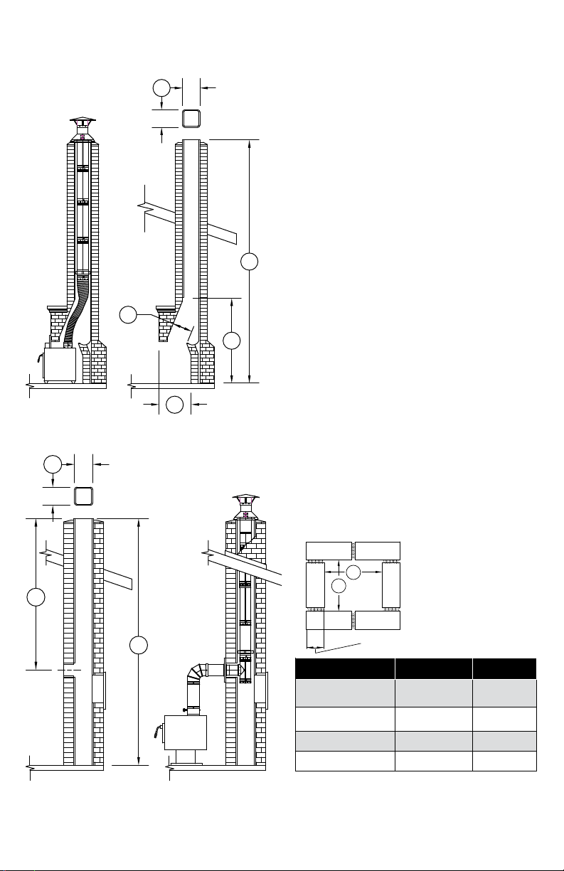
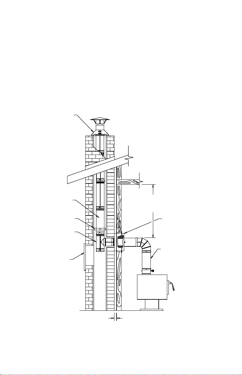
IMPORTANT MEASUREMENTS
1
1. Flue size I.D.:
• _____________________
2. Opening of replace:
• height _____________
• width ______________
• depth ______________
4
• length______________
• width ______________
3. Damper opening:
3
6
4. Total chimney and replace height:
• ___________________
5. Total chimney height to tee opening:
2
Figure 1
1
• ___________________
6. Height to rst tile:
• ___________________
7. Height of appliance:
• ___________________
A
5
4
B
3 1/2”
TYPE A B
6" ROUND 7" 7"
8" ROUND 9" 9"
6" OVAL 8" 5 1/2"
8" OVAL 11 5 1/2" - 6"
Figure 2
Figure 3
4
Page 5
APPLICATION AND LISTING
DuraLiner is a double-wall, insulated allfuel reliner for masonry chimneys, used for
natural draft venting of gas, liquid and solid
fuel appliances. DuraLiner is listed to UL
1777 and ULC S635 under listing le number
MH14420, where maximum continuous
ue gas outlet temperatures do not exceed
1000°F/538°C (UL 1777) or 1200°F/650°C
(ULC S635). DuraLiner is approved for
installation with zero clearance between
the liner and masonry, plus zero clearance
between the masonry and combustibles.
When the Transition Anchor Plate is used,
Round DuraLiner pipe can be coupled to a
Duravent factory built 103HT chimney system
at the end of a masonry enclosure.
GENERAL INSTALLATION
INSTRUCTIONS
Follow both these and the appliance manufacturer’s instructions and manual for maximum
efciency and safety. Connect only one ue
liner per appliance. DO NOT mix or match
with other products or improvise solutions(You may void warranties). DO NOT modify
parts.
Contact your local building ofcial or re
department regarding permits, restrictions,
and installation inspection in your area. Have
a professional installer thoroughly inspect (to
code requirements) and clean the existing
masonry ue of tar glaze creosote before
relining. The chimney should be checked
for cracked, loose or missing bricks, mortar,
or other materials that could inhibit correct
installation of the liner system. Make
necessary repairs prior to starting install.
Do not place insulation or other materials
other than specied in these instructions
around the liner or in required air spaces.
Determine if your setup is an open hearth
(Fig.1) or wall breach installation (Fig.2). Also
determine the available size of your chimney
and the corresponding allowable DuraLiner
size. (Fig.3)
• If you have an open hearth setup, verify
your ue size, and the replace opening
and depth before you purchase your
appliance and reliner.
• If you have a wall breach tee installation
setup, verify your ue size and chimney
height from tee, before you purchase your
appliance and reliner.
DuraLiner shall be sized not less than that
specied in the appliance manufacturer’s
instructions. Vent sizing is especially important
in areas with low ambient temps and low
temp ue products. Determine the required
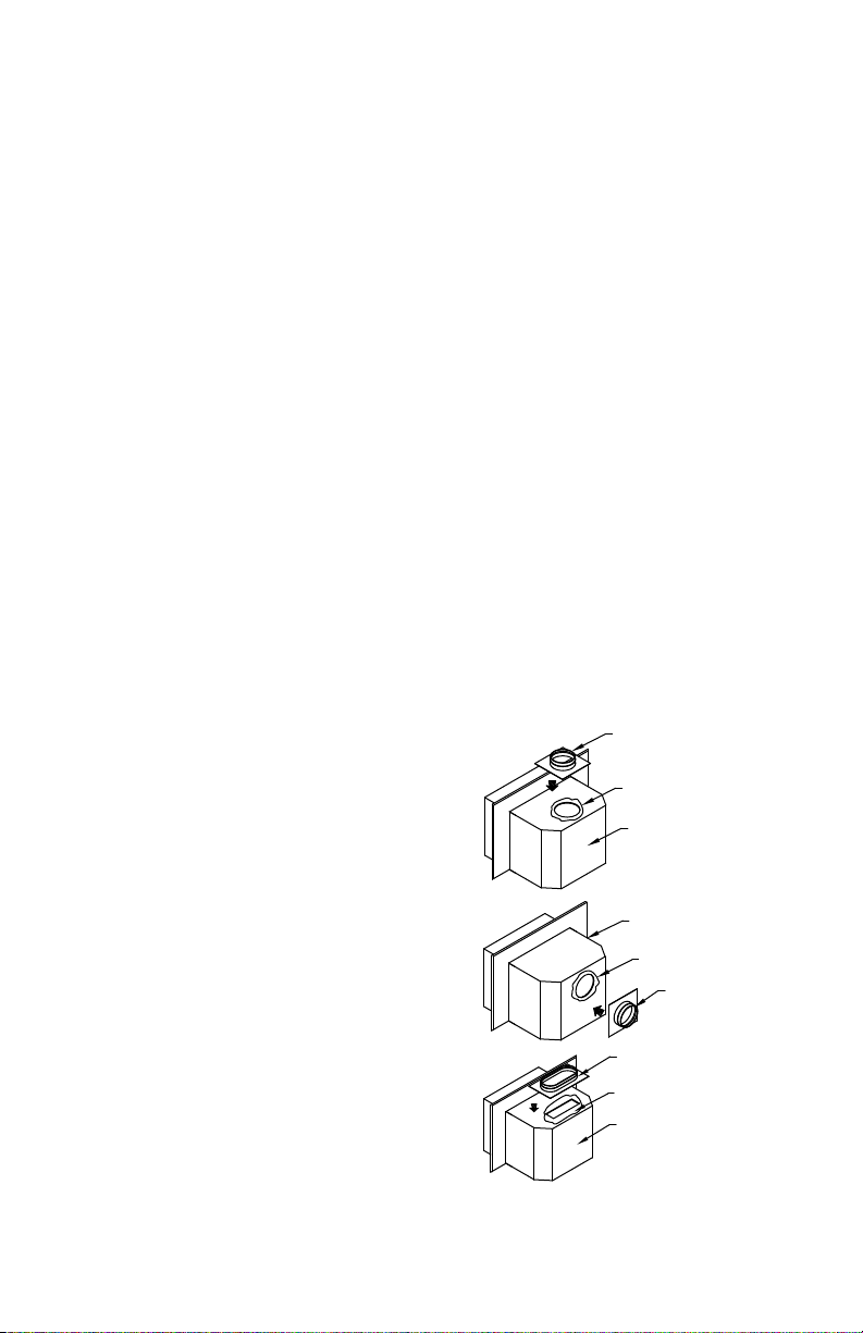
size of DuraLiner and the correct Appliance
Connector (follow appliance manufacturer’s
recommendations). There are three different
types of appliances connections (Fig.4).
ROUND CONNECTOR
HIGH TEMPERATURE
SEALANT
APPLIANCE
APPLIANCE INSERT
HIGH TEMPERATURE
SEALANT
ROUND CONNECTOR
OVAL CONNECTOR
HIGH TEMPERATURE
SEALANT
APPLIANCE
Figure 4
5
Page 6
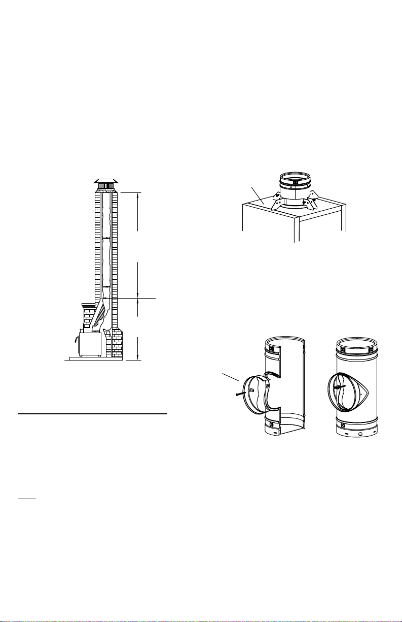
From the appliance up through the damper
area to the rst ue tile, it is not mandatory
to insulate ex pipe. Above the rst ue
tile, ex pipe must be insulated. NOTE:
For improved draft and re safety, we
recommend ALL ex pipes be insulated
(Fig.5)- (See "Installing Insulation" later in
these instructions for detail).
in this document). Note: If using an Oval pipe,
this will need to be inserted prior to the plate.
DuraLiner is supported from the top, and the
top plate is designed to support the weight of
a relining system up to 50 feet (the minimum
height of the system must be at least 10-feet to
ensure proper drafting performance). (Fig.6)
ZERO CLEARANCE TO
MASONRY IN THIS AREA
IF INSULATION SLEEVE
IS USED
FLUE TILE
STARTS
AT THIS
POINT
ZERO CLEARANCE TO
MASONRY IN THIS AREA
Figure 5
OPEN HEARTH INSTALL (Fig.1)
STEP ONE: Clear the ue of obstructions
for Duraliner to be installed. If applicable,
remove the existing damper from your
replace (not needed) and in some cases part
of the smoke shelf to allow DuraLiner to pass
through this area freely.
Note: DuraLiner ex pipe is available in both
round and oval shapes to ease installation.
STEP TWO: Prepare the top of the Masonry
chimney and install the top plate assembly
(Reference "Extend-A-Cap" instructions later
TOP PLATE
TOP SUPPORT CLAMP
ASSEMBLY
Figure 6
STEP THREE: Start with your rst component
(ex pipe, rigid pipe, or tee). If a tee is used,
the branch may be removed for installation
(Fig.7).
REMOVEABLE
BRANCH AND
HARDWARE
Figure 7
DuraLiner pipe (ex and rigid) has male and
female connectors with (4) pre-punched holes
and slots that line up and are connected with
stainless steel pop rivets (Fig.8). Do not use
screws. When connecting sections of ex
pipe, it is necessary to rst align the holes
with the slots, and then drill through the ex
6
Page 7

pipe with a 5/32” (4 mm) diameter twist drill
bit. Next, install the pop rivets. Drilling is
not needed to connect sections of rigid pipe.
Connect rst rigid section of DuraLiner on
top of ex section with (4) stainless steel pop
rivets.
Note: For insulating DuraLiner Flex, refer to
the "Insulating Flex" Instruction section later in
this document.
RIVET PIPE
SECTIONS
Connector ts on top vented appliances with
oval or rectangular openings.
STEP FIVE: Connect appliance to DuraLiner.
(Fig.9)
FLEX PIPE
STOVE CONNECTOR
POP RIVET OR
SCREW FLEX PIPE TO
STOVE CONNECTOR
1/2"
Figure 8
After pipe is riveted together, lower through
the Top Plate and clamp the pipe to support
(Fig.6). Attach next pipe section- Alternately
tighten and loosen the Top Plate clamp
assembly to hold and lower the pipe sections.
Repeat until the ex section reaches the
smoke shelf area. As the pipe is being
lowered down, bend the ex pipe to t through
the damper area. Lower DuraLiner to nal
position.
STEP FOUR: Connect appropriate DuraLiner
adapter to appliance (Fig.4). The DuraLiner
round Appliance Connector ts either a top
vented or rear vented round ue appliance.
Place the proper sized connector over the ue
exit and mark on the appliance the locations of
the holes where the connector will be attached.
Drill and tap hole in top or rear of appliance
or use self tapping screws. Before attaching
permanently, put a bead of high temperature
sealant between appliance connector and
insert. The DuraLiner oval appliance
Figure 9
FLEX PIPE
OVAL OR
ROUND
STOVE
CONNECTOR
RIGID TEE OVAL OR
ROUND
ADJUSTABLE SLEEVE (MIN.
OVERLAP 2")
Figure 10
Note: If you have a round ue outlet on your
appliance, and you have used Oval Flex or
Oval-To-Round ex through the damper area,
a Round-To-Oval ex piece or adapter will be
needed for the appliance connection.
If appliance has a round rear exit, align tee
with exit of appliance. An adjustable sleeve
7
Page 8

can be used to connect appliance to the tee
using the pre-formed buttons for connection.
The buttons snap into the branch ring. Slide
appliance into proper position. Secure
Adjustable Sleeve in nal position with sheet
metal screws. Rear ue exit should look like
Fig.10.
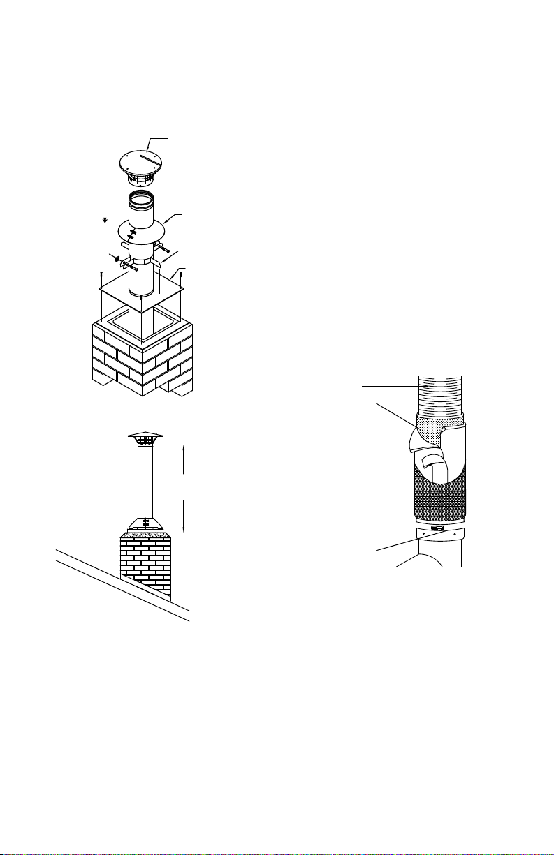
STEP SIX: Complete "Extend-A-Cap"
termination. (Reference "Extend-A-Cap"
instructions later in this document)
Note: National Fire Protection Association
standard #211 states; “Chimneys shall extend
at least three feet above the highest point where
they pass through roof of a building and at least
two feet higher than any portion of a building
within ten feet.” (Fig.11)
2 FEET MIN. ABOVE
POINT OF ROOF WITHIN
10 FEET
3 FEET MIN.
FROM ROOF
PENETRATION
10 FEET
Figure 11
WALL BREACHING (Fig.2)
There are two types of wall breaching:
- Masonry
- Masonry and Combustible Wall
(Note: Wall penetration assemblies shall not be
located directly behind a heating appliance.)
clearance to the ceiling for single wall pipe
is 18", and for DuraVent Close Clearance
Connector (DVL) Pipe, 8" (Fig.12).
COMBUSTIBLE
CLEARANCES:
18" SINGLE WALL PIPE
8" DURAVENT DVL PIPE
ACCESS DOOR
FOR CLEANOUT
Figure 12
Using the center mark punched into the
masonry, inscribe a circle of 3- 1/4 inch radius
(6-1/2 inch diameter), or 4-1/4 inch radius
(8-1/2 inch diameter), depending upon whether
6 inch or 8 inch Dura-Liner Pipe is used.
Remove bricks as necessary to approximate a
circle (Fig.14). Smooth out the circumference
of the hole with high-temperature grout or
mortar.
Follow "OPEN HEARTH INSTALLATION"
instructions for installation of DuraLiner pipe
in masonry. The end of the DuraLiner pipe
should have a "Tee" for the wall breaching, and
will be lowered to the masonry breach.
Masonry Breaching
STEP ONE: If no hole exists in the masonry,
mark the center point for the location of
penetration. Before cutting or drilling,
check the clearance between the top of the
connecting pipe to the ceiling. The minimum
8
STEP TWO: As the DuraLiner rigid pipe is
being lowered into nal position, line up the
branch of the Tee with hole in the masonry
chimney wall. (Fig. 13). Attach Tee branch to
Tee body (Fig.7).
Page 9

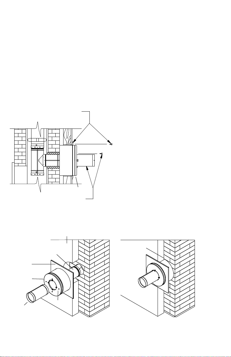
STEP THREE: Using DuraVent's Masonry
Thimble with Slip Connector, connect slip
connector to Tee Branch with the preformed buttons. Slide Masonry thimble to
slip connector and attach black trim plate to
masonry surface using screws. (Fig.13)
MASONRY
THIMBLE
TEE
ANCHOR
SCREWS
ACCESS
SLIP CONNECTOR
FROM MASONRY
THIMBLE
DOOR FOR
CLEANOUT
Figure 13
STEP FOUR:
Finish installation to appliance using connector
pipe, maintaining required clearances.
Combustible Wall and Masonry
(See completed installation in Fig.15)
STEP ONE: If no hole exists in the masonry,
mark the center point for the location of
penetration into the combustible wall. Before
cutting or drilling, check the clearance between
the top of the connecting pipe to the ceiling,
as shown in Fig.12, Fig.15. The minimum
clearance to the ceiling for single wall pipe is
18", and for DuraVent DVL Connector Pipe, 8".
Scribe a circle from the center point on the wall
with a 7-1/4 inch radius (14-1/2 inch diameter)
(Fig.14). This is the size of the hole required
for the Wall Pass-Through to t through the
combustible wall. Again, before cutting this
hole, check the clearance from the top of the
Connector Pipe to the ceiling.
STEP TWO: If the minimum clearance to the
combustible ceiling is met, then drill a 3/8 inch
diameter hole through the combustible wall, at
the center of the 14-1/2 inch circle you have
inscribed. With a punch, mark the center on
the masonry behind the wall. Cut the 14-1/2
inch diameter hole in the wall. If it is necessary
to cut through studs, additional framing should
be installed to maintain the structural integrity
of the wall (Fig.14).
STEP THREE: Using the center mark
14 1/2
STUDS ON 16-INCH CENTERS
FRONT VIEW
6 1/2 OR 8 1/2 DIA.
GROUT
SIDE VIEW
Figure 14
punched into the masonry, inscribe a circle
of 3- 1/4 inch radius (6-1/2 inch diameter),
or 4-1/4 inch radius (8-1/2 inch diameter),
depending upon whether 6 inch or 8 inch
Dura-Liner Pipe is used. Remove bricks as
necessary to approximate a circle. Smooth
out the circumference of the hole with hightemperature grout or mortar. Maintain the
concentricity of this hole with the hole cut in
the combustible wall. The completed hole
should look like (Fig.14).
9
Page 10
STEP FOUR: Push the Adjustable Sleeve from
the Wall Pass Through into the branch of the
tee. Connect Adjustable Sleeve to Tee Branch
with the pre-formed buttons. Recommended
to grout in place with a high temperature grout
(Fig.15, Fig.16).
STEP FIVE: Slide the Wall Pass-Through
through the square trim plate and into the
EXTEND-A-CAP ASSEMBLY
Adjustable Sleeve until the base of the Wall
Pass Through is ush against the masonry
(Fig.17) NOTE: The Wall Pass Through
must protrude a minimum of 2" into the
room (Fig.16).
Attach the 10" Long Rigid Pipe Section to the
front of the Wall Pass Through with four sheet
screws through the L-brackets (Fig.15, Fig.16)
Position the appliance, at it’s nal location.
10
RIGID PIPE
SPACER
RIGID TEE
ACCESS DOOR
(FOR CLEANING)
1 INCH AIR GAP
Figure 15
MINIMUM
CLEARANCE:
(NOTE BELOW)
COMBUSTIBLE WALL
THIMBLE ASSEMBLY
PIPE (AS REQUIRED)
NOTE: MINIMUM CLEARANCE FOR
SINGLE WALL STOVEPIPE IS 18 INCHES.
FOR DVL PIPE, THE MINIMUM IS 8
INCHES.
Page 11
Check the appliance manufacturer’s
ASSEMBLY)
installation instructions to ensure proper
positioning with relation to combustibles.
EXTEND-A-CAP INSTALLATION
The cap may be installed on both round and
oval rigid systems.
Complete the installation with Connector Pipe
Sections and Fittings as required. Inspect the
completed job to ensure it is done in a careful
and workman-like manner.
TRIM COLLAR
AND SCREWS
(COMPONENTS OF
WALL PASS-THRU
ASSEMBLY)
2" INTO THE ROOM
RIGID PIPE
AND SCREWS
(COMPONENTS OF
WALL PASS-THRU
Figure 16
STEP ONE: Center the base plate on the top
of the masonry chimney (Fig.18). Trim to t
the chimney as required. Use non-hardening
sealant to seal the base plate to the masonry
chimney, but this can be done after the liner
has been lowered into place. Anchors or
screws are recommended but not required, as
the base plate will ultimately be supporting the
entire weight of the installation.
STEP TWO: Assemble and position the clamp
assembly on top of the base (Fig.6, Fig.18).
Adjust the bolts on the clamp assembly so that
pipe sections will just pass through the clamp.
STEP THREE: Once the desired length of
liner has been achieved, tighten the clamp
assembly bolts, until the system is rmly
supported by the base. There should not be a
Duraliner pipe joint above the clamp assembly.
Attach the storm collar, and seal with nonhardening silicone (500°F) sealant. Install Cap
to pipe, using #8 sheet metal screws. (Fig.19).
ADJUSTABLE
TRIM PLATE
INSULATED WALL
PASS THROUGH
10" LONG
RIGID PIPE SECTION
COMBUSTIBLE WALL
SLEEVE
HARDWARE
THROUGH AGAINST
Figure 17
WALL PASS
MASONRY
11
Page 12
Do not construct chases or other enclosures
around DuraLiner pipe sections which extend
above the masonry.
CAP AND SPARK
NOTE:
MOISTURE MUST NOT
ENTER THE LINER
SYSTEM!
ARRESTOR
STORM COLLAR
CLAMP
BASE
and trim the blanket so that the ex end rings
are exposed. Wrap the insulation around the
liner lengthwise and trim it so that a butt joint
is formed. Seal the joint with aluminum foil
tape. Spray adhesive may be used to hold the
blanket in place until it can be secured with
the foil tape. A minimum of 1/2" of insulation is
required. Install ProMesh protective wire mesh
over the blanket(s). The ProMesh is used to
protect the ProFoil insulation as the liner is
lowered into the chimney. Slip the ProMesh
over the insulated liner and secure one end
with a stainless steel band clamp. Pull the
ProMesh towards the other end of the liner so
that it tightens snugly around the insulation,
then trim off the excess. Secure this end with a
stainless steel band clamp or alum tape.
LINER
Figure 18
NO DURALINER PIPE
JOINT ABOVE CLAMP
Figure 19
INSULATING FLEX
Duravent requires ex be insulated above
the rst Masonry ue tile, and strongly
recommends ALL Flex pipe be insulated.
Method #1: PROFOIL (Fig.20)
Roll out the insulation blanket on a clean
surface, foil face down. Lay the ex liner on top
12
1/2" OF
PROFOIL
ALUMINUM
TAPE
PROMESH
CLAMP
Figure 20
Method #2: INSULATION SLEEVE
Slip the Insulation Sleeve over the ex
pipe. Install the bottom insulation sleeve
clamp, and push the top of the sleeve down
4"-6". Position clamps so the nut and bolt
connections are pointing towards the corner of
a rectangular chimney.
Page 13
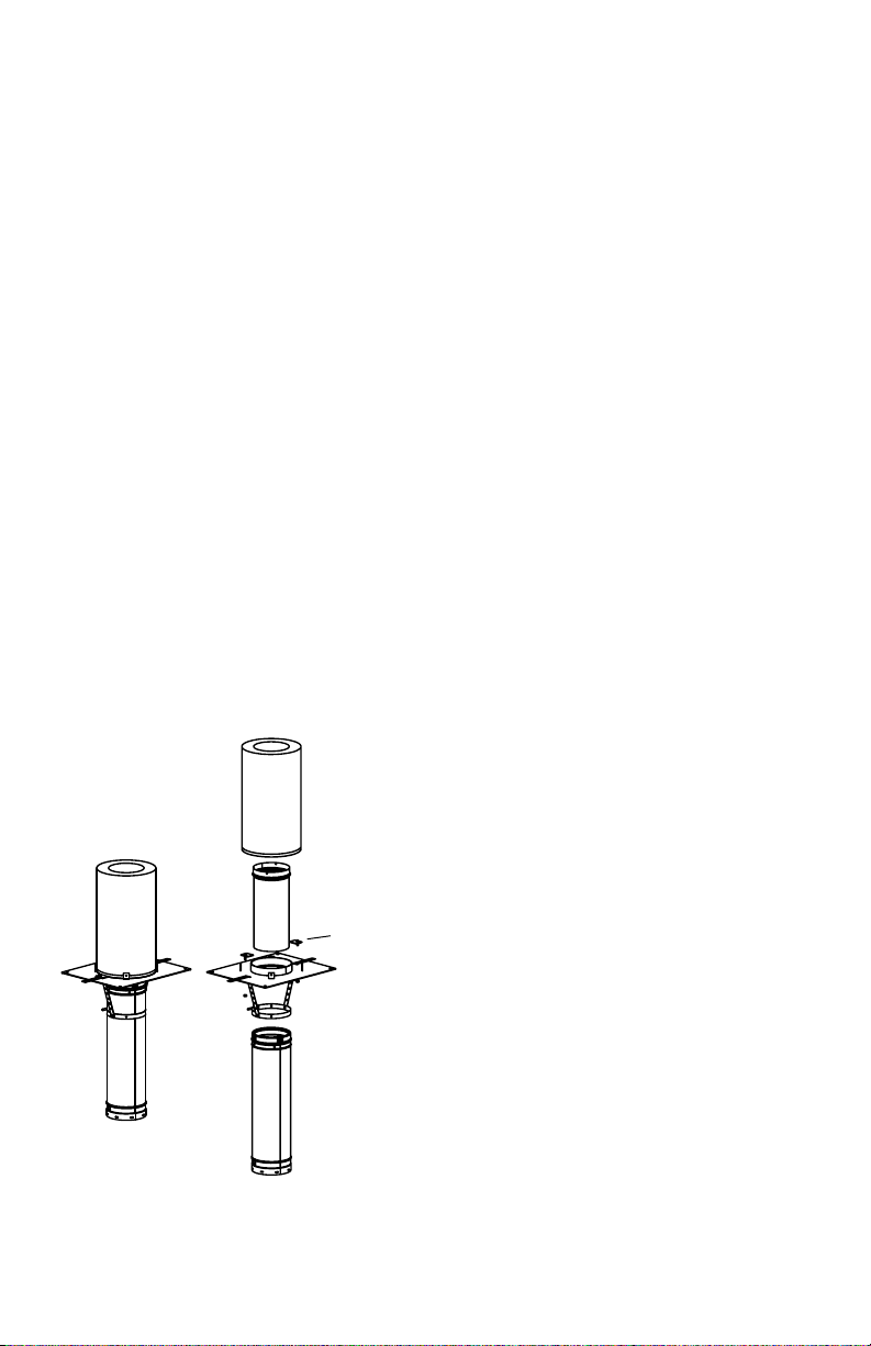
TRANSITION ANCHOR PLATE
Ensure Round DuraLiner Pipe section will be
within 12" of the top of the masonry. Secure
Hanger to the top piece of DuraLiner pipe.
Lower the Transition Anchor Plate (T.A.P) and
allow the legs of the Hanger to slide through
the oval slots in the T.A.P. Attach T.A.P. to the
top of the existing masonry with eld supplied
hardware. If desired, a bead of 1000°F stove
cement may be used as a gasket for this
surface. Pull hanger straps tight, fold down,
and bolt to plate using provided hardware.
Once the hanger is afxed to the T.A.P., insert
slip connector down through the T.A.P. and into
DuraLiner pipe (Fig.21). Place Chimney onto
Transition Anchor Plate and afx with screws
to the brackets as shown.
Note: If using DuraPlus Chimney and
enclosing in a chase, the DuraPlus Starter
section MUST be the rst section of Chimney
used at the Transition Anchor Plate.
CHIMNEY
TRANSITION ANCHOR PLATE
ASSEMBLY
SLIP CONNECTOR
HOLD DOWN
BRACKETS
TRANSITION
ANCHOR PLATE
HANGER
DURALINER
Figure 21
DURALINER MAINTENANCE
- Creosote and Soot-Formation and Need
for Removal: When wood is burned slowly,
it produces tar and other organic vapors,
which combine with expelled moisture to
form creosote. The creosote vapors may
condense on the inside of the chimney liner
during slow-burning ring periods. As a result,
creosote residue accumulates on the chimney
liner. When ignited, this creosote makes an
extremely hot re.
- The chimney liner system should be
inspected at least once every two months
during the heating season to determine if a
creosote or soot buildup (3mm or more) has
occurred. The spark arrestor screen should
be checked more frequently. If creosote or
soot has accumulated, it should be removed to
reduce the risk of a chimney re.
1. Access – Chimney liners must be installed
to provide access for inspection and cleaning.
2. How to Clean – Recommend to have
your chimney liner cleaned by a professional
certied chimney sweep. Use a plastic, wood,
or exible steel or wire brush- do not mar the
stainless steel liner surface. To remove the
chimney cap for cleaning, unscrew the four
screws that attach the cap’s support legs to the
cap base.
3. Coal – Clean the chimney thoroughly within
48 hours of shutting down the appliance for the
season. Check the chimney for acid corrosion
regularly.
4. No Chemical Cleaners – Do not use
chemical chimney cleaners. Their use does
not eliminate the need for mechanical cleaning
and they may be highly corrosive.
6. In case of Fire – If a ue re occurs, close
all appliance draft openings and call your Fire
Department. Do not use the chimney again
until it is inspected for possible damage.
13
Page 14

INSTALLATION NOTES:
14
Page 15

INSTALLATION NOTES:
15
Page 16

M&G DURAVENT LIMITED LIFETIME WARRANTY
M&G DuraVent, Inc. (“DuraVent”) provides this limited lifetime warranty for all of its products with the exception of Ventinox® (lifetime), and
PolyPro® (ten years). Subject to the limitations set forth below, DuraVent warrants that its products will be free from defects in material or
manufacturing, if properly installed, maintained and used. DuraVent products are fully warranted if installed only by a professional installer.
This Warranty is transferable from the original homeowner to the buyer of the home. This warranty does not cover normal wear and tear, smoke
damage or damage caused by chimney res, acts of God, or any product that was: (1) purchased other than from an authorized DuraVent
dealer, retailer or distributor; (2) modied or altered; (3) improperly serviced, inspected or cleaned; or (4) subject to negligence or any use not
in accordance with the installation instructions included with the product as determined by DuraVent. Installation instructions are available
online at www.duravent.com under Support/Literature and through our Customer Service Department 800-835-4429 or customerservice@
duravent.com. This limited lifetime warranty applies only to parts manufactured by DuraVent.
DuraVent provides the following warranties for its products: One Hundred Percent (100%) MSRP 15 years from the date of purchase, and Fifty
Percent (50%) thereafter, except for the following limitations on: all Termination Caps and DuraBlack® are warranted at One Hundred Percent
(100%) for ve years.
All warranty obligations of DuraVent shall be limited to repair or replacement of the defective product pursuant to the terms and conditions
applicable to each product line. These remedies shall constitute DuraVent’s sole obligation and sole remedy under this warranty. This warranty
provides no cash surrender value. The terms and conditions of this warranty may not be modied, altered or waived by any action, inaction or
representation, whether oral or in writing, except upon the express, written authority of an executive ocer of DuraVent.
Corn, bio-fuels, driftwood or other wood containing salt, preservative-treated lumber, plastic and household trash or garbage, or wood pellets
containing such materials must not be burned in the appliance or replace. In case of a chimney re, the chimney must be inspected and
approved by a certied Chimney Sweep before reuse. After each annual inspection, maintenance, and cleaning, the certied Chimney Sweep
must ll out and date the appropriate section of the warranty card provided with the chimney liner.
LIMITATIONS ON INTERNET SALES: Notwithstanding any other terms or conditions of this Limited Lifetime Warranty, DuraVent provides no
warranty for the following specic products if such products are not installed by a qualied professional installer: DuraTech®, DuraPlus HTC®,
DuraChimney® II, PelletVent Pro®, DirectVent Pro®, FasNSeal®, FasNSeal® W2, FasNSeal® Flex, and PolyPro®, and M&G DuraVent’s relining
products including DuraLiner®, DuraFlex® (SW, Pro, 316, 304), and Ventinox®. For purposes of this warranty, a trained professional installer is
dened as one of the following: licensed contractors with prior chimney installation experience, CSIA Certied Chimney Sweeps, NFI Certied
Specialists, or WETT Certied Professionals.
DuraVent must be notied and given the opportunity to inspect defective product prior to replacement under the terms of this limited lifetime
warranty. All warranty claims must be submitted with proof of purchase. Labor and installation costs are not covered under this warranty. To
obtain warranty service contact: DuraVent Warranty Service, 877 Cotting Ct., Vacaville CA 95688, or call 800-835-4429.
WHERE LAWFUL, DURAVENT DISCLAIMS ALL OTHER WARRANTIES, INCLUDING BUT NOT LIMITED TO IMPLIED WARRANTIES OF
MERCHANTABILITY AND FITNESS FOR A PARTICULAR PURPOSE. IN NO EVENT WILL DURAVENT BE LIABLE FOR INCIDENTAL, CONSEQUENTIAL,
PUNITIVE OR SPECIAL DAMAGES OR DIRECT OR INDIRECT LOSS OF ANY KIND, INCLUDING BUT NOT LIMITED TO PROPERTY DAMAGE AND
PERSONAL INJURY. DURAVENT’S ENTIRE LIABILITY IS LIMITED TO THE PURCHASE PRICE OF THIS PRODUCT. SOME STATES DO NOT ALLOW
LIMITATIONS ON IMPLIED WARRANTIES, OR THE EXCLUSION OR LIMITATION OF INCIDENTAL OR CONSEQUENTIAL DAMAGES, SO THE ABOVE
LIMITATIONS AND EXCLUSIONS MAY NOT APPLY TO YOU. THIS LIMITED WARRANTY GIVES YOU SPECIFIC LEGAL RIGHTS, AND YOU MAY ALSO
HAVE OTHER RIGHTS THAT VARY FROM STATE TO STATE.
For the most up-to-date installation instructions, see
www. duravent.com
REV 3.22.2012
Manufactured in Vacaville CA and Albany NY
Customer Service Support 800-835-4429 707-446-4740 FAX www.duravent.com
DuraLiner is a registered trademark of the M&G DuraVent, Inc.
All rights reserved. Made in the USA. M&G DuraVent is a member of M&G Group. ©2012
L402 09/2012
 Loading...