

Page 1

SUBMITTAL RECORD
UL 1978 - Grease Duct
Professional Series
Kitchen Ventilation
DCL Single Wall
DAS1 1-inch Air Insulated
DIS1 1-inch Insulated (AES WOOL)
DIS2 2-inch Insulated (AES WOOL)
DIS4 4-inch Insulated (AES WOOL)
DIS3Z 3-inch Insulated (AES WOOL)
SUBMITTAL RECORD
PREPARED FOR:
REFERENCE:
LOCATION:
CONTACT:
TELEPHONE: FAX:
EMAIL:
PREPARED BY:
Material Selection
FLUE (INNER WALL) CASING (OUTER WALL)
304 304
316 441
GALVALUME
DV-PRO REV. 1 09-26-17
Listed to standards:
UL 1978
UL 2221 - DIS3Z Only
CAN/ULC S662
Reference to the Installation Instructions will enable you to obtain a
safe, efficient and dependable installation of this vent system.
Do not alter or modify the components of this vent system under
any circumstances. Any modification or alteration of the vent system
or approved accessories, including but not limited to the appliance it
is connected to, may void the warranty, listings and approvals of this
system and could result in an unsafe and potentially dangerous
installation.
1
Page 2

Models: DCL, DAS1, DIS1,
UL 1978 - Grease Duct – All Models
5”- 36” ID
UL 2221 - Fire Resistant Enclosure DIS3Z ONLY
5”- 36” ID
ULC S662 - Grease Duct – All Models
5”- 36” ID
DIS2, DIS4, DIS3Z
SECTION A – CODE COMPLIANCE
UNDERWRITERS LABORATORIES
LISTINGS
Model D C L ( s i n g l e w a l l ) DAS1 ( 1 -i n ch air) , D I S 1 , DIS2, D IS4, D I S 3 Z
(Double wall, AES Insulation)
ULC S662 - Grease Duct
These requirements cover factory-built grease ducts and
grease duct assemblies that are intended to be installed as
alternatives to the grease ducts constructed of all welded 1.37
mm carbon steel or 1.09 mm stainless steel required by ULC-
S650, Standard
Ventilation and Fire Suppression Systems for Commercial
and Institutional Cooking Equipment. Grease ducts
by these requirements are intended to be installed in a fire
rated
enclosure when required by the provincial or territorial
regulations or bylaws, or in the absence of those
requirements by the National Building Code of Canada.
Grease duct assemblies that penetrate fire rated assemblies
which do not require the protection of a fire rated enclosure
are covered by the requirements contained in CAN/ULCS144,
Standard Method
Assemblies.
for the Installation and Performance of
of Fire R
esistance Test - Grease Duct
covered
COMPLIES TO THE FOLLOWING:
National Fire Protection Association (NFPA)
• Complies with NFPA 96 – “Standard for Ventilation
Control and Fire Protection of Commercial Cooking
Operations
International Code Congress (ICC)
• Complies with “International Mechanical Code” and
“International Building Code” if applicable to the
project or site
International Association of Plumbing and Mechanical
Officials (IAPMO)
• Complies with “Uniform Mechanical Code” if
applicable to the project or site
UL 1978 Grease Duct Listing:
DuraVents Model DCL, DAS1, DIS1, DIS2, DIS4
and DIS3Z are listed for continuous temperatures of 500°F
and intermittent temperatures of up to 2000°F, and are
ideally suited for use in commercial cooking installations
for the removal of smoke and grease laden vapors (Type I
or Type II kitchen exhaust hood). Grease duct system
size and capacity information may be obtained from the ”
ASHRAE Handbook – Fundamentals ” or from the ”
Air Pollution Engineering Manual ” of the ” US
Environmental Protection Agency. ”
UL 2221 Listing:
DuraVents Model DIS3Z is classified in accordance with
UL 2221 (Tests of Fire Resistive Duct Enclosure
Assemblies) as an alternate to a 2-Hr. fire resistive shaft
enclosure with a minimum zero clearance to combustibles
(sizes 5” to 36” diameters). Model DIS3Z has been
evaluated in accordance with the requirements for duct
enclosure Condition A.
MIXING PARTS
Model DCL, DAS1, DIS1, DIS2, DIS4 and DIS3Z
listed to UL 1978 may be intermixed within a system,
assuming proper clearances are maintained for
respective components. When penetrating a roof,
appropriate roof penetration components must be
used.
Do not use Model DCL to penetrate through a
wall, floor or roof.
2
Page 3

SECTION B
Clearance to Combustible (Unenclosed Surrounding)
Grease Duct UL1978 (500°F / 260°C)
Ø
DAS1
DIS1
DIS2 and DIS4
DIS3Z
5 4 2 1 0
18 6 5 2 1
0
18 7 5 2 1
0
18
8 5 2 1 0
18
9 5 2 1 0
18
10 5 2 1 0
18
11 5 2 1 0
18
12 6 2 1 0
18
13 6 2 1 0
18
14 6 2 1 0
18
16 6 3 1 0
18
18 7 3 2 0
18
20 7 3 2 0
18
22 7 3 2 0
18
24 8 3 2 0
18
26 8 4 2 0
18
28 8 4 2 0
18
30 9 4 2 0
18
32 9 4 3 0
18
34 9 4 3 0
18
36
10 5 3
0
18
– GENERAL INFORMATION
PART NUMBERS
This submittal identifies major model parts by name and part
number.
Material Code Designation:
B = Type 316 Stainless Steel (SS)
C = Type 304 Stainless Steel (SS)
E = Aluminum Zinc Coating (GALVALUME)
K = Type 441 Stainless Steel (SS)
Example:
DAS1 – 36” length with inside diameter of 14” made of SS 316
inner flue and SS 304 outer casing; Code = DAS1- 14 L36 BC
DAS1 14 L36 BC
Model Dia. Part Material
Model DCL) or the Outer Band BSE (for Model
DAS1, DIS1, DIS2, DIS4 and DIS3Z). See Figure 1
for the clearance distance.
For fire resistive non-combustible enclosure construction,
maintain clearance as required for installation access for
inspection or per local code. In buildings, more than one story
in height and in one-story buildings where the roof-ceiling
assembly is required to have a
fire resistance rating, the duct must be enclosed in a
continuous enclosure from the lowest fire-rated ceiling or floor,
through any concealed spaces, to or through the roof to
maintain the integrity of the fire separations required by the
applicable building code provisions. If the building is less than
4 stories in height, the enclosure shall have a fire resistance
rating of not less than 1 hour. If the building is 4 stories or more
in height, the enclosure shall have a fire resistance rating not
less than 2 hours.
DuraVent Models DCL, DAS1, DIS1, DIS2, DIS4 and DIS3Z
chimneys may penetrate a combustible floor, wall, or roof using
the appropriate parts and openings sizes.
DIS2 - 30° elbow with inside diameter 22” made of SS 304
inner flue and Galvalume outer casing; Code = DIS2- 22 E30
CE
DIS2 22 E30 CE
Model Dia. Part Material
DCL – wall support for 8” diameter grease duct made
of Galvalume; Code = DCL- 8 WS E
DCL 8 WS E
Model Dia. Part Material
Use only factory supplied components. Failure to
do so will void the certification and the warranty of
the chimney system.
EFFECTIVE LENGTH AND MATERIAL
THICKNESS
The effective length is the length of the part when it is
assembled.
Effective Length Thickness for 5” to 36” diameters
L36 = 36-1/8” inner wall = 0.035”
L24 = 24-1/8” outer wall = 0.024”
L18 = 17-5/8”
L12 = 11-5/8”
NOTE: Model DIS3Z is equivalent to a 2-Hr fire rated
grease duct enclosure system.
NOTE: Do not completely enclose the chimney with
combustible materials.
In the case of a fire rated enclosure made of non-combustible
or limited combustible construction, the minimum
for Model
Model DIS3Z can be used for either combustible or noncombustible surroundings. When installed in an open room
where enclosure is not required, the duct may be located at a
minimum clearance to adjacent combustible walls
DCL is 6” or as required by local code.
clearance
(from the outer band)
DCL
CLEARANCE TO COMBUSTIBLE NON FIRE RATED UL 1978 LISTING
APPLICATION
Model DAS1, DIS1, DIS2, DIS4 and DIS3Z can be used for
either combustible or non-combustible surroundings. When
installed in an open room where enclosure is not required, the
chimney may be located at a minimum clearance to adjacent
combustible walls in accordance with Table 1. The chimney
may be located in corners formed by two combustible
constructions (walls, floor, ceiling, supports, etc.)
NOTE: The clearance distance with the wall is the
distance between the wall and the Inner V-Band (for
Table 1: Clearance to Combustible
Dimensions are in inches
NOTE: Clearance to non-combustible is 0” for all models / all
diameters
3
Page 4
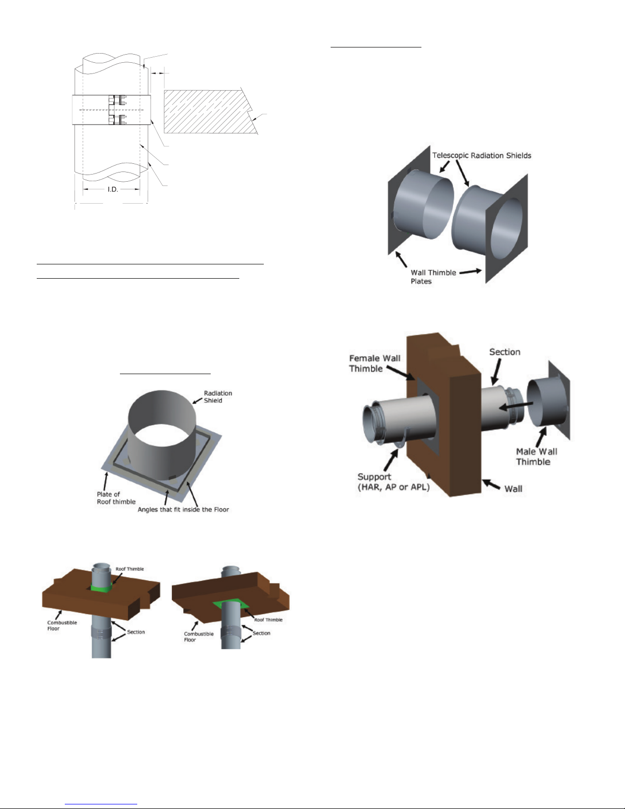
Figure 01: Detail of Clearance to Combustible
!$& %"!'#'"#'#
'
&%#'!''
'
"#'
'
&''DCL, DAS1, DIS1, DIS2, DIS4,
DIS
3Z
''
'
DAS1, DIS1, DIS2, DIS4,
DIS
3Z
DIS1, DAS1, DIS2, DIS4, DIS3Z
UL 1978 LISTING APPLICATION WALL,
FLOOR AND ROOF PENETRATION
A chimney that must penetrate through a wall, floor or roof
made of COMBUSTIBLE materials, must use a Wall Thimble
(WT) or Roof Thimble (RT). The minimum air space clearance
between the outer wall of the duct and the combustible
material of the wall, floor or roof must always be respected.
ROOF THIMBLE (RT)
WALL THIMBLE (RT)
The part consists of a roof thimble female half and a male roof
thimble that slide in each other to adjust wall thickness from 8”
to 12”. The minimum air space clearance between the outer
wall of the duct and the combustible material of the wall, floor
or roof must always be respected. The duct must be well
supported on both sides of the wall to prevent any load or
offset of the duct in the Wall Thimble.
Figure 4: Wall Thimble (WT)
Figure 2: Roof Thimble (RT)
Figure 3: Visualization Roof Thimble Installed
4
Figure 5: Visualization of Wall Thimble Installed
Page 5

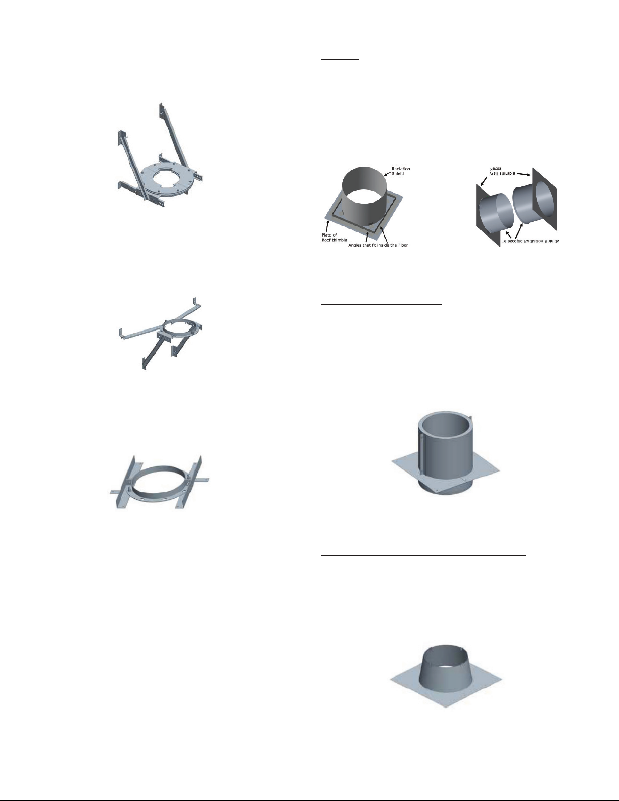
Minimum Square OPENING for NON-Fire Rated Floor / Wall /
Roof for different Models
Duct
Flue
Through
Through
(in.)
5 to 36
ID + 37 1/4”
ID + 1 1/4”
5
ID + 8 3/4”
6 to 11
ID + 10 3/4”
12 to 16
ID + 12 3/4”
18 to 22
ID + 14 3/4”
24 to 28
ID + 16 3/4”
30 to 34
ID + 18 3/4”
36
ID + 20 3/4”
5 to 13
ID + 4 3/4”
14 to 24
ID + 6 3/4”
26 to 34
ID + 8 3/4”
36
ID + 10 3/4”
5 to 16
ID + 2 3/4”
18 to 30
ID + 4 3/4”
32 to 36
ID + 6 3/4”
5 to 16
ID + 2 3/4”
18 to 30
ID + 4 3/4”
32 to 36
ID + 6 3/4”
5 to 9
10 to 36
CLEARANCE TO COMBUSTIBLE (from the outer band -
BSE)
DIS3Z – 5” TO 36”
O”
DAS1: 0 8 = 0A + 2
DIS1: 08 = 0A + 2
DIS2: 08 = 0A + 4
DIS4: 08 = 0 A + 8
C = 0 B + 3/4
D = C + (2 x Clearance)
See Table for
Opening Dimensions
Outer Band (BSE)
For Models DAS1, DIS1, DIS2, DIS4
Floor
INNER WALL
DCL, DAS1, DIS1, DIS2, DIS4)
OUTER WALL
( DAS1, DIS1, DIS2, DIS4 )
Insulation (Air or Fiber Wool)
Figure 6: Openings for through Floor / Wall / Roof Models
DAS1, DIS1, DIS2, DIS4 made of combustible material
Grease Duct – UL1978
CLEARANCE TO COMBUSTIBLE FIRE
RATED
UL 2221
Model DIS3Z is equivalent to a 2 – Hour fire
rated grease duct enclosure system.
DIS3Z is “0” inch clearance to combustible
Table 3: DIS3Z Clearance to Combustible
Model DIS3Z may penetrate a combustible floor, wall or roof
using the appropriate parts and opening sizes. Refer to the
installation instructions for detailed information.
Whenever the DIS3Z grease duct passes through a fire rated
wall or floor, a DIS3Z Ø TPFK must be used to maintain the
fire rating.
Fire resistance rating: 2 hours (F & T)
Model
Diameter Ø
(in.)
Combustible
Roof / Floor /
Wall (in.)
Non-Combustible
But NOT-FIRE-
RATED
Roof / Floor / Wall
DCL
DAS1
DIS1
DIS2
DIS4
DIS3Z
ID + 6 3/4” ID + 6 3/4”
ID + 2 3/4”
ID + 2 3/4”
ID + 4 3/4”
ID + 8 3/4”
Table 2: Openings for through Floor / Wall / Roof – NON-Fire-
Rated
Grease Duct – UL1978
FIRE RATED (2-HR) FLOOR PENETRATION
Fig. 7: Through Penetration Firestop fire-rated Floor
Penetration
NOTE:
Must use S-TPFS (Spec Seal Triple S Intumescent
Firestop Sealant – SSS100). Ordered separately
from DIS3ZØTPFK based on duct diameter. Refer
to table 4 for tube coverage.
5
Page 6

Expected number of tubes of S-TPFS per hole Through
a 2 – Hr. Fire Rated Wall or Floor
Inner Duct Diameter
Number of Tube per hole
5
2 – ¼
6
2 – ½
7
2 – ¾
8
2 – ¾
9 3 10
3 – ¼
11
3 – ¼
12
3 – ½
13
3 – ¾
14
3 – ¾
16
4 – ¼
18
4 – ½
20
5
22
5 – ¼
24
5 – ½
26 6 28
6 – ¼
30
6 – ½
32
7
34
7 – ¼
36
7 – ¾
FIRE RATED (2-HR) WALL PENETRATION
PROPER STORAGE
All chimney components should be stored in a dry place until
installed.
Sealant shall be stored in a location where it will not freeze.
PRODUCT WEIGHT DIS3Z
The average weight of the duct, per foot of length, can be
estimated using the following formula:
Fig. 8: Through a fire-rated Wall / requires 2 X DIS3ZØTPFK
Table 4: required number of tubes S-TPFS
SYSTEM SIZING
The Grease Duct system sizing should be done by an
experienced person familiar with duct sizing. Not following the
equipment manufacturer’s instructions may result in
inadequate duct performance and/or a violation of the
equipment manufacturer’s installation requirements.
EXTERIOR CORROSION PROTECTION
It is recommended to apply an exterior grade high heat paint to
any plate support, full/half angle rings, wall supports/guides,
aluminized outer duct wall (Galvalume) corrosion protection
against the elements. Rust-Oleum V200 series High Heat
Industrial Aerosol is an example for proper protection of these
components.
THERMAL EXPANSION CALCULATIONS
Thermal expansion under normal operating temperatures can
fatigue welds and joints causing leakage. To calculate the
thermal expansion, use the following formula:
[Length (ft.) / 100] X [Temperature Rise Degrees F / 100]
Example: [50’ / 100] X 75° / 100] = .375” Expansion
If the computed expansion between the fixed points is greater
than .375” DuraVent recommends an adjustable length be
installed.
SLOPE FOR GREASE DUCT
For DuraVent factory-built grease ducts listed to UL1978,
install at a duct slope not less than 1/16” unit vertical slope in
12 units of horizontal toward the hood or toward the grease
reservoir. When DuraVent grease duct listed to UL1978
exceed 75 feet in length, the slope shall not be less than 1/8”
unit vertical slope in 12 units horizontal. The minimum slope is
a result of tests and/or analysis performed by Underwriters
Laboratories, where factory-built grease duct was compared to
rectangular field-applied grease duct for performance of flow
characteristics. Consult with AHJ for acceptance of this
alternate method.
6
Page 7

SECTION C
TYPICAL INSTALLATION for GREASE
DUCT
Figure 9: Sample Installation for Grease Duct
7
Page 8

SEISMIC REQUIREMENTS
PRODUCT LABELS
In certain areas of the country, local codes contain
requirements to address Seismic risks. Seismic requirements
for chimneys and Grease Duct usually include specifications
for additional “sway bars” / bracing, or similar devices to help
stabilize the system in the event of an earthquake.
Specific guidelines (including spacing, location, size and
method of attachment of bracing / sway bars or other devices)
for addressing seismic requirements may vary depending upon
the adopted code, seismic zone, duct size, location in building,
etc. and are not within the scope of this submittal.
Consult with a design professional to determine compliance
options for these potentially complex requirements when this
product is to be installed in a building where these additional
requirements apply.
PRODUCT LABELS
8
Page 9

SUPPORT METHODS AND HEIGHT LIMITS
Height Limits for each Type of Support
(ft.)
4
1
1
2
2
5
Ø24 to Ø36
64
32
28
24
18
17
WARNING: Do not attached any supports to combustible constructions.
Maximum Vertical Spacing between any Guides/Supports and Maximum
Freestanding above the Roof
5
20’
8’ 6”
20’
7’ 3”
20’
6’ 6”
20’
6’
20’
6’ 6 20’
9’ 6”
20’
8’ 3”
20’
7’ 6”
20’
6’ 9”
20’
6’ 9” 7 20’
10’
20’
8’ 9”
20’
8’ 3”
20’
7’
20’
7’ 8 20’
11’
20’
9’
20’
8’ 6”
20’
7’ 3”
20’
7’ 3” 9 20’
11’ 6”
20’
9’ 3”
20’
8’ 9”
20’
7’ 6”
20’
7’ 6”
10
20’
12’
20’
9’ 6”
20’
9’
20’
7’ 9”
20’
7’ 9”
11
20’
12’ 6”
20’
9’ 9”
20’
9’ 3”
20’
8’
20’
8’
12
20’
13’
20’
10’
20’
9’ 6”
20’
8’ 3”
20’
8’ 3”
13
20’
13’ 6”
20’
10’ 3”
20’
9’ 9”
20’
8’ 6”
20’
8’ 6”
14
20’
14’
20’
10’ 6”
20’
10’
20’
9’
20’
9’
16
20’
14’ 6”
20’
11’
20’
10’ 6”
20’
9’ 6”
20’
9’ 6”
18
20’
15’
20’
11’ 6”
20’
11’
20’
10’
20’
10’
20
20’
15’
20’
12’
20’
11’ 6”
20’
10’ 9”
20’
10’ 9”
22
20’
15’
20’
12’ 3”
20’
11’ 9”
20’
11’
20’
11’
24
20’
15’
20’
12’ 9”
20’
12’ 3”
20’
11’ 6”
20’
11’ 6”
26
20’
15’
20’
13’
20’
12’ 6”
20’
12’
20’
12’
28
20’
15’
20’
13’ 6”
20’
13’
20’
12’ 3”
20’
12’ 3”
30
20’
15’
20’
13’ 9”
20’
13’ 6”
20’
12’ 9”
20’
12’ 9”
32
20’
15’
20’
14’ 3”
20’
13’ 9”
20’
13’ 3”
20’
13’ 3”
34
20’
15’
20’
14’ 6”
20’
14’ 3”
20’
13’ 6”
20’
13’ 6”
36
20’
15’
20’
15’
20’
14’ 6”
20’
13’ 9”
20’
13’ 9”
(ft.)
L
Half
Ring (HAR) /
Full Angle
Ring (FAR) /
Anchor
Support (AP) /
Anchor plate
with Length
(APL) /
Heavy Duty
Wall Guide
(HDWG)
1. Several support and guiding methods are used to
anchor a chimney against upward, downward and
angular displacement
2. These supports and guides used with thermal
expansion devices, prevent bending stresses on the
chimney elbows and joints
NOTE:
All the weight of the section must be supported by the
inner flue. Never support any chimney duct from the
outer wall.
* MVS = Maximum Vertical Spacing between two guides or support and guide in a vertical position.
** H = Maximum Freestanding Heigth above the roof. This limited height is due to wind loads.
Table 6: Support height limits
Parts
Flue
Diameter Ø
(in)
Ø5 to Ø22 26
Anchor Plate
(AP)
Anchor
Ø24 to Ø36 16
Ø5 to Ø22 28
Plate with
Length
(APL)
Base
supported
Tee
(T90 or
T45)
Wall Support
Ø24 to Ø36 17
Ø5 to Ø22 10
Ø24 to Ø36 63 32 27 23 17 16
Ø5 to Ø22 10
(WSHD)
Table 5: Support height limits
CL DA S1 / D IS1 DI S2 DI S4 DIS 3Z
in )
D
He igt h ( ft. ) Hei gth (ft .) Hei gth (f t.) He igt h ( ft. ) H eig th (ft .)
M
VS* H* * M VS* H* * M VS* H* * MV S* H* * M VS* H* *
Mo del
Fl ue Ø
(
Height
DSL DAS1 DIS1 DIS2 DIS4 DIS3Z
133 114 97 73 70
82 70 59 45 42
142 121 103 78 74
87 74 63 48 45
52 44 37 28 27
53 45 39 29 28
Figure 10: MVS and H limits
Maximum Horizontal Spacing between each Guides/Supports
Distance
Product
Flue
Diameter
Ø (in)
DS
DAS1 DIS1 DIS2 DIS4 DIS3Z
Angle
Ø5 to 12 23 23 19 16 12 12
Ø14 to 24 19 19 16 14 10 10
Ø26 to 36 15 15 13 11 8 8
NOTE: The Half Angle Ring (HAR) and Full Angle Ring (FAR) used in
horizontal installation must be installed with threaded rods having a
minimum of Ø1/2” or with structural steel provided by others.
Table 7: Maximum Horizontal Spacing between Guides /
Supports
9
Page 10

SECTION D
Joint installation is complete.
– PIPE & FITTING JOINT
ASSEMBLY
The ends of each inner pipe are made of flanges (1/2”). All the
joints between sections are a flange-to-flange connection of
the inner pipe.
SPECIAL FEATURE
All sections have an unattached “Alignment Sleeve”.
The alignment sleeve facilitates centering of adjacent sections
and provides backing for the sealant applied to the flange
keeping the sealant in the intended location. Typically, it is
inserted in the downstream end but may be removed.
Although not required, it aids in easier assembly, better sealing
and adds strength to the section joint
STEP 3:
Join the two flanged ends of the duct section together and
rotate slightly to ensure complete coverage of the sealant on
flanges.
Figure 14: Joint Assembly step 3
STEP 4:
Install the V-band around the flanges making sure the flanges
are located within the V-Clamp.
NOTE: do not locate V-band hardware at the bottom
side of horizontal ducts
NOTE: light tapping with a hammer all around the
band while tightening bolts helps align and pull
flanges together.
Figure 11: Feature of the Alignment Sleeve
JOINT ASSEMBLY
STEP 1:
Fill the channel of the inner V-band with S-650 sealant
supplied by DuraVent and place below the flange of the first
section.
Figure 12: Joint Assembly Step 1
STEP 2:
Apply a small continuous bead of S-650 sealant approximately
3/16” wide to one of the flanges to be joined.
Figure 15: Joint Assembly step 4
STEP 5:
Install the supplied AES insulation strips between sections to
ensure that all gaps are filled. Be sure that insulation is tightly
packed and completely fills the void between flue and closure
band when assembled
Figure 13: Joint Assembly Step 2
10
Figure 16: Joint Assembly step 5
STEP 6:
Secure the Outer Casing with the Outer Band (BSE).
Page 11

Expected number of tubes per joint assembly
for S-650 or S-375
Flue Diameter (in.)
Number of tubes per
Joint
5 to 10
1 / 5
11 to 16
1 / 4
18 to 22
1 / 3
24 to 28
1 / 2
30 to 32
2 / 3
34 to 36
3 / 4
SECTION E
– COMPONENTS
LENGTH (L)
Used as standard duct lengths.
Available in diameters 5” to 36”
L12, L18, L24 and L36
Figure 17: Joint Assembly step 6
NOTE:
Seal the BSE band (top) with S-375 sealant if exposed to
weather.
SEALANT USAGE
Part No. S-650
(Permatex® Red High Temp Silicone) is red and is
one of our UL approved sealants for temperatures up
to (650°F / 344°C). Can also be used for
weathering/sealing on outdoor seams and channel
bands where necessary.
Part No. S-375
(Nuflex 302 General Purpose) is a low temperature
grey silicone (450° / 232°C) only for
weathering/sealing on outdoor seams and Outer Band
(BSE) where necessary.
Figure 18: Standard Length
ADJUSTABLE LENGTH (LA) – THERMAL EXPANSION
AND ODD LENGTH
Adjust to fit odd lengths and compensate for Thermal
Expansion
Table 8: Tubes per Joint
Figure 19: Adjustable Length
VARIABLE LENGTH (LA) – ODD LENGTH - NO THERMAL
EXPANSION
Adjust to fit odd lengths only. Primarily used for space
between elbow offset when an odd length is required.
Figure 20: Variable Length
11
Page 12

DRAIN LENGTH (DL) – VERTICAL
Used to drain grease or condensate from the inner wall on
vertical runs. There is a channel inside the inner wall for
directing the flow. A 1” NPT nipple is provided.
NO TOOL ACCESS DOOR (ADL)
Used for inspection and cleaning. Greaseproof and fire-tight
seal.
Available in two lengths: 26” and 36” to accommodate spaces.
Figure 21: Vertical Drain Length
DRAIN LENGTH (HDL) – HORIZONTAL
Used as a horizontal drain in grease duct applications. There
is a DAM inside the inner wall for directing the grease to the
drain. A 1” NPT nipple is provided.
Figure 22: Horizontal Drain Length
NOZZLE LENGTH (NL)
Used to insert a fire-suppression or wash down nozzle. A 1”
NPT nipple is provided.
Figure 24: No Tool Access Door
NO TOOL ACCESS TEE CAP (NTTC)
Used to close and seal unused tee ports. Provides easy
access for inspection.
Figure 25: No Tool Tee Cap
ELBOWS – E3, E15, E30, E45 and E90
Used to change direction of the duct or to provide an offset.
Available in 3°, 15°, 30°, 45° and 90° configurations.
Elbows are not designed to take bending loads or thermal
expansion.
Figure 23: Nozzle Length
12
Figure 26: 3° elbow Figure 27: 15° elbow
Figure 28: 30° elbow Figure 29: 45° elbow
Page 13

Figure 30: 90° elbow
Diameter
5 3/8 2 4 1/8
6 1/4
13 1/4
6 3/8 2 4 1/4
6 5/8
14 1/4 7 3/8 2 4 3/8
6 7/8
15 1/4
8 3/8 2 4 1/2
7 1/8
16 1/4 9 3/8
2 1/8
4 5/8
7 1/2
17 1/4 10 3/8
2 1/8
4 3/4
7 3/4
18 1/4 11 3/8
2 1/8
4 7/8 8 19 1/4 12 3/8
2 1/8 5 8 3/8
20 1/4 13 3/8
2 1/4
5 1/8
8 5/8
21 1/4
14 3/8
2 1/4
5 1/4
8 7/8
22 1/4 16 3/8
2 3/8
5 1/2
9 1/2
24 1/4
18 3/8
2 3/8
5 3/4
10 1/8
26 1/4 20 3/8
2 1/2
6 1/8
10 5/8
28 1/4 22 3/8
2 1/2
6 3/8
11 1/4
30 1/4 24 3/8
2 5/8
6 5/8
11 7/8
32 1/4 26 3/8
2 5/8
6 7/8
12 1/2
34 1/4
28 3/8
2 3/4
7 1/8 13
36 1/4 30 3/8
2 3/4
7 3/8
13 5/8
38 1/4 32 3/8
2 7/8
7 5/8
14 1/8
40 1/4
34 3/8 3 8 14 3/4
42 1/4 36 3/8 3 8 1/4
15 3/8
44 1/4
Minimum (2) Elbow Offsets - DAS1 & DIS1
Diameter
Ø (in.)
5 1/2
2 1/2
5 1/4
8 1/4
18 1/2 6
1/2
2 1/2
5 3/8
8 1/2
19 1/2
7 1/2
2 5/8
5 1/2
8 3/4
20 1/2 8
1/2
2 5/8
5 3/4
9 1/8
21 1/2
9 1/2
2 5/8
5 7/8
9 3/8
22 1/2
10
1/2
2 5/8
6
9 5/8
23 1/2
11
1/2
2 3/4
6 1/8
10
24 1/2
12
1/2
2 3/4
6 1/4
10 1/4
25 1/2
13
1/2
2 3/4
6 3/8
10 1/2
26 1/2
14
1/2
2 3/4
6 1/2
10 7/8
27 1/2
16
1/2
2 7/8
6 3/4
11 3/8
29 1/2
18
1/2 3
7
12
31 1/2
20
1/2 3
7 1/4
12 5/8
33 1/2
22
1/2
3 1/8
7 5/8
13 1/8
35 1/2
24
1/2
3 1/8
7 7/8
13 3/4
37 1/2
26
1/2
3 1/4
8 1/8
14 3/8
39 1/2
28
1/2
3 1/4
8 3/8
14 7/8
41 1/2
30
1/2
3 3/8
8 5/8
15 1/2
43 1/2
32
1/2
3 3/8
8 7/8
16 1/8
45 1/2
34
1/2
3 1/2
9 1/8
16 3/4
47 1/2
36
1/2
3 1/2
9 1/2
17 1/4
49 1/2
Minimum (2) Elbow Offsets - DIS2
Diameter
Ø (in.)
5 1/2
2 5/8
5 1/2
8 3/4
20 1/2
6 1/2
2 5/8
5 3/4
9 1/8
21 1/2 7
1/2
2 5/8
5 7/8
9 3/8
22 1/2
8 1/2
2 5/8
6 9 5/8
23 1/2 9
1/2
2 3/4
6 1/8
10
24 1/2 10
1/2
2 3/4
6 1/4
10 1/4
25 1/2
11 1/2
2 3/4
6 3/8
10 1/2
26 1/2 12
1/2
2 3/4
6 1/2
10 7/8
27 1/2
13 1/2
2 7/8
6 5/8
11 1/8
28 1/2 14
1/2
2 7/8
6 3/4
11 3/8
29 1/2 16
1/2 3 7
12
31 1/2
18 1/2 3
7 1/4
12 5/8
33 1/2 20
1/2
3 1/8
7 5/8
13 1/8
35 1/2
22 1/2
3 1/8
7 7/8
13 3/4
37 1/2 24
1/2
3 1/4
8 1/8
14 3/8
39 1/2 26
1/2
3 1/4
8 3/8
14 7/8
41 1/2
28 1/2
3 3/8
8 5/8
15 1/2
43 1/2
30 1/2
3 3/8
8 7/8
16 1/8
45 1/2 32
1/2
3 1/2
9 1/8
16 3/4
47 1/2 34
1/2
3 1/2
9 1/2
17 1/4
49 1/2 36
1/2
3 5/8
9 3/4
17 7/8
51 1/2
OFFSETS
Various elbows will create a different configuration for the
offset and rise. The chart below (Table 9) provides information
for back-to-back elbows
3° 15° 30° 45° 90°
Table 9B: Offset chart of elbows
Figure 26A, 27A, 28A, 29A, 30A: Offset of 2 elbows
Minimum (2) Elbow Offsets - DCL
Ø (in.)
Table 9A: Offset chart of elbows
3°
15°
30°
45°
3° 15° 30° 45° 90°
90°
Table 9C: Offset chart of elbows
13
Page 14

Minimum (2) Elbow Offsets - DIS4
Diameter
Ø (in.)
3° 15° 30° 45° 90°
5 1/2
2 3/4
6 1/8
10
24 1/2
6 1/2
2 3/4
6 1/4
10 1/4
25 1/2 7
1/2
2 3/4
6 3/8
10 1/2
26 1/2 8
1/2
2 3/4
6 1/2
10 7/8
27 1/2
9
1/2
2 7/8
6 5/8
11 1/8
28 1/2
10
1/2
2 7/8
6 3/4
11 3/8
29 1/2
11
1/2
2 7/8
6 7/8
11 3/4
30 1/2
12
1/2 3 7
12
31 1/2
13
1/2 3
7 1/8
12 1/4
32 1/2
14
1/2 3
7 1/4
12 5/8
33 1/2
16
1/2
3 1/8
7 5/8
13 1/8
35 1/2
18
1/2
3 1/8
7 7/8
13 3/4
37 1/2
20
1/2
3 1/4
8 1/8
14 3/8
39 1/2
22
1/2
3 1/4
8 3/8
14 7/8
41 1/2
24
1/2
3 3/8
8 5/8
15 1/2
43 1/2
26
1/2
3 3/8
8 7/8
16 1/8
45 1/2
28
1/2
3 1/2
9 1/8
16 3/4
47 1/2
30
1/2
3 1/2
9 1/2
17 1/4
49 1/2
32
1/2
3 5/8
9 3/4
17 7/8
51 1/2
34
1/2
3 3/4
10
18 1/2
53 1/2
36
1/2
3 3/4
10 1/4
19
55 1/2
Minimum (2) Elbow Offsets - DIS3Z
Ø (in.)
5 1/2
2 5/8
5 3/4
9 3/8
22 1/2
6 1/2
2 5/8
5 7/8
9 5/8
23 1/2
7 1/2
2 3/4
6 9 7/8
24 1/2 8
1/2
2 3/4
6 1/8
10 1/4
25 1/2 9
1/2
2 3/4
6 3/8
10 1/2
26 1/2
10
1/2
2 3/4
6 1/2
10 3/4
27 1/2
11
1/2
2 7/8
6 5/8
11 1/8
28 1/2
12
1/2
2 7/8
6 3/4
11 3/8
29 1/2
13
1/2
2 7/8
6 7/8
11 5/8
30 1/2
14
1/2
2 7/8
7 12
31 1/2
16
1/2
2 1/2
7 1/4
12 1/2
33 1/2
18
1/2
3 1/8
7 1/2
13 1/8
35 1/2
20
1/2
3 1/8
7 3/4
13 3/4
37 1/2
22
1/2
3 1/4
8 1/8
14 1/4
39 1/2
24
1/2
3 1/4
8 3/8
14 7/8
41 1/2
26
1/2
3 3/8
8 5/8
15 1/2
43 1/2
28
1/2
3 3/8
8 7/8
16
45 1/2
30
1/2
3 1/2
9 1/8
16 5/8
47 1/2
32
1/2
3 1/2
9 3/8
17 1/4
49 1/2
34
1/2
3 5/8
9 5/8
17 3/4
51 1/2
36
1/2
3 3/4
9 7/8
18 3/8
53 1/2
TEES - 90° TEES (T90) and 90° TEES with DAM (T90D1 or
T90D2)
Used to change direction at 90° breeching. Can be used as an
inspection access in horizontal runs. An optional DAM can be
ordered in position #1 or #2 for protection against fluids
running out.
Available with smaller snout (branch)
Table 9D: Offset chart of elbows
Diameter
3° 15° 30° 45° 90°
Figure 31: 90° Tee and 90° Tee with DAM
TEES - 90° TEES with NOZZLE (T90N)
Used to change direction at 90° breeching and provides
access for installation or inspection of a sprinkler head.
Available with smaller snout (branch)
Figure 32: 90° Tee with NOZZLE
TEES - 45° TEES (T45)
Used to change direction at 45° breeching at low resistance
flow.
Available with smaller snout (branch)
Table 9E: Offset chart of elbows
14
Figure 33: 45° Tee
Page 15

DOUBLE 45° TEE, AVAILABLE with SMALLER SNOUT
(TD45)
Used to centrally connect two appliance manifolds to a
common duct.
Available with smaller snout (branch)
TEE CAP (TC)
Used to close, seal or provide access for unused tee ports.
Figure 34: Double 45° Tee
Y TEE (TY)
Used to provide low-pressure drop joining two appliances.
Can be used as a single clean out toward each 90° direction
change. Offers the same diameter on all branches but is
available with a smaller snout (branch)
Figure 35: Y Tee
LATERAL TEE (BT)
NOTE: The lateral tee is only available up to 24” diameter.
For sizes 26” to 36” use a combination of 45° Tee and 45°
elbow.
Used to change direction at 90° at a lower resistance flow.
Figure 37: Tee Cap
DRAIN TEE CAP (DTC)
Used to close and seal unused tee ports and to provide a drain
port for grease or condensate at the base of a vertical duct. A
1” NPT nipple is provided
Figure 38: Drain Tee Cap
DRAIN BUCKET (DB)
Used at the base of a vertical riser as a drain reservoir and to
provide cleanout access. A 1” NPT nipple is provided.
Figure 39: Drain Bucket
TAPERED INCREASER (TIN)
Used when a pipe diameter change is required. Tapered
Increasers are typically used to provide an increase in duct
size, but they may also be used (in the opposite orientation) to
reduce the size of the duct. Caution should be exercised in
reducing duct sizes due to the resultant increase in flow
resistance.
NOTE: typically used in vertical applications to allow grease /
condensate flow.
Figure 36: Lateral Tee
Figure 40: Tapered Increaser
15
Page 16

ECCENTRIC TAPERED INCREASER (ETIN)
SECTION F
Used when a pipe diameter change and a flat bottom on
horizontal runs is required.
– SUPPORTS
Refer to Table 5 for MAXIMUM HEIGHT / SPACING
HALF ANGLE RING (HAR)
Used for supporting and guiding the duct in horizontal runs.
Hardware by others.
Figure 41: Eccentric Tapered Increaser
ROUND FLANGED HOOD ADAPTER (RFHA)
Used to connect the first duct section to the hood. Can be field
welded or supplied to the HOOD manufacturer for installation
(by others)
Figure 42: Round Flanged Hood Adapter
SQUARE TO ROUND ADAPTER – CUSTOM PART
Used to connect a round duct to a hood with a
square/rectangular collar or to connect to a square duct.
STR’s are a custom component and all requests need to go
through the DuraVent Design Group at layouts@duravent.com.
Figure 43: Square to Round Adapter
ECCENTRIC SQUARE TO ROUND ADAPTER – CUSTOM
PART
Used to connect a round duct to a hood with a
square/rectangular collar or to connect to a square duct.
ESTR’s are a custom component and all requests need to go
through the DuraVent Design Group at layouts@duravent.com.
Figure 44: Eccentric Square to Round Adapter
Figure 45: Half Angle Ring
FULL ANGLE RING (FAR)
Used for guiding on a vertical run and allows movement for
thermal expansion.
Figure 46: Full Angle Ring
LENGTH ANCHOR PLATEE (APL)
Used for supporting the duct in vertical or horizontal runs and
to provide a fixed point for thermal expansion consideration.
Must not be in contact with combustible material.
Figure 47: Length Anchor Plate
ANCHOR PLATEE (AP)
Used for supporting the duct in vertical or horizontal runs and
to provide a fixed point for thermal expansion consideration.
Must not be in contact with combustible material.
Figure 48: Anchor Plate
16
Page 17
WALL SUPPORT HEAVY DUTY (WSHD)
SECTION G
SECTION H
Used for supporting the vent in vertical runs and to provide a
fixed point for thermal expansion consideration. It can
maintain a clearance from the outer wall of the vent from 2-1/2”
to 10”.
– PENETRATION ROOF /
WALL
A chimney that must penetrate through a floor, roof or wall
made of COMBUSTIBLE materials, must use a Roof Thimble
(RT) or a Wall Thimble (WT). The minimum air space
clearance between the outer wall of the chimney and the
combustible material of the roof / floor / wall listed in the Table
1 must always be respected when using a Roof Thimble (RT)
or a Wall Thimble (WT).
Figure 49: Wall Support Heavy Duty
WALL GUIDE HEAVY DUTY (WGHD)
Used for guiding in vertical installation attached to the wall. It
can maintain a clearance to the outer wall of the vent from 21/2” to 10”.
Figure 50: Wall Guide Heavy Duty
FLOOR GUIDE HEAVY DUTY (FGHD)
Used for guiding in vertical installation when passing through a
floor or roof. Must not be in contact with combustible material.
Figure 51: Floor Guide Heavy Duty
Figure 52: Roof Thimble Figure 53: Wall Thimble
2-HOUR FIRESTOP THROUGH PENETRATION
FIRESTOP KIT (TPFK) DIS3Z ONLY
Used to maintain the fire resistance rating of a floor or a wall
when the grease duct DIS3Z is penetrating a 2-hour fire-rated
floor or wall (UL System No. C-AJ-7160). One kit required for
a floor penetration and two kits required for a wall penetration.
Diameter of penetration is outer casing + 2” (Ø ID + 8”). Must
use the firestop caulking S-TPFS (Spec Seal Triple S
Intumescent Firestop Sealant – SSS100). Refer to Table 2
Figure 54: Through Penetration Firestop
– FLASHING / STORM
COLLAR
FLASHING (F)
Used in conjunction with storm collar (included) for
weatherization at the roof.
Figure 55: Flashing
17
Page 18

SECTION I
ADJUSTABLE FLASHING (F30)
Used in conjunction with storm collar (included) for
weatherization at the roof 5° to 30° pitch.
Figure 56: Adjustable Flashing
STORM COLLAR (SC)
Used above the Flashing or Adjustable Flashing for complete
weatherization above the roof. To be sealed with outer joint
sealant (ordered separately).
Figure 57: Storm Collar
– TERMINATIONS
FAN ADAPTER (FAN)
Used to connect to the inlet of an UPBLAST fan.
NOTE: Plate size (A B) must be specified. Hardware for
connection is not included and is by others.
Figure 58: Fan Adapter
CONE RAIN CAP (CRC) / CONE RAIN CAP with
BIRDSCREEN (CRCB)
Used to provide the greatest degree of rain protection for a
standard vertical termination without fan.
Figure 59: Cone Rain Cap
MITER CUT (MC)
Used for horizontal exhaust with INLINE fan.
Figure 60: Miter Cut
18
Page 19

This DuraVent Limited Lifetime Warranty warrants your DIS3Z grease duct
system to be free from defects in material and workmanship at the time of
manufacture when properly connec ted to and included as a part of a codecompliant commercial kitchen ventilation system for cooking appliances. This
Limited Lifetime Warranty includes all components and ttings. After installation,
if covered components manufactured by DuraVent are found to be defective
in materials or workmanship during the Limited Lifetime Warranty period and
while the Product remains at the site of the original installation, DuraVent will
replace the covered components. DuraVent reserves the right to replace covered
components with an equivalent product and the replacement must be carried
out in accordance with DuraVent recommendations. If replacement is not
commercially practical, DuraVent will, at its option, refund the purchase price
or wholesale price of the DuraVent Product, whichever is applicable. Labor or
freight costs to remove or replace DuraVent components are not included. THERE
ARE EXCLUSIONS AND LIMITATIONS to the Limited Lifetime Warranty as described
herein.
Coverage Commencement Date
Warranty coverage begins on the date of shipment from DuraVent.
Exclusions and Limitations
This Limited Lifetime Warranty applies only if the Product is installed in the United
States or Canada and only if used for the application for which it was designed
and intended. The Product must be installed and maintained in accordance with
the design, installation and maintenance instructions for the Product and in
compliance with all applicable installation and building codes and high-quality,
industry accepted trade practices.
This warranty is non-transferable and extends to the original owner only. The
Product must be purchased through an DuraVent Agent/Representative and proof of
purchase must be provided.
Components and ttings (excludes labor):
Year 1-10 – Replacement of all components and ttings.
Year 11-15 – Replacement at 75% o of the prevailing list price in eect at the
time of replacement (25% of the retail list price paid by the consumer).
Year 16+ – Replacement at 50% o of the prevailing list price in eect at the time
of replacement (50% of the retail list price paid by the consumer).
Limitation on Liability
It is expressly agreed and understood that the sole obligation of DuraVent and
the purchaser’s exclusive remedy under this warranty, under any other warranty,
expressed or implied, or in contract, tort or otherwise, shall be limited to
replacement, repair, or refund, as specied herein.
In no event shall DuraVent be liable for any incidental or consequential damages
caused by defec ts in the Product, whether such damage occurs or is discovered
before or after replacement or repair, and whether such damage is caused by
DuraVent negligence. DuraVent makes no expressed warranties except as stated
in this Limited Lifetime Warranty. The duration of any implied warranty is limited
to the duration of this expressed warranty. No one is authorized to change this
Limited Lifetime Warranty or to create for DuraVent any other obligation or
liability in connection with the Product. Some states and provinces do not allow
the exclusion or limitation of incidental or consequential damages, so the above
limitations or exclusions may not apply to you. The provisions of this Limited
Lifetime Warranty are in addition to and not a modication of or subtrac tion from
any statutory warranties and other rights and remedies provided by law.
Investigation of Claims Against Warranty
DuraVent reserves the right to investigate any and all claims against this Limited
Lifetime Warranty and to decide, in its sole discretion, upon the method of
settlement. DuraVent shall in no event be responsible for any warranty work
done by a contractor that is not approved without rst obtaining DuraVent’s prior
written consent.
For the most up-to-date installation instructions, see
www.duravent.com
REV 8.30.2016
Manufactured in Laval, Quebec
DuraVent will not be responsible for: (a) damages caused by normal wear and
tear, corrosion from salt air, accident, riot, re, ood, high wind or acts of God;
(b) damages caused by abuse, negligence, misuse, or unauthorized alteration or
repair of the Product aecting its stability or performance; (c) damage resulting
from failure to reasonably clean, care for or maintain products in accordance with
the printed design, installation and maintenance instructions for the Product;
(d) damages caused by failing to provide proper maintenance and service in
accordance with the design, installation and maintenance instructions for the
Product, including damage to the nish of the Product caused by the use of
improper solvents/chemicals or improper cleaning methods; (e) damages, repairs
or ineciency resulting from faulty installation or application of the Product; (e)
replacement of system sealants as a result of improper installation or a system
grease re.
This Limited Lifetime Warranty covers only par ts as provided herein. DuraVent’s
entire liability is limited to the purchase price of this Product. In no case shall
DuraVent be responsible for materials, components or construction which are not
manufactured or supplied by DuraVent or for the labor necessary to install, repair
or remove such materials, components or construction. All replacement or repair
components will be shipped F.O.B. from the DuraVent manufacturing facility.
19
Page 20

WARRANTY
This product has a 15 year limited warranty. Please read the warranty to be
familiar with its coverage.
Retain this manual. File it with your other documents for future reference.
PRODUCT REFERENCE INFORMATION
Please contact DuraVent for the phone number of your nearest DuraVent dealer
who will answer your questions or address your concerns.
Normally, all parts should be ordered through your Security Chimneys International distributor or dealer. Parts will be shipped at prevailing prices at
time of order.
When ordering repair parts, always give the following information:
1. The model number of the vent system.
2. The part number.
3. The description of the part.
4. The quantity required.
5. The installation date of the chimney system.
If you encounter any problems or have any questions concerning the installation
or application of this system, please contact your dealer.
DuraVent reserves the right to make changes at any time, without notice, in design, materials, specifications, prices.
877 Cotting Court • Vacaville, CA • 95688
800-835-4429; www.DuraVent.com
Consult your local distributor for chimney system code information.
Printed in Canada © 2011, 2017 DuraVent
DV_PRO REV. 1 09-26-17
20
 Loading...