

Operating Instructions and Parts Reference
77C/107C DRILLS
107C DRILL - S.N. 101100017C & UP
77C DRILL - S.N. 77110001C & UP
0500146 • July 2018
TM
Product InformatIon
DuraTech InDusTrIes InTernaTIonal Inc.
Po Box 1940, JamesTown , nD 58402-1940
Tel: (701) 252-4601• Fax: (701) 252-0502
www.DuraTechInDusTrIes.neT • www.hayBusTer.com

A Tradition of Innovation Since 1966

77C/107C DRILLS
107C DRILL - S.N. 101100017C & UP
77C DRILL - S.N. 77110001C & UP
Operating Instructions
and Parts Reference
DuraTech Industries International Inc. (DuraTech Industries) has made every effort to assure
that this manual completely and accurately describes the operation and maintenance of the
77C/107C DRILLS™ as of the date of publication. DuraTech Industries reserves the right to
make updates to the machine from time to time. Even in the event of such updates, you should
still nd this manual to be appropriate for the safe operation and maintenance of your unit.
This manual, as well as materials provided by component suppliers to DuraTech Industries
are all considered to be part of the information package. Every operator is required to read
and understand these manuals, and they should be located within easy access for periodic
review.
and are registered trademarks of Duratech Industries
International, Inc. 77C DRILL and 107C DRILL are trademarks of Duratech Industries
International, Inc.

A Tradition of Innovation Since 1966

Foreword
All personnel must read and understand before operating unit
• Foreword and Section 1, important safety information.
• Section 2, ”Dealer Preparation,” to verify that the machine has been prepared for
use.
• Section 3, “Introduction,” which explain normal operation of the machine.
• Section 4.1, “Operating Instructions” Pre-Operation Inspection Check List.
Appropriate use of the unit
The 77C / 107C Grain Drill is designed to seed No-Till, Minimum Till, or convention-
ally tilled elds. The two compartment hopper offers the exibility of seeding with
fertilizer, seeding alone, or planting two different seeds.
Operator protection
As with all machinery, care needs to be taken by the operator in order to insure the
safety of the operator and those in the surrounding area.
WARNING: Operators and those observing the operation of the 77C / 107C
GRAIN DRILLS are required to wear head, eye, and ear protection. No loose
clothing is allowed.
77C/107C DRILLS OPERATING INSTRUCTIONS
i

TABLE OF CONTENTS
Part 1: Operating Instructions .........................................1
Introduction ................................................................................. 2
Purpose ....................................................................................... 2
Section 1: Safety ......................................................................... 3
1.1 SAFETY-ALERT SYMBOLS .......................................................................... 3
1.2 OPERATOR - PERSONAL EQUIPMENT ...................................................... 5
1.3 MACHINE SAFETY LABELS ........................................................................ 6
1.4 SHIELDING ...................................................................................................... 8
1.5 PERSONAL EQUIPMENT ............................................................................. 8
1.6 SAFETY REVIEW .......................................................................................... 8
Section 2: Dealer Preparation .................................................. 12
2.1 GAUGE WHEEL ATTACHMENT ................................................................. 12
2.2 DRILL LEGUME BOX ATTACHMENT ....................................................... 14
2.3 LEGUME HOPPER SHIPPING KIT (OPTIONAL) ...................................... 16
Section 3: Introduction .............................................................. 17
3.1 ORDERING PARTS ....................................................................................... 17
3.2 SERIAL NUMBER DECAL ........................................................................... 18
3.3 ABOUT YOUR 77C/107C GRAIN DRILL ................................................... 18
Section 4: Operating Instructions ............................................. 19
4.1 OPERATING INSTRUCTIONS ..................................................................... 19
4.2 GRAIN DRILL SETUP................................................................................... 20
4.3 PRESSURE SPRING ADJUSTMENT ........................................................... 20
4.4 PRESS WHEEL ADJUSTMENT ................................................................... 21
4.5 HAYBUSTER 77C/107C DRILL OPENER ................................................... 22
4.5A CONTROL PLATES .................................................................................... 22
4.6 FEED WHEEL SPACE ADJUSTMENT ........................................................ 23
4.7 DRILL CLEANOUT SLIDES ........................................................................ 24
4.8 CALIBRATION POINTER ADJUSTMENT ................................................. 25
4.9 SETTING AND CHECKING FEED RATE ................................................... 26
4.10 CHECKING FEED RATE ............................................................................ 27
4.11 DRILLING WITH THE GRAIN DRILL ...................................................... 33
4.12 SUGGESTIONS ............................................................................................ 35
4.13 REAR WHEEL SWIVEL AND ADJUSTMENT ......................................... 35
4.14 TRANSPORTING THE GRAIN DRILL ...................................................... 35
4.15 CLEANING GRAIN TANKS AND LEGUME BOXES ............................... 37
4.16 PREPARING FOR STORAGE ..................................................................... 37
4.17 REMOVING FROM STORAGE .................................................................. 37
ii
77C/107C DRILLS OPERATING INSTRUCTIONS

TABLE OF CONTENTS
Section 5: Grass Seeding Reference ......................................... 39
5.1 GRASS SEEDING ATTACHMENTS ............................................................ 39
5.2 LEGUME BOX APPLICATIONS .................................................................. 40
5.3 SINGLE AGITATOR APPLICATIONS.......................................................... 40
5.4 SPECIAL INSTRUCTIONS FOR WARM SEASON GRASSES .................. 40
5.5 PURE LIVE SEED CALCULATIONS .......................................................... 41
Section 6: Lubrication ............................................................... 43
APPENDIX A: WARRANTY .......................................................... 46
APPENDIX B: SPECIFICATIONS ................................................. 47
Part 2: Parts Reference ..................................................49
77C MAIN FRAME ASSEMBLY (FOR S.N. THRU 0075) ................................. 50
77C MAIN FRAME ASSEMBLY (FOR S.N. 0076 AND UP) ............................. 52
107C MAIN FRAME ASSEMBLY (FOR S.N. THRU 0880) ............................... 54
107C MAIN FRAME ASSEMBLY (FOR S.N. 0881 AND UP) ........................... 56
77C DRIVE ASSEMBLY ...................................................................................... 58
107C DRIVE ASSEMBLY .................................................................................... 60
77C & 107C DRIVE WHEEL ASSEMBLY .......................................................... 62
TANK END DRIVE (77C & 107C) ....................................................................... 64
RUN ASSEMBLY (77C & 107C) .......................................................................... 66
77C TANK ASSEMBLY - FRONT (FOR S.N. UP TO 0075) ............................... 68
77C TANK ASSEMBLY - FRONT (FOR S.N. 0076 AND UP) ........................... 70
77C TANK ASSEMBLY - BACK.......................................................................... 72
77C TANK ASSEMBLY - BACK - DETAIL A ..................................................... 74
107C TANK ASSEMBLY - FRONT (FOR S.N. UP TO 0500) ............................. 76
107C TANK ASSEMBLY - FRONT (FOR S.N. 0501 AND UP) ......................... 78
107C TANK ASSEMBLY - BACK........................................................................ 80
SEED & FERTILIZER SETTING ASSEMBLY ................................................... 82
SCRAPER ASSEMBLY ......................................................................................... 83
FEED WHEEL - DOUBLE .................................................................................... 84
FEED WHEEL - TRIPLE ...................................................................................... 85
MANUAL CANISTER .......................................................................................... 85
COULTER & DISK ASSEMBLY .......................................................................... 86
PRESS WHEEL ASSEMBLY ................................................................................ 87
DEPTH BAND INSTALLATION ......................................................................... 89
HUB ASSEMBLY .................................................................................................. 90
HUB FORK ASSEMBLY ...................................................................................... 92
FRONT STABILIZER OPTION (107C ONLY) .................................................... 93
REAR STABILIZER OPTION (107C ONLY) ...................................................... 94
TOW HITCH (107C ONLY) .................................................................................. 96
BALLAST BRACKET (77C & 107C) .................................................................. 97
77C/107C DRILLS OPERATING INSTRUCTIONS
iii

TABLE OF CONTENTS
HITCH LIFT (107C ONLY) .................................................................................. 98
DRILL SINGLE HITCH (77C & 107C) .............................................................. 100
SWIVEL HITCH (77C & 107C) .......................................................................... 101
STANDARD SINGLE DRILL HYDRAULICS (77C & 107C) .......................... 102
2-DRILL HITCH (107C ONLY) ......................................................................... 104
2-DRILL HITCH HYDRAULICS (107C ONLY) .............................................. 106
3-4 DRILL HITCH (107C ONLY) ....................................................................... 108
3 DRILL HYDRAULICS (107C ONLY) ............................................................ 109
4 DRILL HYDRAULICS (107C ONLY) ............................................................ 110
DECALS .............................................................................................................. 112
DECAL LOCATIONS ......................................................................................... 114
107C LEGUME BOX OPTION ......................................................................... 118
77C LEGUME BOX OPTION ........................................................................... 120
SEED INDEX ASSEMBLY LEGUME BOX (DETAIL C) ............................... 122
CUP ASSEMBLY LEGUME BOX (DETAIL D) ............................................... 123
LEGUME DROP TUBE ASSEMBLY ................................................................. 124
LEGUME BOX MOUNTING BRACKET (77C & 107C) ................................. 126
ACRE COUNTER (OPTION) (77C & 107C) ..................................................... 127
GAUGE WHEELS OPTION (107C ONLY) ....................................................... 128
DRILL LIGHT KIT & SMV (77C & 107C) ........................................................ 130
77C NATIVE GRASS KIT OPTION - ADDITIONAL AGITATOR SHAFTS... 134
107C NATIVE GRASS KIT - ADDITIONAL AGITATOR SHAFTS ................ 136
NATIVE GRASS KIT - SEED CUPS .................................................................. 138
107C NATIVE GRASS KIT - TANK, EXISTING SHAFT MODIFICATIONS 140
NATIVE GRASS KIT - TANK END DRIVE ASSEMBLY (77C & 107C) ........ 142
iv
NATIVE GRASS KIT - SEED AND FERTILIZER SETTING ASSEMBLY
(77C & 107C) ....................................................................................................... 144
NATIVE GRASS KIT - DROP TUBE AND HOSE (77C & 107C) .................... 145
77C NATIVE GRASS KIT FIELD INSTALLATION FOR SINGLE AND
DOUBLE AGITATORS ....................................................................................... 146
107C NATIVE GRASS KIT FIELD INSTALLATION FOR SINGLE AND
DOUBLE AGITATORS ....................................................................................... 148
CHAIN ROUTING (77C & 107C) ...................................................................... 150
NATIVE GRASS KIT - SINGLE AGITATOR MASTER PARTS LIST
(77C ONLY) ......................................................................................................... 151
NATIVE GRASS KIT - SINGLE AGITATOR MASTER PARTS LIST
(107C ONLY) ....................................................................................................... 153
77C / 107C DRILL DOCUMENTATION COMMENT FORM .......... 157
77C/107C DRILLS OPERATING INSTRUCTIONS

77C/107C DRILLS
107C DRILL - S.N. 101100017C & UP
77C DRILL - S.N. 77110001C & UP
PART 1: Operating
Instructions
1
77C /107C DRILLS OPERATING INSTRUCTIONS
1

Introduction
The 77C/107C Grain Drills are designed to seed No-Till, Minimum Till, or conventionally tilled elds. Two 30 gallon
tanks are available for added ballast to penetrate the tough no-till conditions.
The two compartment hopper offers the exibility of seeding with fertilizer, seeding alone, or planting two different
seeds. The metering system for each hopper is innitely adjustable.
Field hitches are available for one or multiples of two, three, and four of the model 107C Drill only. A tow hitch is also
available for the 107C Drill to allow the towing of two or more drills in transport.
Purpose
The purpose of this owner’s manual is to explain maintenance requirements and routine adjustments for the most
efcient operation of your 77C/107C Grain Drill. There is also a trouble shooting section that may help in case of
problems in the eld. Any information not covered in this manual may be obtained from your dealer.
Special Note: When reference is made as to front, rear, right hand or left hand of this machine, the
reference is always made from standing at the rear end of the machine and looking towards the hitch.
Always use serial number and model number when referring to parts or problems. Please obtain your
serial number and write it below for your future reference.
MODEL: 77C DRILL SERIAL NO. ________________________
107C DRILL
2
77C /107C DRILLS OPERATING INSTRUCTIONS

Section 1: Safety
The safety of the operator is of great importance to DuraTech Industries/Haybuster. We have provided decals, shielding
and other safety features to aid you in using your machine safely. In addition, we ask you to be a careful operator who
will properly use and service your Haybuster equipment.
WARNING: FAILURE TO COMPLY WITH SAFETY INSTRUCTIONS THAT FOLLOW
WITHIN THIS MANUAL COULD RESULT IN SEVERE PERSONAL INJURY OR DEATH.
BEFORE ATTEMPTING TO OPERATE THIS MACHINE, CAREFULLY READ ALL
INSTRUCTIONS CONTAINED WITHIN THIS MANUAL. ALSO READ THE INSTRUCTION
MANUAL PROVIDED WITH YOUR TRACTOR.
THIS MACHINE IS NOT TO BE USED FOR ANY PURPOSE OTHER THAN THOSE
EXPLAINED IN THE OPERATOR’S MANUAL, ADVERTISING LITERATURE OR OTHER
DURATECH INDUSTRIES WRITTEN MATERIAL PERTAINING TO THE 77C/107C GRAIN
DRILL.
1.1 Safety-alert symbols
Decals are illustrated in Part 2: Parts Reference.
The safety decals located on your machine contain important and useful information that will help you operate your
equipment safely.
To assure that all decals remain in place and in good condition, follow the instructions below:
• Keep decals clean. Use soap and water - not mineral spirits, adhesive cleaners and other similar cleaners
that will damage the decal.
• Replace all damaged or missing decals. When attaching decals, surface temperature of the machine must
be at least 40° F (5° C). The surface must be also be clean and dry.
• When replacing a machine component to which a decal is attached, be sure to also replace the decal.
• Replacement decals can be purchased from your Haybuster dealer.
77C /107C DRILLS OPERATING INSTRUCTIONS
3

DuraTech Industries uses industry accepted ANSI standards in labeling its products for safety and operational
characteristics.
Safety-Alert Symbol
Read and recognize safety information. Be alert to
the potential for personal injury when you see this
safety-alert symbol.
DANGER: Indicates an imminently
hazardous situation that, if not avoided, will
result in death or serious injury. This signal
word is to be limited to the most extreme
situations, typically for machine components
that, for functional purposes, cannot be
guarded.
WARNING: Indicates a potentially hazardous
situation that, if not avoided, could result in
death or serious injury, and includes hazards
that are exposed when guards are removed.
It may also be used to alert against unsafe
practices.
CAUTION: Indicates a potentially hazardous
situation that, if not avoided, may result in
minor or moderate injury. It may also be used
to alert against unsafe practices.
This manual uses the symbols to the right to denote
important safety instructions and information.
The DANGER, WARNING and CAUTION symbols
are used to denote conditions as stated in the text above.
Furthermore, the text dealing with these situations is
surrounded by a box with a white background, will begin
with DANGER, WARNING, or CAUTION.
The INFORMATION symbol is used to denote important
information or notes in regards to maintenance and use of
the machine. The text for this information is surrounded
by a box with a light grey background, and will begin with
either Important or Note.
DANGER
WARNING
CAUTION
INFORMATION
4
77C /107C DRILLS OPERATING INSTRUCTIONS

1.2 Operator - personal equipment
THE OPERATOR
Physical Condition
You must be in good physical condition and mental health and not under the inuence of any substance (drugs, alcohol)
which might impair vision, dexterity or judgment.
Do not operate a 77C/107C DRILL when you are fatigued. Be alert - If you get tired while operating your 77C/107C
DRILL, take a break. Fatigue may result in loss of control. Working with any farm equipment can be strenuous. If
you have any condition that might be aggravated by strenuous work, check with your doctor before operating
Proper Clothing
Clothing must be sturdy and snug-tting, but allow complete freedom of movement.
Avoid loosetting jackets, scarfs, neckties, jewelry, ared or cuffed pants, unconned
long hair or anything that could become entangled with the machine.
Protect your hands with gloves when handling discs and coulters. Heavy duty, nonslip
gloves improve your grip and protect your hands.
Good footing is most important. Wear sturdy boots with nonslip soles. Steel-toed safety
boots are recommended.
To reduce the risk of injury to your eyes never operate a 77C/107C DRILL unless
wearing goggles or properly tted safety glasses with adequate top and side protection.
Tractor noise may damage your hearing. Always wear sound barriers (ear plugs or ear
mufers) to protect your hearing. Continual and regular users should have their hearing
checked regularly.
77C /107C DRILLS OPERATING INSTRUCTIONS
5

1.3 Machine safety labels
The safety decals located on your machine contain important information that will help you operate your equipment.
Become familiar with the decals and their locations.
WARNING: FOR YOUR PROTECTION AND
PROTECTION OF OTHERS, PRACTICE THE
FOLLOWING SAFETY RULES.
1. BEFORE OPERATING THIS MACHINE, READ THE
OPERATOR’S MANUALS SUPPLIED WITH THIS
MACHINE AND YOUR TRACTOR.
2. CHECK OPERATORS MANUALS TO BE SURE
YOUR TRACTOR MEETS THE MINIMUM
REQUIREMENTS FOR THIS MACHINE.
3. READ ALL DECALS PLACED ON THIS MACHINE
FOR YOUR SAFETY AND CONVENIENCE.
4. NEVER ALLOW RIDERS ON THIS IMPLEMENT OR
THE TRACTOR.
5. KEEP OTHERS AWAY FROM THIS MACHINE
WHILE IN OPERATION.
6. KEEP ALL SHIELDS IN PLACE WHILE MACHINE IS
OPERATING.
7. KEEP HANDS, FEET, LOOSE CLOTHING, ETC.,
AWAY FROM POWER DRIVEN PARTS.
8. ALWAYS SHUT OFF MACHINE AND ENGINE
BEFORE SERVICING, UNCLOGGING,
INSPECTING, OR WORKING NEAR THIS MACHINE
FOR ANY REASON. ALWAYS PLACE
TRANSMISSION IN PARK OR SET PARK BRAKE
AND WAIT FOR ALL MOVEMENT TO STOP
BEFORE APPROACHING THIS MACHINE.
WARNING: FOR YOUR PROTECTION KEEP ALL
SHIELDS IN PLACE AND SECURED WHILE MACHINE
IS OPERATING MOVING PARTS WITHIN CAN CAUSE
SEVERE PERSONAL INJURY.
6
77C /107C DRILLS OPERATING INSTRUCTIONS

WARNING: CHEMICALS MAY CAUSE EYE, SKIN AND
BREATHING PROBLEMS.
WEAR FACE MASK, GLOVES AND GOGGLES .
READ AND FOLLOW SAFETY INSTRUCTIONS ON THE
CHEMICAL SUPPLIERS LABEL.
WARNING: NO RIDERS.
SERIOUS PERSONAL INJURY COULD RESULT FROM
RIDING ON STEP.
WARNING: DISC BLADES ARE EXTREMELY SHARP!
WEAR HEAVY GLOVES WHEN SERVICING.
77C /107C DRILLS OPERATING INSTRUCTIONS
7

1.4 Shielding
Shields are installed for your protection. Keep them in place, and replace damaged shields.
1.5 Personal equipment
Operators of this machine are encouraged to wear head, eye, and ear protection. Loose clothing is discouraged.
1.6 Safety review
BEFORE OPERATING
• Read and follow all instructions contained in:
A. This 77C/107C DRILL Operator’s Manual.
B. Tractor operator’s manual.
C. Decals placed on the 77C/107C Drill and Tractor.
NOTE: Additional copies of the above mentioned materials can be obtained from your dealer.
• Be sure all safety shields and covers are securely in place when machine is running.
• Read all warning and instructional decals placed on the machine for your safety and convenience.
• Allow only responsible, properly instructed individuals to operate machine. Carefully supervise
inexperience operators.
• Make no modications to this equipment unless specically requested or recommended by DuraTech
Industries.
• Tighten or replace any loose or cracked bolts, chains, hoses or connections.
• The towing vehicle must be of equal or greater weight than the grain drill for adequate braking capacity.
8
77C /107C DRILLS OPERATING INSTRUCTIONS

DURING OPERATION
• Exercise extreme caution with operating the drill on steep slopes or grades.
• Be sure all spectators are clear of the area where the drill is in operation or raised and lowered.
• Be sure the tractor operator is the only person riding the tractor. Allow no one to ride the drill at any time.
• Remember, loose clothing, necklaces and similar items are more easily caught in moving parts. Avoid the
use of these items if possible and keep long hair conned.
• Never work under the drill when the drill is lifted up unless the safety stop bar is in position.
• Watch out for and avoid any object that might interfere with the proper operation of the machine.
DURING SERVICE & MAINTENANCE
CAUTION: Before performing any maintenance or adjustments make sure machine is NOT running.
• Before working on or near drill for any reason including servicing, lubricating, cleaning, inspecting or
relling, or if working under drill or detaching from tractor, install safety stop bar (next to hydraulic
cylinder).
• When replacing any part on your drill, be sure to use only DuraTech Industries authorized parts.
• Relieve all pressure in the hydraulic system before disconnecting the lines or performing other work
on the system. Make sure all connections are tight and the hoses and lines are in good condition before
applying pressure to the system.
CAUTION: Hydraulic uid escaping under pressure can be invisible and have enough force to
penetrate the skin. When searching for a suspected leak, use a piece of wood or cardboard rather than
your hands. If injured, seek medical attention immediately to prevent serious infection or reaction.
• Be careful when using a hoist or other lifting device. Use only devices that have adequate lifting capacity
and be sure the chain or cable is securely attached.
77C /107C DRILLS OPERATING INSTRUCTIONS
9

WHEN TRANSPORTING ON PUBLIC ROADS
• Use good judgment and drive carefully, especially over rough or uneven roads.
• Be sure tractor brakes are properly adjusted and foot pedals locked together.
• Check your state laws regarding the use of lights, slow moving vehicle sign, safety chain and other
possible requirements.
• Do not tow drills at speeds over 20 mph. It is recommended that drills be empty of seed or fertilizer when
transporting.
10
77C /107C DRILLS OPERATING INSTRUCTIONS

IMPORTANT WINCH SAFETY INFORMATION
• The winch is built for multipurpose hauling and lifting operations. It is not to be used as a hoist for
lifting, supporting or transporting people, or for loads over areas where people could be present.
• Respect the winch. High forces are created when using a winch, creating potential safety hazards. It
should be operated and maintained in accordance with instructions. Never allow children or anyone who
is not familiar with the operation of the winch to use it. A winch accident could result in personal injury.
• Check winch for proper operation on each use. Do not use if damaged. Seek immediate repairs.
• Never exceed rated capacity. Excess load may cause premature failure and could result in serious
personal injury.
• Never apply load on winch with cable fully extended. Keep at least three full turns of cable on the reel.
• Secure load properly. When winching operation is complete, do not depend on winch to support load.
• Operate with hand power only. This winch should not be operated with a motor of any kind. If the winch
cannot be cranked easily with one hand, it is probably overloaded.
FAILURE TO COMPLY WITH ANY OF THE ABOVE SAFETY INSTRUCTIONS OR
THOSE THAT FOLLOW WITHIN THIS MANUAL MAY RESULT IN SEVERE INJURY
OR DEATH.
THIS DRILL IS NOT TO BE USED FOR ANY PURPOSE OTHER THAN THAT FOR
WHICH IT IS INTENDED AS EXPLAINED IN THE OPERATOR’S MANUAL,
ADVERTISING MATERIALS AND OTHER PERTINENT WRITTEN MATERIAL.
PREPARED BY DURATECH INDUSTRIES.
77C /107C DRILLS OPERATING INSTRUCTIONS
11

Section 2: Dealer Preparation
2.1 Gauge Wheel Attachment
The heavy duty gauge wheels mount on the tool bar in front of the drill. The gauge wheels are adjustable to maintain a
uniform planting depth when on side hills.
INSTALLATION
Step 1: Place the gauge wheel mount assembly in front of the second run assembly from either tool bar end.
See the accompanying illustration.
Step 2: Mount the gauge wheel mount assembly to the tool bar by using two gauge wheel mount straps and
four 5/8” x 6-1/2” hex bolts, lock washer and nuts provided. See accompanying illustration.
Step 3: Repeat Step 1 and Step 2 for the gauge wheel on the other side of the tool bar.
Step 4: Lift the tool bar using the drill’s hydraulics and insert both gauge wheels into the bottom of the
gauge wheel mount assemblies. See the accompanying illustration.
Step 5: If conditions prevent Step 4 from being done, the gauge wheels can be inserted into the front of
the gauge wheel mount assemblies. To do this, remove all four bolt sleeves (two per gauge wheel
mount assembly) by unbolting the four 3/4” x 6” hex bolts, lock washers and nuts and push the
gauge wheels into the mount assemblies. Bolt the bolt sleeves on to the gauge wheel mount
assemblies again.
Step 6: Adjust the gauge wheels to the desired position by inserting the adjustment handle through the
proper gauge wheel adjustment with the hair pin. This adjustment determines the gauge wheel
height that maintains the uniform planting depth on side hills. See the accompanying illustration.
12
77C /107C DRILLS OPERATING INSTRUCTIONS

Gauge Wheel (Option) Installation
77C /107C DRILLS OPERATING INSTRUCTIONS
13

2.2 Drill Legume Box Attachment
The legume box attachment features uted-feed cups which are capable of accurately metering small seeds even at very
low rates. The hopper will hold up to 150 lbs. of seed.
INSTALLATION
Step 1: Drill four 7/16” diameter holes in the front (grain) box as shown in Figure 1. Measure these holes
carefully and use a good center punch to mark locations before drilling. Loosely bolt the mounting
bracket to the grain box observing left hand and right hand parts.
Step 2: Remove the convoluted grain hoses and unbolt the cup assemblies from the grain tank. Replace
with modied cup assemblies provided with the legume box kit. Reattach the convoluted grain hoses
to the cups.
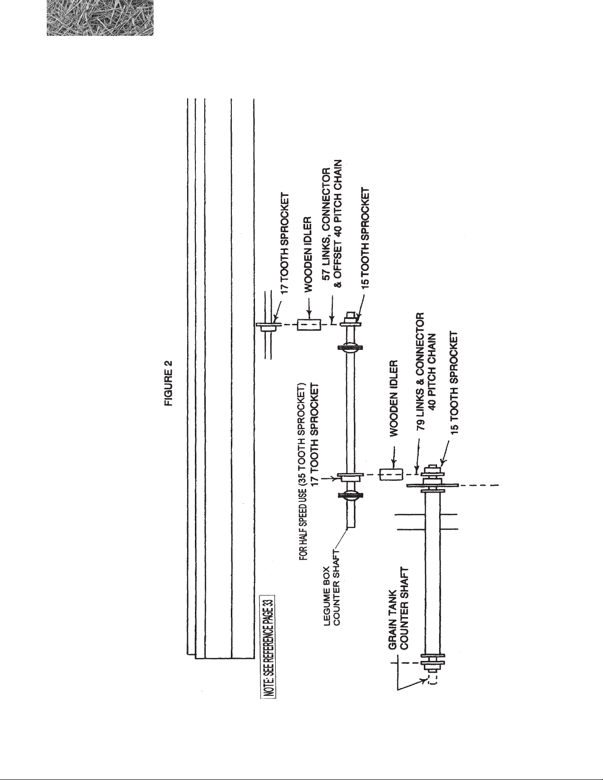
Step 3: Loosen chains, sprockets and bearings and move countershaft on grain tank. Reinstall existing
bearings, sprockets and chains and install 15 tooth sprocket as shown in Figure 2.
Step 4: Bolt legume box to grain tank using the four 3/8” x 1” bolts provided. The mounts welded to the
rear of the legume box should go between the mounting brackets installed in Step 1. Tighten all
mounting bolts securely.
Step 5: Bolt the two bearing standards to the brackets on the legume box using six 5/16 x 3/4” carriage
bolts, at washers, lock washers and nuts. Align the bearing standards before tightening bolts.
Loosely bolt the bearings to the outside of the bearing standards using the four 5/16”’ x 3/4” carriage
bolts. Install the 29” shaft with the 17 tooth sprocket BETWEEN the bearings as shown in Figure
2. Install two wooden block chain tightener using 3/8” x 2-1/2” bolts, two at washers, lock washer
and nuts. Tighten the drive chains.
Step 6: Cut 5/8” I.D. clear plastic hose to 22” lengths. Eighteen are required. Install hoses on the grain
cups rst and then on legume box cups. Dipping the ends in a liquid soap solution (one part soap to
one part water) will ease installation of the hoses.
14
77C /107C DRILLS OPERATING INSTRUCTIONS
Legume Box (Option) Installation
77C /107C DRILLS OPERATING INSTRUCTIONS
15

2.3 Legume Hopper Shipping Kit (Optional)
ITEM PART NO. QTY. DESCRIPTION
1 8700001 1 BRKT\LEGUME\LH\LEG-BOX
2 8700002 1 BRKT\LEGUME\RH\LEG-BOX
3 8700003 4 STRAP\LEGUMEBOX
4 8700008 1 BRG\BOX\LEGUME\RH
5 8700009 1 BRG\BOX\LEGUME\LH
6 2000002 2 BRG\1” W/LOCK\COLLAR
7 2000703 4 FLGETT\1\2BOLT\PLTD
8 2000016 2 BLK\WD\IDLER
9 8700011 1 SHFT\1X29\LEGUMEBOX
10 1000111 1 SPKT\B\40\17\1\1/4KW\SOFT
11 1000112 2 SPKT\B\40\15\1\1/4KW
12 6200010 3 KEY\SQ\1/4X1
13 1100232 1 CHAIN\40NP\53
14 1100246 1 CHAIN\40NP\79
15 1100224 2 CHAIN\40NP\CL
16 1100225 2 CHAIN\40NP\OL
17 3700129 18 HOSE\PVC\5/8IDX22-1/2\CLR
18 4800098 4 BOLT\HEX\3/8X1-1/4\NC
19 4800156 4 BOLT\HEX\3/8X3
20 4800029 2 BOLT\HEX\3/8X2-1/2
21 4800003 4 BOLT\HEX\3/8X1
22 4900002 14 NUT\HEX\3/8\NC
23 5000019 14 WASH\LOCK\3/8
24 500000 1 4 WASH\FLAT\3/8
25 4800153 10 BOLT\CRG\5/16X3/4\NC
26 4900003 10 NUT\HEX\5/16\NC
27 5000022 10 WASH\LOCK\5/16
16
77C /107C DRILLS OPERATING INSTRUCTIONS

Section 3: Introduction
Every effort has been made to ensure that the information contained in this manual is correct at the date of publication;
but, due to continuous improvements, DuraTech Industries reserves the right to make changes in the contents without
notice or obligation.
This manual is shipped with each machine to familiarize the operator with the proper operating, maintenance and
lubrication instructions to insure the best possible performance and service from the machine. Study and understand
these instructions thoroughly before operating the machine. We recommend that this manual be readily available for
reference at all times. Consult your DuraTech Industries dealer if any items in this manual are not understood.
DuraTech reserves the right to make changes in engineering, design and specications, add improvements, or
discontinue manufacture at any time without notice or obligation.
3.1 Ordering Parts
When ordering parts always specify your model number, serial number, and the number of the parts you wish to order.
IMPORTANT: WHEN REPLACEMENT PARTS ARE NEEDED, USE THE LISTED PART
NUMBERS AND DESCRIPTIONS TO INSURE FAST AND ACCURATE SHIPMENT OF YOUR
ORDER. WHEN ORDERING PARTS ALWAYS SPECIFY UNIT SERIAL NUMBER.
ONLY AUTHORIZED PARTS SHOULD BE USED FOR REPAIR AND/OR REPLACEMENT.
77C /107C DRILLS OPERATING INSTRUCTIONS
17

3.2 Serial Number Decal
The serial number and the machine model number are stamped on the decal. The model number and serial number are
important when service and/or parts are required.
3.3 About your 77C/107C Grain Drill
The 77C/107C Grain Drill is designed to seed No-Till, Minimum Till, or conventionally tilled elds. Two 30 gallon
tanks are available for added ballast to penetrate the tough no-till conditions.
The two compartment hopper offers the exibility of seeding with fertilizer, seeding alone, or planting two different
seeds. The metering system for each hopper is innitely adjustable.
Field hitches are available for one or multiples of two, three, and four of the model 107C Drill only. A tow hitch is also
available for the 107C Drill to allow the towing of two or more drills in transport.
18
77C /107C DRILLS OPERATING INSTRUCTIONS

Section 4: Operating Instructions
To insure long life and economical operation, we highly recommend the operator of the 77C/107C Grain Drill be
thoroughly instructed in the maintenance and operation of the machine. There is no substitute for a sound, preventative
maintenance program and a well-trained operator.
Prior to operating the Grain Drill, we recommend the operator make a visual inspection of the unit. This can be done as
the lubrication is being carried out.
4.1 Operating Instructions
Check the following:
q Hydraulic components for leaks or damage.
WARNING: Hydraulic uid escaping under pressure can be almost invisible and can have sufcient
force to penetrate the skin. When searching for suspected leaks, use a piece of wood or cardboard
rather than your hands.
If injured, seek medical attention immediately to prevent serious infection or reaction.
q Lug nuts for tightness.
q Condition of tire rims.
q Tires for proper air pressure.
q Condition of rubber convoluted hoses.
q Adjustment of all chains.
q Installation and condition of shields.
q Installation of Slow Moving Vehicle (SMV) sign.
q Condition of decals.
WARNING: Before attempting to operate this machine, refer again to Section 1 (pages 3-11) for
important safety information.
77C /107C DRILLS OPERATING INSTRUCTIONS
19

4.2 Grain Drill Setup
The 77C/107C Grain Drill may be shipped without the hydraulic lift cylinder, since the grain drill used a standard 3”
x 8” cylinder. The retracted length must be 20-1/4”, measured from the center of the mounting holes. When multiple
grain drills are used, a cylinder will be required for each grain drill.
• Set the wheels on your tractor out as wide as possible for maximum stability.
• Hitch the grain drill to the tractor.
• Connect the hydraulic hoses to the tractor’s hydraulic system.
4.3 Pressure Spring Adjustment
To gain versatility for all types of terrain and soil conditions, it is important to have a considerable amount of up and
down travel built into each individual run. When seeding on level terrain, adjust hydraulic cylinder stroke to lower
Movable Frame so openers penetrate soil approximately two (2) inches and Parallel Bars are about level when viewed
from the side. The toolbar height will be about 20” when discs are new. This will allow runs to move up or down
according to terrain.
If parallel bars are not level, it will be necessary to adjust pressure spring, or press wheel adjustment.
Proper tension of the pressure spring varies with conditions. No-till seeding may require more down pressure; loose
soil requires less. Since the pressure springs work together with the opener depth adjustment controlled by the
hydraulic cylinder, make sure that the opener depth adjustment is set correctly.
pressure spring adjustment
20
77C /107C DRILLS OPERATING INSTRUCTIONS

In extremely loose soils such as freshly worked summer fallow, it will be necessary to lessen tension on pressure spring
instead of lessening hydraulic cylinder stroke.
To adjust the pressure springs:
1. Make sure the movable frame is raised completely
up and the safety stop bar is secured.
2. Using the adjustment nut on each pressure spring,
adjust the spring to the desired length. See table
at right showing the opener pressure obtained at
various spring lengths. Under no circumstances
should the spring be adjusted to less than 10 inches.
This may damage the spring and related parts and
SPRING
LENGTH
12¼ IN.
11½ IN.
11 IN.
10½ IN.
10 IN.
OPENER
PRESSURE
135 LBS.
180 LBS.
205 LBS.
235 LBS.
300 LBS.
will also void the warranty on these parts.
4.4 Press Wheel Adjustment
In addition to rming the soil around the seed, the press wheels serve as gauge wheels for the openers. The relationship
of each press wheel and opener will remain consistent regardless of terrain or soil density. If the seed is too deep, lower
the press wheel. If the seed is too shallow, raise the press wheel.
To adjust the press wheel height:
1. Remove quick attachment pin.
2. To lower the press wheel, relocate shim washers from top to bottom. To raise the press wheel, relocate
shim washers from bottom to top.
3. Install quick attachment.
depth adjustment washer for
serial numbers 401 and up
77C /107C DRILLS OPERATING INSTRUCTIONS
21

4.5 Haybuster 77C/107C Drill Opener
The 77C/107C Drill uses a coulter-disk offset opener. The coulter blade leads the disk by 1-1/2”. Both blades are the
same size and due to the offset, there is some sliding action where the blades contact. This sliding or scissor action
provides excellent residue cutting action at ground level, especially in wet residue. The scissor action causes some
wear into the coulter blade at the point of contact. This wear is normal and the heavier coulter blade is bolted to the
bearing cage to allow easy replacement.
depth adjustment washer for
serial numbers 401 and up
One complete turn changes points A and B (DWG. 1) the amount shown in DWG. 2. It takes 6 turns to bring points A
and B back together.
4.5A Control Plates
Control plates are mounted using a spring, bolt, guide tube, washers and nut assemblies. The two outer and center
assemblies use a larger washer, guide tube, washer, bolt and top locknut. When installing these assemblies, tighten
the bolt until the guide tube is tight against the tank. The remaining assemblies use a spring, washers, bolt and a top
locknut. On these remaining assemblies, the springs should be tightened to 1-1/16” - 1-1/8”.
remaining bolt assemblies
outer bolt assemby
control plate
22
77C /107C DRILLS OPERATING INSTRUCTIONS

control plate
remaining bolt assemblies
center bolt assembly
4.6 Feed Wheel Space Adjustment
Large seeds require more space between feed wheel lugs and tank wall than small seeds to prevent cracking. Small
seeds require less space to provide an even ow. Therefore each seed listed in the feed rate chart, pages 28 to 31, shows
a required wheel space.
feed wheel space
adjustment.
FEED WHEEL SPACE ADJUSTMENT
bolt B
bolt A
1. Remove the feed wheel covers.
2. Loosen the eight bolts A and B. There are four sets
of bolts for each feed wheel - two on the outer end
of the hopper and six inside the hopper.
3. Select the proper space gauge using the wheel
space chart.
4. Install the proper space gauge as shown.
5. Slide the feed wheel toward the gauge until the
feed wheel lugs, gauge and hopper are pressed
together. Tighten the eight bolts.
6. Recheck the feed wheel space adjustment.
7. Install the feed wheel covers.
one set of feed wheel space
adjustment bolts
The feed wheel space adjustment provides the proper clearance for the type of seed or fertilizer
being used.
77C /107C DRILLS OPERATING INSTRUCTIONS
23

4.7 Drill Cleanout Slides
Cleanout slides are provided on both grain and fertilizer
tanks. Handles for opening and closing the slides are
located on the left side of the drill.
drill cleanout slides
handles
24
77C /107C DRILLS OPERATING INSTRUCTIONS
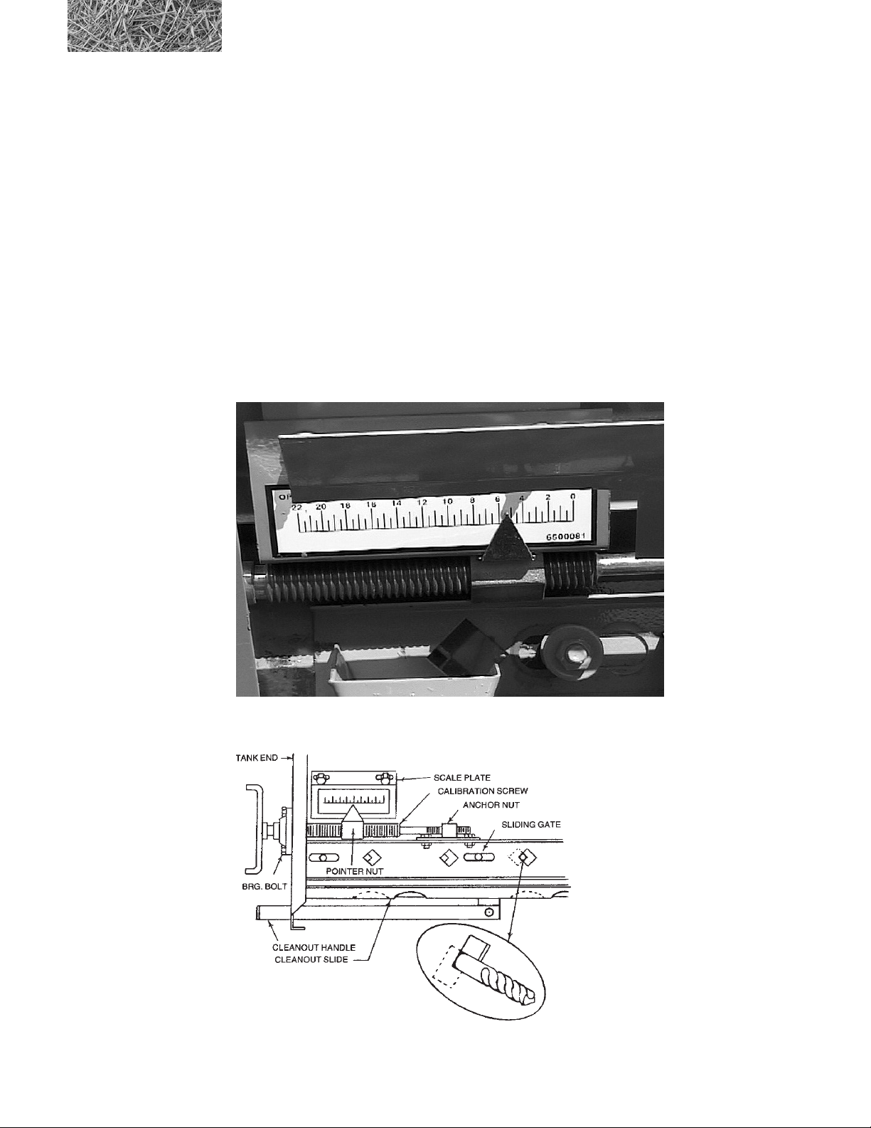
4.8 Calibration Pointer Adjustment
Grain and fertilizer sliding gates are preadjusted at the factory. In the event any part of the calibrating mechanism is
removed or replaced, it can be recalibrated in this order:
1. Place both pointer nut and anchor nut in the center of their respective thread.
2. Insert a short length of 7/16” rod or the shank end of a 7/16” drill bit into the square hole in sliding gate
as shown.(gure 4.1)
3. Tighten bearing bolts securing calibration screw to end of tank.
4. Tighten bolts securing anchor nut to sliding gate.
5. Place scale plate on tank so number 8 is directly in line with top of pointer. This will insure pointer
setting to coincide with chart. Scale plate must be parallel with calibration screw to allow pointer to
operate smoothly along plate.
calibration pointer
adjustment
gure 4.1
77C /107C DRILLS OPERATING INSTRUCTIONS
25

4.9 SETTING AND CHECKING FEED RATE
front feed wheel alignment
For most seeding, the front feed wheel should be aligned as shown above. Set the pointer on number 8. The center of
the front feed wheel should be centered in the opening as viewed from outside of the box.
Rear feed wheel alignment
Setting the rear feed wheel, set pointer on number 22. The right edge of the rear feed wheel should line up with the right
point of the diamond as viewed from outside of the box.
The rates shown on the charts serve only as a starting point. Due to variations in material size and density the rates may
vary from the chart. The following methods may be used to determine the proper setting for your particular seed or
fertilizer.
Setting and checking feed rate using wheat as an example.
1. You want to seed wheat at a rate of 95 lbs. per acre on 7” spacing.
2. Seed rate charts calls for a wheel space of 1/8” (page 28). Pointer set on 8 (see illustration above). The
adjustment should be made before lling grain tank.
3. Make sure feed wheel cover is in place. Put grain in tank.
4. Seed far enough so you can visually check grain owing into seed cups.
26
77C /107C DRILLS OPERATING INSTRUCTIONS

The addition of the single agitator to the standard drill box will prevent these seeds from bridging above the feed
wheels. The single agitator may be added to all 77C/107C drills.
Alti wildrye
Bromegrass #
Intermediate wheatgrass
Killdeer sideoats #
Pubescent wheatgrass
Streambank wheatgrass
Tall wheatgrass
Western wheatgrass
# Extremely trashy samples may require the double agitator.
4.10 CHECKING FEED RATE
1. Measure a distance of 415’ on a drill with 7” spacing and mark. Remove one hose from seed hopper
on each drill. Attach a container (cloth or plastic bag) to hopper to collect seed.
2. Operate drill at intended planting speed through entire length of test track.
3. Weigh the sample in ounces (less weight of sample container). Use the following formula to determine
lbs./acre for your particular shank spacing.
7” Spacing - oz. x 11.25 = lbs./acre
EXAMPLE
Sample and container weighs 9.9 ounces
Container weighs - 1.5 ounces
Weight of sample only 8.4 ounces
4. Use formula No. 1 to gure pounds per acre. 8.4 ounces x 11.25 = 94.5 pounds per acre.
5. To calibrate a seed not shown on the chart or a mix of different seeds, compare to a similar charted
seed to obtain a trial setting. Recalibrate as necessary.
6. The same method may be used to determine fertilizer rates.
77C /107C DRILLS OPERATING INSTRUCTIONS
27

POINTER SETTING
CHART FOR DRILLING GRAIN IN POUNDS PER ACRE
100 DRILL DETERMINING SEED POPULATION
28
Series 100
Spacing 7”
Model No. 77C/107C
The 107C Drill seeds 10.50’ / 126” per pass; the 77C Drill seeds 7’/ 84” per pass.
The 107C Drill travels 4149 feet to seed 1 acre; the 77C Drill travels 6223’ to seed 1 acre.
Following is the lineal feet of seeded row to seed 1 acre.
7” rows - 74,700 ft/acre
EXAMPLE:
150,000 bean plants desired per acre on 7” row spacing
** = indicates wheel spacing
77C /107C DRILLS OPERATING INSTRUCTIONS
150,000 divided by 74,700 = 2.0 beans per ft.
10 ft. of row - 20 beans.
POINTER SETTING
POINTER SETTING
CHART FOR DRILLING GRAIN IN POUNDS PER ACRE
Spacing 7 Inch
77C /107C DRILLS OPERATING INSTRUCTIONS
** = indicates wheel spacing
CHART FOR DRILLING GRAIN IN POUNDS PER ACRE
Spacing 7 Inch
** = indicates wheel spacing
29

POINTER SETTING
CHART FOR DRILLING GRAIN IN POUNDS PER ACRE
30
Spacing 7 Inch
** = indicates wheel spacing
77C /107C DRILLS OPERATING INSTRUCTIONS

IN POUNDS PER ACRE
LEGUME BOX ATTACHMENT FOR 77C/107C DRILL ON 7” SPACING
SEED MIXTURES
SELECT THE SETTING FOR THE DESIRED
QUANTITY OF EACH SEED.
ADD INDIVIDUAL SETTINGS.
EXAMPLE:
LBS/ACRE NOTCH
ALFALFA 5 2
SWEET CLOVER 5 2
TIMOTHY 2 1
TOTAL 5
WHEN USING HALF SPEED DRIVE DIVIDE
CHARTED RATES BY TWO. REPLACE 17
TOOTH SPROCKET ON COUNTERSHAFT
WITH 35 TOOTH. (SEE MANUAL FOR
DETAILS.)
DENSITY OF THE SAMPLES USED TO
PREPARE THIS CHART ARE GIVEN IN THE
FIRST COLUMN TO THE RIGHT OF THE
CROP NAME IN POUNDS PER BUSHEL.
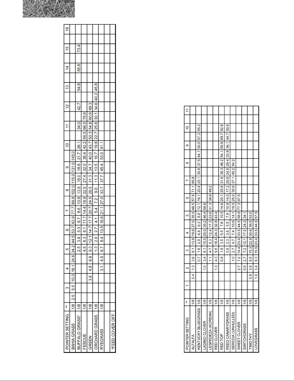
CHART FOR DRILLING LEGUMES AND SMALL GRASSES
77C /107C DRILLS OPERATING INSTRUCTIONS
31

CHART FOR DRILLING GRASS IN POUNDS PER ACRE
To obtain the desired seeding rate of the chaffy native
grasses it may be necessary to adjust the feed shaft speed.
The charts on page 32 list the sprocket combinations and
relative speed in revolutions per acre. Use these charts as
a guideline in choosing the correct sprocket combinations.
On a standard drill box, sprocket A has 14 teeth and
sprocket B has 18 teeth. There are 12 tooth and 24 tooth
sprocket included in the shipping kit for the native grass
attachment.
Also see information in section 5.4
32
Spacing 7 Inch
** = FOR BEST RESULTS OBTAIN THE MOST TRASH-FREE SEED AVAILABLE.
77C /107C DRILLS OPERATING INSTRUCTIONS

4.11 Drilling with the Grain Drill
If the grain drill was transported using the optional end hitch, the rear wheels will need to be rotated as follows:
1. Use the hydraulic system to lower the openers onto solid soil or use a jack to raise the drill frame and
remove the weight from the rear wheels.
2. Remove the bolts from each wheel.
rotating the wheels for
drilling (wheel shown in
drilling position)
3. Rotate the wheels 90° and insert bolts.
4. Using a tape measure, align the wheels so that they are parallel with each other and the frame as shown.
Adjust and secure the stop bolt #2.
77C /107C DRILLS OPERATING INSTRUCTIONS
NOTE: Step 4 covers alignment of the wheels. Once this adjustment is set, it should not
normally be necessary to readjust it. Alignment of the wheels in the working position is less
critical than in the transport position because of the softer surfaces and slower speeds.
33

5. Tighten the bolts.
6. Remove the jack, if used.
7. After the tractor is hitched to the front hitch, move the drill ahead slowly until the front swivel wheels are
properly positioned.
At this point the grain drill should be properly set up and adjusted according to the instructions in the preceding
sections.
Load the tanks with seed and/or fertilizer. Rotate the drive wheel by hand to make sure that the feed wheel shafts are
free to turn. This is particularly important if the drill was transported with fertilizer and seed in the hoppers.
Start the tractor, retract the cylinder completely, and begin drilling.
Periodically check for proper seed depth and feed rate.
When the seeding operation is nished, park the drill over a sheet of plastic, canvas, etc. Pull one of the cleanout side
control levers out to empty the remaining seed or fertilizer. Collect the seed or fertilizer. Repeat the procedure for the
other hopper.
34
77C /107C DRILLS OPERATING INSTRUCTIONS

4.12 SUGGESTIONS
When preparing to sow damp fertilizer that has been sitting in the tank for several hours, stir the fertilizer all the way to
the bottom to break up any blocks of fertilizer which have become cemented together.
The amount of fertilizer sown will vary with the moisture content and quality of the fertilizer.
4.13 REAR WHEEL SWIVEL AND ADJUSTMENT
Both rear wheels are designed to swivel 90° for the purpose of transporting drills endways. Adjusting bolts are
provided for aligning wheels in transport position as well as in forward position. Transport position is most critical for
tire wear due to hard surface roads and faster speeds.
CAUTION: Transporting drills with seed and fertilizer in the tanks is not recommended. If drills
are moved any distance with seed or fertilizer in tanks, either in transport or eld position, materials
will settle around feed wheels. Before starting to seed, operator should check with a wrench on drive
end of feed wheel shaft to make sure they are free to turn. Shaft may be turned either clockwise or
counterclockwise with openers in raised position.
WARNING: Maximum transport speed should never exceed 20 M.P.H., and should be less where
conditions demand.
4.14 TRANSPORTING THE GRAIN DRILL
The rear wheels swivel 90° to transport the drill end ways with the optional end hitch. These wheels must be carefully
aligned before transporting the drill because of the hard surfaces.
To rotate the rear wheels:
1. Use the hydraulic system to lower the openers onto solid soil or use a jack to raise the drill frame and
remove the weight from the rear wheels.
2. Remove the lock bolts from each wheel.
3. Rotate the wheels 90° and insert the lock bolts.
NOTE: Step 4 covers alignment of the wheels. Once this adjustment is set, it should not normally be
necessary to readjust it.
77C /107C DRILLS OPERATING INSTRUCTIONS
35

rotating the wheels for
drilling (wheel shown in
drilling position)
4. Using a string, align the wheels as shown. Adjust and secure the stop bolts.
5. Tighten the lock bolts.
6. Raise the openers or
remove the jack. Secure
the torque bar in the
transport position with
the safety stop bar.
rear wheel alignment - transport position
7. After the tractor is hitched to the end hitch, move the drill ahead slowly until
the front swivel wheels are properly positioned.
36
step # 4
stop bolt
77C /107C DRILLS OPERATING INSTRUCTIONS

4.15 CLEANING GRAIN TANKS AND LEGUME BOXES
CLEAN grain tanks and/or legume boxes on the 77C/107C Drill after using inoculated, treated or
coated seeds. Failure to clean tanks will cause damage to moving parts. This damage is NOT covered
by warranty. Always add graphite to treated seeds.
4.16 PREPARING FOR STORAGE
To prepare the 77C/107C Drill for storage, perform the following steps:
1. Install safety stop bar to keep planting units off the ground and to minimize rusting. Before drill is stored,
clean out slides should be opened to remove as much seed and fertilizer as possible. Both tanks should
be ushed out thoroughly to prevent any caking of seed or fertilizer. Open and close slides while ushing
to allow any fertilizer that might be under the calibration slide to work its way free. Fertilizer can be
damaging if left in contact with metal parts for a prolonged period.
2. Clean all mud, dirt, grease and other foreign material from the exterior of the machine. Wash the complete
machine. Repaint places where bare metal is exposed - this will inhibit rusting.
3. After inside of the tank is thoroughly dry, apply a coat of oil or diesel fuel to calibration slide, bearings
and other parts that have been in contact with fertilizer or seed.
4. Remove the chains and wash them in solvent. Using a clean cloth, wipe off the chains. Soak the chains
in engine oil. Drain off the excess oil and install the chains on the grain drill.
5. Coat all chains and exposed hydraulic cylinder rod with a Valvoline Tectyl 506 oil or equivalent.
6. Lubricate machine thoroughly according to the lubrication instructions.
7. Drain water from ballast tanks, if installed.
8. If possible, store the machine in a dry, protected place. If it is necessary to store the machine outside,
cover it with plastic, waterproof canvas, or other suitable protective material.
9. Check the machine for any worn or broken parts. By ordering parts now, you will avoid delays when it
is time to remove the machine from storage. When ordering parts always specify machine serial number
and the part number of the replacement part. Part numbers can be found in the Parts List Manual.
4.17 REMOVING FROM STORAGE
To remove the 77C/107C Drill from storage, perform the following steps:
1. Remove all protective coverings.
2. Remove all excess oil from chains and cylinder rods. Lubricate machine in accordance with lubrication
instructions found in this manual.
3. Check all hydraulic hoses for deterioration and, if necessary, replace. Tighten any loose bolts, nuts and
hydraulic ttings.
4. Follow prestarting inspection.
77C /107C DRILLS OPERATING INSTRUCTIONS
37

A Tradition of Innovation Since 1966
38
77C /107C DRILLS OPERATING INSTRUCTIONS

Section 5: Grass Seeding Reference
All Haybuster 77C/107C Grain Drills are very versatile. These base drills are capable of accurately metering most
common seeds and fertilizer. The seed will be placed at the correct depth in conventional and minimum tillage and
most zero-tillage situations. Through the use of special attachments, Haybuster 77C/107C Grain Drills can be used for
seeding of various types of grass seeds including small-seed legumes and chaffy native grasses. When grass seeding is
complete, each of these drills are capable of seeding and fertilizing your conventional crops. For more information on
operating the drill, settings and procedures, please see Section 4: Operating Instructions.
5.1 Grass Seeding Attachments
The following attachments are available for grass seeding:
• Legume box
• Single agitator
• Double agitator
• 2” I.D. seed tubes
• Depth bands
Many grasses can be metered through the standard seed box with no additional equipment. However, some of the
grasses listed below can be metered more accurately by using some of the special attachments listed on the following
pages.
*Alfalfa *Alsike clover @Altiwild rye *Bahiagrass
*Birdsfoot trefoil @Bromegrass Buffalograss Fescue
Green needlegrass @Intermediate wheatgrass *Kentucky bluegrass @Killdeer sideoats
*Ladino clover *Lespedeza (unhulled) *Lovegrass Orchard grass
@Pubescent wheatgrass Ryegrass *Red clover *Red top
*Reed cararygrass *Serecia (unhulled) *Sweet clover *Switchgrass
@Streambank wheatgrass *Timothy @Tall wheatgrass @Western wheatgrass
* See legume box section, page 40
@ See single agitator section, page 40
77C /107C DRILLS OPERATING INSTRUCTIONS
39

5.2 Legume Box Applications
The legume box attachment is designed to accurately meter the small seeds listed below.
Alfalfa Alsike clover Bahia grass Birdsfoot trefoil
Fescue Kentucky bluegrass Ladino clover Lesoedeza (Korean)
Lovegrass Orchard grass Red clover Red top
Reed canarygrass Rye grass Serecia (unhulled) Sweet clover
Switchgrass Tibbet clover Timothy Vetch
For more information please see the Chart for drilling legumes and small grasses on page 31.
5.3 Single Agitator Applications
The addition of the single agitator to the standard drill box will prevent these seeds from bridging above the feed
wheels.
Alti wildrye Bromegrass # Intermediate wheatgrass
Killdeer sideosts # Pubescent wheatgrass Streambank wheatgrass
Tall wheatgrass Western wheatgrass
# Extremely trashy samples may require the double agitator.
For more information please see the Chart for drilling grain on page 30.
5.4 Special Instructions for Warm Season Grasses
Warm season grasses tend to be very low bulk and are very trashy or chaffy in appearance. Special equipment required
to properly meter these grasses is listed below.
• Double agitator (top and bottom)
• Larger opening in drill box (1-1/2 inch)
• 2 inch I.D. grass tube kit
• Sprocket set (feed shaft speed adjustment)
Obtain the best quality seed available for best results. Trashier samples may need to be blended with heavier seed to
improve metering capabilities. Center the feed wheels as shown on page 23. Be sure to check the feed wheels as shown
on page 23.
Blue grammagrass Big bluestem Indian grass Little bluestem Prairie sandreed
40
77C /107C DRILLS OPERATING INSTRUCTIONS

To obtain the desired seeding rate of the chaffy native
grasses it may be necessary to adjust the feed shaft speed.
The charts on page 32 list the sprocket combinations and
relative speed in revolutions per acre. Use these charts as
a guideline in choosing the correct sprocket combinations.
On a standard drill box, sprocket A has 14 teeth and
sprocket B has 18 teeth. There are 12 tooth and 24 tooth
sprocket included in the shipping kit for the native grass
attachment.
5.5 Pure Live Seed Calculations
Any sample of bulk seed always has a certain percentage of non-viable seed and inert matter. In cereal grains, this
percentage is quite small and can usually be ignored when determining seeding rates. Grass seeds can have a very
high percentage of dormant and non-viable seed, and inert matter. These high percentages must be considered when
determining grass seeding rates.
For example: You wish to plant Big Bluestem (Chart pg 32) at a rate of 12 ponds of pure live seed (pls) per acre.
A typical grass seed tag might appear as follows:
Big Bluestem
Weed seed……………..0.10% Lot No………….83101
Noxious weed seed…….0.00% Germ……………52.0%
Other crops…………….0.05% Date of test………3-86
Inert matter……………40.05% Grown…………Kansas
Step 1. Determine the total percentage of inert matter from the seed tag
Weed seed 0.10%
Noxious weed seed 0.00%
Other crops 0.05%
Inert matter 40.05%
40.20%
Step 2. Subtract the percentage of inert matter from 100% to nd pure seed percentage.
100.0% - 40.20% = 59.80%
Step 3. Divide the pounds of pure live seed desired by the percent pure seed.
12 lbs pls/0.5980= 20.07 lbs pure seed
77C /107C DRILLS OPERATING INSTRUCTIONS
41

Step 4. Divide pounds of pure seed by the germination percentage to get bulk seed.
20.07/0.52 = 38.6 lbs of bulk seed
So 38.6 lbs of bulk seed per acre must be sown to get 12 lbs of pure live seed per acre.
For most seeding, the feed wheel should be aligned as shown above. Set the pointer on number 8. The center of the
feed wheel should be centered in the opening as viewed from outside of the box.
When seeding the grasses listed on page 32, move the feed wheel as shown above. Set the pointer on number 22,
the center of the feed wheel should be centered in the opening as viewed form outside of the box. Generally, a small
screwdriver or similar tool may be inserted through the opening into the tank and used to push the wheel into position.
The agitator blades inside the drill box may need to be re-centered over the feed wheels to prevent interference.
42
77C /107C DRILLS OPERATING INSTRUCTIONS

Section 6: Lubrication
All 77C/107C Grain Drills are completely serviced at the factory before shipping. However, the operator should make
a check of all grease ttings on the unit before beginning to operate it so as to become familiar with their location and
the correct service schedule.
Use only a high quality, multi-purpose grease when lubricating the unit. Make sure all ttings and the nozzle of the
grease applicator are clean before applying the grease. If any grease ttings are missing, replace them immediately.
Lubricating of all pillow block and ange-type self-aligning ball or roller bearings should be done slowly to help
prevent bearing seal damage. Use caution when using a high pressure, high volume gun.
Description Type Frequency No. Zerks
1. Swivel Wheel Pivot Grease 20 Hrs. 2
2. Torque Tube Bushings Grease 40 Hrs. 2
3. Universal Joints Grease 40 Hrs. 2
4. Square Drive Line Grease 40 Hrs. 2
5. Feed Wheel Shaft Grease 100 Hrs. 6
6. Roller Chains Oil Daily In Dusty Conditions
7. Tool Bar Bushing Grease 20 Hrs. 2
8. Lift Arm Bushing Grease 20 Hrs. 2
9. Lift Arm Grease 20 Hrs. 2
10. Drive Wheel Frame Grease 20 Hrs. 2
11. Packer Wheel Bearings and Coulter-Disk Bearings are Non-Relubable.
12. Cylinder Clevis Pin Grease 20 Hrs. 1
swivel wheel pivot
lubrication zerk
77C /107C DRILLS OPERATING INSTRUCTIONS
43

torque tube bushings
lubrication points
universal joints and
square drive line
lubrication zerks
feed wheel shaft
lubrication zerk
44
77C /107C DRILLS OPERATING INSTRUCTIONS

tool bar bushing
lubrication zerk
lift arm bushing
lubrication zerk
drive wheel frame
lubrication zerk
roller chains lubrication
77C /107C DRILLS OPERATING INSTRUCTIONS
45

APPENDIX A: WARRANTY
Duratech Industries International, warrants to the original purchaser for one year from purchase date that this product
will be free from defects in material and workmanship when used as intended and under normal maintenance and
operating conditions. This warranty is limited to the replacement of any defective part or parts returned to our factory
in Jamestown, N.D., within thirty (30) days of failure.
This warranty shall become void if in Duratech Industries International’s judgment the machine has been subject to
misuse, negligence, alterations, damaged by accident or lack of required normal maintenance, or if the product has been
used for a purpose for which is was not designed.
All claims for warranty must be made through the dealer which originally sold the product and all warranty adjustments
must be made through same.
This warranty does not apply to tires or bearings or any other trade accessories not manufactured by Duratech
Industries International. Buyer must rely solely on the existing warranty, if any, of these respective manufacturers.
Duratech Industries International shall not be held liable for damages of any kind, direct, contingent, or consequential
to property under this warranty. Duratech Industries International cannot be held liable for any damages resulting from
causes beyond its control. Duratech Industries International shall not be held liable under this warranty for rental costs
or any expense or loss for labor or supplies.
Duratech Industries International reserves the right to make changes in materials and/or designs of this product at any
time without notice.
This warranty is void if Duratech Industries International does not receive a valid warranty registration card at its ofce
in Jamestown, N.D., within 10 days from date of original purchase.
All other warranties made with respect to this product, either expressed or implied, are hereby disclaimed by Duratech
Industries International.
46
77C /107C DRILLS OPERATING INSTRUCTIONS

APPENDIX B: SPECIFICATIONS
77C Drill 107C Drill
Overall Width: 91” 125”
Seeding Width: 84” 126”
End Transport Width: 155”
Height: 73” 73”
Weight: 3,600 lbs 4,200 lbs
Tire Size- Front: 9.5x14 Implement 9.5x14 Implement
Tire Pressure 44 PSI 44 PSI
Tire Size- Rear: 7.6x15 implement 7.6x15 implement
Tire Pressure 32 PSI 32 PSI
Tire Size- Drive: 20X8-10 4-Ply 20X8-10 4-Ply
Tire Pressure 28 PSI 28 PSI
Hopper Capacity:
Grain- Front: 10 Bu. 14 Bu.
Granulated Fertilizer: 10 Bu. 14 Bu.
Grain- Front & Rear: 20 Bu. 28 Bu.
Legume Box: 1.5 Bu. 2 Bu.
Feed System: innitelyadjustablemeter innitelyadjustablemeter
Hoses: rubber convoluted rubber convoluted
Row Spacing: 7” 7”
Openers - Double Disc: 14” 14”
Press Wheels - Standard: 2” x 15-1/2” 2” x 15-1/2”
Press Wheels - Optional: 2” x 13” 2” x 13”
Options:
Swivel Hitch 1-2-3-4 Drill Hitch and Components
Acre Counter Swivel Hitch
Legume Box Acre Counter
Native Grass Kit Hitch Winch
Ballast Tanks Ballast Tanks
Gauge Wheels End Hitch
Stabilizer - Front and Rear
Legume Box
Native Grass Kit
Gauge Wheels
False Bottom
77C /107C DRILLS OPERATING INSTRUCTIONS
47

A Tradition of Innovation Since 1966
48
77C /107C DRILLS OPERATING INSTRUCTIONS

77C/107C DRILLS
107C DRILL - S.N. 101100017C & UP
77C DRILL - S.N. 77110001C & UP
Part 2:
Parts Reference
49

77C MAIN FRAME ASSEMBLY (FOR S.N. THRU 0075)
50
77C/107C DRILLS PARTS REFERENCE

77C MAIN FRAME ASSEMBLY (FOR S.N. THRU 0075)
ITEM PART QTY. PART DESCRIPTION
1 2600008 2 TIRE\7:60X15\8PLY;IMP
2 2600013 1 TIRE\9.5LX14\8PLY
3 2600601 1 WHL\6-BOLT\14X8
4 2600606 2 WHL\5-BOLT\15X5
5 2600825 1 WHL\IMP\9.5X14\TIRE&RIM (includes 2600013 and 2600601)
6 2600834 2 WHL\IMP\7.60X15\TIRE&RIM (includes 2600008 and 2600606)
7 2900004 2 CUP\INNER\WHEEL HUB
8 2900011 2 HUB\COMPLETE (includes 2900004, 2900013, 2900014, 2900015, 2900016, 2900018)
9 2900013 2 CAP\DUST\WHL;HUB(DC-13)
10 2900014 2 SEAL\GREASE(517) (15190)
11 2900015 2 CONE\INNER/WHL HUB(48548)
12 2900016 2 CUP\INNER\WHL:HUB(48510
13 2900018 2 CONE\OUTER\WHL;HUB(67048
14 2900084 2 SPACER\HUB\WHEEL
15 2900085 2 SEAL\WHL;HUB(20078)
16 2900086 2 CONE\2788\WHL;HUB
17 2900087 2 CUP\BRG\HUB\WHL\2720
18 2900089 1 HUB\H-628(FORK)\COMPLETE
19 3000018 1 SPNDL\FORK
20 3800041 4 FTG\LUB\1/8MPXZERK\ADAPT
21 3800082 5 FTG\LUB\1/4NFXZERK\ADAPT
22 3800111 1 FTG\1/8MPX1/8FP\90\ST;EL
23 3800126 1 FTG\LUB\1/8MPXZRK\2-5/8
24 4800017 1 BOLT\HEX\3/4X3
25 4800018 4 BOLT\HEX\1/2X1-1/4
26 4800068 4 BOLT\HEX\1/2X3
27 4800082 60 BOLT\HEX\1/2X1-1/2
28 4800100 4 BOLT\HEX\5/8X4
29 4800115 3 BOLT\HEX\3/4X2-1/2
30 4800120 1 PIN\COT\3/16X1-3/4
31 4800141 4 BOLT\HEX\1/2X4-1/2
32 4800157 4 PIN\COT\3/16X2
33 4800158 2 BOLT\HEX\5/8X4-1/2
34 4800626 2 BOLT\HEX\1X11\NC
35 4900001 66 NUT\HEX\1/2\NC
36 4900004 4 NUT\HEX\3/4\NC
37 4900005 5 NUT\HEX\5/8\NC
38 4900012 4 NUT\TPLCK\5/8\NC
39 4900014 6 NUT\TPLCK\1/2\NC
40 4900015 2 NUT\NYLCK\1\NC
41 4900115 2 NUT\CASTLE\1\1”-14
42 4900054 2 NUT\CASTLE\1/2\NF
43 4900094 10 NUT\TAPER\WHEEL\1/2\NF\
44 4900127 2 NUT\TPLCK\1\NC
45 5000002 4 WASH\FLAT\5/8
46 5000003 3 WASH\LOCK\5/8
47 5000004 16 WASH\FLAT\1/2
48 5000006 64 WASH\LOCK\1/2
49 5000012 4 WASH\LOCK\3/4
50 5000032 1 WASH\MACH\2IDX10GA
51 5000040 2 WASH\BUSH;MACH\1
52 5000055 2 WASH\SPINDLE\7/8
53 5000075 1 WASH\MACH\3X2-1/16X1/4
54 6100044 1 SPRNG\2-1/16X3/8WIRE2”LG
55 7500134 4 GROM 1.25ODX 17/32IDX1.25
56 7500858 1 GRMT\RBBR\2-1/4X2IDX1/4T
57 8400032 1 GOOSENECK
58 8400036 2 TUBE\TORQUE\PIVOT
59 8400038 2 ARM\LIFT
60 8400039 2 BUSH\ARM\LIFT\1X5/8X2-1/8
61 8400041 2 SPNDL\REAR\WHL
62 8400042 2 BOLT\PIVOT\REAR\WHL
63 8400130 1 STEP\REAR\RH
64 8400131 1 STEP\REAR\LH
65 8400132 2 STRAP\REAR\STEP;MOUNT
66 8400150 2 BUSH\TOOL_BAR\1-1/4X3/4X2
67 8400272 1 TUBE\TORQUE
68 8400281 1 CAP\RECESSED\WHL\SWIVEL
69 8400282 1 ROD\THRDD\5/8X4
70 8400283 1 FORK\WHL\SWVL
71 8400701 1 BAR\TOOL\7”SPCNG
72 8400702 1 WALKWAY\100_SERIES
73 8400742 1 FRM\MAIN\77
74 8400785 1 BRKT\HOSE\MINDER
75 8400799 1 PIN\CLEVIS\1X3\GREASE
76 8800021 2 RETAINER\SPNDL
77C/107C DRILLS PARTS REFERENCE
51

77C MAIN FRAME ASSEMBLY (FOR S.N. 0076 AND UP)
52
77C/107C DRILLS PARTS REFERENCE

77C MAIN FRAME ASSEMBLY (FOR S.N. 0076 AND UP)
ITEM PART QTY. PART DESCRIPTION
1 2600008 2 TIRE\7:60X15\8PLY;IMP
2 2600013 1 TIRE\9.5LX14\8PLY
3 2600601 1 WHL\6-BOLT\14X8
4 2600606 2 WHL\5-BOLT\15X5
5 2600825 1 WHL\IMP\9.5X14\TIRE&RIM (includes 2600013 and 2600601)
6 2600834 2 WHL\IMP\7.60X15\TIRE&RIM (includes 2600008 and 2600606)
7 2900004 2 CUP\INNER\WHEEL HUB
8 2900011 2 HUB\COMPLETE (includes 2900004, 2900013, 2900014, 2900015, 2900016, 2900018)
9 2900013 2 CAP\DUST\WHL;HUB(DC-13)
10 2900014 2 SEAL\GREASE(517) (15190)
11 2900015 2 CONE\INNER/WHL HUB(48548)
12 2900016 2 CUP\INNER\WHL:HUB(48510
13 2900018 2 CONE\OUTER\WHL;HUB(67048
14 2900084 2 SPACER\HUB\WHEEL
15 2900085 2 SEAL\WHL;HUB(20078)
16 2900086 2 CONE\2788\WHL;HUB
17 2900087 2 CUP\BRG\HUB\WHL\2720
18 2900089 1 HUB\H-628(FORK)\COMPLETE
19 3000018 1 SPNDL\FORK
20 3800041 4 FTG\LUB\1/8MPXZERK\ADAPT
21 3800082 5 FTG\LUB\1/4NFXZERK\ADAPT
22 3800111 1 FTG\1/8MPX1/8FP\90\ST;EL
23 3800126 1 FTG\LUB\1/8MPXZRK\2-5/8
24 4800017 1 BOLT\HEX\3/4X3
25 4800018 4 BOLT\HEX\1/2X1-1/4
26 4800068 4 BOLT\HEX\1/2X3
27 4800082 60 BOLT\HEX\1/2X1-1/2
28 4800100 4 BOLT\HEX\5/8X4
29 4800115 3 BOLT\HEX\3/4X2-1/2
30 4800141 4 BOLT\HEX\1/2X4-1/2
31 4800157 4 PIN\COT\3/16X2
32 4800158 2 BOLT\HEX\5/8X4-1/2
33 4800559 1 PIN\LYNCH\5/16X2-1/2\W/SQ;WIRE;KEEPER
34 4800626 2 BOLT\HEX\1X11\NC
35 4900001 66 NUT\HEX\1/2\NC
36 4900004 4 NUT\HEX\3/4\NC
37 4900005 5 NUT\HEX\5/8\NC
38 4900012 4 NUT\TPLCK\5/8\NC
39 4900014 6 NUT\TPLCK\1/2\NC
40 4900015 2 NUT\NYLCK\1\NC
41 4900115 2 NUT\CASTLE\1\1”-14
42 4900054 2 NUT\CASTLE\1/2\NF
43 4900094 10 NUT\TAPER\WHEEL\1/2\NF\
44 4900127 3 NUT\TPLCK\1\NC
45 5000002 4 WASH\FLAT\5/8
46 5000003 3 WASH\LOCK\5/8
47 5000004 16 WASH\FLAT\1/2
48 5000006 64 WASH\LOCK\1/2
49 5000012 4 WASH\LOCK\3/4
50 5000014 2 WASH\FLAT\1
51 5000032 1 WASH\MACH\2IDX10GA
52 5000040 2 WASH\BUSH;MACH\1
53 5000055 2 WASH\SPINDLE\7/8
54 5000075 1 WASH\MACH\3X2-1/16X1/4
55 6100044 1 SPRNG\2-1/16X3/8WIRE2”LG
56 7500134 4 GROM 1.25ODX 17/32IDX1.25
57 7500858 1 GRMT\RBBR\2-1/4X2IDX1/4T
58 8101352 1 BOLT\HEX\1X6\GREASE
59 8400032 1 GOOSENECK
60 8400036 2 TUBE\TORQUE\PIVOT
61 8400038 2 ARM\LIFT
62 8400039 2 BUSH\ARM\LIFT\1X5/8X2-1/8
63 8400041 2 SPNDL\REAR\WHL
64 8400042 2 BOLT\PIVOT\REAR\WHL
65 8400130 1 STEP\REAR\RH
66 8400131 1 STEP\REAR\LH
67 8400132 2 STRAP\REAR\STEP;MOUNT
68 8400150 2 BUSH\TOOL_BAR\1-1/4X3/4X2
69 8400281 1 CAP\RECESSED\WHL\SWIVEL
70 8400282 1 ROD\THRDD\5/8X4
71 8400283 1 FORK\WHL\SWVL
72 8400701 1 BAR\TOOL\7”SPCNG
73 8400702 1 WALKWAY\100_SERIES
74 8400785 1 BRKT\HOSE\MINDER
75 8400808 1 FRM\MAIN\77C
76 8400809 1 TUBE\TORQUE\107C\77C
77 8400901 1 STOP\CYL\PVT
78 8800021 2 RETAINER\SPNDL
77C/107C DRILLS PARTS REFERENCE
53

107C MAIN FRAME ASSEMBLY (FOR S.N. THRU 0880)
54
77C/107C DRILLS PARTS REFERENCE

107C MAIN FRAME ASSEMBLY (FOR S.N. THRU 0880)
ITEM PART QTY. PART DESCRIPTION
1 2600008 2 TIRE\7:60X15\8PLY;IMP
2 2600013 1 TIRE\9.5LX14\8PLY
3 2600601 1 WHL\6-BOLT\14X8
4 2600606 2 WHL\5-BOLT\15X5
2600825 WHL\IMP\9.5X14\TIRE&RIM (includes #2 & #3)
2600834 WHL\IMP\7.60X15\TIRE&RIM (includes #1 & #4)
5 2900004 2 CUP\INNER\WHEEL HUB
6 2900013 2 CAP\DUST\WHL;HUB(DC-13)
7 2900014 2 SEAL\GREASE(517) (15190)
8 2900015 2 CONE\INNER/WHL HUB(48548)
9 2900016 2 CUP\INNER\WHL:HUB(48510
10 2900018 2 CONE\OUTER\WHL;HUB(67048
2900011 HUB/WHL;HUB-517-1 COMP (includes #5, #6, #7, #8, #9 & #10)
11 2900084 2 SPACER\HUB\WHEEL
12 2900085 2 SEAL\WHL;HUB(20078)
13 2900086 2 CONE\2788\WHL;HUB
14 2900087 2 CUP\BRG\HUB\WHL\2720
15 2900089 1 HUB\H-628(FORK)\COMPLETE
16 3000018 1 SPNDL\FORK
17 3800041 4 FTG\LUB\1/8MPXZERK\ADAPT
18 3800082 5 FTG\LUB\1/4NFXZERK\ADAPT
19 4800017 1 BOLT\HEX\3/4X3
20 4800018 4 BOLT\HEX\1/2X1-1/4
21 4800044 1 PIN\COT\5/32X1-1/2
22 4800068 4 BOLT\HEX\1/2X3
23 4800082 12 BOLT\HEX\1/2X1-1/2
24 4800100 4 BOLT\HEX\5/8X4
25 4800107 1 PIN\HAIR\1/8(#9)
26 4800115 3 BOLT\HEX\3/4X2-1/2
27 4800120 1 PIN\COT\3/16X1-3/4
28 4800141 4 BOLT\HEX\1/2X4-1/2
29 4800157 4 PIN\COT\3/16X2
30 4800158 2 BOLT\HEX\5/8X4-1/2
31 4800527 2 PIN\CLEVIS\3/4X2
32 4800626 2 BOLT\HEX\1X11\NC
33 4900001 17 NUT\HEX\1/2\NC
34 4900004 4 NUT\HEX\3/4\NC
35 4900005 5 NUT\HEX\5/8\NC
36 4900012 4 NUT\TPLCK\5/8\NC
37 4900014 6 NUT\TPLCK\1/2\NC
38 4900015 2 NUT\NYLCK\1\NC
39 4900115 2 NUT\CASTLE\1\1”-14
40 4900054 2 NUT\CASTLE\1/2\NF
41 4900094 10 NUT\TAPER\WHEEL\1/2\NF\
42 4900127 2 NUT\TPLCK\1\NC
43 5000002 4 WASH\FLAT\5/8
44 5000003 3 WASH\LOCK\5/8
45 5000004 16 WASH\FLAT\1/2
46 5000006 16 WASH\LOCK\1/2
47 5000012 4 WASH\LOCK\3/4
48 5000032 1 WASH\MACH\2IDX10GA
49 5000040 2 WASH\BUSH;MACH\1
50 5000055 2 WASH\SPINDLE\7/8
51 5000075 1 WASH\MACH\3X2-1/16X1/4
52 6100044 1 SPRNG\2-1/16X3/8WIRE2”LG
53 7500134 4 GROM 1.25ODX 17/32IDX1.25
54 7500858 1 GRMT\RBBR\2-1/4X2IDX1/4T
55 8400742 1 FRM\MAIN
56 8400032 1 GOOSENECK
57 8400036 2 TUBE\TORQUE\PIVOT
58 8400038 2 ARM\LIFT
59 8400039 2 BUSH\ARM\LIFT\1X5/8X2-1/8
60 8400040 1 WALKWAY\100_SERIES
61 8400041 2 SPNDL\REAR\WHL
62 8400042 2 BOLT\PIVOT\REAR\WHL
63 8400103 1 BAR\HOLDUP\TRANSPORT
64 8400130 1 STEP\REAR\RH
65 8400131 1 STEP\REAR\LH
66 8400132 2 STRAP\REAR\STEP;MOUNT
67 8400150 2 BUSH\TOOL_BAR\1-1/4X3/4X2
68 8400272 1 TUBE\TORQUE
69 8400273 1 BAR\TOOL\7”SPCNG
70 8400281 1 CAP\RECESSED\WHL\SWIVEL
71 8400282 1 ROD\THRDD\5/8X4
72 8400283 1 FORK\WHL\SWVL
73 8400785 1 BRKT\MOSE\MINDER
74 8400799 1 PIN\CLEVIS\1X3\GREASE
75 8800021 2 RETAINER\SPNDL
77C/107C DRILLS PARTS REFERENCE
55

107C MAIN FRAME ASSEMBLY (FOR S.N. 0881 AND UP)
56
77C/107C DRILLS PARTS REFERENCE

107C MAIN FRAME ASSEMBLY (FOR S.N. 0881 AND UP)
ITEM PART QTY. PART DESCRIPTION
1 2600008 2 TIRE\7:60X15\8PLY;IMP
2 2600013 1 TIRE\9.5LX14\8PLY
3 2600601 1 WHL\6-BOLT\14X8
4 2600606 2 WHL\5-BOLT\15X5
2600825 WHL\IMP\9.5X14\TIRE&RIM(includes #2 & #3)
2600834 WHL\IMP\7.60X15\TIRE&RIM(includes #1 & #4)
5 2900004 2 CUP\INNER\WHEEL HUB
6 2900013 2 CAP\DUST\WHL;HUB(DC-13)
7 2900014 2 SEAL\GREASE(517) (15190)
8 2900015 2 CONE\INNER/WHL HUB(48548)
9 2900016 2 CUP\INNER\WHL:HUB(48510
10 2900018 2 CONE\OUTER\WHL;HUB(67048
2900011 HUB/WHL;HUB-517-1 COMP(includes #5, #6, #7, #8, #9 & #10)
11 2900084 2 SPACER\HUB\WHEEL
12 2900085 2 SEAL\WHL;HUB(20078)
13 2900086 2 CONE\2788\WHL;HUB
14 2900087 2 CUP\BRG\HUB\WHL\2720
15 2900089 1 HUB\H-628(FORK)\COMPLETE
16 3000018 1 SPNDL\FORK
17 3800041 4 FTG\LUB\1/8MPXZERK\ADAPT
18 3800082 5 FTG\LUB\1/4NFXZERK\ADAPT
19 4800017 1 BOLT\HEX\3/4X3
20 4800018 4 BOLT\HEX\1/2X1-1/4
21 4800068 4 BOLT\HEX\1/2X3
22 4800082 12 BOLT\HEX\1/2X1-1/2
23 4800100 4 BOLT\HEX\5/8X4
24 4800115 3 BOLT\HEX\3/4X2-1/2
25 4800141 4 BOLT\HEX\1/2X4-1/2
26 4800157 4 PIN\COT\3/16X2
27 4800158 2 BOLT\HEX\5/8X4-1/2
28 4800559 1 PIN\LYNCH\5/16X2-1/2\W/SQ;WIRE;KEEPER
29 4800626 2 BOLT\HEX\1X11\NC
30 4900001 17 NUT\HEX\1/2\NC
31 4900004 4 NUT\HEX\3/4\NC
32 4900005 5 NUT\HEX\5/8\NC
33 4900012 4 NUT\TPLCK\5/8\NC
34 4900014 6 NUT\TPLCK\1/2\NC
35 4900015 2 NUT\NYLCK\1\NC
36 4900115 2 NUT\CASTLE\1\1”-14
37 4900054 2 NUT\CASTLE\1/2\NF
38 4900094 10 NUT\TAPER\WHEEL\1/2\NF\
39 4900127 3 NUT\TPLCK\1\NC
40 5000002 4 WASH\FLAT\5/8
41 5000003 3 WASH\LOCK\5/8
42 5000004 16 WASH\FLAT\1/2
43 5000006 16 WASH\LOCK\1/2
44 5000012 4 WASH\LOCK\3/4
45 5000014 2 WASH\FLAT\1
46 5000032 1 WASH\MACH\2IDX10GA
47 5000040 2 WASH\BUSH;MACH\1
48 5000055 2 WASH\SPINDLE\7/8
49 5000075 1 WASH\MACH\3X2-1/16X1/4
50 6100044 1 SPRNG\2-1/16X3/8WIRE2”LG
51 7500134 4 GROM 1.25ODX 17/32IDX1.25
52 7500858 1 GRMT\RBBR\2-1/4X2IDX1/4T
53 8101352 1 BOLT\HEX\1X6\GREASE
54 8400032 1 GOOSENECK
55 8400036 2 TUBE\TORQUE\PIVOT
56 8400038 2 ARM\LIFT
57 8400039 2 BUSH\ARM\LIFT\1X5/8X2-1/8
58 8400040 1 WALKWAY\100_SERIES
59 8400041 2 SPNDL\REAR\WHL
60 8400042 2 BOLT\PIVOT\REAR\WHL
61 8400130 1 STEP\REAR\RH
62 8400131 1 STEP\REAR\LH
63 8400132 2 STRAP\REAR\STEP;MOUNT
64 8400150 2 BUSH\TOOL_BAR\1-1/4X3/4X2
65 8400273 1 BAR\TOOL\7”SPCNG
66 8400281 1 CAP\RECESSED\WHL\SWIVEL
67 8400282 1 ROD\THRDD\5/8X4
68 8400283 1 FORK\WHL\SWVL
69 8400785 1 BRKT\HOSE\MINDER
70 8400808 1 FRM\MAIN
71 8400809 1 TUBE\TORQUE
72 8400901 1 STOP\CYL\PVT
73 8800021 2 RETAINER\SPNDL
77C/107C DRILLS PARTS REFERENCE
57

77C DRIVE ASSEMBLY
58
77C/107C DRILLS PARTS REFERENCE

77C DRIVE ASSEMBLY
ITEM PART QTY. PART DESCRIPTION
1 1000029 2 SPKT\50\B\14\1\1/4KW
2 1000039 2 SPKT\50\15\1/2\IDLER
3 1000057 1 SPKT\50\B\21\1\1/4KW
4 1000075 1 SPKT\50\B\36\1\1/4KW
5 1000109 2 SPKT\50\18\PL
6 1100234 1 CHAIN\50NP\73
7 1100059 1 CHAIN\50\CL
8 1100281 1 CHAIN\2050NP\87
9 2000310 6 BRG\FLG\CAST\1\2BOLT
10 4800068 2 BOLT\HEX\1/2X3
11 4800098 12 BOLT\HEX\3/8X1-1/4\NC
12 4900001 2 NUT\HEX\1/2\NC
13 4900002 12 NUT\HEX\3/8\NC
14 5000004 10 WASH\FLAT\1/2
15 5000006 2 WASH\LOCK\1/2
16 5000019 12 WASH\LOCK\3/8
17 6200005 4 KEY\SQ\1/4X1-1/2
18 7400065 2 SLV\SQ_HL\5/8X1-1/4OD
19 8400058 1 SPCR\DRV\1ODX.640IDX1L\>
20 8400071 2 SPKT\DRIVE\W/SQ_HL_SLV
21 8400073 1 SPCR\DRV\1ODX.640IDX1.25L
22 8400415 1 SHFT\1ST\1X8-3/4\1000
23 8400446 1 SHFT\1X8-1/2\ACRECTR
24 8400738 1 SHFT\DRV\77\NTV_GR\1X23.5
77C/107C DRILLS PARTS REFERENCE
59
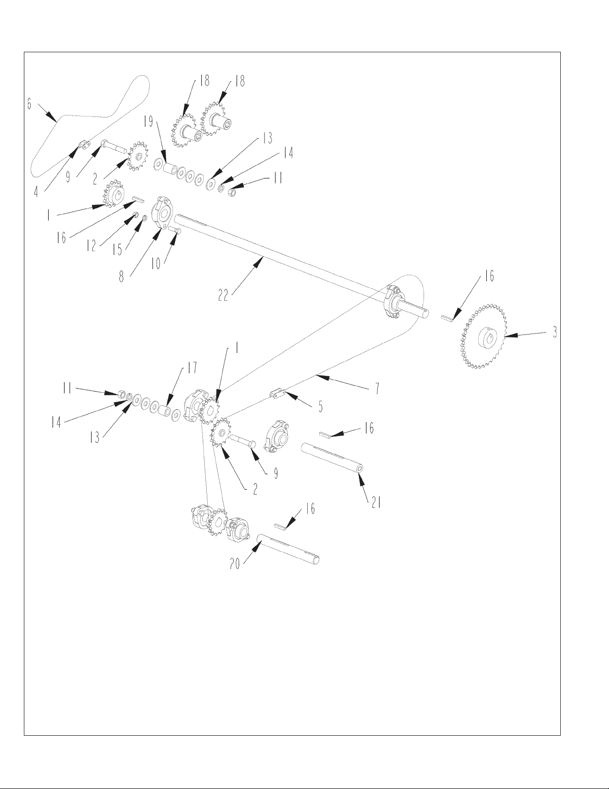
107C DRIVE ASSEMBLY
60
77C/107C DRILLS PARTS REFERENCE

107C DRIVE ASSEMBLY
ITEM PART QTY. PART DESCRIPTION
1 1000029 3 SPKT\50\B\14\1\1/4KW
2 1000039 2 SPKT\50\15\1/2\IDLER
3 1000075 1 SPKT\50\B\36\1\1/4KW
4 1100227 1 CHAIN\50NP\CL
5 1100230 1 CHAIN\A2050NP\CL
6 1100234 1 CHAIN\50NP\73
7 1100283 1 CHAIN\2050NP\85
8 2000310 6 BRG\FLG\CAST\1\2BOLT
9 4800068 2 BOLT\HEX\1/2X3
10 4800098 12 BOLT\HEX\3/8X1-1/4\NC
11 4900001 2 NUT\HEX\1/2\NC
12 4900002 12 NUT\HEX\3/8\NC
13 5000004 10 WASH\FLAT\1/2
14 5000006 2 WASH\LOCK\1/2
15 5000019 12 WASH\LOCK\3/8
16 6200005 4 KEY\SQ\1/4X1-1/2
17 8400058 1 SPCR\DRV\1ODX.640IDX1L\>
18 8400071 2 SPKT\DRIVE\W/SQ_HL_SLV
19 8400073 1 SPCR\DRV\1ODX.640IDX1.25L
20 8400415 1 SHFT\1ST\1X8-3/4\1000
21 8400446 1 SHFT\1X8-1/2\ACRECTR
22 8400573 1 SHFT\DR\TANK\1X38
77C/107C DRILLS PARTS REFERENCE
61

77C & 107C DRIVE WHEEL ASSEMBLY
62
77C/107C DRILLS PARTS REFERENCE

77C & 107C DRIVE WHEEL ASSEMBLY
ITEM PART QTY. PART DESCRIPTION
1 2000310 2 BRG\FLG\CAST\1\2BOLT
2 2600055 1 TIRE\4.8X12\LUG\4PLY
3 2600651 1 WHL\12X4\4HL\RIM
2600865 WHL\ASSY\20X8-10\4HL\4CRL (includes # 2 & #3)
4 3600008 2 CROSS BEARING KIT
5 3600242 2 1” YOKE
6 3600254 1 FEMALE HALF FOR 3600241
7 3600253 1 MALE HALF FOR 3600241
3600241 SHFT\DRV\CMPLT\TR6NA (includes #4, #5, #6 & #7)
8 3800082 2 FTG\LUB\1/4NFXZERK\ADAPT
9 4800080 3 BOLT\HEX\1/2X7
10 4800082 4 BOLT\HEX\1/2X1-1/2
11 4800098 4 BOLT\HEX\3/8X1-1/4\NC
12 4800626 1 BOLT\HEX\1X11\NC
13 4900001 3 NUT\HEX\1/2\NC
14 4900002 4 NUT\HEX\3/8\NC
15 4900005 3 NUT\HEX\5/8\NC
16 4900014 4 NUT\TPLCK\1/2\NC
17 4900015 1 NUT\NYLCK\1\NC
18 5000002 1 WASH\FLAT\5/8
19 5000006 3 WASH\LOCK\1/2
20 5000019 4 WASH\LOCK\3/8
21 6100032 1 SPG\COMP\2.81OD\.406WD>
22 8400024 1 ROD\SPRG\WHL\DR
23 8400025 1 GUIDE\SPRING\LONG
24 8400026 1 GUIDE\SPRING\SHORT
25 8400792 1 SHFT\DR\WHL\13”
26 8400793 1 BRKT\FRK\WHL\DRV\16-1/2X10-1/8
27 8400797 1 FRM\WHL\DR\WELD
28 D8400023 2 PL\MNT\WHL\DR
8400794 WHL\DR\ASSY\107C
77C/107C DRILLS PARTS REFERENCE
63
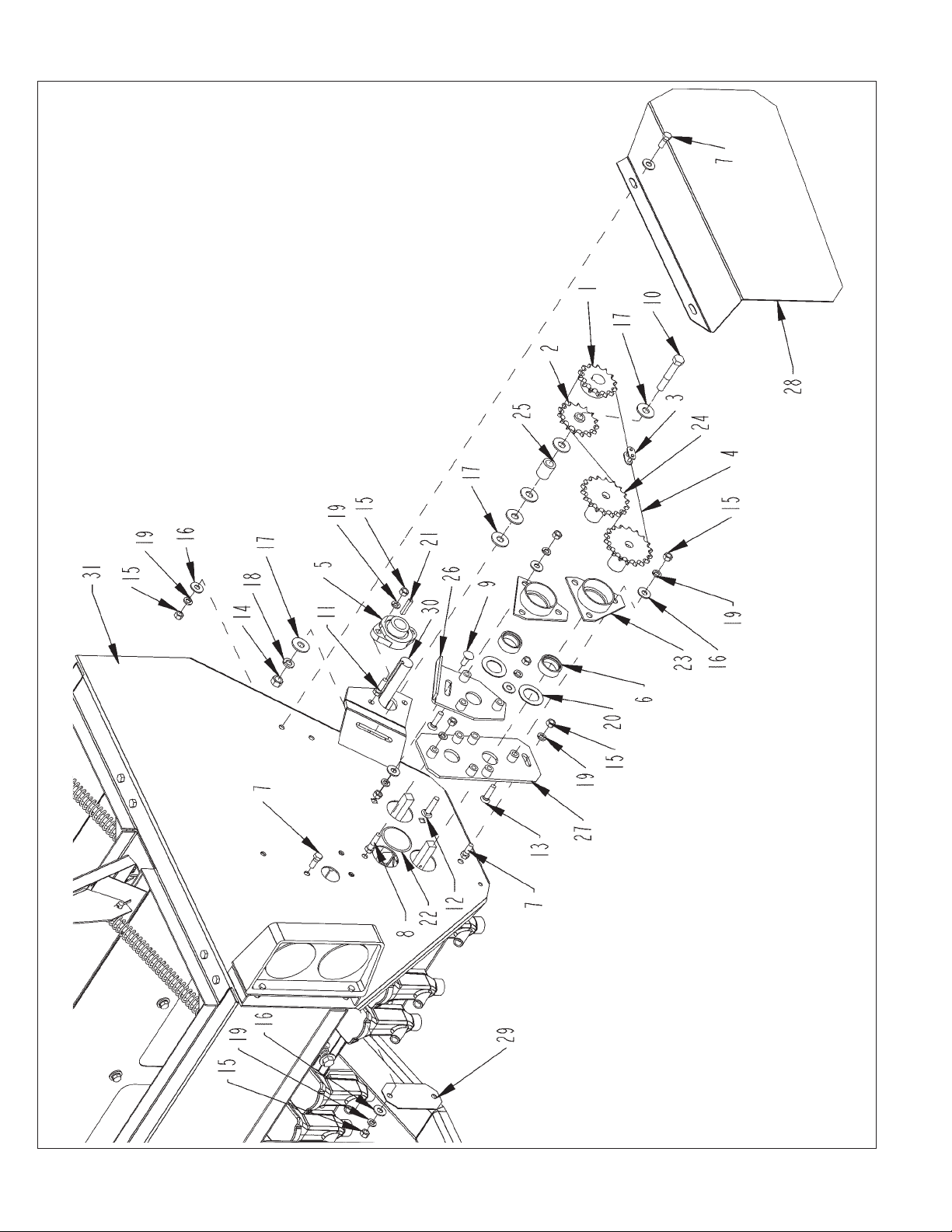
TANK END DRIVE (77C & 107C)
64
77C/107C DRILLS PARTS REFERENCE

TANK END DRIVE (77C & 107C)
ITEM PART QTY. PART DESCRIPTION
1 1000029 1 SPKT\50\B\14\1\1/4KW
2 1000039 1 SPKT\50\15\1/2\IDLER
3 1100227 1 CHAIN\50NP\CL
4 1100234 1 CHAIN\50NP\73
5 2000310 1 BRG\FLG\CAST\1\2BOLT
6 2000824 2 CLLR\BRG\1-1/4 - FOR 8400070
7 4800003 3 BOLT\HEX\3/8X1
8 4800034 1 BOLT\HEX\3/8X1-1/2
9 4800053 1 BOLT\CRG\3/8X1\NC
10 4800068 1 BOLT\HEX\1/2X3
11 4800098 4 BOLT\HEX\3/8X1-1/4\NC
12 4800168 1 BOLT\CRG\3/8X1-3/4\NC
13 4800230 5 SCR\CSK\ALN\3/8X1-1/2\NC
14 4900001 1 NUT\HEX\1/2\NC
15 4900002 15 NUT\HEX\3/8\NC
16 5000001 2 WASH\FLAT\3/8
17 5000004 6 WASH\FLAT\1/2
18 5000006 1 WASH\LOCK\1/2
19 5000019 15 WASH\LOCK\3/8
20 5000084 2 2”PD 1-1/4ID OILITE WASHR
21 6200005 1 KEY\SQ\1/4X1-1/2
22 7500515 2 PLASTIC PLUG 107 DRILL
23 8400070 2 BRG\1-1/4\W/BRKT\3-HL
24 8400071 2 SPKT\DRIVE\W/SQ_HL_SLV
25 8400073 1 SPCR\DRV\1ODX.640IDX1.25L
26 8400074 1 PL\SEAL\TANK\DRILL
27 8400242 1 PL\SEAL\TANK\107
28 8400243 1 SHLD\DR\AGTTR\SGL
29 8400274 1 PLUG\TANK\STL\107DRILL
30 8400573 1 SHFT\DR\TANK\1X38 (107C DRILL)
30A 8400738 1 SHFT\DRV\77\NTV_GR\1X23.5 (77C DRILL)
31 8400801 1 TANK\WLDMNT\107C
31A 8400802 1 TANK\WLDMNT\77C
77C/107C DRILLS PARTS REFERENCE
65

RUN ASSEMBLY (77C & 107C)
66
77C/107C DRILLS PARTS REFERENCE

RUN ASSEMBLY (77C & 107C)
ITEM PART QTY. PART DESCRIPTION
1 2000031 2 BRG\ROW\DBL
2 4800063 1 BOLT\HEX\3/4X4
3 4800071 1 BOLT\HEX\5/16X1-1/4
4 4800076 1 PIN\KLIK\5/16
5 4800079 2 BOLT\HEX\5/8X2-1/2
6 4800082 4 BOLT\HEX\1/2X1-1/2
7 4800231 1 BOLT\HEX\1/2X3-3/4
8 4800984 5 BOLT\HEX\5/8X5-1/2\SHRT\THRD
9 4900003 1 NUT\HEX\5/16\NC
10 4900005 2 NUT\HEX\5/8\NC
11 4900012 7 NUT\TPLCK\5/8\NC
12 4900014 11 NUT\TPLCK\1/2\NC
13 4900139 1 NUT\TPLCK\3/4\GR8\NC
14 5000002 3 WASH\FLAT\5/8
15 5000005 10 WASH\FLAT\3/4
16 5000009 6 WASH\1” OD\ SHIM
17 5000022 1 WASH\LOCK\5/16
18 5000023 1 WASH\FLAT\5/16
19 6100032 1 SPG\COMP\2.81OD\.406WD>
20 7400258 2 CAP\DUST
21 7400264 2 CAP\WHL\W/O_PILOT
22 7500097 2 CONVOLUTED HOSE
23 7500098 2 CLAMP\SDHOSE\1-1/4\A-24
24 7500160 2 #6610 BREAING BUSHING
25 7500187 1 BLADE\ASSY\14”\COULTER
26 7500188 1 BLADE\ASSY\DISC\14”
27 7500307 2 CAP\SPACER\BUSHING
28 8400025 1 GUIDE\SPRING\LONG
29 8400026 1 GUIDE\SPRING\SHORT
30 8400047 1 ROD\SPG\5/8X15
31 8400064 1 ROD\DEPTH\WHEEL\PACKER
32 8400271 1 BRKT\WHL\PACKER\20”
33 8400617 1 WHL\PRESS\STL\ASSY
34 8400670 2 SCRPR\DISC
35 8400692 1 FRM\RUN\LOWER\CAST
36 8400693 1 LINK\RUN\LOWER\CAST
37 8400694 1 LINK\RUN\UPPER\CAST
38 8400697 1 FRM\RUN\FR\CAST
39 8400736 1 BOOT\DR\SUB_WELD\LH\#10
39a 8400737 1 BOOT\DR\SUB_WELD\RH\#12
8400780 RUN\DRILL\STL\RH\CAST\ASSY
8400781 RUN\DRILL\STL\LH\CAST\ASSY
77C/107C DRILLS PARTS REFERENCE
67

77C TANK ASSEMBLY - FRONT (FOR S.N. UP TO 0075)
68
77C/107C DRILLS PARTS REFERENCE

77C TANK ASSEMBLY - FRONT (FOR S.N. UP TO 0075)
ITEM PART QTY. PART DESCRIPTION
1 3800082 6 FTG\LUB\1/4NFXZERK\ADAPT
2 4800012 12 BOLT\CRG\3/8X1-1/4\NC
3 4800053 13 BOLT\CRG\3/8X1\NC
4 4800164 20 BOLT\HEX\3/8X3/4
5 4801296 48 BOLT\FLG\SERR\5/16X1/2
6 4900002 49 NUT\HEX\3/8\NC
7 5000001 73 WASH\FLAT\3/8
8 5000019 69 WASH\LOCK\3/8
9 5000055 6 WASH\SPINDLE\7/8
10 7500108 6 HSG\CAST\BUSH\TANK\DRILL
11 7500562 4 SLV\SQ_HL\5/8X1-7/16\W/5/16_PLAIN
12 7501058 4 SUP\SHFT\ASSY\SLEEVE(INCLUDES 3800082, 5000055, 7500108, 7500562)
13 7501400 24 FNNL\SEED\SMALL\77-107
14 7501401 24 FNNL\COVER\SEED\SMALL\77-107
15 7501444 24 #5\CAPLUG
16 8400243 1 SHLD\DR\AGTTR\SGL
17 8400658 1 WHL\FEED\33-1/16\FR\CTR(COMPLETE)
17A 8400423 SHFT\TANK\33-1/16\DRILL(SHAFT ONLY)
18 8400704 2 PL\CLEANOUT\TANK
19 8400705 1 PL\CNTRL\7” SPACING
20 8400707 1 WHL\FEED\23-15/16\FR\RH(COMPLETE)
20A 8400708 SHFT\TANK\23-15/16\DRILL(SHAFT ONLY)
21 8400709 1 WHL\FEED\19”\FR\LH(COMPLETE)
21A 8400710 SHFT\TANK\19”\DRILL(SHAFT ONLY)
22 8400717 2 COV\DIVIDER\SH\37.25X10.5(THRU S.N. 0075)
23 8400771 2 CUP\SEED\CNTR\FRNT\ASM
NOT SHOWN
4800169 2 PIN\RLLD\1/4X1-1/8
7500109 2 SLV\SQ_HL\5/8X1-7/16\W/5/16_THRU_HL
77C/107C DRILLS PARTS REFERENCE
69

77C TANK ASSEMBLY - FRONT (FOR S.N. 0076 AND UP)
70
77C/107C DRILLS PARTS REFERENCE

77C TANK ASSEMBLY - FRONT (FOR S.N. 0076 AND UP)
ITEM PART QTY. PART DESCRIPTION
1 3800082 6 FTG\LUB\1/4NFXZERK\ADAPT
2 4800012 12 BOLT\CRG\3/8X1-1/4\NC
3 4800053 13 BOLT\CRG\3/8X1\NC
4 4800169 2 PIN\RLLD\1/4X1-1/8
5 4801296 48 BOLT\FLG\SERR\5/16X1/2
6 4900002 49 NUT\HEX\3/8\NC
7 5000001 51 WASH\FLAT\3/8
8 5000019 49 WASH\LOCK\3/8
9 5000055 6 WASH\SPINDLE\7/8
10 7500108 6 HSG\CAST\BUSH\TANK\DRILL
11 7500109 2 SLV\SQ_HL\5/8X1-7/16\W/5/16_THRU_HL
12 7500110 2 SUP\SHFT\ASSY\SLEEVE\107
(INCLUDES 3800082, 4800169, 5000055, 7500108, 7500109)
13 7500562 4 SLV\SQ_HL\5/8X1-7/16\W/5/16_PLAIN
14 7501058 4 SUP\SHFT\ASSY\SLEEVE\107
(INCLUDES 3800082, 5000055, 7500108, 7500562)
15 7501400 24 FNNL\SEED\SMALL\77-107
16 7501401 24 FNNL\COVER\SEED\SMALL\77-107
17 7501444 24 #5\CAPLUG
18 8400243 1 SHLD\DR\AGTTR\SGL
19 8400658 1 WHL\FEED\33-1/16\FR\CTR (COMPLETE)
19A 8400423 SHFT\TANK\33-1/16\DRILL(SHAFT ONLY)
20 8400704 2 PL\CLEANOUT\TANK
21 8400705 1 PL\CNTRL\7” SPACING
22 8400707 1 WHL\FEED\23-15/16\FR\RH (COMPLETE)
22A 8400708 SHFT\TANK\23-15/16\DRILL(SHAFT ONLY)
23 8400709 1 WHL\FEED\19”\FR\LH (COMPLETE)
23A 8400710 SHFT\TANK\19”\DRILL(SHAFT ONLY)
24 8400771 2 CUP\SEED\CNTR\FRNT\ASM
77C/107C DRILLS PARTS REFERENCE
71
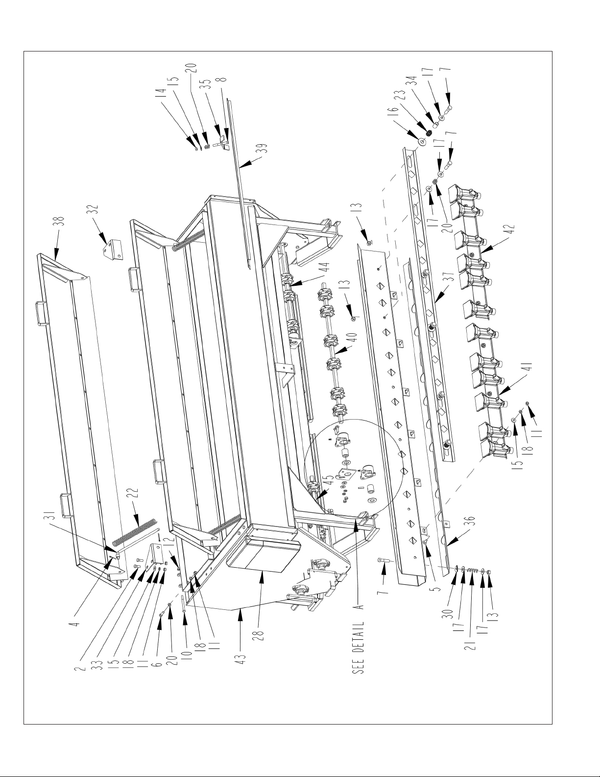
77C TANK ASSEMBLY - BACK
72
77C/107C DRILLS PARTS REFERENCE

77C TANK ASSEMBLY - BACK
ITEM PART QTY. PART DESCRIPTION
1 3800082 6 FTG\LUB\1/4NFXZERK\ADAPT
2 4800003 15 BOLT\HEX\3/8X1
3 4800012 12 BOLT\CRG\3/8X1-1/4\NC
4 4800044 8 PIN\COT\5/32X1-1/2
5 4800053 13 BOLT\CRG\3/8X1\NC
6 4800098 4 BOLT\HEX\3/8X1-1/4\NC
7 4800114 21 BOLT\HEX\1/2X2
8 4800156 6 BOLT\HEX\3/8X3
9 4800169 2 PIN\RLLD\1/4X1-1/8
10 4800170 6 BOLT\HEX\5/16X3-1/2
11 4900002 49 NUT\HEX\3/8\NC
12 4900003 18 NUT\HEX\5/16\NC
13 4900014 21 NUT\TPLCK\1/2\NC
14 4900030 6 NUT\NYLCK\3/8\NC
15 5000001 51 WASH\FLAT\3/8
16 5000002 6 WASH\FLAT\5/8
17 5000016 36 WASH\FLAT\7/16
18 5000019 49 WASH\LOCK\3/8
19 5000055 6 WASH\SPINDLE\7/8
20 5000128 4 WASH\FLAT\3/8\RBBR\EPDM
21 6100002 8 SPRING\COMP\.072W\11/16OD\2-1/8LONG
22 6100017 4 PRESSURE SPRING 12X1 1/8
23 6100031 6 SPRING\COMP\.072W\25/32OD
24 7500108 6 HSG\CAST\BUSH\TANK\DRILL
25 7500109 2 SLV\SQ_HL\5/8X1-7/16\W/5/16_THRU_HL
26 7500110 2 SUP\SHFT\ASSY\SLEEVE\107
(INCLUDES 3800082, 4800169, 5000055, 7500108, 7500109)
27 7500562 4 SLV\SQ_HL\5/8X1-7/16\W/5/16_PLAIN
28 7500590 1 ENCL\OPS\8-1/2X11X1-5/8
(THRU S.N. 0115, LATER MACHINES USE MANUAL CANISTER)
29 7501058 4 SUP\SHFT\ASSY\SLEEVE\107
(INCLUDES 3800082, 5000055, 7500108, 7500562)
30 8300236 8 WASH\BENT\1/2”
31 8400003 4 ROD\COV\TANK\SPG
32 8400005 2 RTNR\TANK\COVER\SPG\RH
33 8400004 2 RTNR\TANK\COVER\SPG\LH
34 8400007 6 GUIDE\PL\CNTRL\107
35 8400011 6 CLMP\WHL\COV\HOLD DOWN
36 8400704 2 PL\CLEANOUT\TANK
37 8400706 1 PL\CNTRL\7”SPACING
38 8400716 2 COV\TANK\BANDING
39 8400719 4 COV\WHL\FEED\77
40 8400762 1 WHL\FEED\3S\33-1/16\REAR\CTR (COMPLETE)
40A 8400423 SHFT\TANK\33-1/16\DRILL(SHAFT ONLY)
41 8400773 1 CUP\SEED\CNTR\LT\REAR\ASM
42 8400774 1 CUP\SEED\CNTR\RT\REAR\ASM
43 8400802 1 TANK\WLDMNT\77C
44 8400803 1 WHL\FEED\3S\23-15/16\REAR\RH (COMPLETE)
44A 8400708 SHFT\TANK\23-15/16\DRILL(SHAFT ONLY)
45 8400804 1 WHL\FEED\3S\19\REAR\LH (COMPLETE)
45A 8400710 SHFT\TANK\19”\DRILL(SHAFT ONLY)
77C/107C DRILLS PARTS REFERENCE
73
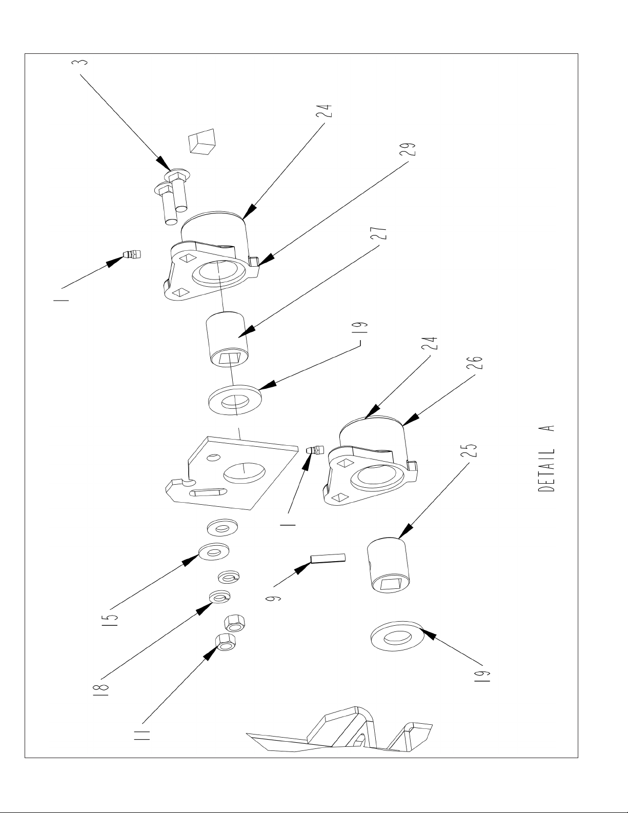
77C TANK ASSEMBLY - BACK - DETAIL A
74
77C/107C DRILLS PARTS REFERENCE

77C TANK ASSEMBLY - BACK - DETAIL A
ITEM PART QTY. PART DESCRIPTION
1 3800082 6 FTG\LUB\1/4NFXZERK\ADAPT
2 4800003 15 BOLT\HEX\3/8X1
3 4800012 12 BOLT\CRG\3/8X1-1/4\NC
4 4800044 8 PIN\COT\5/32X1-1/2
5 4800053 13 BOLT\CRG\3/8X1\NC
6 4800098 4 BOLT\HEX\3/8X1-1/4\NC
7 4800114 21 BOLT\HEX\1/2X2
8 4800156 6 BOLT\HEX\3/8X3
9 4800169 2 PIN\RLLD\1/4X1-1/8
10 4800170 6 BOLT\HEX\5/16X3-1/2
11 4900002 49 NUT\HEX\3/8\NC
12 4900003 18 NUT\HEX\5/16\NC
13 4900014 21 NUT\TPLCK\1/2\NC
14 4900030 6 NUT\NYLCK\3/8\NC
15 5000001 51 WASH\FLAT\3/8
16 5000002 6 WASH\FLAT\5/8
17 5000016 36 WASH\FLAT\7/16
18 5000019 49 WASH\LOCK\3/8
19 5000055 6 WASH\SPINDLE\7/8
20 5000128 4 WASH\FLAT\3/8\RBBR\EPDM
21 6100002 8 SPRING\COMP\.072W\11/16OD\2-1/8LONG
22 6100017 4 PRESSURE SPRING 12X1 1/8
23 6100031 6 SPRING\COMP\.072W\25/32OD
24 7500108 6 HSG\CAST\BUSH\TANK\DRILL
25 7500109 2 SLV\SQ_HL\5/8X1-7/16\W/5/16_THRU_HL
26 7500110 2 SUP\SHFT\ASSY\SLEEVE\107
(INCLUDES 3800082, 4800169, 5000055, 7500108, 7500109)
27 7500562 4 SLV\SQ_HL\5/8X1-7/16\W/5/16_PLAIN
28 7500590 1 ENCL\OPS\8-1/2X11X1-5/8
(THRU S.N. 0115, LATER MACHINES USE MANUAL CANISTER)
29 7501058 4 SUP\SHFT\ASSY\SLEEVE\107 (INCLUDES 3800082, 5000055, 7500108, 7500562)
30 8300236 8 WASH\BENT\1/2”
31 8400003 4 ROD\COV\TANK\SPG
32 8400005 2 RTNR\TANK\COVER\SPG\RH
33 8400004 2 RTNR\TANK\COVER\SPG\LH
34 8400007 6 GUIDE\PL\CNTRL\107
35 8400011 6 CLMP\WHL\COV\HOLD DOWN
36 8400704 2 PL\CLEANOUT\TANK
37 8400706 1 PL\CNTRL\7”SPACING
38 8400716 2 COV\TANK\BANDING
39 8400719 4 COV\WHL\FEED\77
40 8400762 1 WHL\FEED\3S\33-1/16\REAR\CTR (COMPLETE)
40A 8400423 SHFT\TANK\33-1/16\DRILL(SHAFT ONLY)
41 8400773 1 CUP\SEED\CNTR\LT\REAR\ASM
42 8400774 1 CUP\SEED\CNTR\RT\REAR\ASM
43 8400802 1 TANK\WLDMNT\77C
44 8400803 1 WHL\FEED\3S\23-15/16\REAR\RH (COMPLETE)
44A 8400708 SHFT\TANK\23-15/16\DRILL(SHAFT ONLY)
45 8400804 1 WHL\FEED\3S\19\REAR\LH (COMPLETE)
45A 8400710 SHFT\TANK\19”\DRILL(SHAFT ONLY)
77C/107C DRILLS PARTS REFERENCE
75
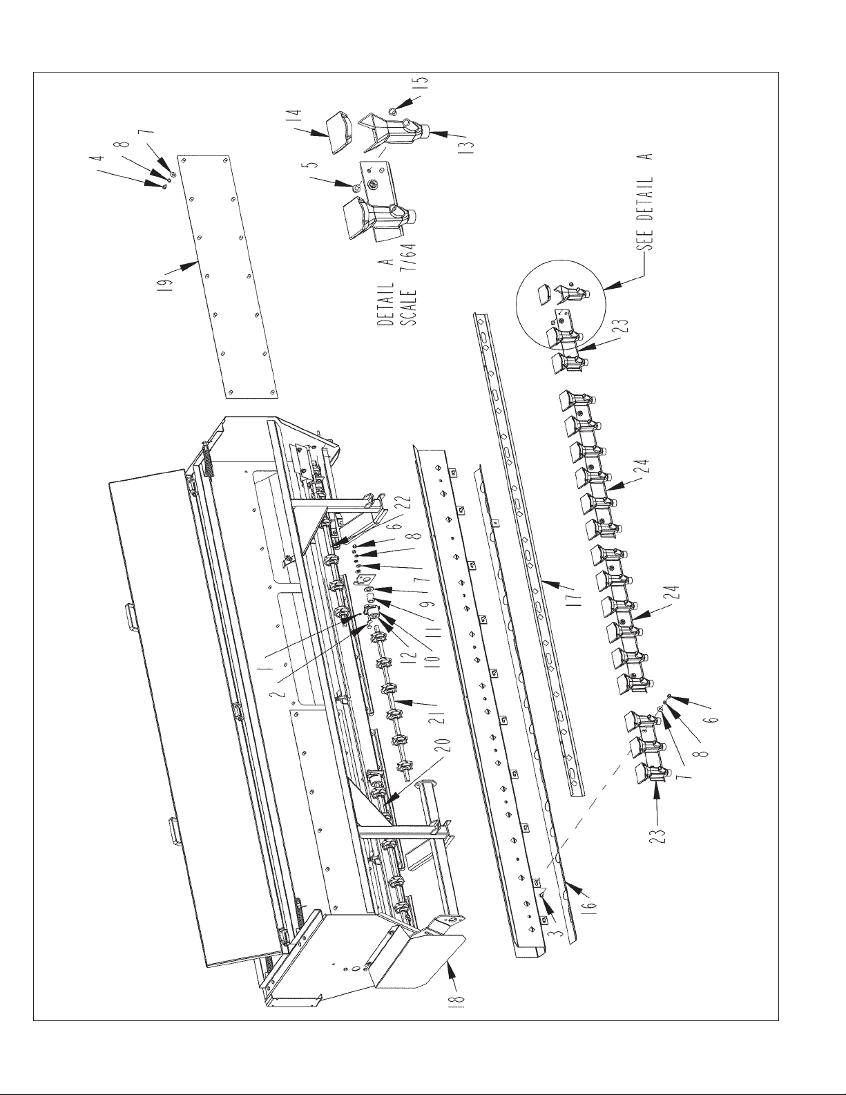
107C TANK ASSEMBLY - FRONT (FOR S.N. UP TO 0500)
76
77C/107C DRILLS PARTS REFERENCE

107C TANK ASSEMBLY - FRONT (FOR S.N. UP TO 0500)
ITEM PART QTY. PART DESCRIPTION
1 3800082 6 FTG\LUB\1/4NFXZERK\ADAPT
2 4800012 12 BOLT\CRG\3/8X1-1/4\NC
3 4800053 21 BOLT\CRG\3/8X1\NC
4 4800164 28 BOLT\HEX\3/8X3/4
5 4801296 72 BOLT\FLG\SERR\5/16X1/2
6 4900002 57 NUT\HEX\3/8\NC
7 5000001 87 WASH\FLAT\3/8
8 5000019 85 WASH\LOCK\3/8
9 5000055 6 WASH\SPINDLE\7/8
10 7500108 6 HSG\CAST\BUSH\TANK\DRILL
11 7500562 4 SLV\SQ_HL\5/8X1-7/16\W/5/16_PLAIN
12 7501058 4 SUP\SHFT\ASSY\SLEEVE\107
(INCLUDES 3800082, 5000055, 7500108, 7500562)
13 7501400 36 FNNL\SEED\SMALL\77-107
14 7501401 36 FNNL\COVER\SEED\SMALL\77-107
15 7501444 36 #5\CAPLUG
16 8400110 2 PL\CLEANOUT\TANK
17 8400114 1 PL\CNTRL\7” SPACING
18 8400243 1 SHLD\DR\AGTTR\SGL
19 8400318 2 COV\DIVIDER\107
20 8400656 1 WHL\FEED\38-7/16\FR\RH (COMPLETE)
20A 8400426 SHFT\TANK\38-7/16\DRILL(SHAFT ONLY)
21 8400658 1 WHL\FEED\33-1/16\FR\CTR (COMPLETE)
21A 8400423 SHFT\TANK\33-1/16\DRILL(SHAFT ONLY)
22 8400660 1 WHL\FEED\34-1/2\FR\LH (COMPLETE)
22A 8400425 SHFT\TANK\34-1/2\DRILL(SHAFT ONLY)
23 8400770 2 CUP\SEED\END\FRNT\ASM
24 8400771 2 CUP\SEED\CNTR\FRNT\ASM
NOT SHOWN
4800169 2 PIN\RLLD\1/4X1-1/8
7500109 2 SLV\SQ_HL\5/8X1-7/16\W/5/16_THRU_HL
77C/107C DRILLS PARTS REFERENCE
77
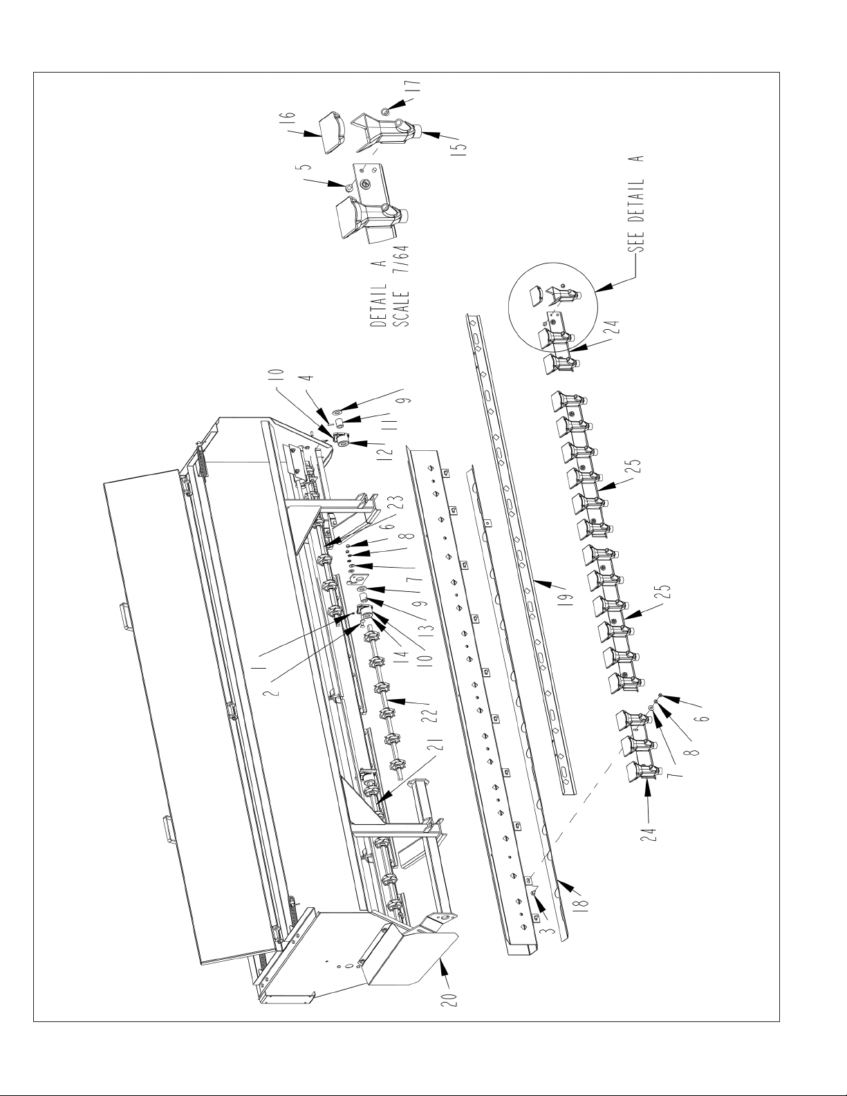
107C TANK ASSEMBLY - FRONT (FOR S.N. 0501 AND UP)
78
77C/107C DRILLS PARTS REFERENCE

107C TANK ASSEMBLY - FRONT (FOR S.N. 0501 AND UP)
ITEM PART QTY. PART DESCRIPTION
1 3800082 6 FTG\LUB\1/4NFXZERK\ADAPT
2 4800012 12 BOLT\CRG\3/8X1-1/4\NC
3 4800053 21 BOLT\CRG\3/8X1\NC
4 4800169 2 PIN\RLLD\1/4X1-1/8
5 4801296 72 BOLT\FLG\SERR\5/16X1/2
6 4900002 57 NUT\HEX\3/8\NC
7 5000001 59 WASH\FLAT\3/8
8 5000019 57 WASH\LOCK\3/8
9 5000055 6 WASH\SPINDLE\7/8
10 7500108 6 HSG\CAST\BUSH\TANK\DRILL
11 7500109 2 SLV\SQ_HL\5/8X1-7/16\W/5/16_THRU_HL
12 7500110 2 SUP\SHFT\ASSY\SLEEVE\107
(INCLUDES 3800082, 4800169, 5000055, 7500108, 7500109)
13 7500562 4 SLV\SQ_HL\5/8X1-7/16\W/5/16_PLAIN
14 7501058 4 SUP\SHFT\ASSY\SLEEVE\107
(INCLUDES 3800082, 5000055, 7500108, 7500562)
15 7501400 36 FNNL\SEED\SMALL\77-107
16 7501401 36 FNNL\COVER\SEED\SMALL\77-107
17 7501444 36 #5\CAPLUG
18 8400110 2 PL\CLEANOUT\TANK
19 8400114 1 PL\CNTRL\7” SPACING
20 8400243 1 SHLD\DR\AGTTR\SGL
21 8400656 1 WHL\FEED\38-7/16\FR\RH
21A 8400426 SHFT\TANK\38-7/16\DRILL(SHAFT ONLY)
22 8400658 1 WHL\FEED\33-1/16\FR\CTR
22A 8400423 SHFT\TANK\33-1/16\DRILL(SHAFT ONLY)
23 8400660 1 WHL\FEED\34-1/2\FR\LH
23A 8400425 SHFT\TANK\34-1/2\DRILL(SHAFT ONLY)
24 8400770 2 CUP\SEED\END\FRNT\ASM
25 8400771 2 CUP\SEED\CNTR\FRNT\ASM
77C/107C DRILLS PARTS REFERENCE
79
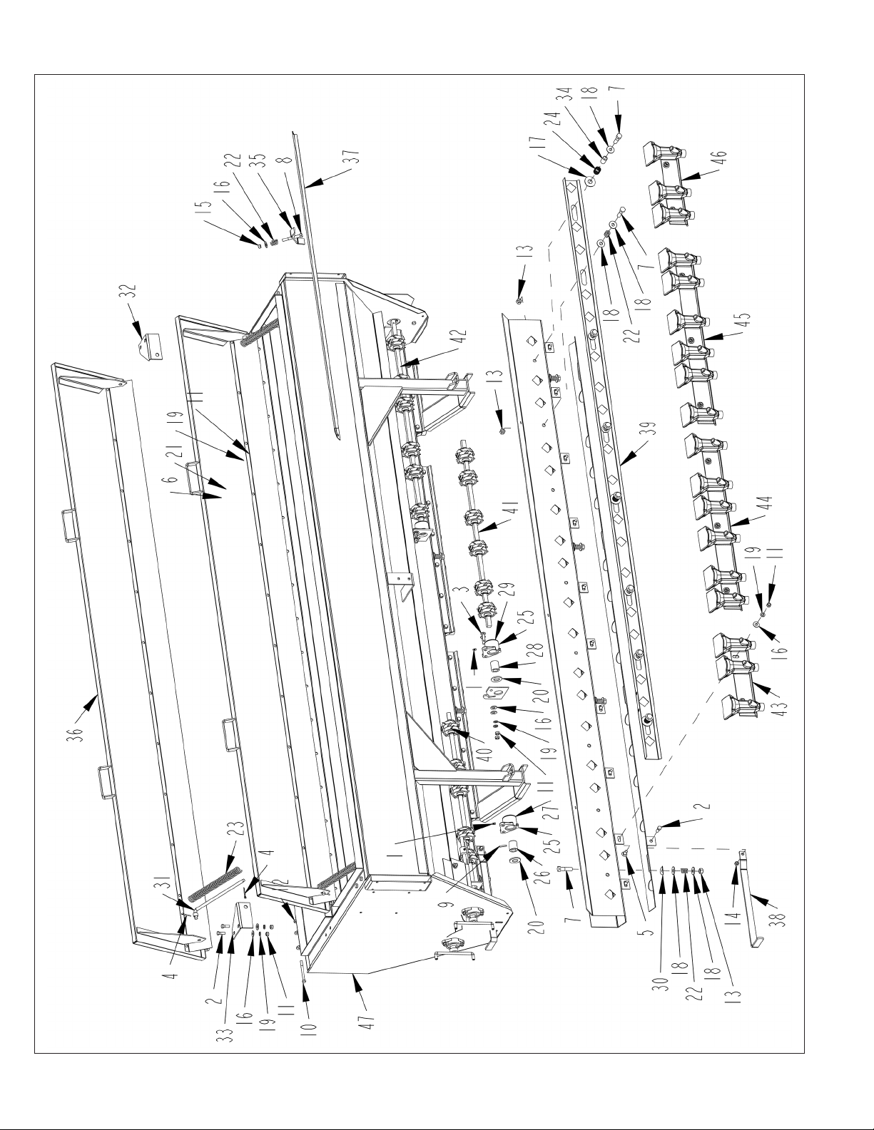
107C TANK ASSEMBLY - BACK
80
77C/107C DRILLS PARTS REFERENCE

107C TANK ASSEMBLY - BACK
ITEM PART QTY. PART DESCRIPTION
1 3800082 6 FTG\LUB\1/4NFXZERK\ADAPT
2 4800003 15 BOLT\HEX\3/8X1
3 4800012 12 BOLT\CRG\3/8X1-1/4\NC
4 4800044 8 PIN\COT\5/32X1-1/2
5 4800053 21 BOLT\CRG\3/8X1\NC
6 4800098 4 BOLT\HEX\3/8X1-1/4\NC
7 4800114 25 BOLT\HEX\1/2X2
8 4800156 6 BOLT\HEX\3/8X3
9 4800169 2 PIN\RLLD\1/4X1-1/8
10 4800170 6 BOLT\HEX\5/16X3-1/2
11 4900002 57 NUT\HEX\3/8\NC
12 4900003 18 NUT\HEX\5/16\NC
13 4900014 25 NUT\TPLCK\1/2\NC
14 4900023 2 NUT\TPLCK\3/8\NC
15 4900030 6 NUT\NYLCK\3/8\NC
16 5000001 59 WASH\FLAT\3/8
17 5000002 6 WASH\FLAT\5/8
18 5000004 44 WASH\FLAT\1/2
19 5000019 57 WASH\LOCK\3/8
20 5000055 6 WASH\SPINDLE\7/8
21 5000128 4 WASH\FLAT\3/8\RBBR\EPDM
22 6100002 25 SPRING\COMP\.072W\11/16OD\2-1/8LONG
23 6100017 4 PRESSURE SPRING 12X1 1/8
24 6100031 6 SPRING\COMP\.072W\25/32OD
25 7500108 6 HSG\CAST\BUSH\TANK\DRILL
26 7500109 2 SLV\SQ_HL\5/8X1-7/16\W/5/16_THRU_HL
27 7500110 2 SUP\SHFT\ASSY\SLEEVE\107
(INCLUDES 3800082, 4800169, 5000055, 7500108, 7500109)
28 7500562 4 SLV\SQ_HL\5/8X1-7/16\W/5/16_PLAIN
29 7501058 4 SUP\SHFT\ASSY\SLEEVE\107(INCLUDES 3800082, 5000055, 7500108, 7500562)
30 8300236 8 WASH\BENT\1/2”
31 8400003 4 ROD\COV\TANK\SPG
32 8400005 2 RTNR\TANK\COVER\SPG\RH
33 8400004 2 RTNR\TANK\COVER\SPG\LH
34 8400007 6 GUIDE\PL\CNTRL\107
35 8400011 6 CLMP\WHL\COV\HOLD DOWN
36 8400107 2 COV\TANK\BANDING\107
37 8400111 4 COV\WHL\FEED\107\S/N2672\107
38 8400112 2 HDL\PL_CLEANOUT
39 8400245 1 PL\CNTRL\7”SPACING
40 8400761 1 WHL\FEED\3S\34-1/2\REAR\LH (COMPLETE)
40A 8400425 SHFT\TANK\34-1/2\DRILL(SHAFT ONLY)
41 8400762 1 WHL\FEED\3S\33-1/16\REAR\CTR (COMPLETE)
41A 8400423 SHFT\TANK\33-1/16\DRILL(SHAFT ONLY)
42 8400763 1 WHL\FEED\3S\38-7/16\REAR\RH (COMPLETE)
42A 8400426 SHFT\TANK\38-7/16\DRILL(SHAFT ONLY)
43 8400772 1 CUP\SEED\END\LT\REAR\ASM
44 8400773 1 CUP\SEED\CNTR\LT\REAR\ASM
45 8400774 1 CUP\SEED\CNTR\RT\REAR\ASM
46 8400775 1 CUP\SEED\END\RT\REAR\ASM
47 8400801 1 TANK\WLDMNT\107C
77C/107C DRILLS PARTS REFERENCE
81

SEED & FERTILIZER SETTING ASSEMBLY
ITEM PART QTY. PART DESCRIPTION
1 2000313 1 BRG\FLG\CAST\3/4\2BOLT
2 3600053 1 FTG\LUB\1/4NFXZERK\ADAPT
3 4800013 2 BOLT\HEX\5/16X1
4 4800153 4 BOLT\CRG\5/16X3/4\NC
5 4900003 6 NUT\HEX\5/16\NC
6 5000022 4 WASH\LOCK\5/16
7 5000023 4 WASH\FLAT\5/16
8 7500071 1 CALIBRATION POINTER NUT
9 7500072 1 CALIBRATION CONTRL PL NUT
10 7500073 1 CALIBRATION SHAFT #6620
11 8400060 1 HDL\CAL
12 8400262 1 PL\DECAL\CAL\DUAL_USE\107
NOT SHOWN
6500016 DECAL\INFO\CAL;SCALE;GRAN
6500017 DECAL\INFO\CAL.SCALE;FERT
6500081 DECAL\INFO\CAL.SCALE;>
82
77C/107C DRILLS PARTS REFERENCE

SCRAPER ASSEMBLY
ITEM PART QTY. PART DESCRIPTION
8400091 Scraper Assembly - Complete
1 8400670 2 Scraper\Disc
2 4800071 1 5/16” x 1-1/4” Bolt
3 5000023 1 5/16” Flat Washer
4 5000022 1 5/16” Lock Washer
5 4900003 1 5/16” Hex Nut
77C/107C DRILLS PARTS REFERENCE
83

FEED WHEEL - DOUBLE
ITEM PART QTY. PART DESCRIPTION
1 7400066 4 CLIP\RETAINER\WHL\FEED
2 7500007 1 WHL\FEED\LH
3 7500008 1 WHL\FEED\RH
4 7500107 1 CLMP\HOSE
7500006 WHL\FERT\TANK(INCLUDES ALL ABOVE)
84
77C/107C DRILLS PARTS REFERENCE
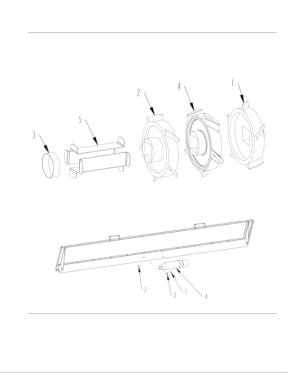
FEED WHEEL - TRIPLE
ITEM PART QTY. PART DESCRIPTION
1 7500007 1 WHL\FEED\LH
2 7500008 1 WHL\FEED\RH
3 7500107 1 CLMP\HOSE
4 7501388 1 WHL\FEED\CENTER
5 7501407 4 CLIP\RETAINER\WHL\FEED\TRIPLE
7501453 WHL\FEED\TRIPLE(INCLUDES ALL ABOVE)
MANUAL CANISTER
ITEM PART QTY. PART DESCRIPTION
1 4800643 3 BOLT\HEX\5/16X3/4
2 4900108 3 NUT\FLG\SERR\5/16\NC
3 5000023 3 WASH\FLAT\5/16
4 7501628 1 CNSTRS\MANUAL\12X3.5
77C/107C DRILLS PARTS REFERENCE
85

COULTER & DISK ASSEMBLY
ITEM PART NO. QTY. DESCRIPTION
1 7500064 1 Coulter, 14” - 6 Hole
2 2000031 1 Brg.
3 7500165 1 Cage
4 4800161 6 1/2” - 13 x 1”
Button Hd. Socket Screw
5 4900014 6 Lock Nut, 1/2”
6 7500187 1 Coulter (Complete)
7 7500160 1 Sleeve
8 5000009 2 Shim Washer
ITEM PART NO. QTY. DESCRIPTION
1 7500010 1 Disk, 14”
2 2000031 1 Brg.
3 7500167 1 Cage
4 4800039 12 Rivets, 1/4” x 1/2”
5 7500188 1 Disk (Complete)
6 7500160 1 Sleeve
7 5000009 2 Shim Washers
86
77C/107C DRILLS PARTS REFERENCE

PRESS WHEEL ASSEMBLY
TO RETROFIT DRILL WITH SERIAL NO. 1550 & UP
ORDER PART 8400617 & 4800063
PART NO. QTY. DESCRIPTION
8400617 Press Wheel Assembly
2000061 2 Brg/3/4/FHR204-12
7500653 1 Spcr/Wheel/Packer/107
8400616 1 Whl/Stl; Packer/107
7400264 2 Packer Wheel Cap - No Pilot
4800063 1 Bolt\Hex\3/4 x 4
4900139 1 Nut\Toplock\3/4
77C/107C DRILLS PARTS REFERENCE
87

A Tradition of Innovation Since 1966
88
77C/107C DRILLS PARTS REFERENCE
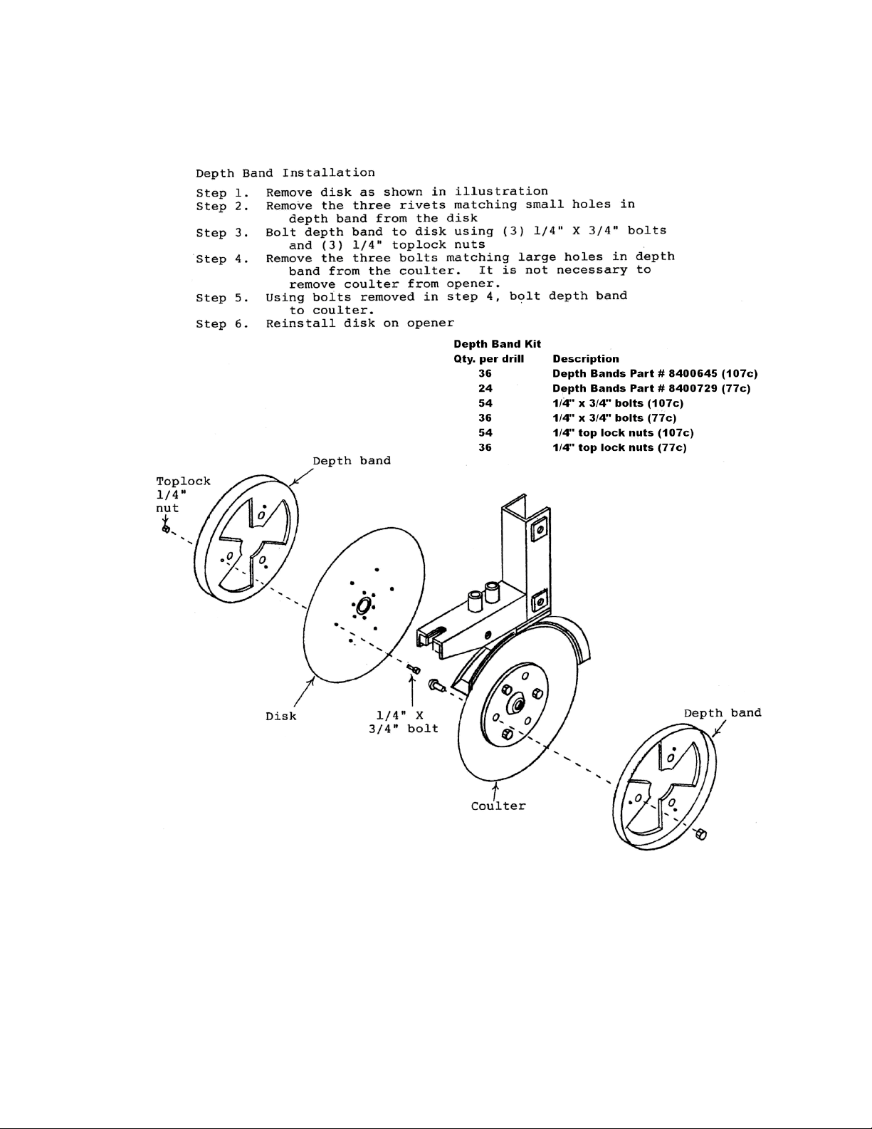
DEPTH BAND INSTALLATION
77C/107C DRILLS PARTS REFERENCE
89
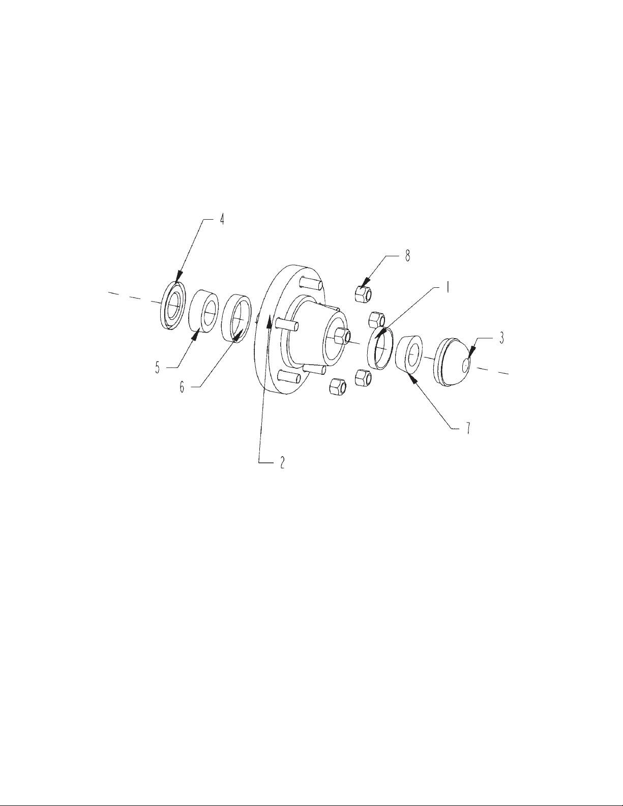
HUB ASSEMBLY
90
77C/107C DRILLS PARTS REFERENCE

HUB ASSEMBLY
ITEM PART QTY. PART DESCRIPTION
1 2900004 1 CUP\INNER\WHEEL HUB
2 2900011 1 HUB\WITH CONES\W/NUTS
3 2900013 1 CAP\DUST\WHL;HUB(DC-13)
4 2900014 1 SEAL\GREASE(517) (15190)
5 2900015 1 CONE\INNER/WHL HUB(48548)
6 2900016 1 CUP\INNER\WHL:HUB(48510
7 2900018 1 CONE\OUTER\WHL;HUB(67048
8 4900094 5 NUT\TAPER\WHEEL\1/2\NF\
77C/107C DRILLS PARTS REFERENCE
91

HUB FORK ASSEMBLY
ITEM PART NO. QTY. DESCRIPTION
1 2900083 6 NUT\WHL\9/16-18\UNF
2 2900085 2 SEAL\WHL;HUB(20078)
3 2900086 2 CONE\2788\WHL;HUB
4 2900087 2 CUP\BRG\HUB\WHL\2720
5 2900089 1 HUB\H-628(FORK)\COMPLETE
6 2900090 6 WHL\BOLT\9/16”X2-1/4”
92
77C/107C DRILLS PARTS REFERENCE
 Loading...