

Duratech Dura Pro 12, Dura Pro 28T, Dura Pro 17, Dura Pro 21, Dura Pro 25 Installation Instructions Manual
Page 1
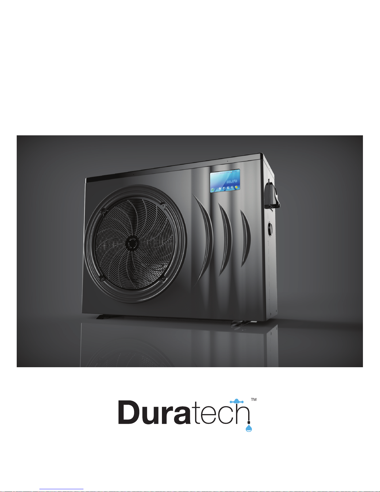
INVERTER HEATPUMP
FOR SWIMMING POOLS
Installation & Instruction Manual
402-0071-161212
heat pumps
Page 2

2
Table of contents
1. Preface
2. Specications
2.1 Performance Data
2.2 Dimensions
3. Installation and Connection
3.1 Heat Pump Location
3.2 How Close to Your Pool?
3.3 Installation illustration
3.4 Installation of a check valve
3.5 Electrical Wiring
3.6 Initial Start-up of the Unit
3.7 Condensation
4. Operation and Use
4.1 Display interface introduction
4.2 Button functions
4.3 Error codes
4.4 Error code list
5. Wiring diagrams
5.1 Wire control interface diagram and denition
5.2 Controller interface diagram and denition
6. Maintenance and Inspection
7.Appendix
7.1 Caution & Warning
7.2 Warranty
3
4
6
8
8
9
9
10
10
11
12
13
17
18
20
20
23
24
25
Page 3

3
1. Preface
In order to provide our customers with quality, reliability and versatility, this product has
been made to strict production standards. This manual includes all the necessary
information about installation, debugging, discharging and maintenance. Please read this
manual carefully before you open or maintain the unit. The manufacture of this product will
not be held responsible if someone is injured or the unit is damaged, as a result of
improper installation, debugging, or unnecessary maintenance. It is vital that the
instructions within this manual are adhered to at all times. The unit must be installed by
qualied personnel.
The unit can only be repaired by qualied personnel or an authorized dealer.
Maintenance and operation must be carried out according to the recommended time and
frequency, as stated in this manual.
Use genuine standard spare parts only.
Failure to comply with these recommendations will invalidate the warranty.
Swimming Pool Heat Pump Unit heats the swimming pool water and keeps the temperature
constant.
Our heat pump has following characteristics:
• Durable
The heat exchanger is made of PVC & Titanium tube which can withstand prolonged
exposure to swimming pool water.
• Installation exibility
The unit can be installed outdoors or indoors.
• Quiet operation
The unit comprises an efcient rotary/ scroll compressor and a low-noise fan motor,
which guarantees its quiet operation.
• Advanced controlling
The unit includes micro-computer controlling, allowing all operation parameters to be
set. Operation status can be displayed on the LCD wire controller. Remote controller
can be chosen as future option.
Page 4
4
2. Specications
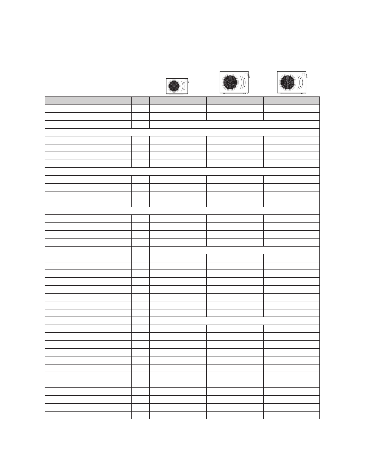
2.1 Performance data
UNIT Dura Pro 12 Dura Pro 17 Dura Pro 21
Max Pool volume* m
3
30 - 60 40 - 75 50-95
Advised Pool volume m
3
40 50 65
Operating air temperature °C -15 ~ 43
Air 27°C / Water 26°C / Humidity 80%
Heating Capacity kW 2,85 - 12 3,77 - 17 4,6 - 19,5
Btu 9690 - 40800 12818 - 57800 15640 - 66300
Consumed power kW 0,21 - 2,12 0,3 - 3,02 0,37 - 3,94
COP 13,57 - 5,66 12,57 - 5,63 12,43 - 4,95
Air 15°C / Water 26°C / Humidity 70%
Heating Capacity kW 2,25 - 9,7 2,92 - 12,4 3,84 - 15,4
Btu 7650 - 32980 9928 - 42160 13056 - 52360
Consumed power kW 0,32 - 2,08 0,44 - 2,86 0,6 - 3,81
COP 7,03 - 4,66 6,64 - 4,34 6,4 - 4,04
Air 10°C / Water 26°C / Humidity 64%
Heating Capacity kW 1,88 - 8 2,5 - 10,7 3,38 - 14,4
Btu 6329 - 27200 8500 - 36380 11492 - 48960
Consumed power kW 0,33 - 1,95 0,45 - 2,64 0,62 - 3,62
COP 5,7 - 4,1 5,56 - 4,05 5,45 - 3,98
Power supply 230V / 50Hz
Nominal Heating Capacity kW 7,1 9,7 11,5
Nominal power input kW 0,99 1,38 1,72
Max power input kW 2,5 3,2 4,88
Nominal Running current A 4,3 6 7,5
Current range A 0,9 - 9,2 1,3 - 13,1 1,6 - 17,1
Max Current A 13 13,96 21,17
Compressor quantity 1 1 1
Compressor type Rotary Rotary Rotary
Refrigerant R410A
Fan quantity 1 1 1
Fan power input W 100 120 120
Fan rotary speed RPM 600 - 800 600 - 750 600 - 900
Fan direction Horizontal Horizontal Horizontal
Noise dB(A) 42 44 45
Water connection mm 50 50 50
Nominal water ow m
3
/h 4,2 5,3 6,6
Water pressure drop (max) kPa 4,5 5 6
Unit net dimensions (L*W*H) mm 1003*396*767 1117*430*868 1117*430*868
Unit shipping dimensions (L*W*H) mm 1130*460*790 1210*510*880 1210*510*880
Net weight kg 59 77 82
Shipping weight kg 69 89 95
* Advised pool volume for an entirely insulated pool, with cover, free from wind and exposed to the sun
In case the pool volume is close to the maximum value, the inverter heatpump will nearly always run at full power
** Advised pool volume for efcient heating
Page 5
5
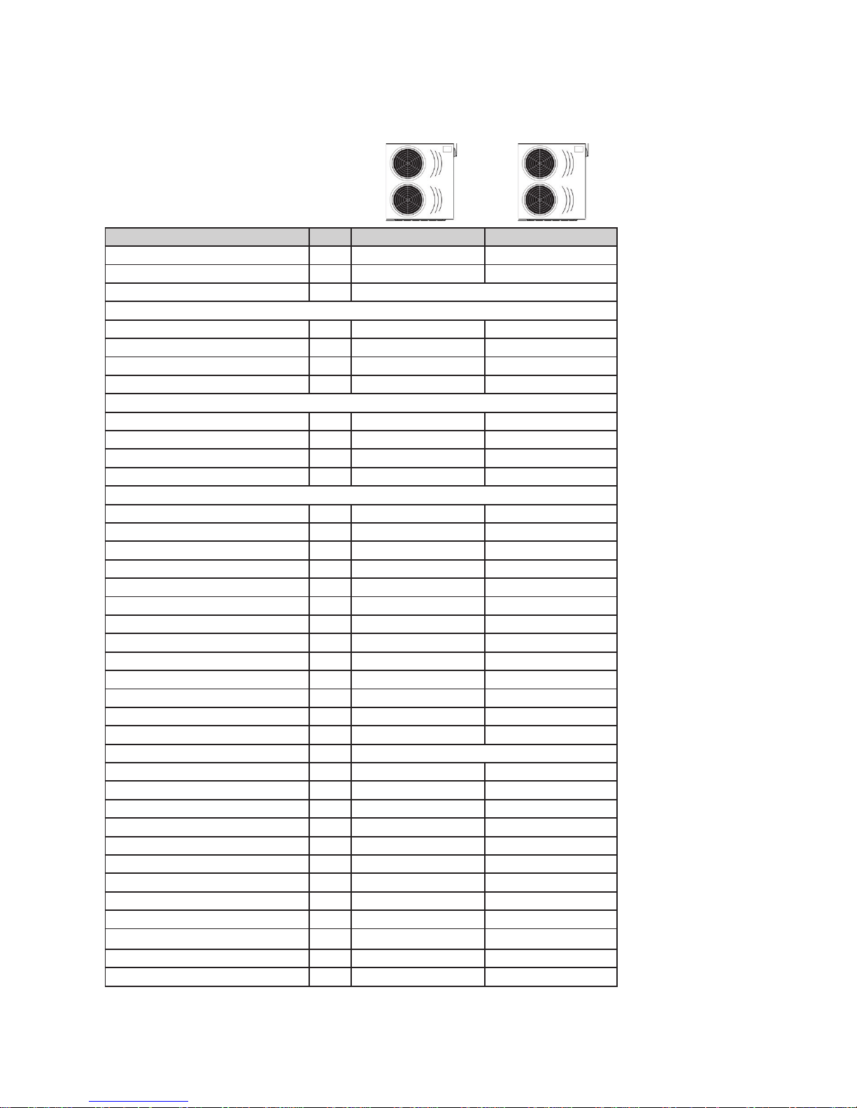
UNIT Dura Pro 25 Dura Pro 28T
Max Pool volume* m
3
65 - 120 90 - 169
Advised Pool volume m
3
75
Operating air temperature °C -15 ~ 43
Air 27°C / Water 26°C / Humidity 80%
Heating Capacity kW 5,7 - 24,2 6,7 - 28,3
Btu 19380 - 82280 22780 - 96220
Consumed power kW 0,46 - 4,8 0,54 - 5,57
COP 12,39 - 5,04 12,41 - 5,08
Air 15°C / Water 26°C / Humidity 70%
Heating Capacity kW 4,68 - 19,9 5,46 - 23,3
Btu 15912 - 67660 18564 - 79220
Consumed power kW 0,72 - 4,74 0,83 - 5,49
COP 6,5 - 4,2 6,58 - 4,24
Air 10°C / Water 26°C / Humidity 64%
Heating Capacity kW 4,2 - 17,8 4,9 - 20,8
Btu 14280 - 60520 16660 - 70720
Consumed power kW 0,75 - 4,4 0,87 - 5,1
COP 5,6 - 4,05 5,63 - 4,08
Power supply 230V / 50Hz 380-400V (3Phase)
Nominal Heating Capacity kW 14,3 16,6
Nominal power input kW 2,1 2,46
Max power input kW 5,52 6,72
Nominal Running current A 9,1 4,6
Current range A 2 - 20,9 1,13 - 9,29
Max Current A 24,09 11,2
Compressor quantity 1 1
Compressor type Rotary Rotary
Refrigerant R410A
Fan quantity 2 2
Fan power input W 200 200
Fan rotary speed RPM 400 - 800 400 - 800
Fan direction Horizontal Horizontal
Noise dB(A) 46 48
Water connection mm 50 50
Nominal water ow m
3
/h 8,6 10
Water pressure drop (max) kPa 11 15
Unit net dimensions (L*W*H) mm 1163*447*1275 1163*447*1275
Unit shipping dimensions (L*W*H) mm 1210*495*1300 1210*495*1300
Net weight kg 110 110
Shipping weight kg 125 125
* Advised pool volume for an entirely insulated pool, with cover, free from wind and exposed to the sun
In case the pool volume is close to the maximum value, the inverter heatpump will nearly always run at full power
** Advised pool volume for efcient heating
Page 6
6
A
Dura Pro 17 Dura Pro 21
400 470
L
H
W
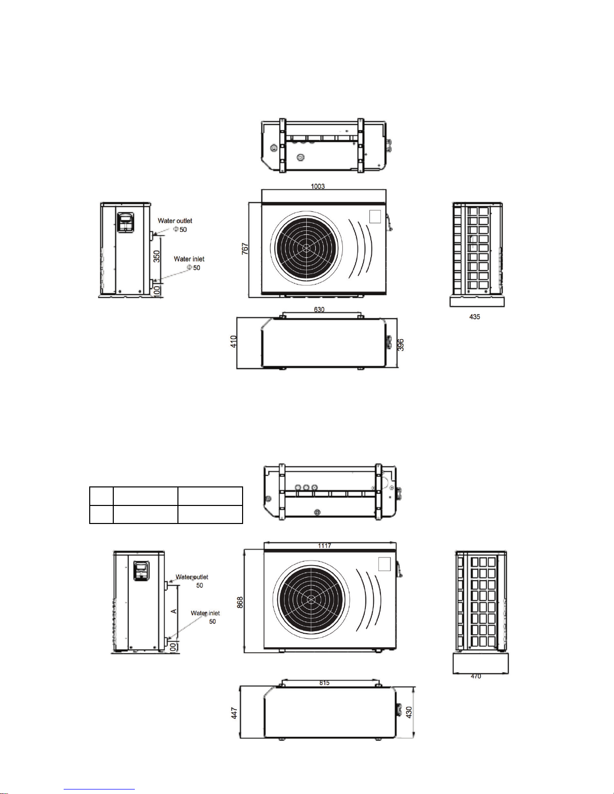
1003 mm
767 mm
410 mm
L
H
W
1117 mm
868 mm
447 mm
2.2 Dimensions
DURA Pro 12
DURA Pro 17 / 21
Page 7
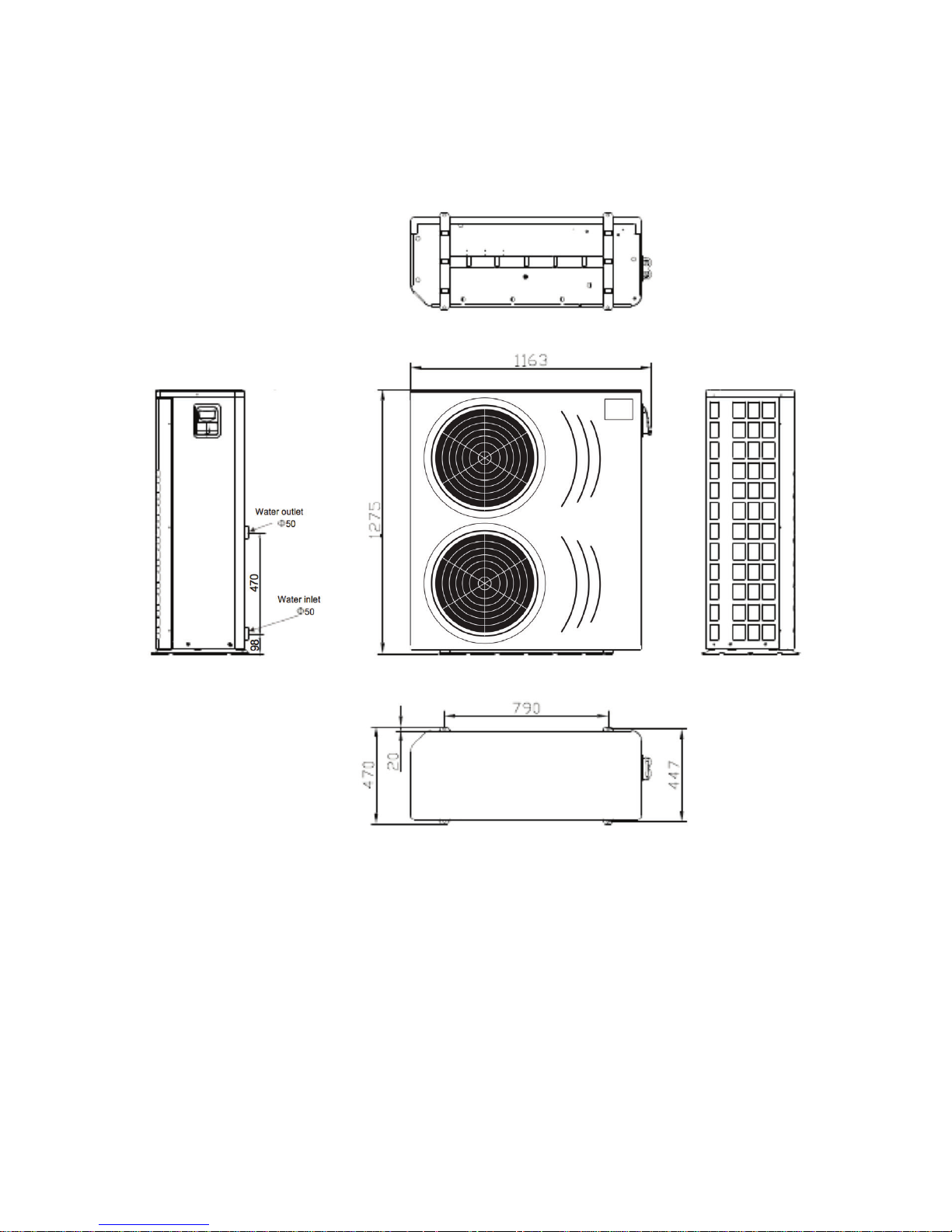
7
L
H
W
1163 mm
1275 mm
470 mm
DURA Pro 25 / 28T
Page 8
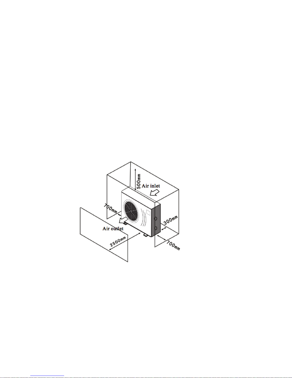
8
3. Installation and Connection
3.1 Heat Pump Location
The unit will perform well in any outdoor location provided that the following three factors are
presented:
1. Fresh Air - 2. Electricity - 3. Pool lter piping
The unit may be installed virtually anywhere outdoors. For indoor pools please consult the
supplier. Unlike a gas heater, it has no draft or pilot light problem in a windy area.
DO NOT place the unit in an enclosed area with a limited air volume, where the units
discharge air will be re-circulated.
DO NOT place the unit to shrubs which can block air inlet. These locations deny the unit of a
continuous source of fresh air which reduces its efciency and may prevent adequate heat
delivery.
3.2 How Close To Your Pool?
Normally, the pool heat pump is installed within 7.5 meters of the pool. The longer the distance
from the pool, the greater the heat loss from the piping. For the most part ,the piping is buried.
Therefore, the heat loss is minimal for runs of up to15 meters(15 meters to and from the pump =
30 meters total), unless the ground is wet or the water table is high. A very rough estimate of heat
loss per 30 meters is 0.6 kW-hour,(2000BTU) for every 5°C difference in temperature between the
pool water and the ground surrounding the pipe, which translates to about 3% to 5% increase in
run time.
Page 9
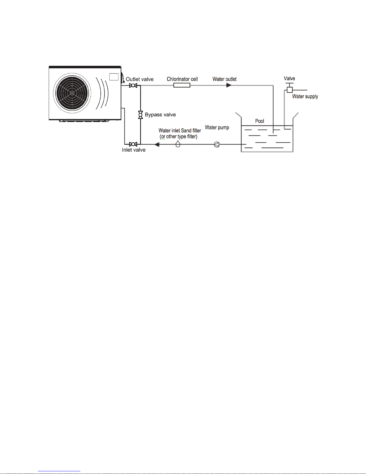
9
3.3 Installation illustration
Remarks:
The factory only provides the heat pump. Other parts, including a contingent by-pass are to be
provided by the user or installer.
Attention:
Please take the following steps when installing the heat pump:
1. Each addition of chemicals has to be performed through the conduits located AFTER the heat pump.
2. Install a by-pass for easy maintenance
3. Always place the heat pump on a solid base and use the supplied silent blocks in order to avoid
vibrations and noise.
4. Always keep the heat pump in upright position. If the unit has been tilted, you should wait for at least
24 hours before turning it on.
3.4 Installation of a check valve
When using automatic chlorine and pH dosage systems, it is of uttermost importance to protect
the heat pump from high concentrations of these chemicals that could corrode the heat exchanger
Therefore, such systems should add the chemicals in the conduits located DOWNSTREAM of the
heat pump and it is recommended to install a check-valve in order to prevent backow when there
is no water circulation.
Damage to the heat pump caused by disregarding any of these recommendations will invalidate
the warranty.
Page 10
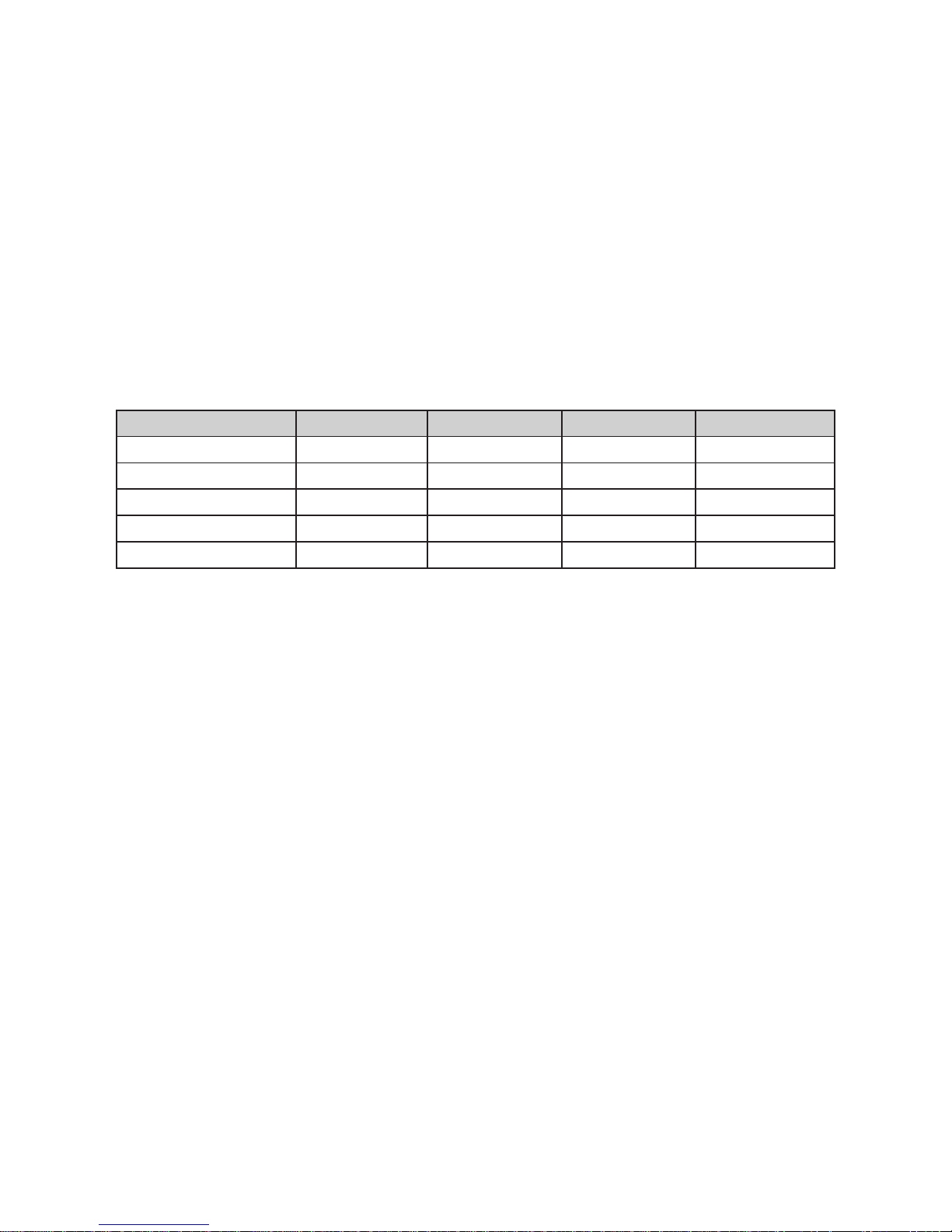
10
3.5 Electrical Wiring
Important - Although the heat pump is electrically isolated from the rest of the unit, this
only prevents the passage of electricity to or from the pool water. Grounding the unit is still
required to protect yourself from short circuits inside the unit. Make for adequate ground
connection.
Check if the electrical mains voltage corresponds with the operating voltage of the heat pump
prior to hooking up the unit.
It is recommended to use a separate fuse (C-curve) as well as adequate wiring (see table below).
Connect the electrical wires with the terminal block labelled ‘TO POWER SUPPLY’.
Next to this connection, there is a second terminal block labelled ‘TO PUMP’, to which the lter
pump (max. 5A/240V) or an electrical relay for a ltration pump can be connected. This connection makes it possible to control lter pump operation with the heat pump.
3.6 Initial startup of the Unit
NOTE- In order for the unit to heat the pool or spa, the lter pump must be running to
circulate water through the heat exchanger.
Start up Procedure - After installation is completed, you should follow these steps:
1. Turn on your lter pump. Check for water leaks and verify ow to and from the pool.
2. Turn on the electrical power supply to the heatpump, then press the key ON/OFF of wire con-
troller, It should start in several seconds.
3. After running a few minutes make sure the air leaving the fan opening of the unit is cooler
(between 5-10°C)
4. With the unit operating turn the lter pump off. The unit should also turn off automatically,
5. Allow the unit and pool pump to run 24 hours per day until desired pool water temperature is
reached. When the desired pool water temperature reaches the setting, the unit just shuts off.
The unit will now automatically restart (as long as your lter pump is running) when the pool temperature drops more than 2°C below set temperature.
Time Delay- The unit is equipped with a 3 minute built-in solid state restart delay included to
protect control circuit components and to eliminate restart cycling and contactor chatter.
This time delay will automatically restart the unit approximately 3 minutes after each control
circuit interruption. Even a brief power interruption will activate the solid state 3 minute
restart delay and prevent the unit from starting until the 5 minute countdown is completed.
Power interruptions during the delay period will have no effect on the 3 minute countdown.
Model Voltage (V) Fuse (C-curve) Max current (A) Cable section*
DURA Pro 12 220-240V 20 13 2,5 mm
2
DURA Pro 17 220-240V 20 13,96 2,5 mm
2
DURA Pro 21 220-240V 32 21,17 4 mm
2
DURA Pro 25 220-240V 32 24,09 4 mm
2
DURA Pro 28T 3x 400V 32 (3 phase) 11,2 2,5 mm
2
* For a maximum cable length of 50m
Page 11

11
3.7 Condensation
Since the Heat pump cools down the air about 5°C, water may condense on the ns of the evaporator. If the relative humidity is very high, this could be as much as several liters an hour. The
water will run down the ns into the base pan and drain out through the barbed plastic condensation drain tting on the side of the base pan.
This tting is designed to accept 20mm clear vinyl tubing which can be pushed on by hand
and run to a suitable drain. It is easy to mistake the condensation for a water leak inside the
unit.
TIP:
A quick way to verify that the water is condensation is to shut off the unit and keep the
pool pump running. If the water stops running out of the base pan, it is condensation. AN
EVEN QUICKER WAY IS TO TEST THE DRAIN WATER FOR CHLORINE - if there is no chlorine
present, then it’s condensation.
Page 12
12
4. Operation and Use
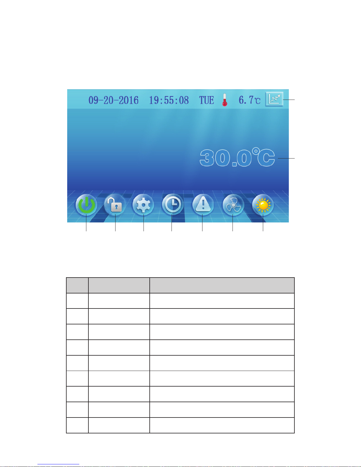
4.1 Display interface introduction
1. Main interface
1
2. Button description
2 3 4 5 6 7
9
8
NO. Name button function
1 ON/OFF Start/Stop the unit
2 Lock screen Locks the screen
3 Parameters Acces to parameters
4 Clock settings
- Set the date & time
- Activate timers
5 Error codes View error code history
6 Silent settings
- Press to activate silent function
- Set timing Low speed function
7 Mode Mode switch interface
8 Statistics View temperature and power curve
9 Water temperature Mode settings and target temp setting interface
Page 13
13
4.2 Button functions
1. ON/OFF
With the ON/OFF button, the heatpump is turned ON or OFF (stand-by status)
2. LOCK SCREEN
Press this button to lock the screen
To unlock: press the lock button and enter the code “22”
3. PARAMETERS
N/A
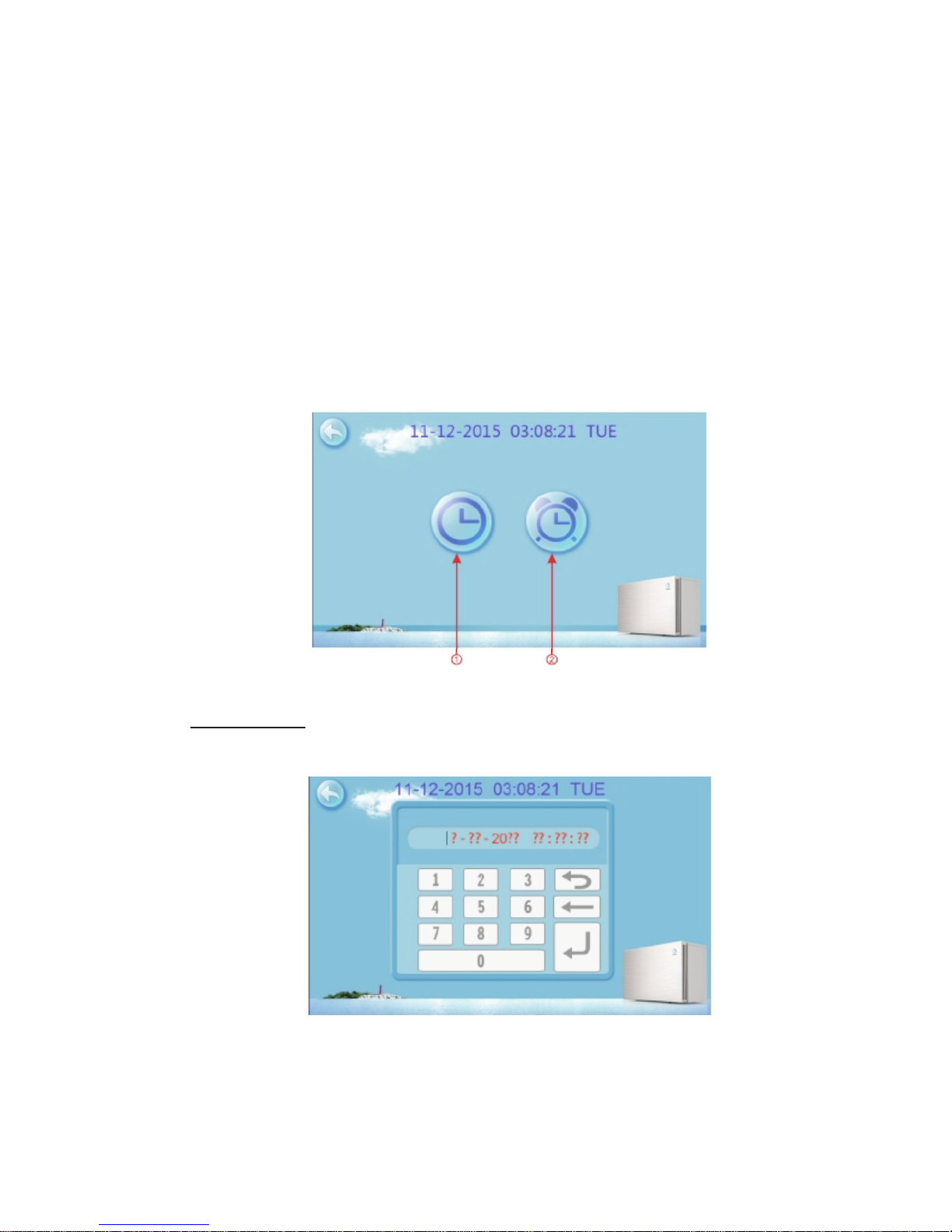
4. CLOCK SETTINGS
In the main interface, tap on the clock Settings button 3, interface displays as follows:
Setting the time
tap on the Time Settings button (1), then the following menu pops up:
Tap the value to set time directly, the tap the Enter button to save the Settings.
For example: setup time: the 02-25-2016 15:00:00, input 15 00 00 02 25 16
Note:
if the input format is not correct, the setting can not be saved by tapping Enter.
Page 14
14
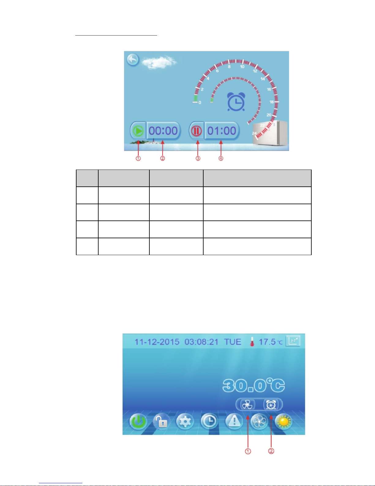
Setting/activating the Timers
Tap the TIMER set button (2), to enter the timer menu
For example above: without action, 00:00 o ‘clock and 01:00 o ‘clock
will be the on and off time of timing settings.
5. ERROR CODES
See section 4.3
6. SILENT SETTINGS
In the main screen, tap the silent settings button
A pop-up appears with 2 icons:
TIMER START
Tap this button to activate/deactivate
the START timer
1
Activated: Green
Not activated: Grey
TIMER END
Tap this button to activate/deactivate
the END timer
3
Activated: Red
Not activated: Grey
Start time Set Start time 2
End time Set End time 4
Name Button function NO Button color
Page 15
15
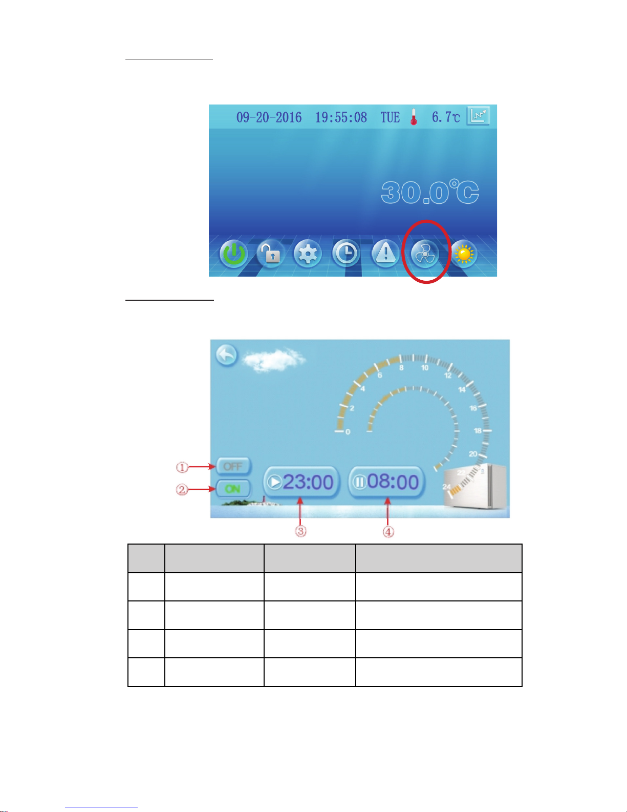
Direct silent mode
Tap the Direct silent button (1), the unit will enter silent mode directly.
The displays shows a fan icon with 3 blades to indicate that the silent mode is active
Tap the silent button again, to exit the silent mode.
Timed silent mode
Tap the Timed silent button (2)
The displays shows a menu with timer settings to activate/deactivate the silent mode
For example above, Tap “ON” to use the Timed silent mode
the unit will start the silent mode at 23:00h and end at 08:00h
Note: If the unit is running in silent mode, and the OFF button (1) is tapped, then the
unit will exit silent mode immediately
Timer SILENT OFF
Tap to activate/deactivate the
END timer
1
Activated: Red
Not activated: Grey
Start time Set start time 3
Timer SILENT ON
Tap to activate/deactivate the
START timer
2
Activated: Green
Not activated: Grey
End time Set end time 4
Name Button function NO Button color
Page 16
16
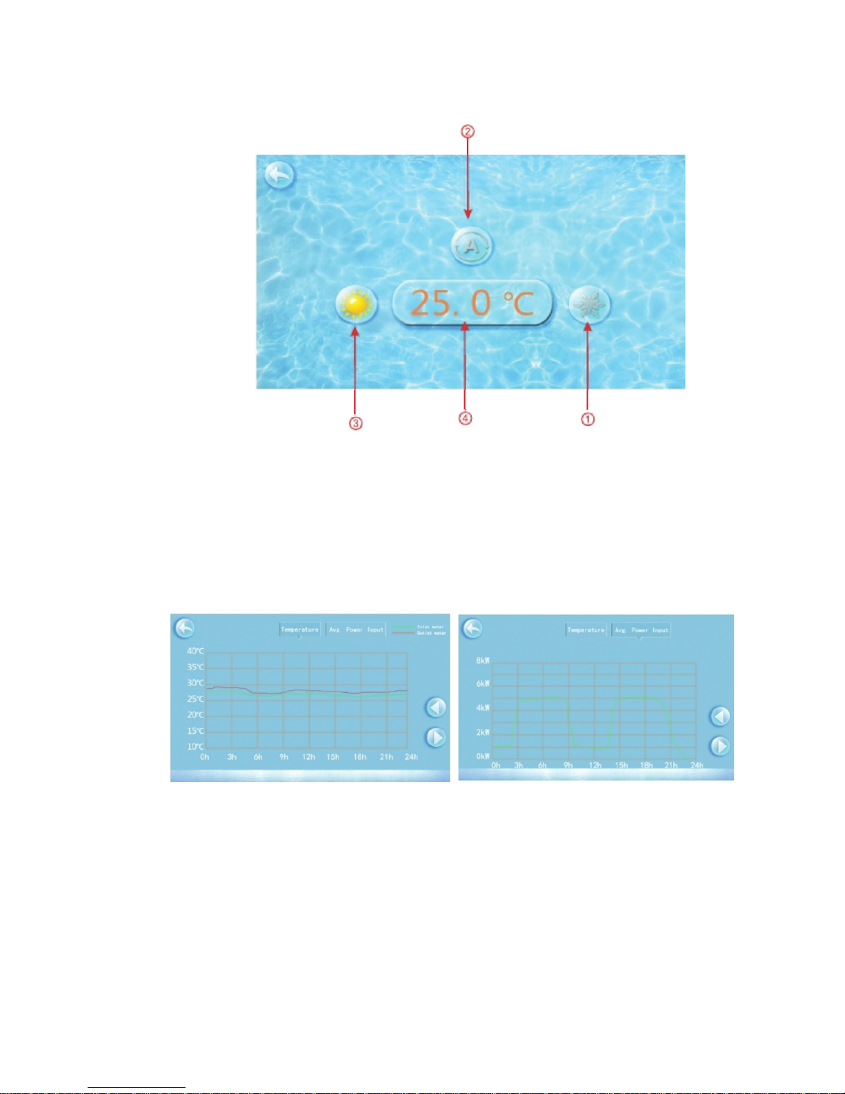
7. MODE
In the main screen, tap the Mode button.
A new menu will pop up:
1) Cooling mode
2) Automatic heating/cooling mode
3) Heating mode
4) Set desired swimming pool temperature
8. STATISTICS
In the main screen, tap the Statistics button.
A new menu will pop up.
The temperature curve automatically updates every hour, and the curve record can be
stored for 60 days
9. WATER TEMPERATURE
Set the desired swimming pool water temperature
Page 17
17
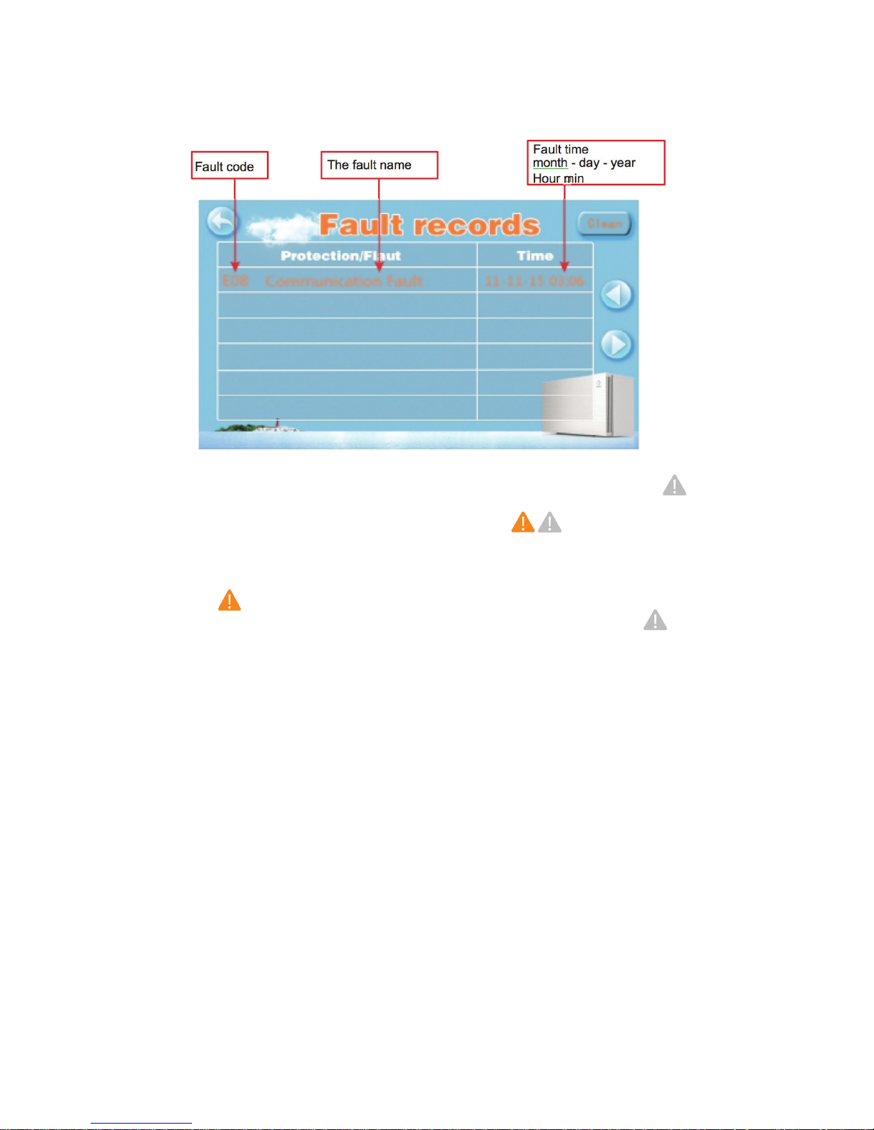
If there are no error codes present, the main display will show a grey triangle logo:
When an error occurs, the error icon will ash orange/grey:
the system will record the time, code and name of the error.
When an error occurs, and you don’t check the Error code history menu, the main interface will
display a static “ “ icon after a while.
If you do check Error code history menu, the main interface will display a static “ “ icon.
The Error code history meny shows all the error codes in reverse order, with the most recent code
on top. If you tap the “Clean” key, you can erase all the codes.
4.3 Error codes
In the main screen, tap the Error codes button.
A new menu will pop up:
Page 18
18
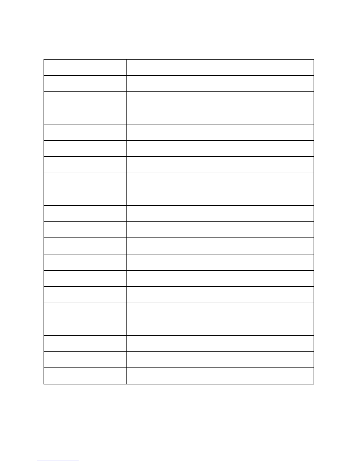
4.4 Error code list
E07
P02
Fault
display
non
P081
E29
P05
non
P082
E02
E19
P04
non
E051
E01
E06
P07
P01
E08
E03
Check the pipe water ow and whether
the water system is jammed or not
Check or change the
temp. Sensor
Elimination methods
Check or change the
temp. Sensor
Check or change the
temp. Sensor
Check whether the system of
the compressor is running normally
Check the pressure
switch and cold circuit
Check or change the
temp. Sensor
Check whether the system of
the compressor is running normally
Check the pressure
switch and cold circuit
Check the pipe water ow and whether
the water system is jammed or not
Check or change the
temp. Sensor
Check or change the
temp. Sensor
Check the wire connection between
remote wire controller and main board
Check the pipe water
ow and water pump
System anti freezing
protection
Outlet temp. Sensor failure
Protect/fault
Low temperature protection
Exhaust temp. sensor failure
The secondary
anti-freezing Protection
Ambient temp. sensor failure
Normal boot
Exhaust Temp. Of system
is too high
Low pressure protection
The primary anti-freezing
protection
Coil temp. Sensor failure
Standby
Compressor too much
electricity protection
High pressure protection
Water-inlet and outlet temp
Suction temp. sensor failure
Inlet temp. Sensor failure
Communication failure
Flow failures
Water ow is not enough
The temp. Sensor is broken
or short circuit
Reason
The environment temp. is low
The temp. Sensor is broken
or short circuit
The ambient temp. Is low
The temp. Sensor is broken
or short circuit
The compressor is overload
Low pressure1 protection
The ambient temp. Is low
The temp. Sensor is broken
or short circuit
The compressor is overload
The high-presesure switch is
broken
Water ow is not enough
and low differential pressure
The temp. Sensor is broken
or short circuit
The temp. Sensor is broken
or short circuit
Communication failure between
wire controller and main board
No water/little water in
water system
Page 19
19
Fault
display
F08
F17
F04
F12
F22
F02
F10
F19
F06
F14
F24
F01
F09
F18
F05
F13
F23
F03
F11
F20
F07
F16
F15
F25
Elimination methods
Check the input voltage measurement
Check and measure the voltage
adjustment
Check the measuring voltage check
frequency conversion board hardware
Check the communication connection
Check and adjust the current
measurement
Check the
communication connection
Check the input voltage measurement
Inspect and replace the sensor
Check and adjust the current
measurement
Check the communication connection
Check and adjust the current
measurement
Recovery after the 150s
Check the input voltage measurement
Check and adjust the current
measurement
Check whether current return wires
connected motor,
Check the communication connection
The compressor over-current
protection
Recovery after the 150s
Check and adjust the current
measurement
Check and adjust the current
measurement
Check the input voltage measurement
Check and adjust the current
measurement
Check whether the chip is damaged
Replace the chip
Protection/fault
Dc voltage is not enough
The input voltage lost phase
Compressor start-up failure
DSP and PFC connect fault
Transducer overheating
alarm
Frequency conversion board
ofine
Input voltage is large
Radiator temperature sensor
fault
IPM Input current is large
protection
DSP and MCU connect fault
Input current too large alarm
MOP drive alarm
Input voltage is not enough
IPM sampling electricity
Dc fan fault
DSO and SPPB connect fault
Compressor electricity large
protection
IPM modular protection
Voltage sampling fault
Transducer overheating
protection
Dc voltage is large
Weak magnetic eld
protection
IPM overheating protection
EEPROM error alarm
Reason
DC bus voltage<Dc bus over-voltage
protection value
The input voltage lost phase
Lack of phase, step or drive hardware
damage
DSP and PFC connect fault
Transducer temperature is too
high
Frequency conversion board and main
board communication failure
The input voltage is too high, more than
outage protection current RMS
Sensor is short circuit or open
circuit
IPM Input current is large
DSP and MCU connect fault
Input current is too large
MOP drive alarm
The input voltage is low, causing the
input current is high
IPM sampling electricity is fault
Motor current feedback open circuit or
short circuit
DSO and SPPB connect fault
Compressor electricity is large
IPM modular protection
The input voltage sampling fault
The transducer is overheat
DC bus voltage>Dc bus over-voltage
protection value
Compressor magnetic force is not
enough
The IPM module is overheat
MCU error
Page 20
20
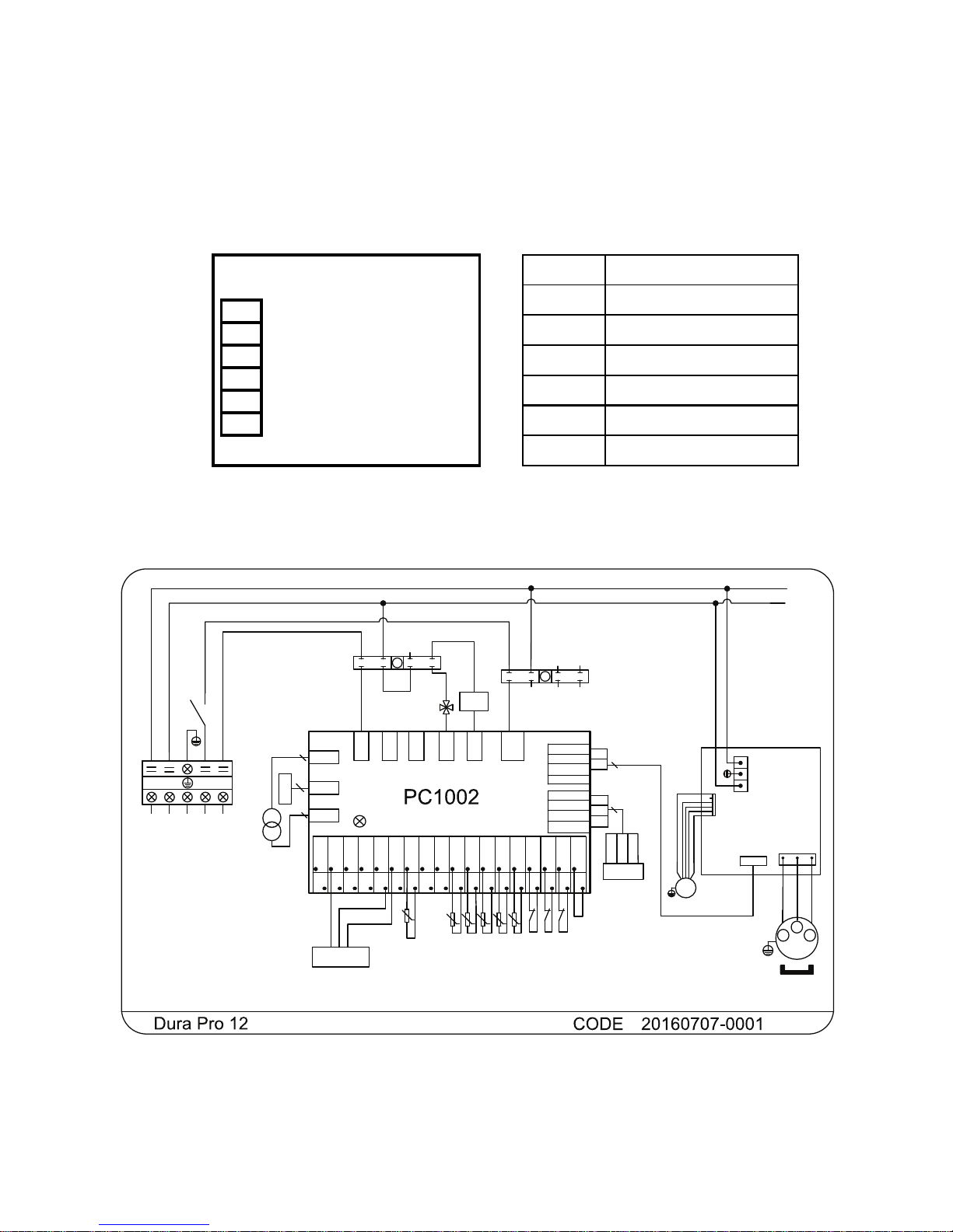
5. Wiring diagrams
5.1 Wire control interface diagram and denition
5.2 Controller interface diagram and denition
Function Terminal
Not used R
R
485B B
B
12V power + V
V
485A A
A
Not used T
T
GND (power -) G
G
CN7
CN9
J2
R485B1
GND
L
RLY1
OUT2
OUT3
OUT4
OUT5
R485A1
+12V
CN2
+12V
+5V
0~10V-OUT
PWM-OUT
AI12
AI/DI11
AI/DI10
AI/DI09
PWM-IN
AI/DI08
AI/DI07
AI/DI06
AI/DI05
AI/DI04
AI/DI03
AI/DI02
AI/DI01
0~5V-IN
R485A2
+12V
CN8
R485B2
GND
GND
GND
GND
GND
GND
GND
GND
GND
GND
GND
GND
GND
GND
GND
GND
GND
GND
GND
L
N
A BGND12V
YEL
RED
BLK
COMP
U
V
W
U
W
V
L
N
LN
1
2
L
N
N
EEV
5
4V
TC
24V
2
2
FS
FS
FS
LP
LP
HP
HP
LPHP
t
5K
SUT
SUT
SUT
t
5K
IT
IT
IT
t
5K
OT
OT
OT
CT
CT
t
5K
CT
AT
AT
t
5K
AT
N
N4V
1
3
245678
01
K2
P
N
N
NN
N
FM
ET
ET
YEL
BLK
WHT
RED
4
Controller
YEL 485B-
BLK GND
RED 12V
WHT 485A+
DCFAN1
220-240V~/50Hz
L
:
K2
N
N
N
N
N
1
3
245678
02
L
L
K2
L
N
L
L
L
RED
BLU
TO POWER
SUPPLY
TO
PUMP
Pressure sensor
(SUT)
RED
BLK
WHT
t
50K
ET
AT:Ambient temperature
COMP:Compressor
CT:Coil temperature
FM:Fan motor
IT:Inlet water temperature
LP:Low pressure protection
OT:Outlet water temperature
FS:Flow switch
HP:High pressure protection
SUT:Suction temperature
EEV:Electronic expand valve
ET:Exhaust temperature
TC:Transformer
4V:4 way valve
K2:Relay of pump
RED
BLK WHT
AC-N1
3
4
4
Remote
ON/OFF
Page 21
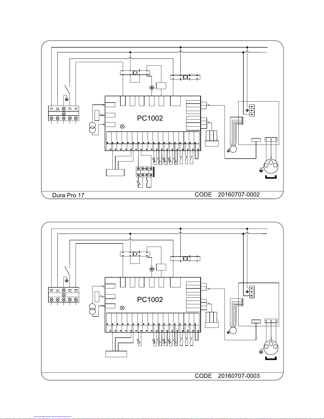
21
CN7
CN9
J2
485B1
GND
3
RLY1
OUT2
OUT3
AC-N1
OUT4
OUT5
485A1
12V
CN2
+12V
+5V
0~10V-OUT
PWM-OUT
AI12
AI/DI11
AI/DI10
AI/DI09
PWM-IN
AI/DI08
AI/DI07
AI/DI06
AI/DI05
AI/DI04
AI/DI03
AI/DI02
AI/DI01
0~5V-IN
485A2
12V
CN8
485B2
GND
GND
GND
GND
GND
GND
GND
GND
GND
GND
GND
GND
GND
GND
GND
GND
GND
GND
GND
L
N
A BGND12V
YEL
RED
BLK
4
COMP
U
V
W
RED
BLK
WHT
U
W
V
L
N
LN
1
2
L
N
N
EEV
5
4V
TC
24V
2
2
FS
FS
FS
LP
LP
HP
HP
LPHP
t
5K
SUT
SUT
SUT
t
5K
IT
IT
IT
t
5K
OT
OT
OT
CT
CT
t
5K
CT
AT
AT
t
5K
AT
N
N4V
1
3
245678
01
K2
P
N
N
NN
N
FM
ET
ET
YEL
BLK
WHT
RED
4
Controller
YEL 485B-
BLK GND
RED 12V
WHT 485A+
DCFAN1
220-240V~/50Hz
L
:
K2
N
N
N
N
N
1
3
245678
02
L
L
K2
L
N
L
L
L
RED
BLU
TO POWER
SUPPLY
TO
PUMP
Pressure sensor
(SUT)
RED
BLK
WHT
AT:Ambient temperature
COMP:Compressor
CT:Coil temperature
FM:Fan motor
IT:Inlet water temperature
LP:Low pressure protection
OT:Outlet water temperature
FS:Flow switch
HP:High pressure protection
SUT:Suction temperature
EEV:Electronic expand valve
ET:Exhaust temperature
TC:Transformer
4V:4 way valve
K2:Relay of pump
t
50K
EP
ET
EP
EP
1
24
1
4
EP:Exhaust protection
4
CN7
CN9
J2
485B1
GND
3
RLY1
OUT2
OUT3
AC-N1
OUT4
OUT5
485A1
12V
CN2
+12V
+5V
0~10V-OUT
PWM-OUT
AI12
AI/DI11
AI/DI10
AI/DI09
PWM-IN
AI/DI08
AI/DI07
AI/DI06
AI/DI05
AI/DI04
AI/DI03
AI/DI02
AI/DI01
0~5V-IN
485A2
12V
CN8
485B2
GND
GND
GND
GND
GND
GND
GND
GND
GND
GND
GND
GND
GND
GND
GND
GND
GND
GND
GND
L
N
A BGND12V
YEL
RED
BLK
4
COMP
U
V
W
U
W
V
L
N
LN
1
2
L
N
N
EEV
5
4V
TC
24V
2
2
FS
FS
FS
LP
LP
HP
HP
LPHP
t
5K
SUT
SUT
SUT
t
5K
IT
IT
IT
t
5K
OT
OT
OT
CT
CT
t
5K
CT
AT
AT
t
5K
AT
N
N4V
1
3
245678
01
K2
P
N
N
NN
N
FM
ET
ET
YEL
BLK
WHT
RED
4
Controller
YEL 485B-
BLK GND
RED 12V
WHT 485A+
CON1
220-240V~/50Hz
L
:
K2
N
N
N
N
N
1
3
245678
02
L
L
K2
L
N
L
L
L
RED
BLU
TO POWER
SUPPLY
TO
PUMP
RED
BLK
WHT
t
50K
ET
4
Remote
ON/OFF
Pressure sensor
(SUT)
AT:Ambient temperature
COMP:Compressor
CT:Coil temperature
FM:Fan motor
IT:Inlet water temperature
LP:Low pressure protection
OT:Outlet water temperature
FS:Flow switch
HP:High pressure protection
SUT:Suction temperature
EEV:Electronic expand valve
ET:Exhaust temperature
TC:Transformer
4V:4 way valve
K2:Relay of pump
Dura Pro 21
Page 22
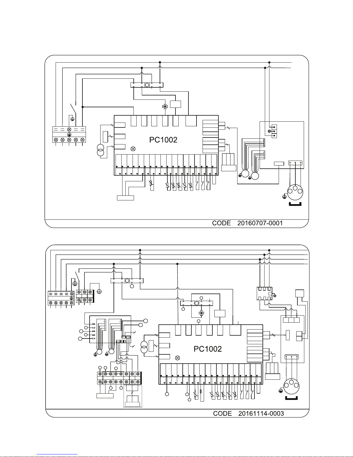
22
CN7
CN9
J2
R485B1
GND
3
RLY1
OUT2
OUT3
OUT4
OUT5
R485A1
+12V
CN2
+12V
+5V
0~10V-OUT
PWM-OUT
AI12
AI/DI11
AI/DI10
AI/DI09
PWM-IN
AI/DI08
AI/DI07
AI/DI06
AI/DI05
AI/DI04
AI/DI03
AI/DI02
AI/DI01
0~5V-IN
R485A2
+12V
CN8
R485B2
GND
GND
GND
GND
GND
GND
GND
GND
GND
GND
GND
GND
GND
GND
GND
GND
GND
GND
GND
L
N
A BGND12V
YEL
RED
BLK
COMP
U
V
W
U
W
V
L
N
LN
1
2
L
N
N
EEV
5
4V
TC
24V
2
2
FS
FS
FS
LP
LP
HP
HP
LPHP
t
5K
SUT
SUT
SUT
t
5K
IT
IT
IT
t
5K
OT
OT
OT
CT
CT
t
5K
CT
AT
AT
t
5K
AT
N
N4V
1
3
245678
01
K2
P
N
N
NN
N
FM1
ET
ET
YEL
BLK
WHT
RED
4
Controller
CON1
220-240V~/50Hz
L
:
K2
L
LL
N
K2
L
N
L
RED
BLU
TO POWER
SUPPLY
TO
PUMP
Negative pressure
sensor
RED
BLK
WHT
t
50K
ET
AT:Ambient temperature
COMP:Compressor
CT:Coil temperature
FM:Fan motor
IT:Inlet water temperature
LP:Low pressure protection
OT:Outlet water temperature
FS:Flow switch
HP:High pressure protection
SUT:Suction temperature
EEV:Electronic expand valve
ET:Exhaust temperature
TC:Transformer
4V:4 way valve
K2:Relay of pump
AC-N1
4
4
N
N
L
FM2
CON2
Remote
ON/OFF
YEL 485B-
BLK GND
RED 12V
WHT 485A+
Dura Pro 25
CN9
485B1
GND
3
RLY1
OUT2
OUT3
AC-N1
OUT4
OUT5
485A1
12V
CN2
+12V
+5V
0~10V-OUT
PWM-OUT
AI12
AI/DI11
AI/DI10
AI/DI09
PWM-IN
AI/DI08
AI/DI07
AI/DI06
AI/DI05
AI/DI04
AI/DI03
AI/DI02
AI/DI01
0~5V-IN
485A2
12V
CN8
485B2
GND
GND
GND
GND
GND
GND
GND
GND
GND
GND
GND
GND
GND
GND
GND
GND
GND
GND
GND
R
FS
FS
FS
LP
LP
HP
HP
LPHP
t
5K
IT
IT
IT
t
5K
OT
OT
OT
CT
CT
t
5K
CT
AT
AT
t
5K
AT
N
4V
1
3
24
5
6
7
8
01
R
ET
YEL
BLK
WHT
RED
:
R
t
50K
4
ET
ET
SUT
SUT
SUT
t
5K
EEV
5
RST
N
RED
BLK
WHT
BLU
N
N
N
N
R
R
Remote
ON/OFF
A BGND12V
COMP
U
V
W
U
W
V
2
1
B
A
R
A
B
S
T
R
S
T
S
RST
YEL
RED
BLK
4
K2
N
N
N
N
N
K2
R
R
P
RS
T
N
TO PUMP
Controller
YEL 485B-
RED 12V
WHT 485A+
ACN
CN1
TP1TP2
L3
N1
L5
ACL
CN4
FM1
ZL10
4V
2
4
N
FM2
PRS2
(WHT)
PRS1
(BLK)
NET2
(RED)
Y/G
BLU
BRN
BRN
N
K2
1
3
24
5
6
7
8
02
4V
4V
4V
N
N
N
4V
N
N
1
W
D
Pressure sensor
(SUT)
D
2
B
Detector
3
Y/G
BLU
BRN
Y/G
BLU
BRN
4
1
1
Y/G Y/G BLU BRN
2
BLU
4
BLK GND
6.8K
TO POWER SUPPLY
380-415V/3N~/50Hz
N4
N
CN
CN4
CN3
R
4V
CN7
J2
TC
24V
2
2
AT:Ambient temperature
COMP:Compressor
CT:Coil temperature
FM:Fan motor
IT:Inlet water temperature
LP:Low pressure protection
OT:Outlet water temperature
FS:Flow switch
HP:High pressure protection
SUT:Suction temperature
EEV:Electronic expand valve
ET:Exhaust temperature
TC:Transformer
4V:4 way valve
K2:Relay of pump
Dura Pro 28T
Page 23

23
6. Maintenance and Inspection
• Check the water inlet and drainage often. The water and air inow into the system should be
sufcient so that its performance and reliability does not get compromised. You should clean the
pool lter regularly to avoid damage to the unit caused by clogging of the lter.
• The area around the unit should be spacious and well ventilated. Clean the sides of the heat
pump regularly to maintain good heat exchange and to save energy.
• Check if all processes in the unit are operational and pay special attention to the operation pressure of the refrigerant system.
• Check the power supply and cable connections regularly. Should the unit begin to function
abnormally or should you notice a smell from an electrical component, arrange for timely repair or
replacement.
• Winterizing : make sure to purge all the water from the heat pump and other systems in order to
prevent frost damage.
• You should also purge the water if the unit will not work for an extended period of time. You
should check all parts of the unit thoroughly and completely ll the system with water before turning it on again afterwards.
Page 24

24
7. Appendix
7.1 Caution & Warning
1. The unit can only be repaired by qualied installer center personnel or an authorised
dealer.
2. This appliance is not intended for use by persons (including children) with reduced
physical sensory or mental capabilities, or lack of experience and knowledge, unless
they have been given supervision or instruction concerning use of the appliance by a
person responsible for their safety. (for Europe market)
Children should be supervised to ensure that they do not play with the appliance.
3. Please make sure that the unit and power connection have good earthing, otherwise
may cause electrical shock.
4. If the supply cord is damaged, it must be replaced by the manufacturer or our service
agent or similarly qualied person in order to avoid a hazard.
5. Directive 2002/96/EC (WEEE):
The symbol depicting a crossed-out waste bin that is underneath the appliance indi cates that this product, at the end of its useful life, must be handled separately from
domestic waste, must be taken to a recycling center for electric and electronic devices
or handed back to the dealer when purchasing an equivalent appliance.
6. Directive 2002/95/EC (RoHs): This product is compliant with directive 2002/95/EC
(RoHs) concerning restrictions for the use of harmful substances in electric and elec tronic devices.
7. The unit CANNOT be installed near the ammable gas. Once there is any leakage of
the gas, re can be occur.
8. Make sure that there is a circuit breaker for the unit, lack of a circuit breaker can lead to
electrical shock or re.
9. The heat pump is equipped with an over-load protection system. It does not allow for
the unit to start for at least 3 minutes from a previous stoppage.
10. Installation must be performed in accordance with the NEC/CEC by authorized person
only. (for North America market)
11. USE SUPPLY WIRES SUITABLE FOR 75°C .
12. Caution: Single wall heat exchanger, not suitable for potable water connection.
Page 25

25
7.2 Warranty
EXTENDED WARRANTY
Thank you for purchasing our heat pump.
We warrant all parts to be free from manufacturing defects in materials and workmanship for a
period of THREE years from the date of retail purchase.
LIMITED WARRANTY
This warranty is limited to the rst retail purchaser, is not transferable, and does not apply to
products that have been moved from their original installation sites. The liability of the Manufacturer shall not exceed the repair or replacement of defective parts and does not include any costs
for labour to remove and reinstall the defective part, transportation to or from the factory, and any
other materials required to make the repair. This warranty does not cover failures or malfunctions
resulting from the following:
1. Failure to properly install, operate or maintain the product in accordance with our published
“Installation & Instruction Manual” provided with the product.
2. The workmanship of any installer of the product.
3. Not maintaining a proper chemical balance in your pool [pH level between 7,0 and 7,8.
Total Alkalinity (TA) between 80 to 150 ppm. Free Chlorine between 0,5 – 1,2mg/l.
Total Dissolved Solids (TDS) less than 1200 ppm. Salt maximum 8g/l]
4. Abuse, alteration, accident, re, ood, lightning, rodents, insects, negligence or acts of Gods.
5. Scaling, freezing or other conditions causing inadequate water circulation.
6. Operating the product at water ow rates outside the published minimum and maximum
specications.
7. Use of non-factory authorized parts or accessories in conjunction with the product.
8. Chemical contamination of combustion air or improper use of sanitizing chemicals, such as
introducing sanitizing chemicals upstream of the heater and cleaner hose or through the
skimmer.
9. Overheating, incorrect wire runs, improper electrical supply, collateral damage caused by
failure of O-rings, DE grids or cartridge elements, or damage caused by running the pump with
insufcient quantities of water.
LIMITATION OF LIABILITY
This is the only warranty given by Manufacturer. No one is authorized to make any other warranties on our behalf.
THIS WARRANTY IS IN LIEU OF ALL OTHER WARRANTIES, EXPRESSED OR IMPLIED,
INCLUDING BUT NOT LIMITED TO ANY IMPLIED WARRANTY OF FITNESS FOR A PARTICULAR PURPOSE AND MERCHANTABILITY. WE EXPRESSLY DISCLAIM AND EXCLUDE ANY
LIABILITY FOR CONSEQUENTIAL, INCIDENTAL, INDIRECT OR PUNITIVE DAMAGES FOR
BREACH OF ANY EXPRESSED OR IMPLIED WARRANTY.
This warranty gives you specic legal rights, which may vary, by country.
WARRANTY CLAIMS
For prompt warranty consideration, contact your dealer and provide the following information:
proof of purchase, model number, serial number and date of installation. The installer will contact
the factory for instructions regarding the claim and to determine the location of the nearest service
center.
All returned parts must have a Return Material Authorization number to be evaluated under the
terms of this warranty.
Page 26

26
Page 27
Contact details
Propulsion Systems bvba
Dooren 72
1785 Merchtem, Belgium
Tel +32 2 461 02 53
Fax +32 2 706 59 60
www.propulsionsystems.be
[email protected]
We reserve the rights to change all or part of the contents of this document without prior notice
heat pumps
 Loading...