

Page 1
HANDHELD COMPUTER
DA05 WinCE
Quick Start Guide
Page 2

Copyright © 2007
All rights reserved. No part of this publication may be reproduced, transmitted,
transcribed, stored in a retrieval system, or translated into any language, or computer
language, in any form, or by any means, electronic, mechanical, magnetic, optical,
chemical, or other, without the prior written permission of the manufacturer.
The manufacture reserves the right to revise this publication and to make changes
from time to time in the contents hereof without obligation to notify any person of
such revision or changes.
The manufacturer makes no representations or warranties, either expressed or
implied, with respect to the contents hereof and sp ecifically disclaims any warranties
as to merchantability or fitness for any particular purpose. Any of the manufacturer's
software described in this manual is sold or licensed "as is". Should the programs
prove defective following their purchase, the buyer (and not the manufacturer, its
distributor, or its dealer), assumes the entire cost of all necessary servicing, repair
and any incidental or consequential damages resulting from any defect in the
software.
Trademark Acknowledgments
IBM, PC are registered trademarks of International Business Machines Corp.
Page 3

Microsoft, Windows CE, Pocket PC, and Windows Mobile are registered trademarks
of Microsoft Corp.
Intel, Bulverde are the registered trademarks of Intel Corp.
All product and company names are trademarks or registered trademarks of their
respective holders.
Page 4

EMC and Safety Notice
Federal Communications Commission Radio Frequency Interference Statement
This equipment generates, uses, and can radiate radio frequency energy and if not
installed and used in accordance with the instructions, may cause interference to radio
communications. This equipment has been tested and found to comply with the limits
for a class B digital device, pursuant to part 15 of the FCC Rules. These limits are
designed to provide reasonable protection against harmful interference in a residential
installation.
This equipment generates, uses and can radiate radio frequency energy and, if not
installed and used in accordance with the instructions, may cause harmful interference
to radio communications. However, there is no guarantee that interference will not
occur in a particular installation. If this equipment does cause harmful interference to
radio or television reception, which can be determined by turning the equipment off
and on, the user is encouraged to try to correct the interference by one or more of the
following measures:
---Reorient or relocate the receiving antenna.
---Increase the separation between the equipment and receiver.
---Connect the equipment into an outlet on a circuit different from that to which the
receiver is connected.
Page 5

---Consult the dealer or an experienced radio/TV technician for help.
This Transmitter must not be co-located or operating in conjunction with any other
antenna or transmitter.
Any changes or modifications (including the antennas) made to this device that are
not expressly approved by the manufacturer may void the user’s authority to operate
the equipment.
This equipment complies with FCC RF radiation exposure limits set forth for an
uncontrolled environment. To maintain compliance with FCC RF exposure
compliance requirements, avoid direct contact to the transmitting antenna during
transmitting.
Countermeasures if interference occurs
You are encouraged to do the following if interference occurs while you are
operating the device:
1. Turn OFF the unit and unplug the AC adapter from the outlet to see if the
interference disappears.
2. Connect the AC adapter to the outlet in another room and check if the
interference still exists.
Page 6

3. Use an outlet that is far away from the interfered appliance.
4. Re-orient your computer in respect to the interfered appliance to see if there
is improvement.
If all of these failed, please call your dealer for help.
CE
This equipment complies with the requirements set out in the Council Direction on the
Approximation of the laws of the Member States relating to Electromagnetic
Compatibility (89/336/EEC). For the evaluation regarding the electromagnetic
compatibility, the following standards were applied:
EN55022 +A2:2003 Class B EMI Conduction and Radiation
EN61000-3-2 Harmonics
EN61000-3-3 +A1:2001 Flicker (Voltage fluctuation)
EN55024 EMS
EN61000-4-2 +A2:2001 ESD
EN61000-4-3 +A1:2002 RS
EN61000-4-4 +A2:2001 EFT
EN61000-4-5 +A1:2001 Surge
EN61000-4-6 +A1:2001 CS
Page 7

EN61000-4-8 Power-Frequency Magnetic Field
EN61000-4-11 +A1:2001 Voltage Dips and Voltage Interruptions
LVD EN60950-1 :2001
ETSI EN301 489-01 V1.4.1 EMC Standards for Radio Equipment
ETSI EN 301 489-17 1.2.1 EMC Standards for 2.4GHz Wideband
Transmission Systems)
ETSI EN 300 328-2 V1.2.1 EMC Standards for Using Spread Spectrum
Modulation Techniques
UL, TÜV
AC Adapter (EN60950 LVD is included in TÜV)
E-Mark
Registered e13
Material Safety and Recycling Notice
All materials used in the construction of this un it are recyclable or environmentally
friendly. No mercury, cadmium, CFC or related materials were used in the
manufacturing process or inside the product.
Page 8

Please recycle the packing materials, and at the end of the unit's life, all other
materials in accordance with the local regulations.
Please refer “Materials and Recycling” for the contents of the materials.
Page 9

CONTENTS
GETTING STARTED.............................................................................................. 1
WHAT’S IN THE BOX................................................................................................ 1
QUICK START........................................................................................................... 2
CONTROLS, INDICATORS, AND PORTS ...................................................................... 3
OPERATING ENVIRONMENT AND RUGGEDNESS...................................................... 10
COMPONENTS AND FUNCTIONS.................................................................... 11
AC ADAPTER.......................................................................................................... 11
BATTERY ............................................................................................................... 11
CHARGE BATTERY................................................................................................. 12
SWAP BATTERY ..................................................................................................... 12
FIX THE STYLUS WITH TETHER ............................................................................... 14
OPTIONAL DEVICES........................................................................................... 15
CRADLE (OPTIONAL).............................................................................................. 15
PCMCIA SLOT...................................................................................................... 19
SD SLOT ................................................................................................................ 19
BASIC OPERATION............................................................................................. 20
Page 10

GET HELP ...............................................................................................................20
SYNCHRONIZING DATA WITH PC.............................................................................20
RESETTING THE DA05............................................................................................21
USING WIRELESS LAN (OPTION)....................................................................24
USING BLUETOOTH (OPTION).........................................................................28
INQUIRY DEVICES ...................................................................................................31
DEVICE PAIRING .....................................................................................................33
PROPERTIES AND CONFIGURATION..........................................................................35
Local services ....................................................................................................35
Local device properties and configuration........................................................40
Distant device properties...................................................................................45
DISTANT SERVICES .................................................................................................46
Services Inquiry .................................................................................................46
File Transfer......................................................................................................47
Object Push........................................................................................................49
Serial Port..........................................................................................................50
Dial-Up Networking ..........................................................................................54
DISTANT DISCONNECTION MANAGEMENT ...............................................................56
CONNECTION SHORTCUTS MANAGEMENT ............................................................... 57
Page 11

STOP THE BLUETOOTH MANAGER.......................................................................... 62
SPECIFICATIONS................................................................................................. 63
CPU....................................................................................................................... 63
MEMORY................................................................................................................ 63
DISPLAY................................................................................................................. 63
TOUCH SCREEN...................................................................................................... 63
I/O PORTS............................................................................................................... 64
SYSTEM UNIT DIMENSIONS AND WEIGHT .............................................................. 64
AC ADAPTER......................................................................................................... 64
BATTERY ............................................................................................................... 65
MATERIALS AND RECYCLING................................................................................. 66
ENVIRONMENTAL RATINGS.................................................................................... 67
MAINTENANCE / SERVICE............................................................................... 68
CLEANING.............................................................................................................. 68
TROUBLESHOOTING ............................................................................................... 68
RMA SERVICE....................................................................................................... 69
Page 12

Page 13

1
GETTING STARTED
What’s in the Box
The following components come with your handheld computer.
If anything is missing or damaged please notify the dealer immediately.
1. Handheld computer unit
2. AC adapter
3. AC power cord
4. User's guide
5. USB Data sync cable
6. Spare stylus(with tether)
Page 14

2
Quick Start
• Attach the AC adapter to AC outlet. The adapter LED indicates the power is
ready.
• Insert the battery and then plug in the adapter to handheld computer. Orange
charge LED will light up till the battery is full charged. Charging time will be
about 4 hours.
, It’s recommended the battery is full charged
before setting up.
• Press the power button momentarily to turn on this device.
• Follow up the instruction on screen to finish the basic setting.
• Press power button momentarily to turn OFF computer.
Page 15
3
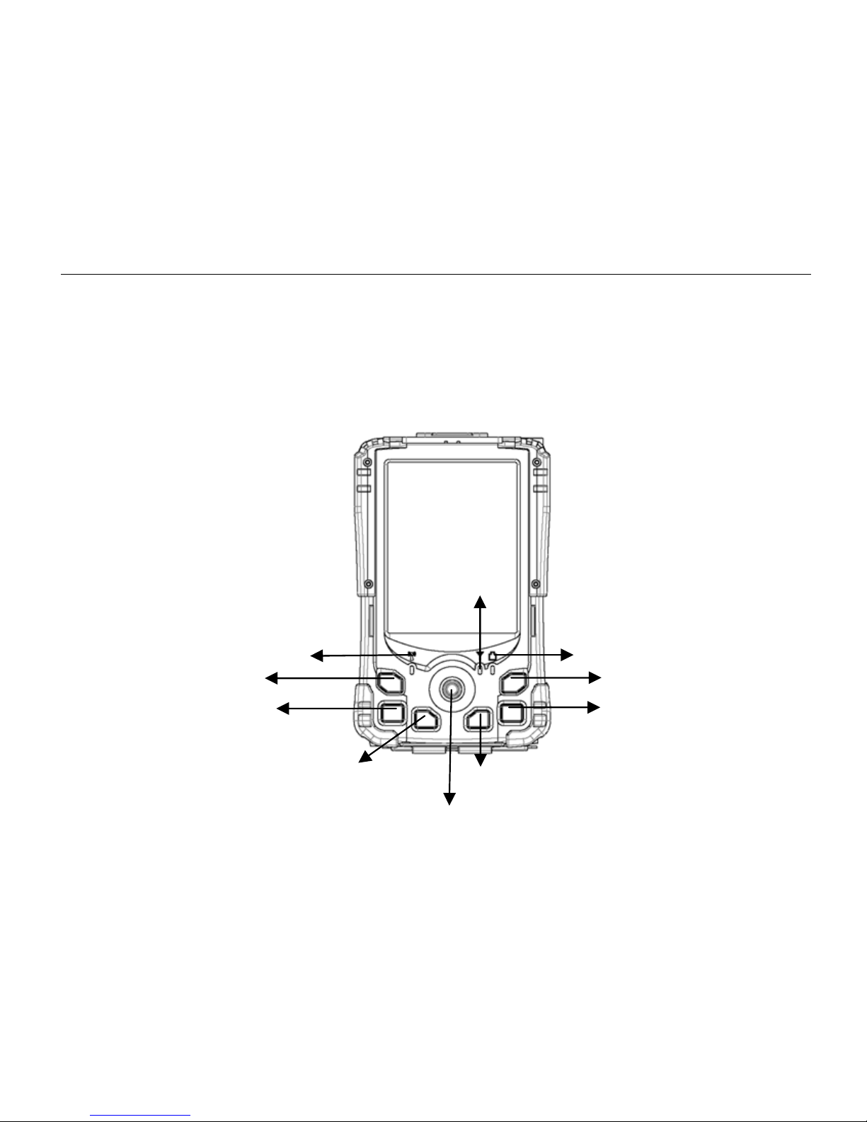
Controls, Indicators, and Ports
Front:
1
2
3
5
4
6
7
8
9
1
0
Page 16

4
1. Wireless ON/OFF (Flight or button 3)
Turn ON/OFF the wireless device
(Option: WiFi, Bluetooth, GPS) Please turn it OFF at locations with wireless
control (hospital, onboard airplane, etc.)
2. Button (User programmable)
3. Button (User programmable)
4. Navigator button
[Left], [Right], [Up], [Down] 4 directions
[Enter] at the center
5. Button (User programmable)
6. Button 4 (User programmable)
7. Power Button
Suspend or Wake up the system.
8.
Battery charging status indicator(Charging: orange, Full: No light)
9.
No this function in WinCE
10. WLAN/Bluetooth indicator(ON: blue)
Page 17
5
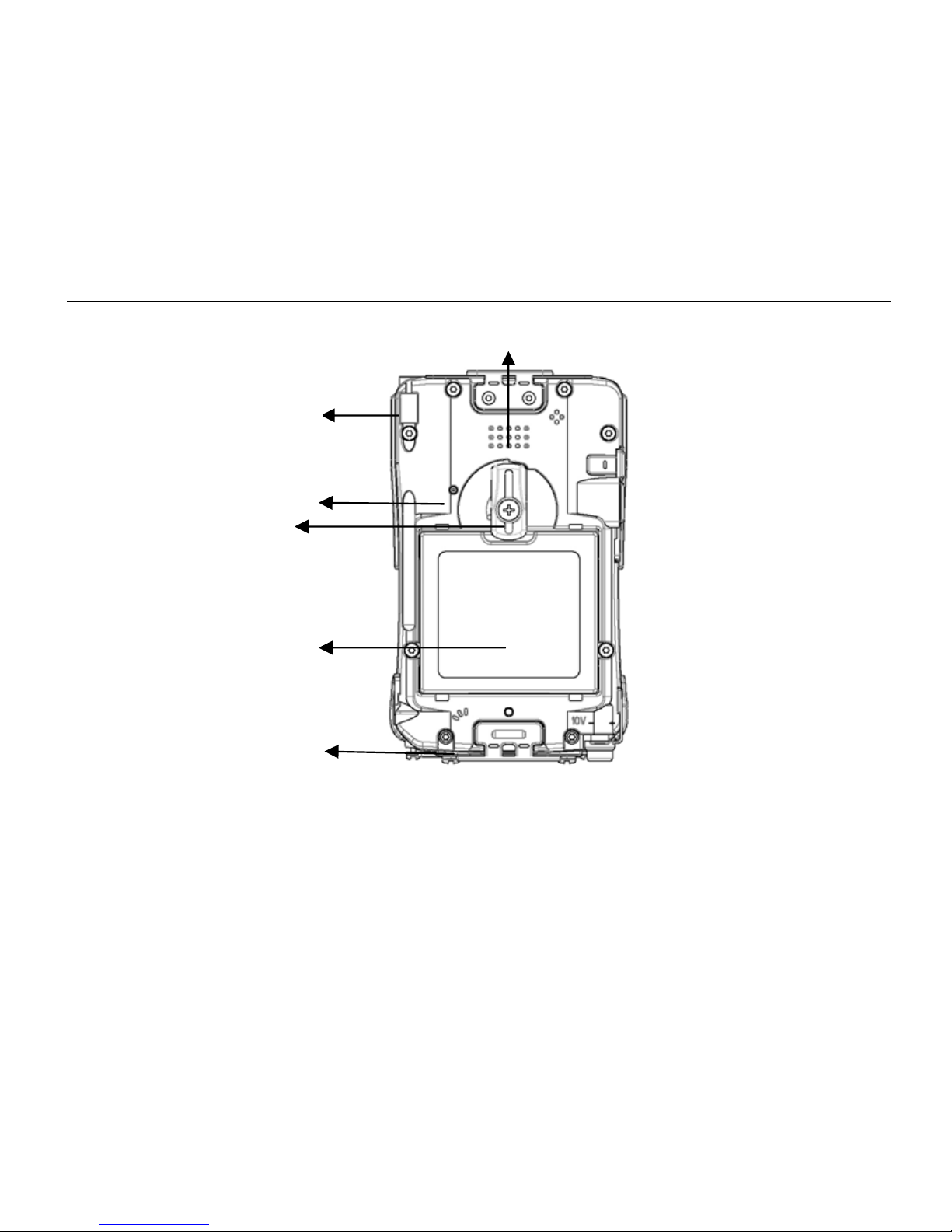
Rear:
1. Speaker (under hand strap)
2. Stylus
3. Reset Button
2
3
4
5
6
1
Page 18
6
4. Battery knob
5. Battery
6. Microphone
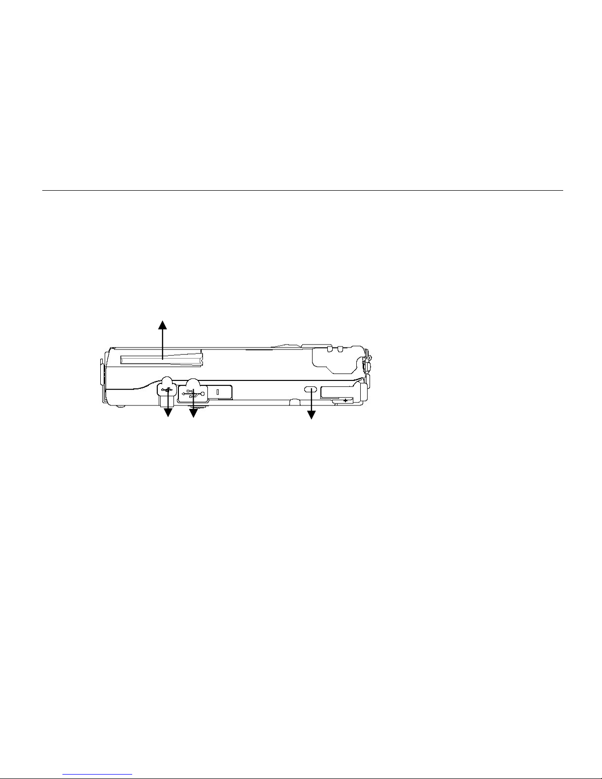
Left:
1. Wireless device antenna
2. USB client port
Data sync with the computer.
3. USB Host port
For Keyboard, USB Flash storage.
4. Kensington lock slot
1
2
3
4
Page 19
7
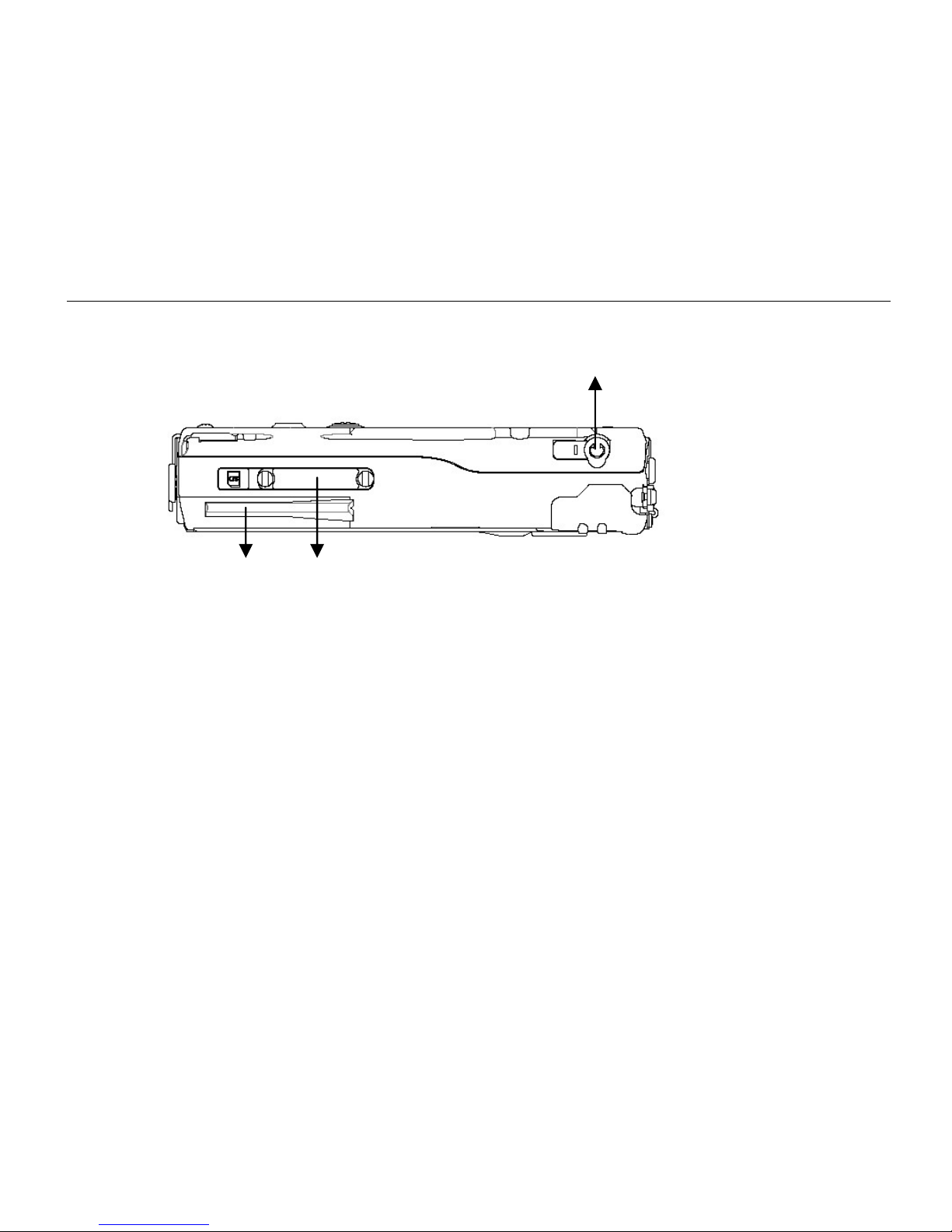
Right:
1. Microphone/Earphone jack
2. SD I/O slot (Secured Digital card and device)
3. 2
nd
antenna (optional)
1
2
3
Page 20
8
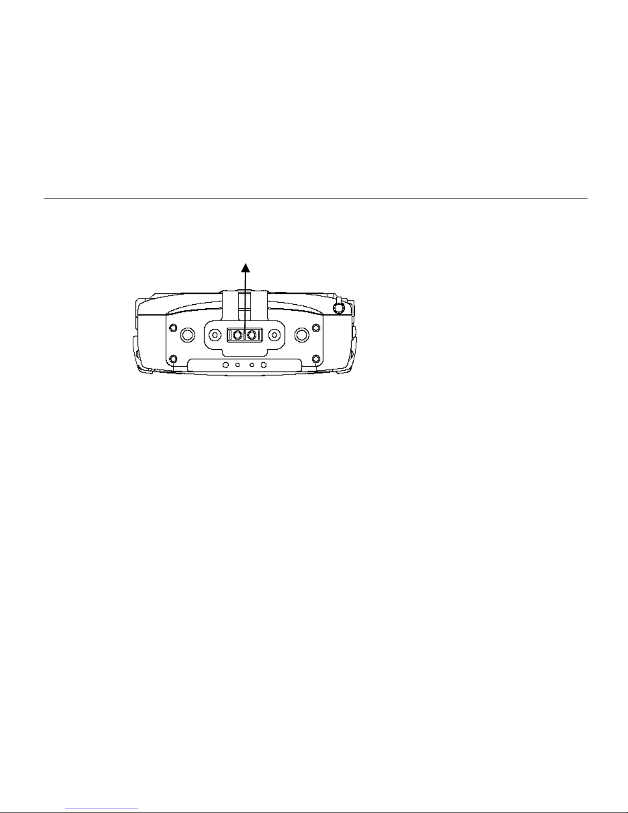
Top:
1. Serial port or GPS antenna
1
Page 21
9
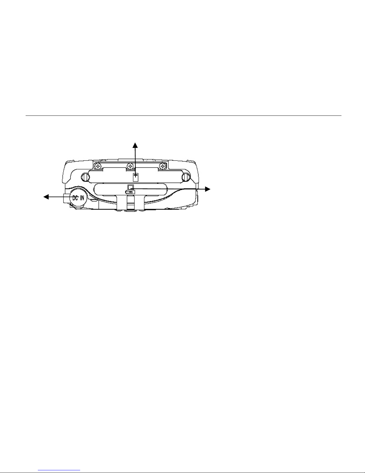
Bottom:
1 DC jack
2 PCMCIA slot
One PCMCIA type II slot
CF (Compact Flash card) will be available by PCMCIA-to-CF adapter
3 Cradle docking connector
Connection to cradle
1
2
3
Page 22

10
Operating Environment and Ruggedness
A clean and moisture-free environment is preferred.
If it is necessary to work in a hostile environment, please make sure all ports are well
protected from dust, moisture, or water. Proper isolation from extreme hazardous
exposure is recommended.
The computer is designed with rugged features of vibration, shock, dust, and rain/water
protection. However, it is still necessary to provide appropriate protection while
exposing to harsh environments.
All connectors will decay or corrode if exposed to water or moisture. Corrosion is
accelerated if the power is ON. Please take proper water-resistant measures for cable
connections.
The DC jack is sealed type which may be operated with water splashing while DC p ower
cord attached. All other port caps should be in place when no cable is attached.
Regularly maintain the computer by cleaning dust, water, etc. will help keeping it in
optimal condition.
Warning: There is no isolated compartment in SD slot, PCMCIA slot, and docking.
These ports must be tightly sealed while working with dust/water.
Page 23

11
COMPONENTS AND FUNCTIONS
AC adapter
When using the AC adapter:
• Use a properly grounded AC outlet.
• Use one AC outlet exclusively for the computer. Having other appliances on
the same line may cause interference.
• Use a power strip with built-in surge protection.
The AC adapter automatically detects the AC line voltage (110V or 220V) and
adjusts accordingly.
Battery
The computer will automatically switch to battery power when the external power
source (AC adapter) is disconnected.
Battery Power Saving Tips
• Turn OFF the LCD backlight when it is visible with external light
• Lower the intensity of the backlight
Page 24

12
• Shut down the computer when not to use for a longer time
Battery Low
When the battery is nearly exhausted, the computer prompts a window warning.
Once the Battery Low warning occurs, please do either or all of the following:
1. Save and close the files you are currently working on
2. Plug in the AC adapter to recharge the battery
3. Swap a charged battery
Charge Battery
1. Plug in AC adapter will charge the battery automatically. If the battery is
already full, the system will stop charge automatically.
2. Dock to optional cradle + adapter will charge b attery, too. Cradle has a battery
slot to charge another battery solely.
3. Connect USB client cable to laptop or PC to charge battery but it needs 15
hours above.
4. The USB client connector on cradle has not battery charging function.
Swap Battery
Page 25

13
To swap the battery:
1. Turn power OFF
2. Turn the battery knob counterclockwise to loose the battery
3. Remove battery from compartment
4. Insert a new battery
5. Press the battery down and turn battery knob clockwise to lock it
6. Press power button to turn ON the computer
Page 26
14
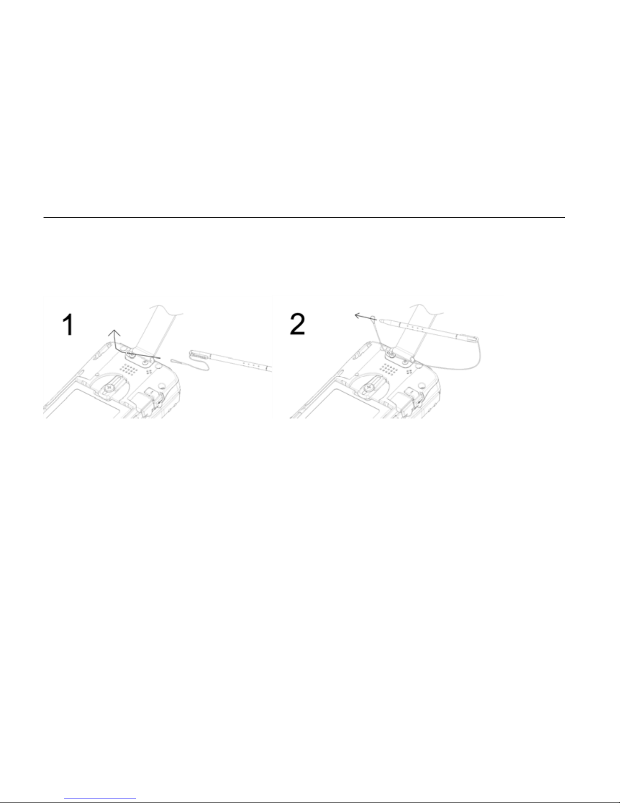
Fix the stylus with tether
Page 27

15
Optional Devices
Cradle (optional)
Cradle is the device for docking, port extension, and battery charging. AC adapter
may attach directly to cradle and charges the computer battery as well as spare
battery.
There is a battery slot on the back of cradle to mount spare battery.
Page 28
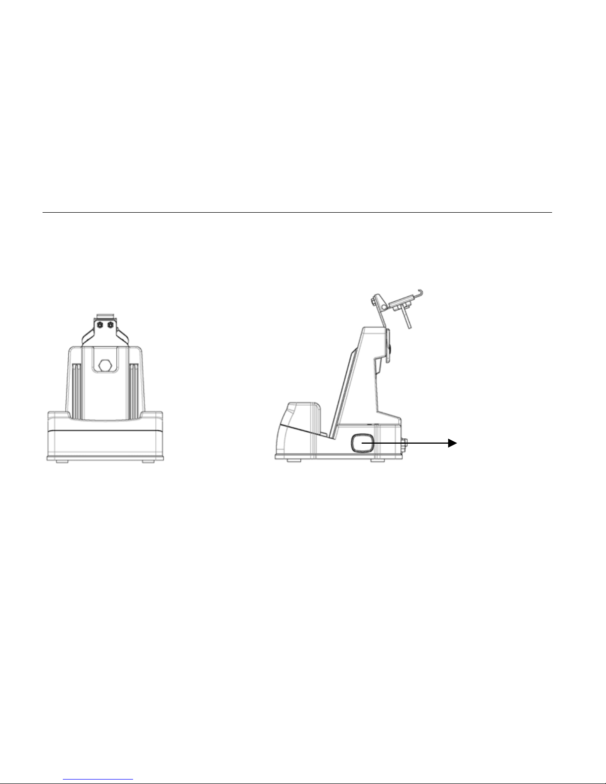
16
Front: Right
LAN/RJ45
Page 29
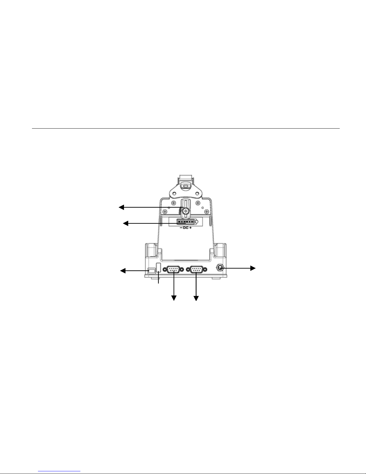
17
Rear
1. Battery Lock
2. Spare battery charger
3. USB Client
1
2
3
4
5
6
7
Page 30

18
4. USB Host
5. DC IN
6. COM port
7. Optional COM port
Mount the cradle:
1. Computer should be power off before docking.
2. Open the rubber cap on the docking connector
3. Align the computer with cradle docking connector
4. Firmly push the computer down to engage the docking connector
5. Turn rotary latch to fix the computer
Remove from the cradle:
1. Turn loose the rotary latch to release computer
2. Pull away the computer either power is ON or OFF
Mount spare battery: (spare battery is optional)
Perform the same procedure as mounting primary battery on computer. Cradle will
charge computer and spare battery simultaneously.
Page 31
19
PCMCIA Slot
The computer accepts one type-II PCMCIA card. Insert the card firmly into the slot
and fix the rubber cover for water/dust protection.
To remove the card, push the eject button to pop out the card. The eject button can
hide into the compartment by pushing it inward gen tly.
It may be necessary to load PCMCIA card driver to enable the function.
Note: If the computer is working with dust, moisture, or water, to be sure to fix the
PCMCIA rubber cap tightly with screws.
SD Slot
The computer accepts one SD card (Secured Digital Card).
Insert the card firmly into the slot and fix the rubber cover for water/dust protection.
To remove the card, push the eject button to release it.
Note: If the computer is working with dust, moisture, or water, be sure to fix the
SD rubber cap tightly with screws.
Page 32

20
BASIC OPERATION
Get Help
Tap Æ Help or get it from companion CD
Get the operation information from the list.
Synchronizing data with PC
Using ActiveSync, you can synchronize information on this device with information
on the PC. ActiveSync is already installed on this device but you need to install it on
your PC if your PC does not have it yet.
Download ActiveSync from this website.
http://www.microsoft.com/windowsmobile/activesync/activesync42.mspx
Follow the instructions to install ActiveSync. Once installation is complete, connect
the sync cable to the device and plug it into your PC USB port.
Page 33

21
Resetting the DA05
Soft Reset
To do a soft reset will delete any data that has not been saved in the ROM. But your
saved files and programs are not deleted.
Try a soft reset if the device does
not respond when you tap the display or press a button. To do a soft
reset, use the stylus to press the reset button on the rear.
Hard Reset
Notice: To do a hard reset will delete all the data stored in DA05 flash
memory and any programs installed on DA05.
Page 34
22
Do a hard reset if
z You want to restore the device to factory default settings.
z You forget the password and need to reset it.
z Your device is experiencing severe operational problems and you have
attempted a soft reset.
To do a hard reset
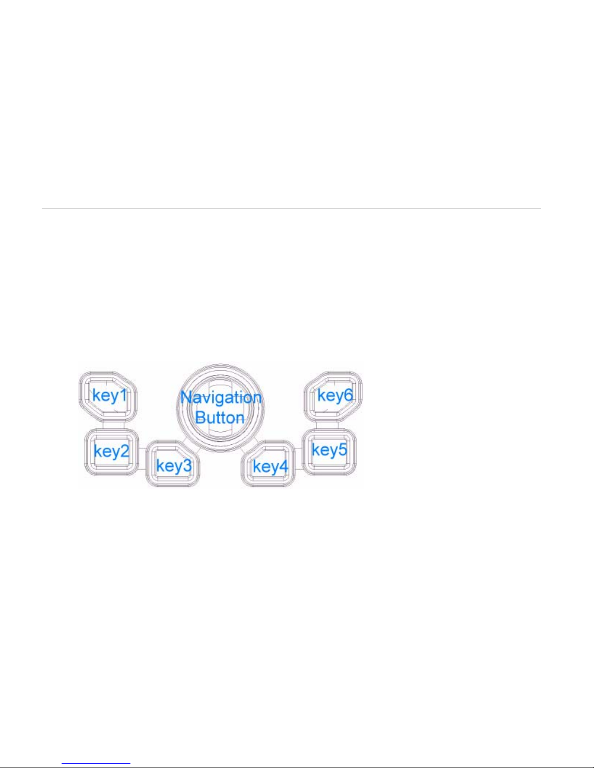
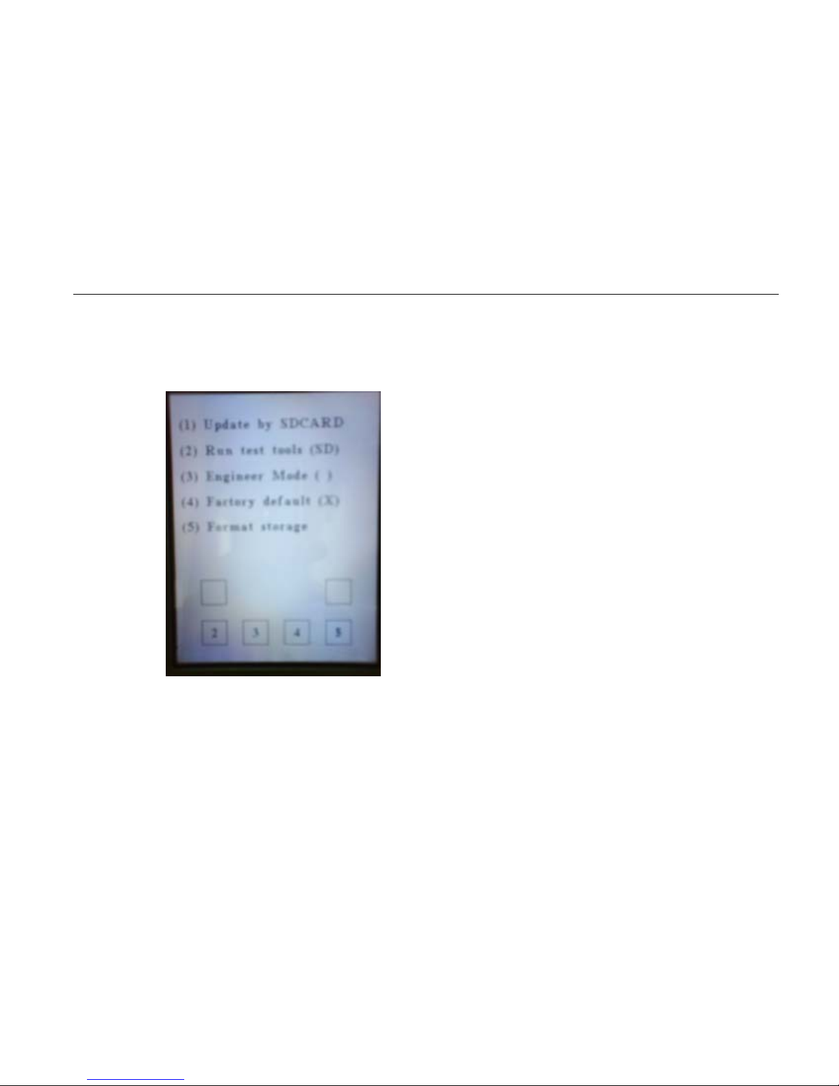
1. Press and Hold Key4 and use stylus to tape reset button (on the rear).System
will enter Eboot mode.
2. Press Key5 to format Storage.
Page 35
23
3. Use stylus to tape rest button(on the rear) to reboot System
Page 36

24
Using Wireless LAN (option)
Connect to Internet:
Turn on the Wireless Signals.
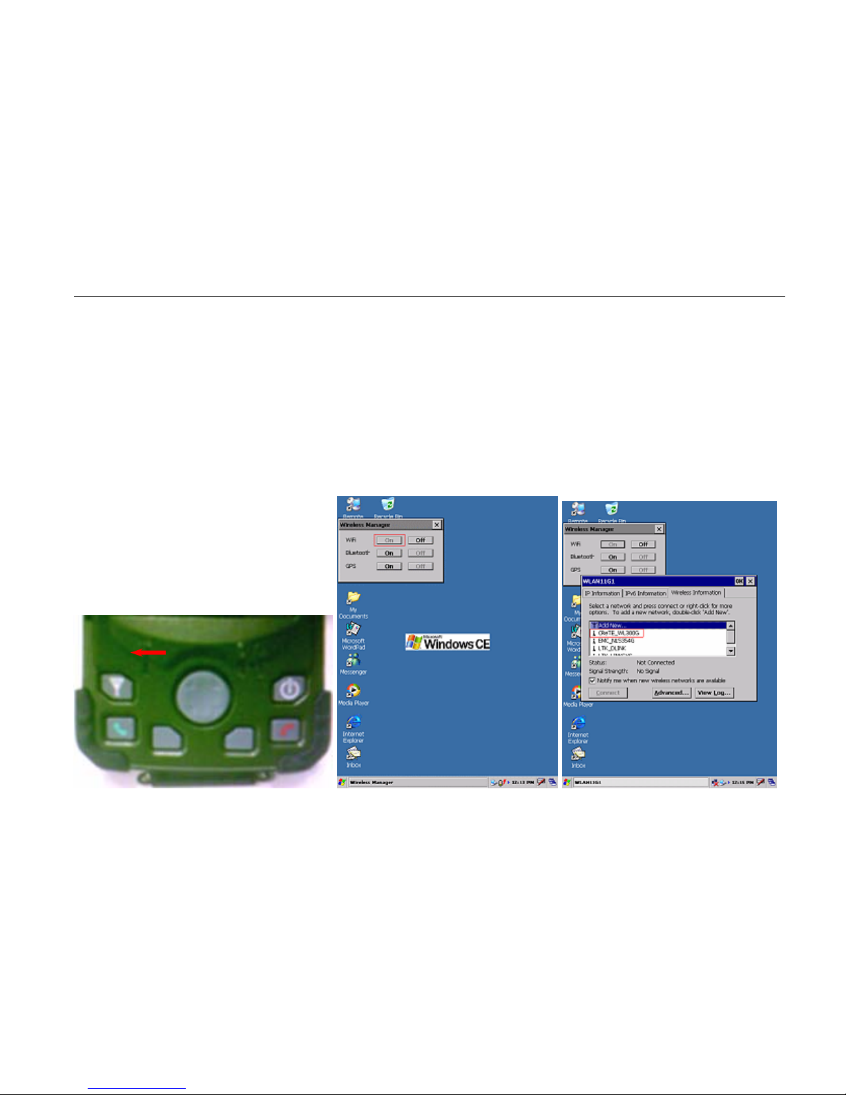
1.1 Press “Wireless” button on the DA05 keypad and screen will pop up a
“Wireless Manager” dialog. (Figure 1-2)
1.2 Tap “On” button to enable wireless function and screen will pop up a
“WLAN11G1” dialog. (Figure 1-2 & Figure 1-3)
1.3 Select a property wireless AP as “Figure 1-3” is called “CreTE_WL300”.
1.4 Tap “Connect” button and it prompts you a “Wireless Network Properties”
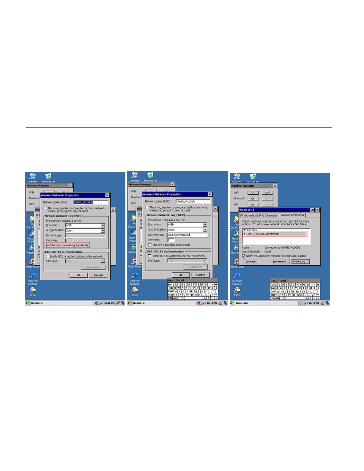
dialog.
1.5 Select “The key is provided automatically” checkbox to disable. (Figure 1-
4)
1.6 To input correct password on “Network key” item to make wireless
Page 37
25
function available. (Figure 1-5)
1.7 If you enter “Network key” is correctly then you can see “CreTE_WL300”
icon shown connected status. ( Figure 1-6)
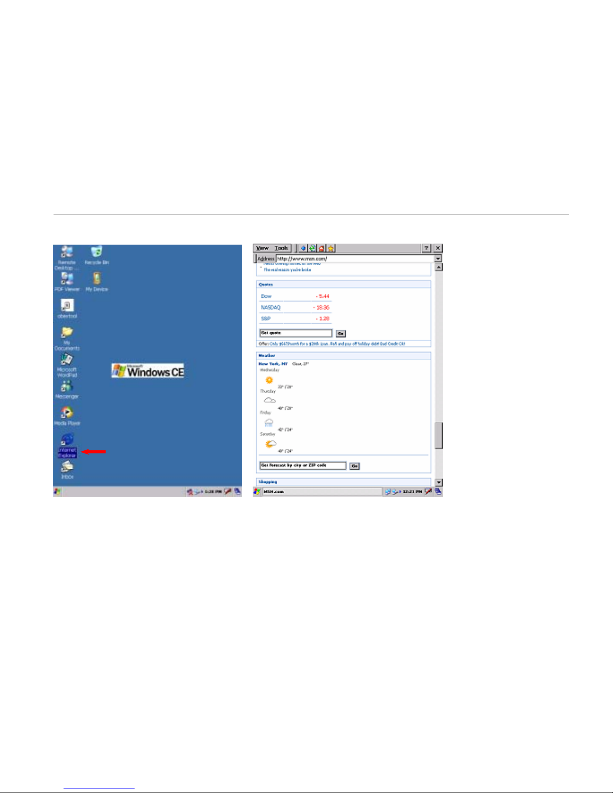
1.8 Now you can use “Internet Explorer” to surfer World Wide Web that for
you want. ( Figure 1-7 & Figure 1-8)
Page 38
26
1.1 1.2 1.3
1.4 1.5 1.6
Page 39
27
1-7 1.8
Page 40

28
Using Bluetooth (option)
Turn on the Wireless Signals.
1.1 Press “Wireless” button on the DA05 keypad and screen will pop up a
“Wireless Manager” dialog.
1.2 Tap “On” button to enable Bluetooth function
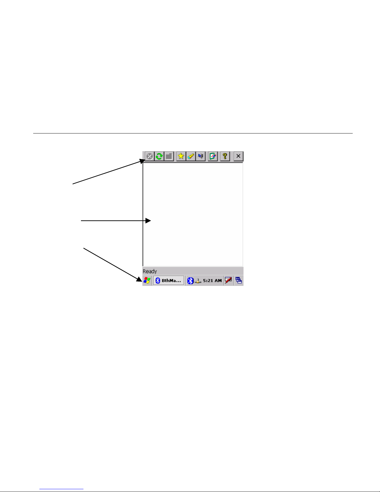
1.3 When the bluetooth manager is run, a new window appears and a bluetooth
icon appears in the task bar. This window contains a toolbar with some
icons, a status bar, and a list window :
Page 41
29
Tool Bar
List Window
Status Bar
Page 42
30
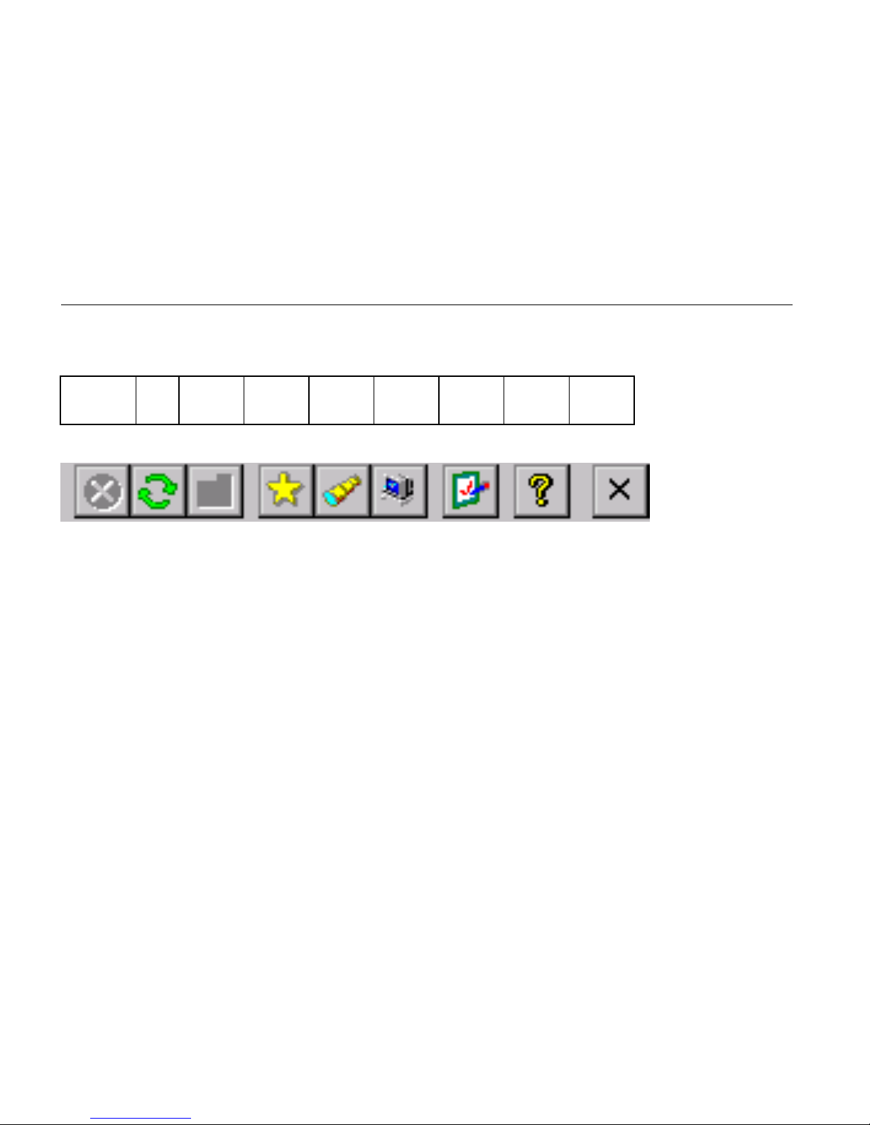
The toolbar
1 2 3 4 5 6 7 8 9
1 Stop the current action
2 Refresh
3 Parent Folder(FTP)
4 Show favorite list
5 Show distant devices
6 Show the about box
7 Configure the application
8 Show local service
9 Shut down
Page 43
31
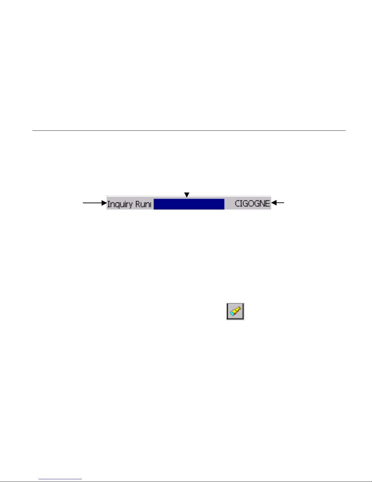
The status bar
State : What the bluetooth manager is doing
Working indicator : For long task (Inquiry, Connection)
Distant device : With which device the bluetooth manager is currently connected
Inquiry devices
When the application is started, you need to click on to start inquiry remote
Bluetooth devices. The devices found are shown in the main window. They are
State
Working indicator
Distant Deivce
Page 44
32
represented by an icon (showing what class of device they are: computer, laptop,
pda, audio device) and the name of the device.
Once you have clicked one time on
all futures clicks will show devices without
inquirying (to decrease search time). To inquiry again remote bluetooth devices you
must refresh the list by clicking on
. (Note : All the coupled devices are shown
without inquiry)
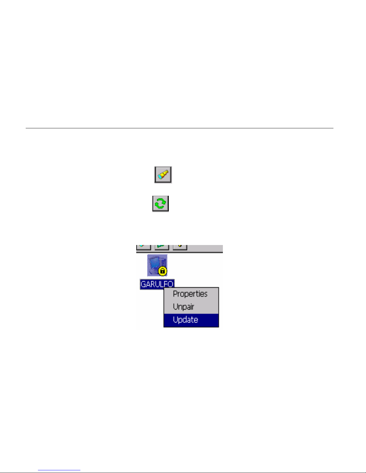
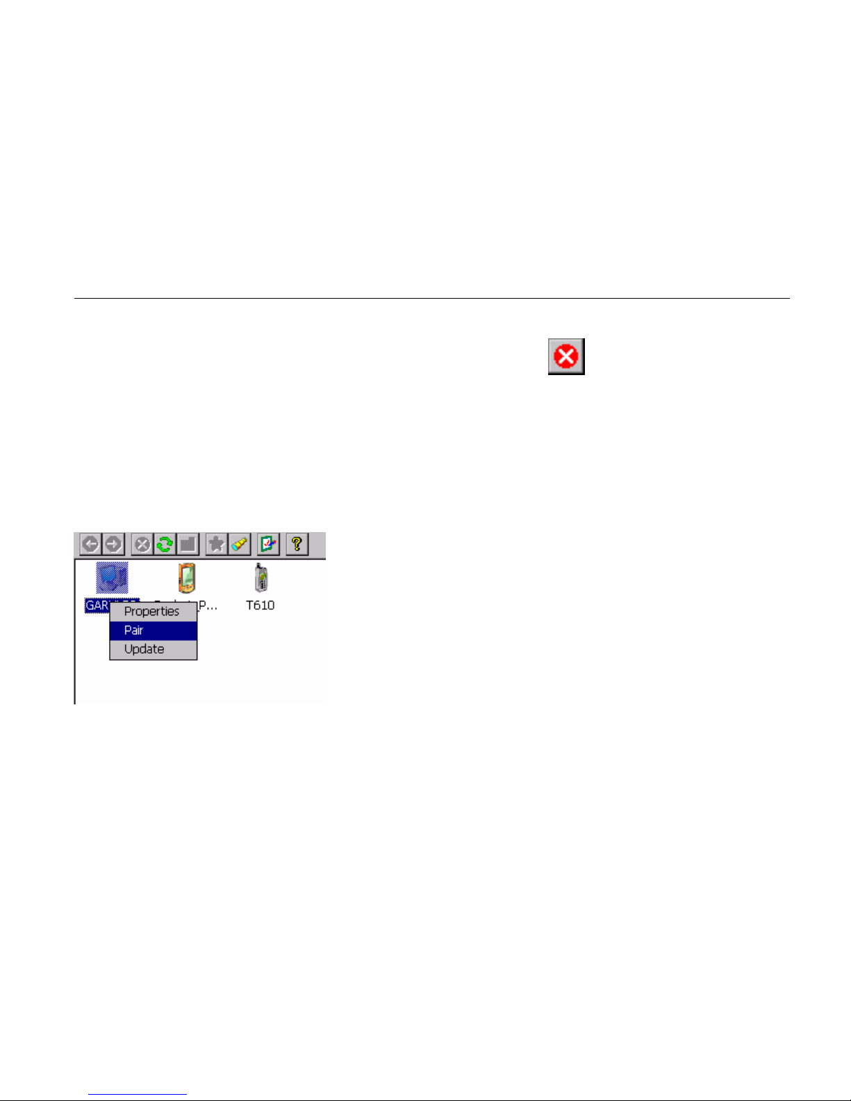
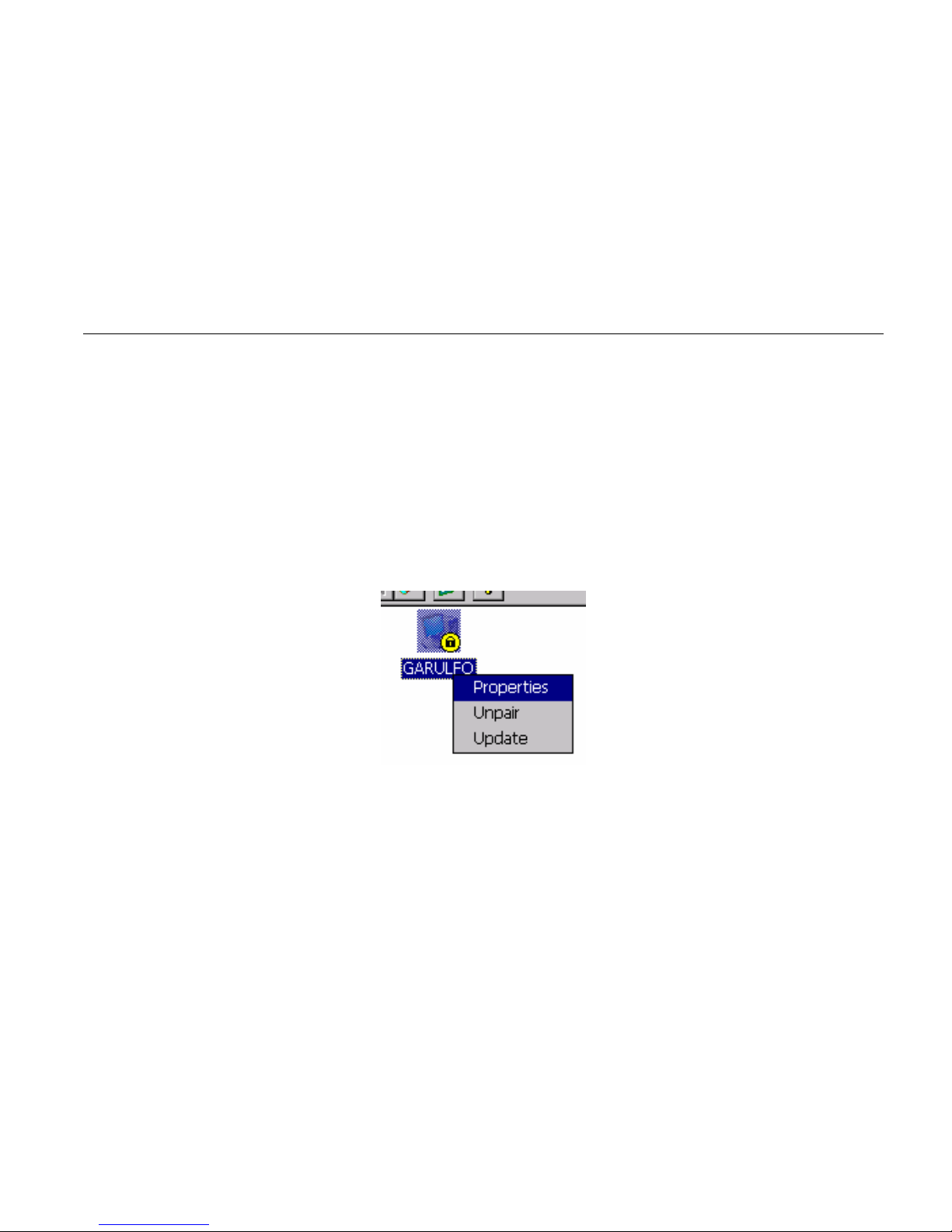
In the list, after an inquiry, some device class and name can be not found. You can
update this by right clicking on the device and select update in the contextual menu:
Page 45
33
During an inquiry, you can stop it by clicking on the the icon.
Device pairing
The device pairing can be done in three ways :
• We want to be paired with another distant device
For that the distant device must be in the list window to be paired with the current
device. Right click on the selected device and click on pair
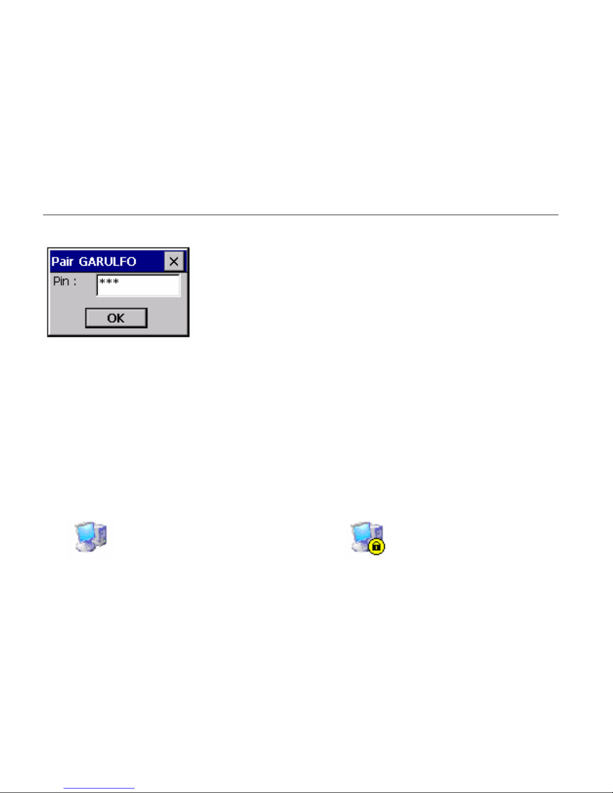
A new window appears to insert the pin code. The pairing can be canceled by
clicking on the close button or started by clicking on the OK button (after typing a
pin code).
Page 46
34
• A distant device try to pair with the current device (with no Auto Pin
Code)
When a device try to pair with the current device, a new window appear to enter the
pin code selected by the distant device.
• A distant device try to pair with the current device (With auto Pin Code)
In this case, the user is not invited to type a pin co de. It is automatically typed for
him.
After the pin code is typed (or auto typed), there is two issues :
Device is not paired Device is paired
Page 47

35
Properties and configuration
Local services
General
In the Bluetooth Manager v1.5, there are three local services proposed to distant
devices:
SPP (Serial Port): A distant device wants to establish a serial connection with the
local device
OPP (Object Push): To receive files and contact information card
FTP (File Transfer): To access to local directories, files and upload files and create
directories
Note : the OPP and FTP profil cannot be separated : You cannot deactivate one
without deactivate the second.
Click on
, to administrate local services. Local services are shown in the list
view with a specific icon and an explicit name.
Page 48
36
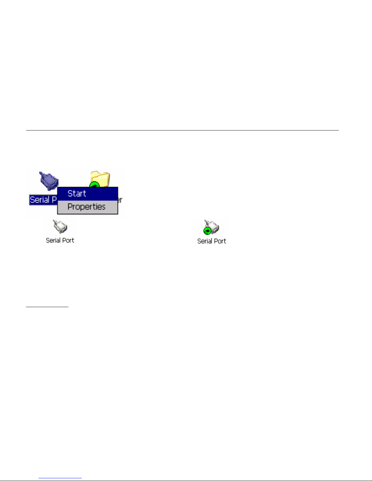
You can activate or deactivate a local service by double-clicking it or by right
clicking it and selecting the Start or stop item from the contextual menu.
The local service is not
activated
The local service is activated
You can also configure the service by selecting the Properties Item when you right
click him.
SPP Profile
Load the SPP Server :
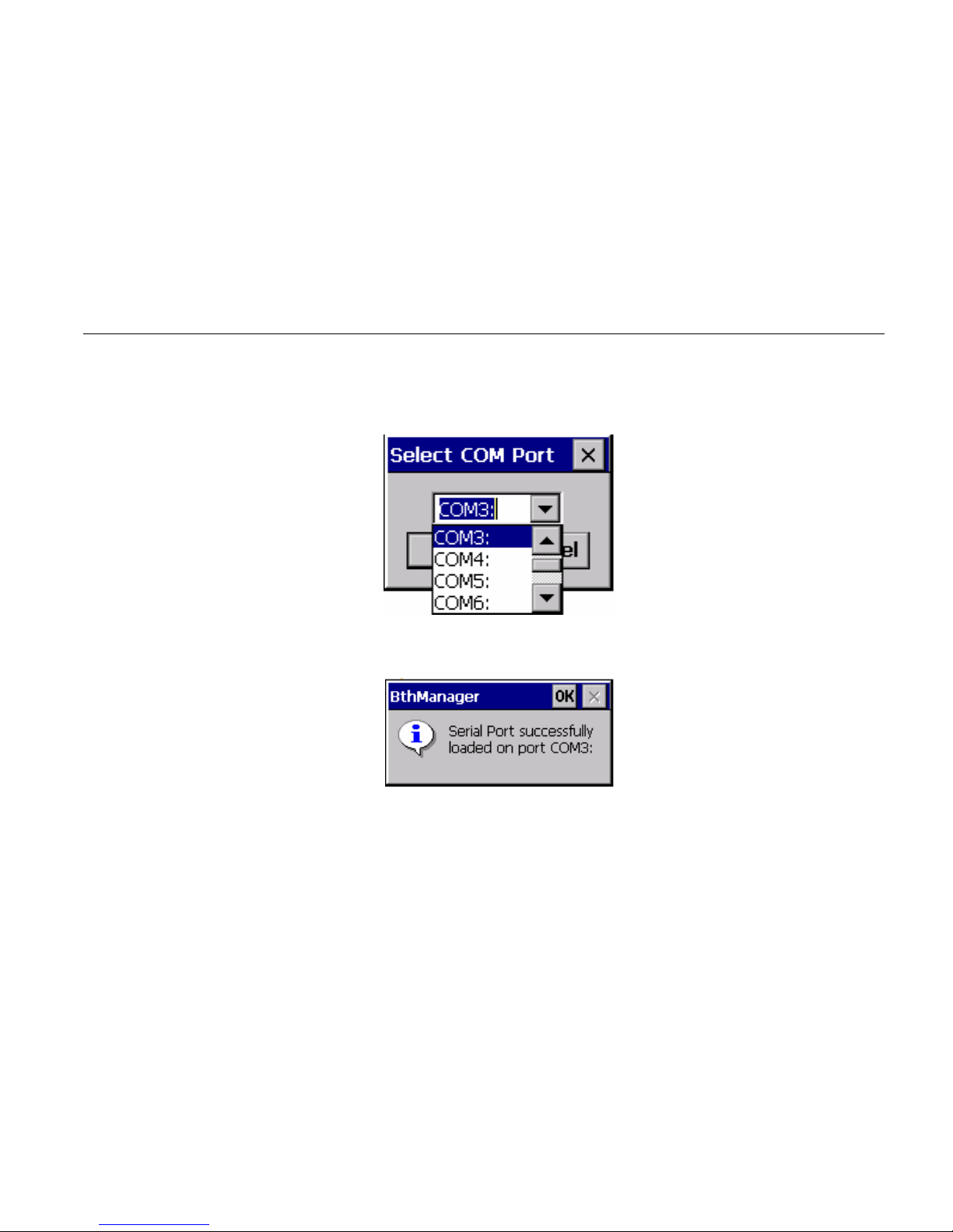
If the Auto Server COM Port is not checked (cf. 0.
Page 49
37
Application properties)
• The application shows a dialog box with all the available port COM
• Select the COM Port to be mapped with the SPP Server
• The Serial Port profile is activated
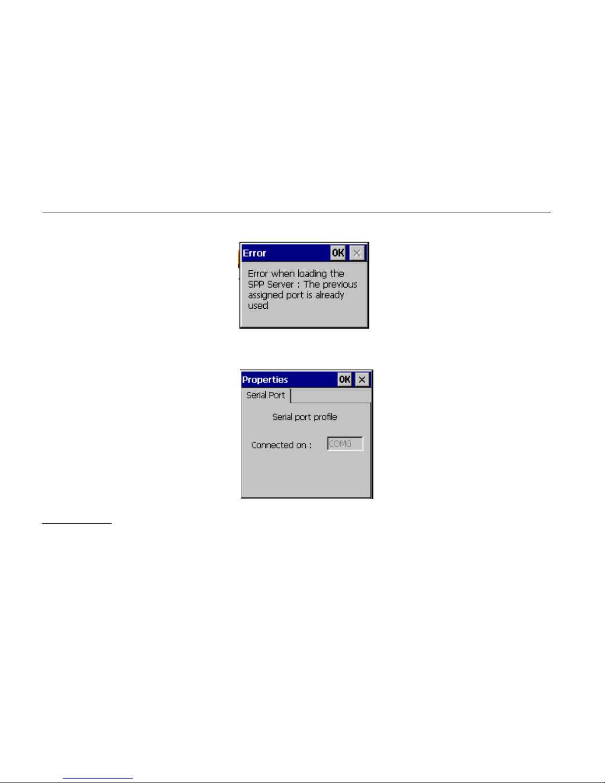
If the Auto Server COM Port is checked, the serial Port profile is activated with the
last used COM Port for the SPP Server profile. If it is not available, an error appears.
Page 50
38
If the service is connected you can know the COM port assigned by
selecting “Properties” in the contextual menu of the service.
FTP Profile
Page 51
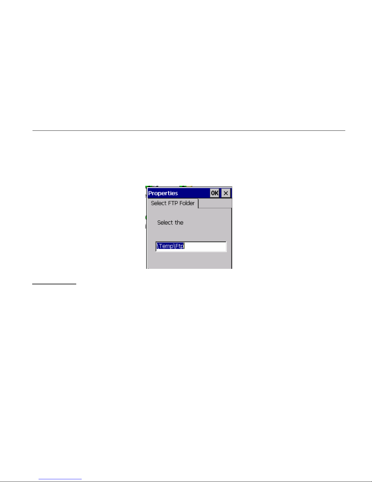
39
You can change the directory of the FTP server (directory seen by distant device) in
the service properties (Contextual menu)
OPP Profile
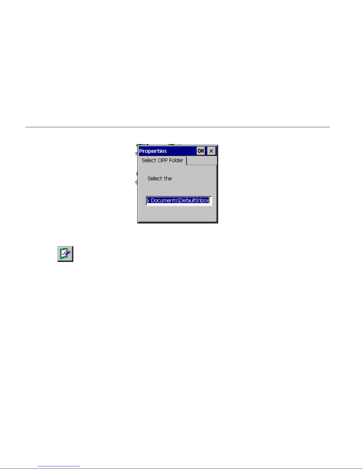
You can change the directory where the File sent by distant device will be
put.
Page 52
40
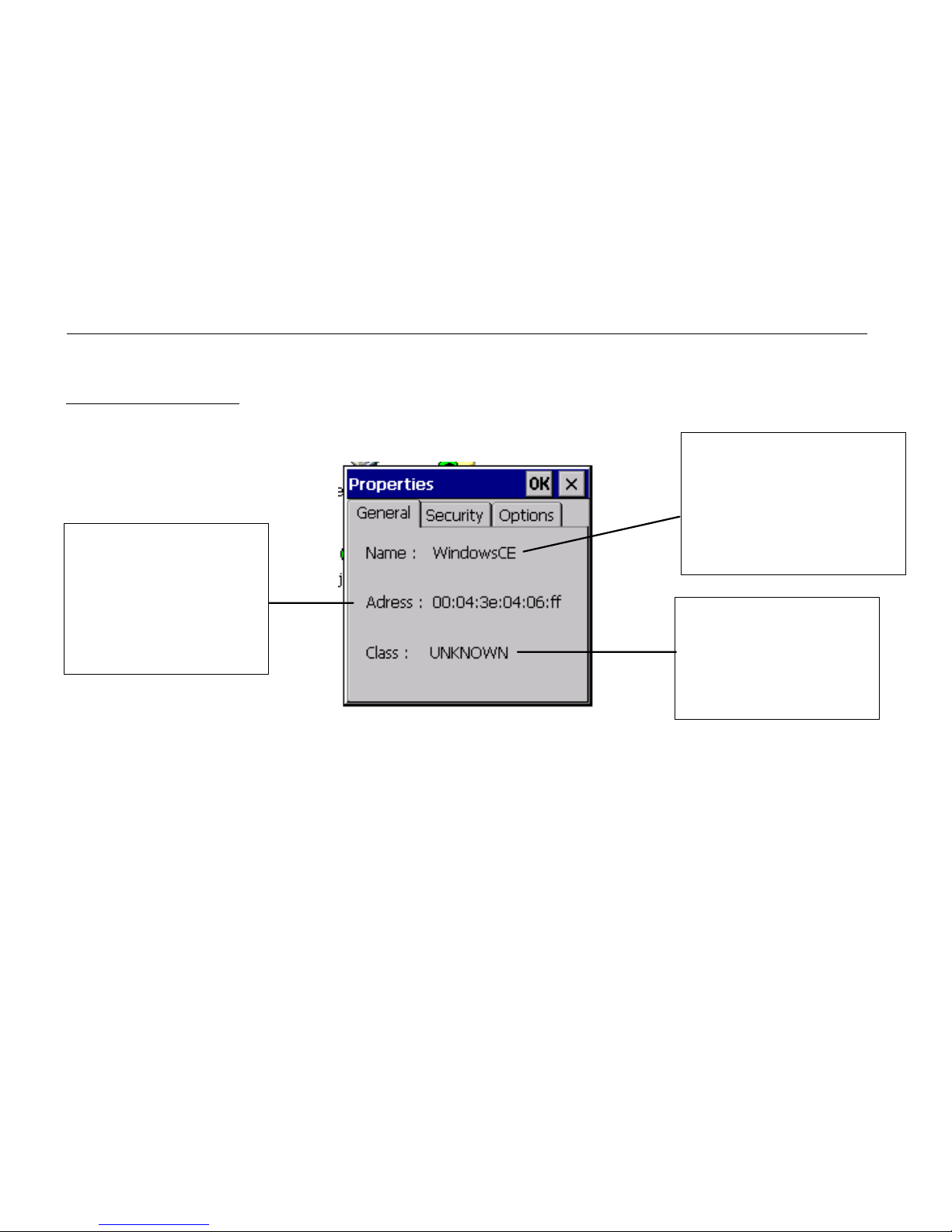
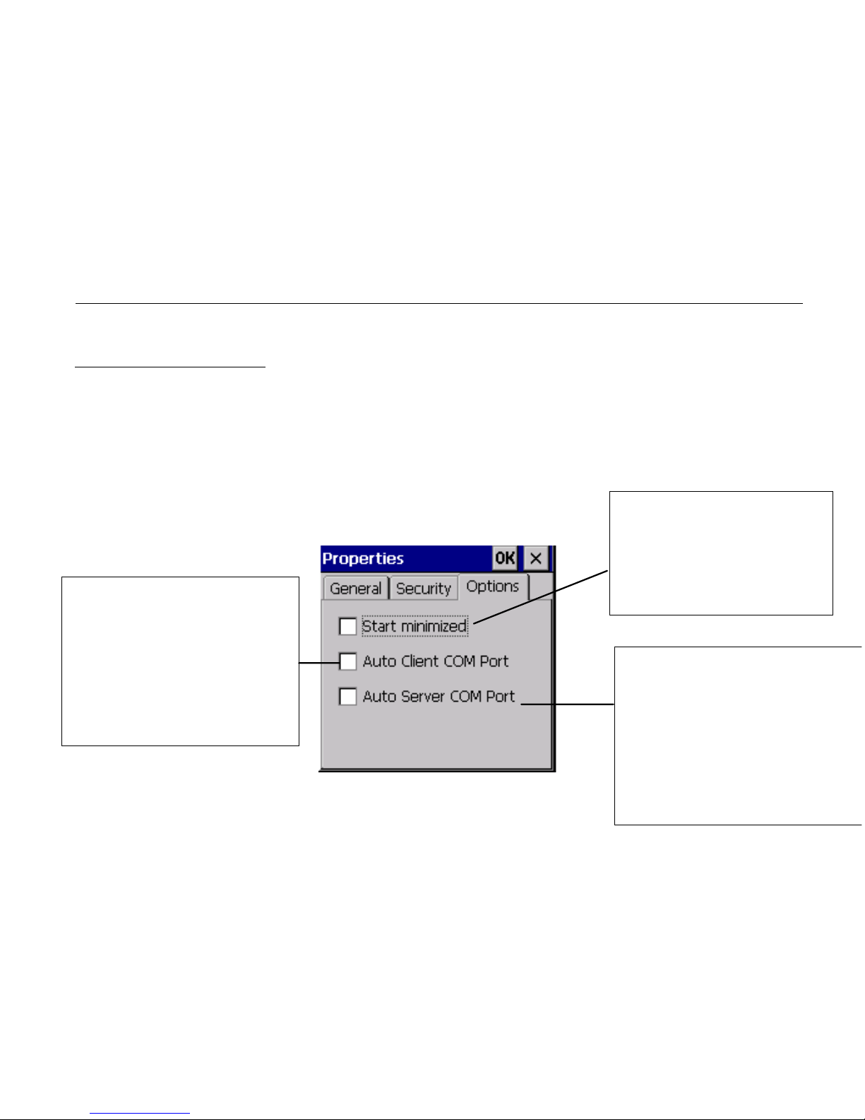
Local device properties and configuration
Click on , to see:
• the local device properties (MAC address, name and device type)
• application option (start minimized, Auto assigned COM port number
for client SPP and server).
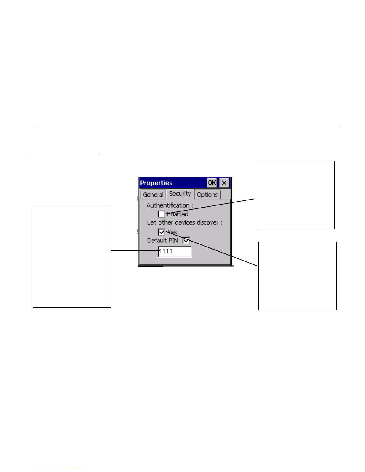
• security options of the bluetooth manager
Page 53
41
Security properties
Don’t show a
window when a
distant device
wants to be
paired. Auto type
the PIN code
number
Distant devices
must be paired to
access local
service
The current
device is visible
or not from other
devices
Page 54
42
General properties
MAC address of
the current
device devices
Name for distant
device of the
current device
Class of device of
the current device
Page 55
43
Application properties
Check this if you want
to affect the first
available COM port to a
SPP client connection
Check this if you want
the Bluetooth manager
starts minimized
Check this if you don’t
want a dialog appears
when you start the SPP
server(to select the COM
port)
Page 56
44
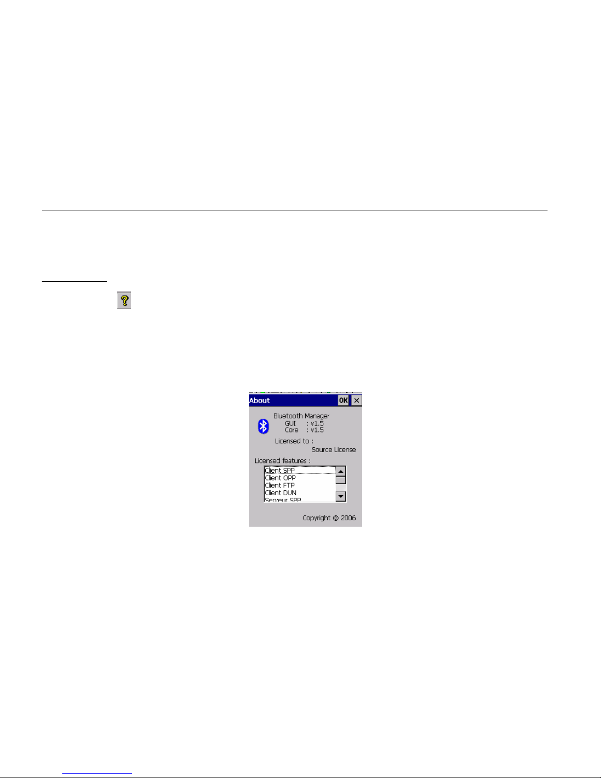
About Box
Click on the
icon if you want some general information about the bluetooth
manager:
• Version
• License information
Page 57
45
Distant device properties
You can have general information on a distant device (like the General tab of the
Local device properties) by selecting “properties” in the contextual menu of the
distant device.
Page 58
46
Distant services
Services Inquiry
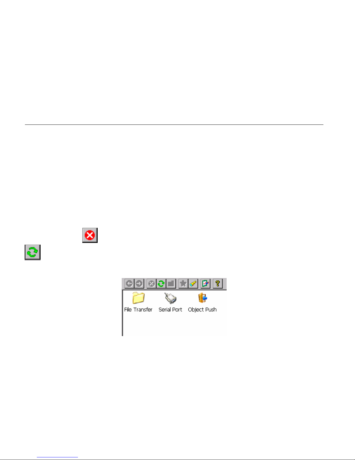
To inquiry the services available on a distant device, you have to double click on this
one. After that, the bluetooth manager inquiries (it indicates this in the status bar) for
all the services (among SPP/FTP/OPP/DUN) of the distant device. You can stop the
inquiry with the
icon. You can also refresh the list of services by clicking on the
icon.
Page 59
47
File Transfer
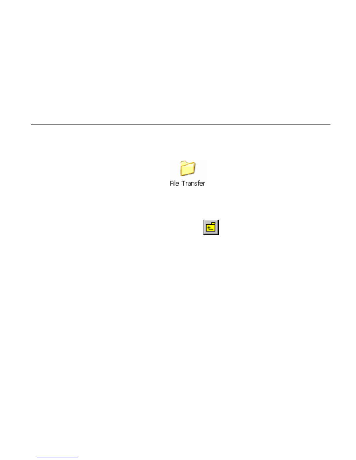
To use this service, double click on the icon or choose connect on the
contextual menu (right click). Then, the bluetooth Manager tries to connect to the
distant service. If the connection is successful, the root directory shared by the distant
will be shown in the list view. You can browse the device by double clicking on the
remote folder and go to the parent directory with
.
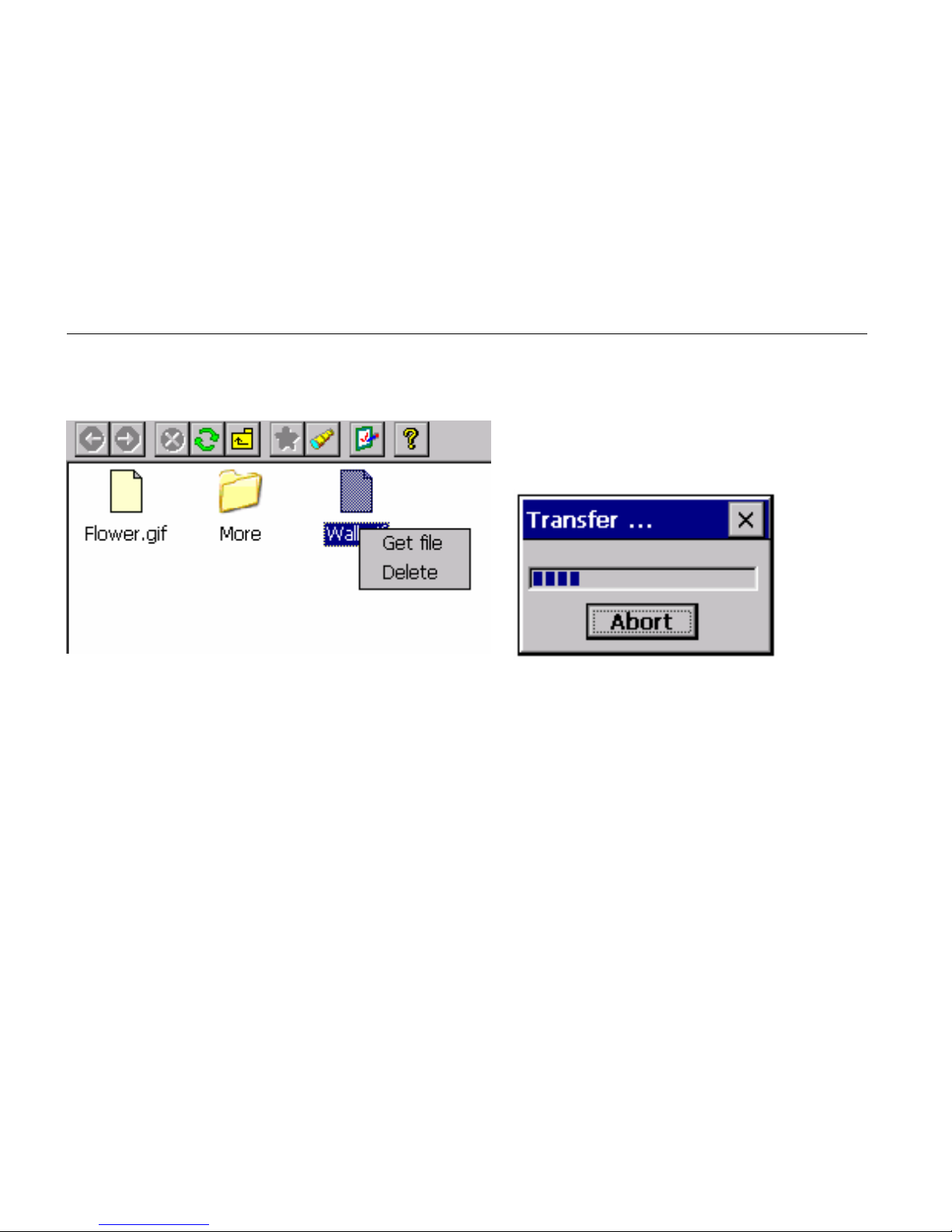
To get a file, double-click or choose “Get File” from the contextual menu. A window
is displayed to indicate the transfer state.
Page 60
48
The file is downloaded by default to the “\My Documents\Bluetooth\Ftp” directory.
You can change this one with the FTP properties (contextual menu of the File
Transfer service).
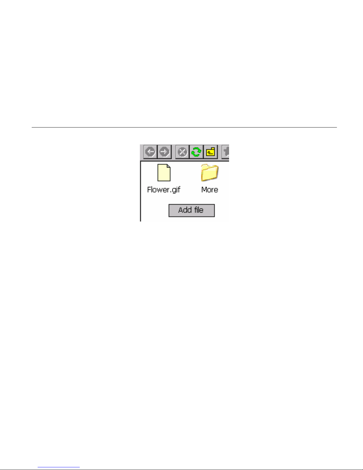
You can upload a file to the distant device by right-clicking on a whitespace of the
listview and select Add file.
Page 61
49
You can also delete a file by selecting delete on his contextual menu.
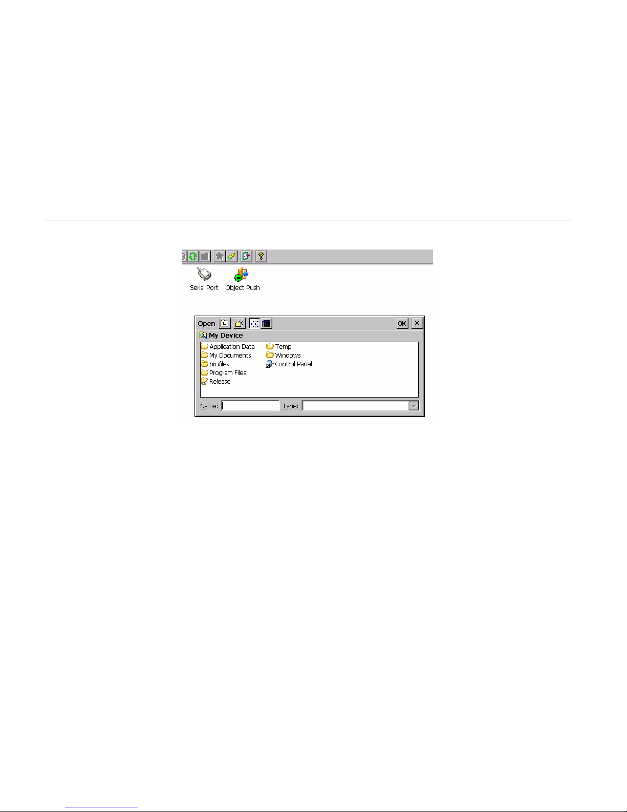
Object Push
To use this service, double-click on the distant service or select “Push file” on the
contextual menu. Then you can choose the file to transfer.
Page 62
50
Serial Port
To use this serial service, double-click on the icon or choose “Connect” from the
contextual menu.
If the Auto Client COM Port is not checked (cf. 0.
Page 63
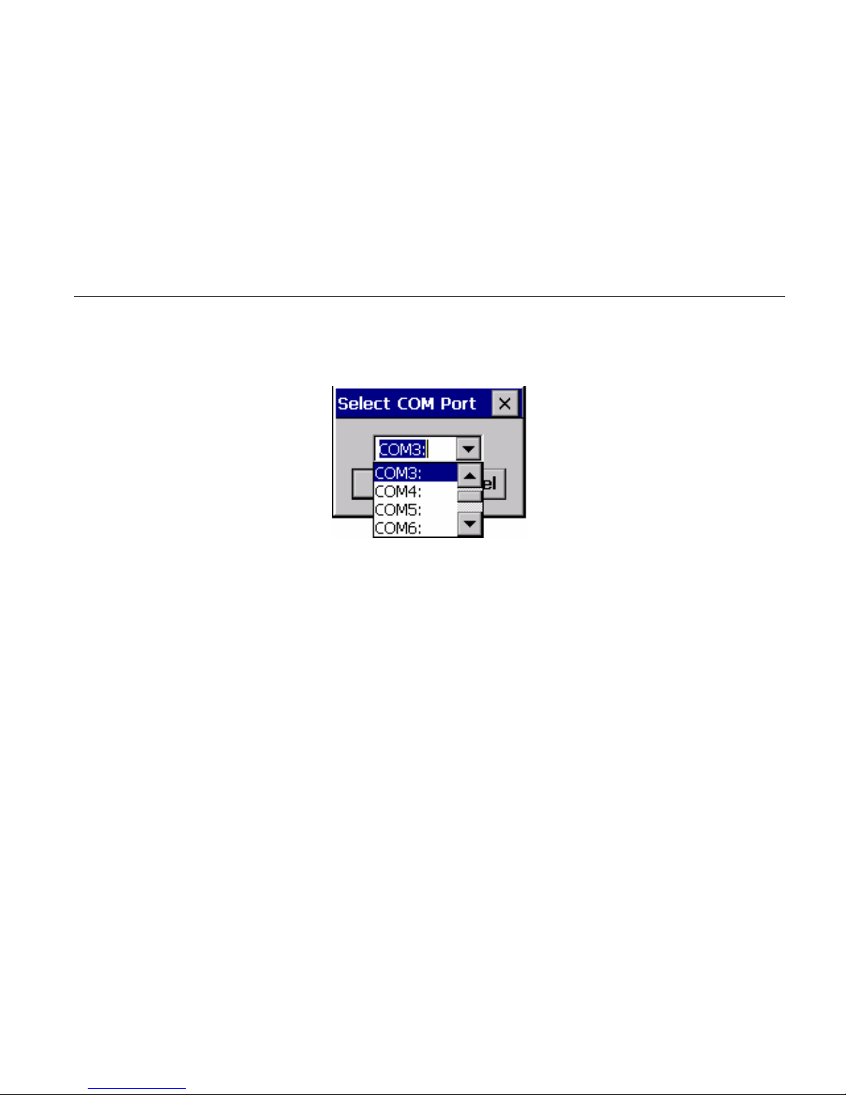
51
Application properties)
• The application shows a dialog box with all the available COM
If the Auto Client COM Port is checked (cf. 0.
Page 64
52
Application properties)
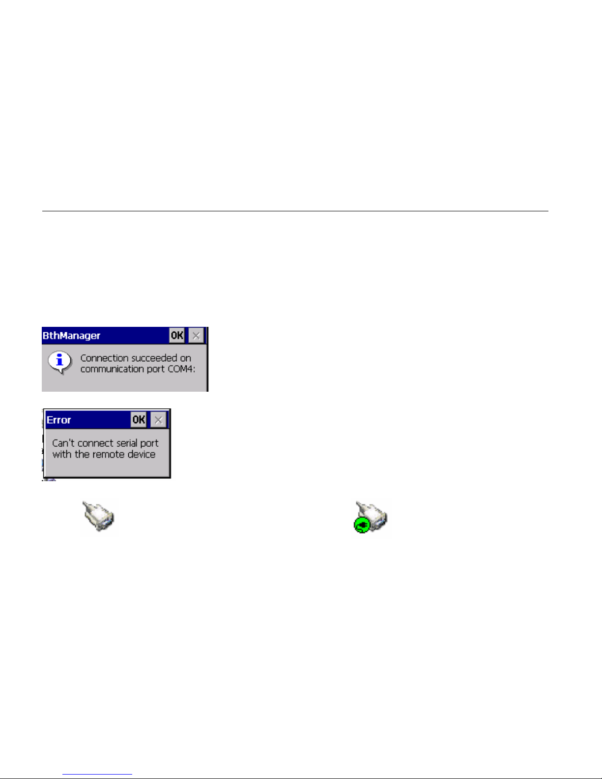
• The Application selects automatically the first avalaible COM port in the
system.
If the connection is successful a messagebox appears:
else an error message appears
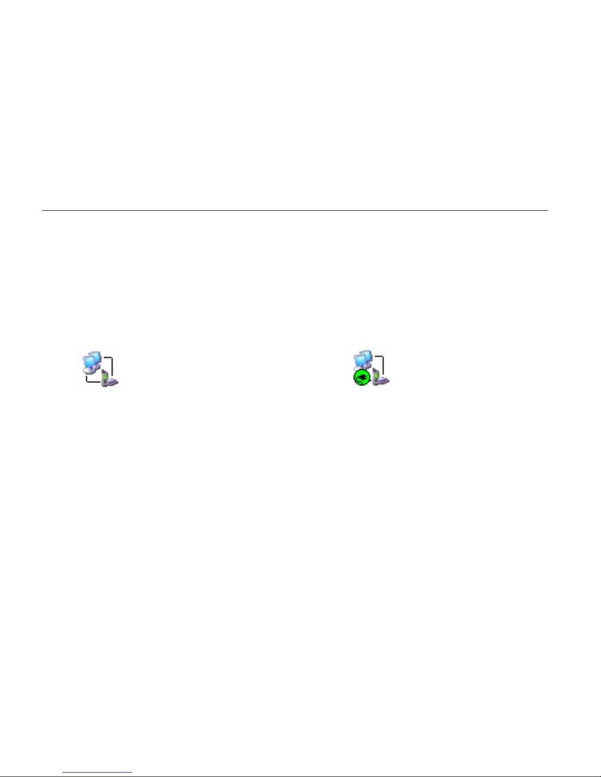
The status of the service (connected or not) is displayed as shown below:
Service not connected
Service connected
Page 65
53
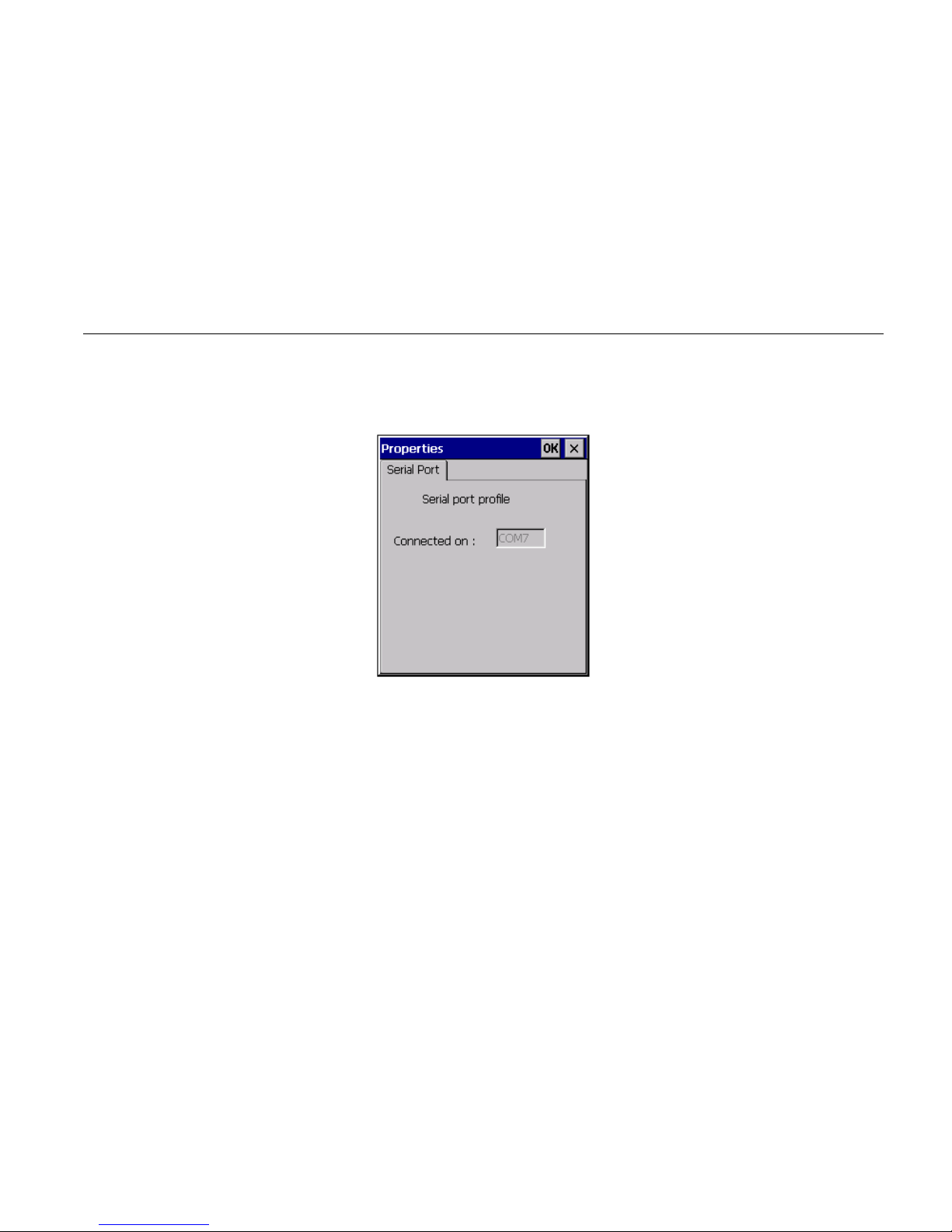
When the service is on, all applications could use the virtual COM port. To know the
COM port setting, select properties in the contextual menu.
When connected, the Manager can still be used as usual.
Page 66
54
Dial-Up Networking
To use the Dial-up Networking service, double click on the icon or choose "Connect"
in the contextual menu. The first avalaible COM port in the system is assigned to the
DUN profil on the selected device.
The status of the service (connected or not) is displayed as shown below:
Service not connected
Service connected
When connected, the Manager can still be used as usual. A modem associated to the
COM port used by the service is created and can be used to establish a Dial-Up
connection. To know the COM port settings, select properties in the contextual
menu.
Page 67
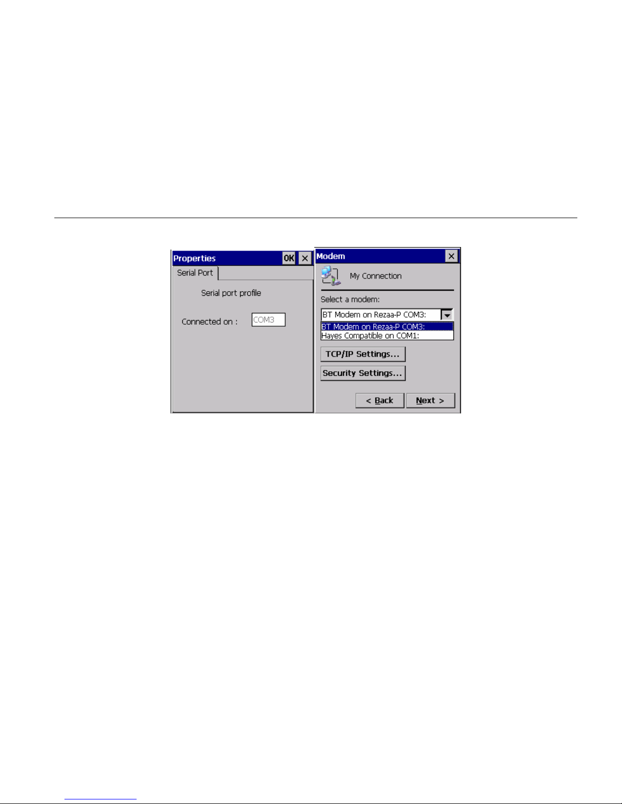
55
The modem created by the Manager is displayed in the list of available modems for
Dial-Up connection when making a new connection ("Make New Connection" icon
in the "Network and Dial-Up Connection" system window).
Page 68

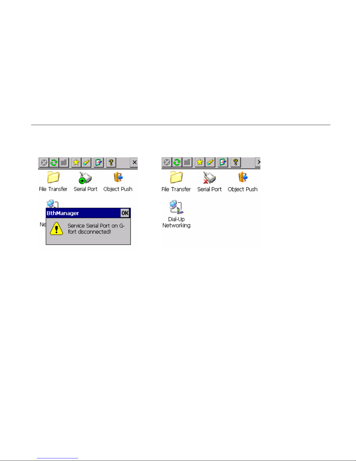
56
Distant disconnection management
When a connection, previously established, is shut down by the distant host (manual
disconnection or connection loss due to distant device shutting down or due to a
weak signal), the user is notified of the disconnection and the Manager attempts to
reconnect during a time t (by default, 1min30). The notification is made by a pop-up
window and by changing the icon associated to the disconnected service.
Page 69
57
Connection shortcuts management
Shortcuts associated to defined services on defined devices make establishing
connections with distant devices easier. A shortcut can be created by selecting the
Page 70
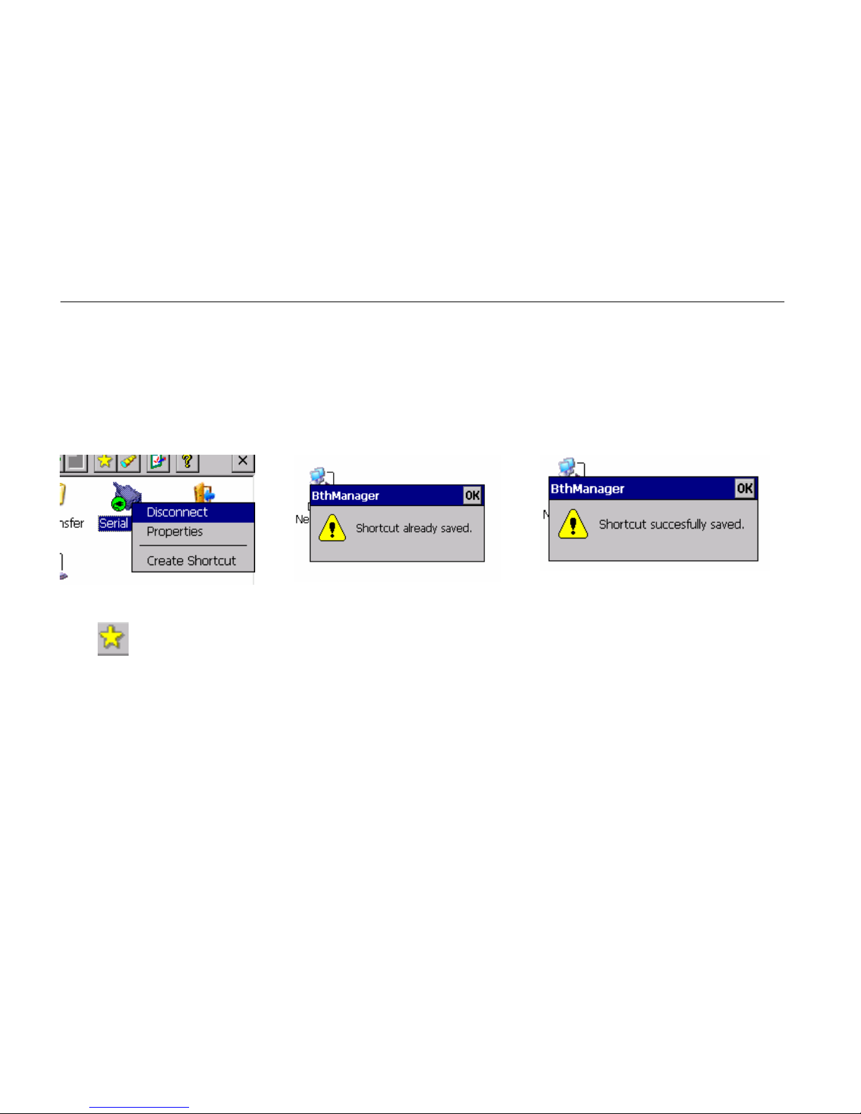
58
"Create Shortcut" item in the contextual menu of a connected service. If the shortcut
already exists, a notification is displayed. If the shortcut is successfully created, a
notification is also displayed.
The button in the tool bar displays the connection shortcuts list. The service, the
device and, eventually, the COM port are used in the shortcut name.
Page 71
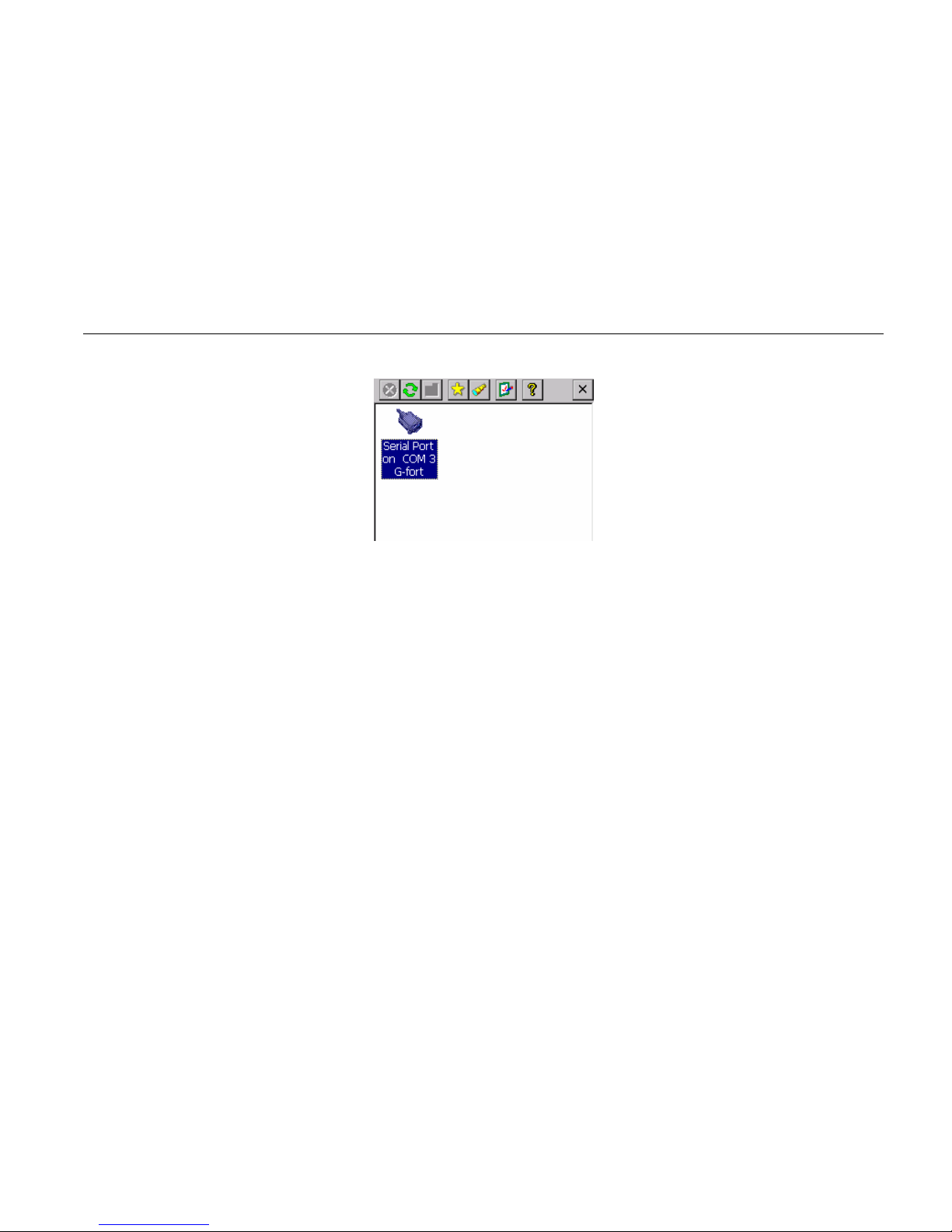
59
To establish a connection from the shortcut, double-click on the icon or select
"Connect" in the contextual menu. Once the connection is established (even if the
connection is not successfully established), the display is switched to the services list
associated to device linked to the shortcut. The connection status of the service
(connected or not) is displayed not only on the service icon but also on the associated
shortcut icon. However, disconnection can only be performed from the service
contextual menu.
Page 72
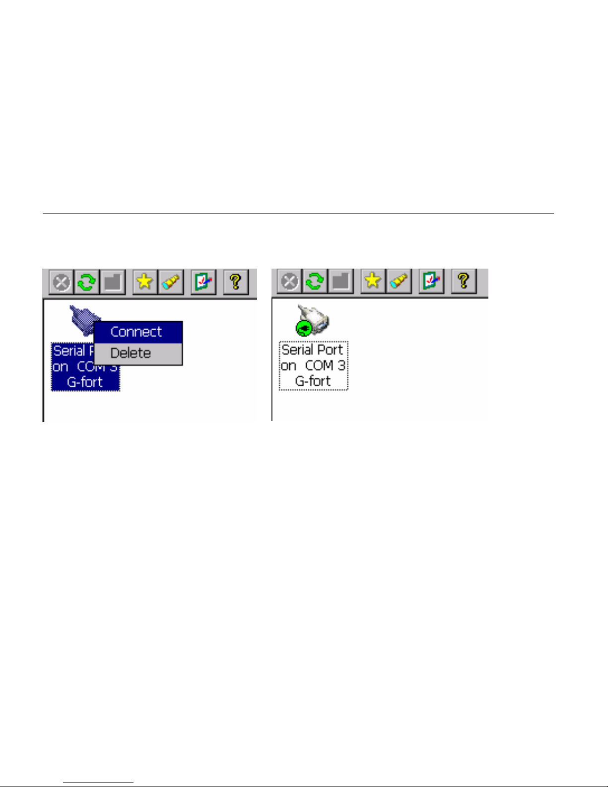
60
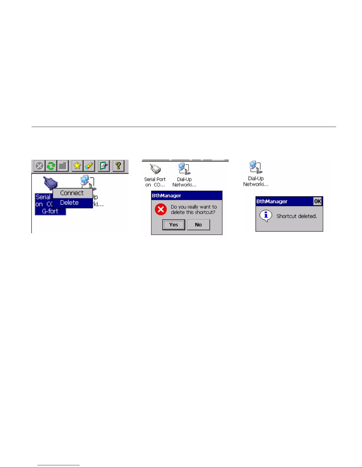
Shortcuts can be deleted by using the "Delete" item of the contextual menu. The user
must confirm the deletion.
Page 73
61
The content of the shortcut list is saved between executions of the Manager.
Page 74
62
Stop the Bluetooth Manager
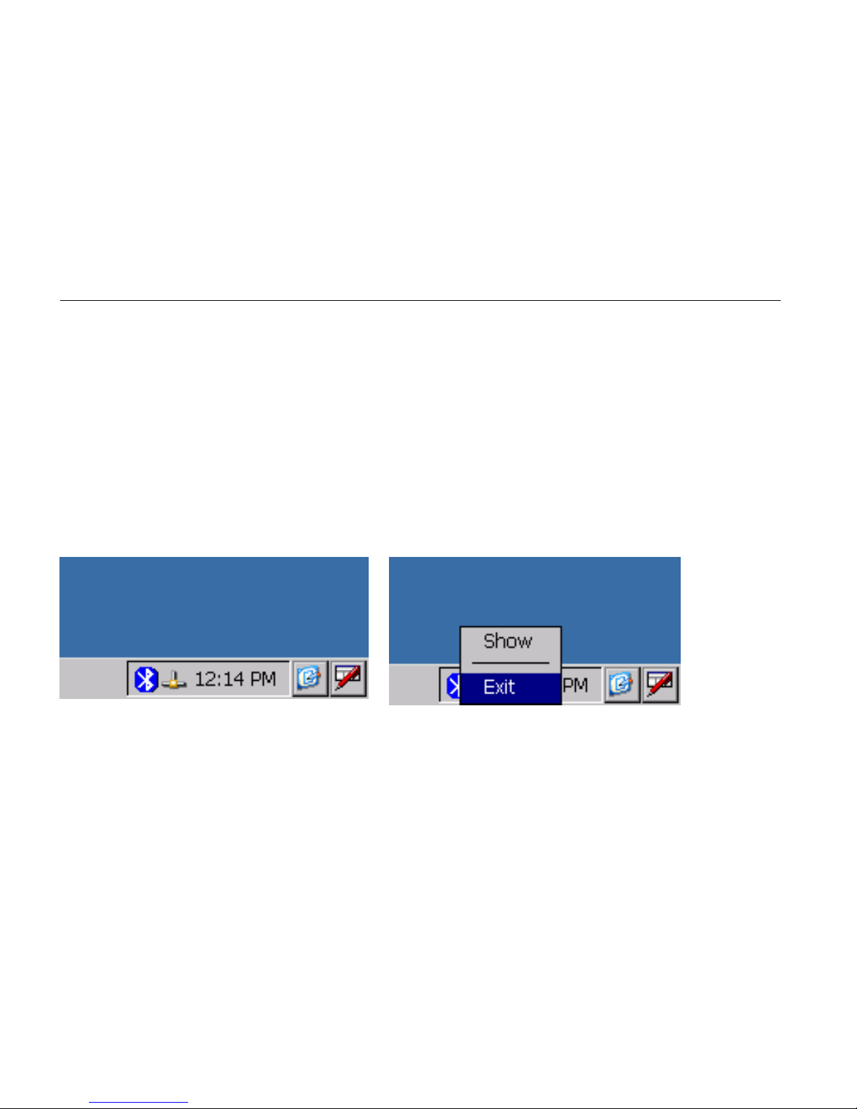
When the BlueTooth Manager window is closed (by the close button X), the
application is still running in the background. To display or stop it, click on the
BlueTooth icon on the Windows bar and select: “Show” or “Exit” . You can also
display it by starting again the application
Page 75

63
SPECIFICATIONS
CPU
Intel Bulverde PXA270
CPU speed 624MHz
Memory
RAM 128MB
ROM 128MB
Display
Type: 4” Active TFT Transflective Color LCD
Resolution: 480 x 640 pixels
Color: 64K
Backlight: LED
Touch Screen
Type: Resistive
Page 76

64
Interface: Serial
I/O ports
USB 2.0 port
USB client port
Serial port
Audio ports (Microphone/Earphone)
PCMCIA slot (type II x 1)
SD slot
System Unit Dimensions and Weight
Width: 90mm (W 3.5”)
Depth: 150mm (H 5.9”)
Height: 33mm (D 1.3”)
Weight: 450g (15 oz.)
AC Adapter
Voltage: AC 100~240 V
Page 77

65
Frequency: 50/60 Hz
Output Voltage: DC 12V 3.75A
Maximum Power: 45 Watts
Dimension: 108mm (4.2” W) x 56mm (2.2” D) x 34mm (1.3” H)
Weight: 270 g (9.5 oz.)
Battery
Type: Lithium Ion
Capacity: 3.7V 3900mAH
Dimension: 71mm (W 2.8”) x 64mm (D 2.5”) x 12.3mm (H 0.5”)
Weight: 108 g (3.8 oz.)
Page 78

66
Materials and Recycling
Materials of the computer are as follows:
Cabinet: Aluminum alloy ADC-12 or A380,
Magnesium alloy AZ91D,
UL grade PC+ABS GE C6200 or TN-3813BW
Bracket: Aluminum 5052
Steel with Nickel plating
Stainless Steel S304
Cushion pad: Nature rubber
PCB: FR-4, UL 94V0
Battery: Rechargeable Lithium Ion
Packing: Carton: Unbleached paper
User's Guide: Recycled/Recyclable paper
Please recycle the parts according to local regulations.
Page 79

67
Environmental Ratings
Temperature: DA05I:
0ºC ~ 45ºC (32ºF ~ 113ºF) operating
-20ºC ~ 60ºC (-4ºF ~ 140ºF) storage
DA05M:
-20ºC ~ 50ºC (-4ºF ~ 140ºF) operating
-40ºC ~ 70ºC (-40ºF ~ 158ºF) storage
Humidity: 5 ~ 95% Non-condensing operating
95% maximum storage
Altitude: 0 ~ 12,180 meters (0 ~ 40,000 feet) operating and storage
Page 80

68
MAINTENANCE / SERVICE
Cleaning
Always turn OFF the power, unplug the power cord and remove the battery before
cleaning.
The exterior of the system and display may be wiped with a clean, soft, and lint-free
cloth. If there is difficulty removing dirt, apply non-ammonia, non-alcohol based glass
cleaner to the cloth and wipe.
An air gun is recommended for cleaning water and dust. For salty water please wipe
with fresh water then blow-dry with an air gun. Close all caps tightly before water
cleaning.
Troubleshooting
Should the computer fail to function properly, you may try the following troubleshooting
steps: (Please backup your data before troubleshooting)
• Check AC adapter, battery, and the power source.
• Press hardware reset to re-boot the computer.
• Turn OFF the master switch for a while then turn ON and re-boot.
Page 81

69
• Remove the software suspected.
RMA Service
If troubleshooting is unsuccessful, please consult your dealer for service
If it is necessary to send in the computer for repairs, please follow the dealer’s instructio ns
for RMA# procedure.
Shipping instructions:
1. Use the original shipping container and packing materials, if possible.
2. If the original packing materials are not available, wrap the equipment with soft
material (e.g., PU/ PE form) then put the wrapped equipment into a hard
cardboard shipping box.
3. Include a sheet with the following information: (Note: please keep a copy for
your record)
• Name
• Address
• Unit serial number
• Place and date of purchase or the original invoice number
• Date of failure
Page 82

70
•
A DETAILED description of the problems you have encountered
• A list of the hard ware/software configuration, if applicable.
4. Clearly mark the outside of the shipping box with the RMA number. This will
facilitate faster processing and avoid faulty return.
5. Unless prior arrangements have been made, the customer is responsible for all
shipping costs. Unauthorized use of the company’s shipping accounts is not
permitted.
Recycled / Recycleable
Printed in Taiwan
 Loading...