

Durant-Eaton E4148794 Instruction Manual
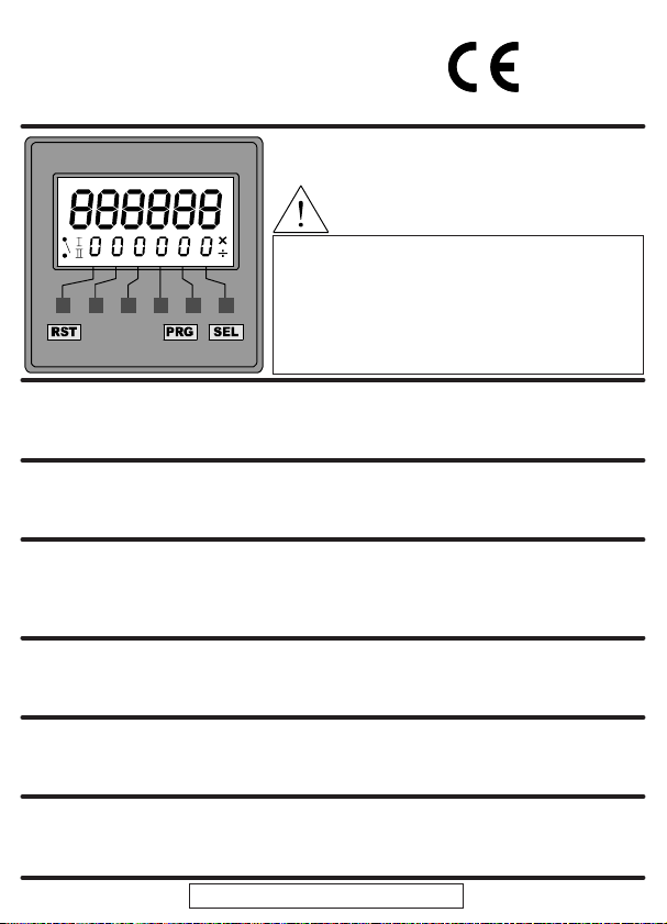
019512-01 Issue 1.0 04/03
6 digit programmable bi-directional counter relay, with
dual preset or batch mode operation, prescaling and
EEPROM data storage
6-Stelliger Bi-Direktionaler Zähler mit Supertwist-LCD
mit Einzel/Doppel- und Chargen Vorwahl, Skalierung
durch Vorteiler und EEPROM-Datenspeicherung
Compteur bidirectionnel à 6 chiffres, programmable,
avec 2 présélections ou 1 présélection et comptage de
lots, facteurs d'échelles et mémoire EEPROM
Relé contador bidireccional programable de 6 dígitos,
con modos de operación de doble preselección o de
lotes, pre-escala y almacenado de datos en EEPROM.
Contatore a relè a 6 cifre bidirezionale programmabile,
con funzionamento in doppia modalità preimpostata o
batch, prescala e memorizzazione dati nella EEPROM
Diagrams, Abbildungen, Diagrammes,
Diagramas, Diagrammi
English
Page 2
Deutsch
Seite 8
Français
Page 14
Español
Página 20
Italiano
Pagina 26
Page 35
Seite 35
Pagina 35
WARNING:Read page 32 first.
ACHTUNG:Lesen Sie zuerst Seite 32!
RECOMMANDATION IMPORTANTE:
Reportez-vous tout d'abord à la page 33
ATENCIÓN:Primero lea la página 33
ATTENZIONE: Leggere prima la pagina 34.
Durant
®
Durant
®
E4148794
Specification
Display
Black on green STN LCD, with yellow/green LED
backlight.
Program Storage
Erase/write cycles:1,000,000
Life: 40 years min
Count Range
-99999 to 999999
Count Pre-scaler
Multiplier 0.00250 to 9.99999
Divider 1 to 99999
External Reset response time
Max 2ms
Count Inputs
High Speed: 10kHz max (electronic)
(Dividing prescaler: 7kHz max)
Duty cycle: 60:40 max
Low Speed: 30Hz max (contact closure)
Relay Contacts
5A resistive load 100,000 operations
2A resistive load 1,000,000 operations
Reaction time: <20ms.
P1 Relay: UL Ratings
AC 250V max, DC 125V max
250VAC 1/6 HP
30VDC 5A
P1 Relay: General ratings
AC 1250VA max 300V AC
250Vac (cosø =1): 5A
250Vac (cosø =0.4): 3A
DC 150W max 220V DC
30Vdc: 5A
P2 Relay: UL Ratings
AC 250V max, DC 125V max
250VAC 1/6 HP
30VDC 5A
P2 Relay: General ratings
AC 2000VA max 300V AC
250Vac (cosø =1): 8A
250Vac (cosø =0.4): 5A
DC 150W max 220V DC
30Vdc: 5A
Supply (see Connections)
94 to 240V AC ± 10% 50/60Hz
VA Rating 4VA
or 12 to 24VDC ± 10%
typical current 100mA DC (max)
Installation Category (IEC 664)
Overvoltage category II
(Pollution degree 2)
Operating temperature
-10°C to +60°C
Storage temperature
-20°C to +70°C
Environmental protection
IP65 (panel mounting) using the sealing gasket
supplied (without Screw-fixed bezel). If the seal is
removed, it must be replaced with a new one.
See page 39 for cut-out dimensions
Altitude
Up to 2000m
Relative Humidity
80% max up to 31°C, decreasing to 50% max at
40°C
The front panel buttons are used to program the counter and to display and set the P1
and P2 presets. All the buttons can be disabled by the Keyboard Inhibit input. (see
Programming, page 6).
Auto Reset (see and on page 35)
When Auto Reset is on, the counter will be automatically reset as follows:
In Reset to Zero mode, the counter will reset to zero when P1 is reached.
In Reset to P1 mode, the counter will reset to P1 when zero is reached.
Front Panel Reset and External Reset (RST / Ext. Reset)
A Reset can be caused by pressing the RST button or by applying a signal to the
External Reset input. Any active relay will be returned to its normal condition.
If the operation of the External Reset is safety critical, it is recommended that the External
Reset signal is derived from an independent power supply which will remain stable if the
E4148794’s supply is interrupted.
P1 and P2 Presets
The minimum value possible for P1 and P2 is 000001,except in Dual Preset
mode, when P2 can be set to zero. P1 and P2 must be greater than any
31
2
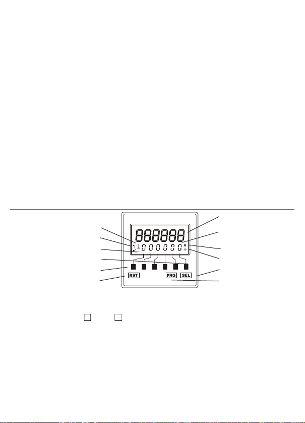
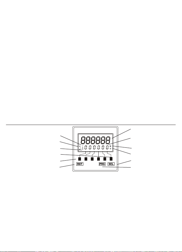
The Front Panel
Durant
®
Count
P1 or P2 or
Batch Total
Digit 1
Multiplying Prescaler
Dividing Prescaler
Select
Program
Reset
P1 Relay state
P2 Relay operated
P1 Relay operated
Digit 6
multiplying prescaler value, or the unit may not operate correctly.
The P1 preset can be set at any time.
In Reset to Zero mode, the change will be accepted immediately.
In Reset to P1 mode, the change will not be accepted until after a Reset.
The P2 preset can be set as shown below.
The change will be accepted immediately.
Count Modes (see page 35)
The diagrams show how the P1 and P2 Relays are controlled by the Count, by Batch
Total and by Reset.
The diagrams show how the Count is reset to zero or P1 by Auto Reset. In all modes, the
Count can be reset at any time by a RST/Ext. Reset.
The counter can count up to 999999, and or down to -99999. Beyond these limits, the
counter will continue to count internally, but the display will flash 999999 or -99999 until
either the count returns to below the limit, or the counter is reset by RST/Ext. Reset.
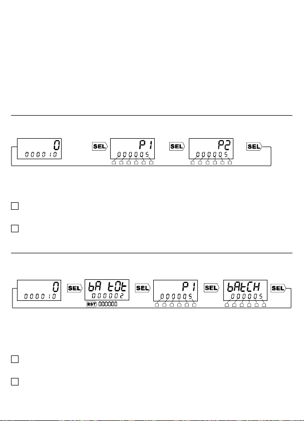
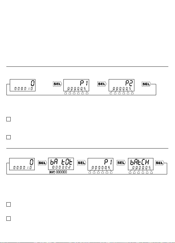
Dual Preset Mode
In Dual Preset mode, P1 and P2 are used independently to control the operation of the
counter and the relays.
Press SEL, then use the Digit buttons to change P1. The display will flash. Press SEL
again to accept the new P1 value, then use the Digit buttons to change P2. Press SEL
again to accept the new P2 value. If SEL is not pressed within 30 seconds of the last
change to either P1 and P2, they will revert to their original values.
Dual Preset with Auto Reset on
Note: P1 Relay cannot be set to Latched.
Note: If P2 Relay is set to Latched, it will return to normal at the same time as P1 Relay.
Dual Preset with Auto Reset off
Note: If P1 or P2 Relays are set to Latched, they will return to normal at RST/Ext. Reset.
Batch Mode
In Batch mode, P1 and P2 are used in combination to control the operation of the counter
and the relays.
Set P1 and P2, as shown above for Dual Preset mode.
When the Batch Total is displayed, the RST button can be used to reset it to zero.
Note: P2 relay cannot be set to Pulsed.
Note: The P2 Relay operates when the Batch Total reaches P2. It will return to normal
when the Batch Total is reset to zero.
Batch Mode with Auto Reset on
Note: P1 relay cannot be set to Latched.
Note: The Batch Total increments at Auto Reset.
Batch Mode with Auto Reset off
Note: If P1 is set to Latched, it will return to normal at RST/Ext. Reset.
Note: The Batch Total increments at the first RST/Ext. Reset after P1 has been reached.
4
3
2
1
3
P1
P2
P1
Count
P2
P1
P1
Batch
Total
Connections WARNING: This counter must not be wired the same as the
Durant E4148792.
Inputs A and B in Unidirectional mode
In the two Unidirectional modes, the count is incremented or decremented by input A,
whilst the direction is dependent on input B.
In Unidirectional High mode, both inputs are high speed inputs, suitable only for
electronic signal sources, eg. transistors, proximity switches, encoders.
In Unidirectional Low mode, both inputs are low speed inputs (30Hz max), suitable
for contact closure sources, eg. microswitches, relays, pushbuttons. Any contact
noise is removed by filtering. They can also be used for electronic signal sources.
Inputs A and B in Quadrature mode
In Quadrature mode, the count is incremented or decremented depending on the phase
difference between input Aand input B.
In this mode, both inputs are high speed inputs, suitable only for electronic signal
sources, eg. transistors, proximity switches, encoders.
Input K (Keyboard Inhibit) and Input R (Reset)
Both inputs are low speed inputs as described above.
Cables
Maximum wire size the connector can accept is:
2.5mm
2
cross sectional area; 1.8mm diameter. (equivalent 13 AWG solid wire)
Any signal cables connected to this device must not exceed 30 metres in length.
If signal cables are installed that are routed outside the building, it will be
necessary to install additional surge protection devices.
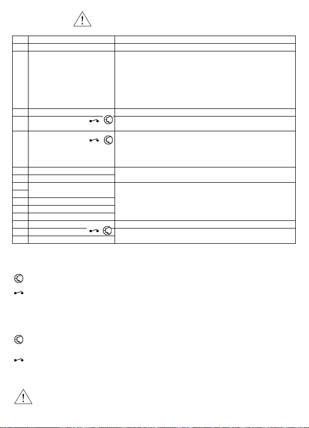
Pin
Description Range
1 Auxilliary DC Supply -ve 0V - See pin 2, below
2 Auxilliary DC Supply +ve Power Supply (see pages 37 & 38)
The counte r can be powered by AC mains, in which
case pins 1 and 2 provide an Auxilliary supply
(+12V DC +20% -0%, 75mA max recommended) which
can be used to power sensors if required.
Alternatively, the counter can be powered by an
external DC source (12-24V DC ±10%, 100mA),
connected to pins 1 and 2.
3 4/5 Common See Input Polarity, page 5
4 External Reset Input
(Input R)
Opto-isolated, 12-240 V ±10% DC or 50/60Hz AC
See Specification, pa ge 2
5 Keyboard Disable Input
(Input K)
Opto-isolated, 12-240 V ±10% DC or 50/60Hz AC
See Specification, pa ge 2
This input can be used to disable the fro nt pa nel
buttons, but only if configured by the Inhibit option.
See Programming, page 6
6 Neutral
7Live
94 to 240VAC ±10% 50/60 Hz
8
9
P2 Relay contacts
10 P1A contact
11 P1 Common contact
12 P1B contact
Isolated relay contacts
50/60Hz 300V AC max, 220V DC max
See Specification, pa ge 2
See Relays, page 5
13 14/15 Common See Input Polarity, page 5
14 Input B
15 Input A
5-30 VDC See Specification, page 2
4
Relays (see page 38)
The P2 relay can be programmed to be normally-open or normally-closed. In the case of
the P1 relay, contact P1Acan be programmed to be normally-open or normally-closed.
P1B will always be the opposite of P1A.
The relays can be programmed independently to operate in pulsed or latched mode. In
pulsed mode (P1 relay: Auto Reset Off only) the relay will operate for a length of time set
by the program. In latched mode the relay will operate, and stay in that condition until
reset.
The relays can be programmed to revert to a known safe state in the event of a power
failure or on entering program mode. The alternatives are:
Current - the contacts will remain in the same state as before the event;
Reset - the contacts will revert to their normal, unoperated state;
5
15
A
R
B
K
A
K
R
B
1
1
14
5
4
3
4
5
14
15
13
13 3
–V–V
–V
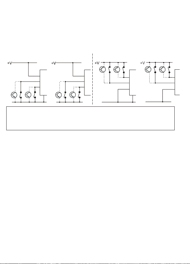
Count Direction (see page 36)
In all modes, count direction is dependent on Reset mode (see Programming) and
Sink/Source wiring, as shown in the diagrams. The count direction and the edges that
trigger the count are shown by the arrows.
For unidirectional mode, the count directions obtained with input B open-circuit are
marked *.
Note:
The count direction must not change in less than 25 µs, or the unit may not operate
correctly.
Sink Inputs (NPN)
Source Inputs (PNP)
Input Polarity (see page 37)
Inputs Aand B (pins 15 and 14) can be sink or source dc inputs, depending on the way
they are wired, with respect to their Common input (pin 13), as shown in the examples
below, and on pages 37 and 38. Pin 1 must always be connected as shown.
The opto-isolated inputs K and R (pins 5 and 4) can be sink or source ac or dc inputs,
depending on the way they are wired, with respect to their Common input (pin 3), as
shown in the examples below and on pages 37 and 38.
Only K and R are isolated from the supply pins.
Note: Common Pins 3 and 13
These pins must always be correctly connected for their inputs to work.
For dc signals, to +V or -V, as shown in the examples above and on page 37.
For ac signals (5/4/3 only), as shown in example 4 on page 37.
6
If the Prescaler or the Reset Mode or the Batch Mode are changed, the new
configuration will not be fully effective until after exit from Program mode, AND THEN
AFTER a Reset.
Decimal Point
The decimal point can be in one of three positions, or off.
Prescaling
A multiplying or dividing factor can be used. If a multiplying prescaler of n is used, the
counter will count: 0, n, 2n, 3n etc. If a dividing prescaler of n is used, the counter will
increment or decrement on every nth input pulse.
Input Mode
See Input Modes.
Batch Mode
See Count Modes.
Reset Mode
See Auto Reset and Count Modes
Inhibit
See Front Panel.
Auto Reset
See Auto Reset and Count Modes
P1 and P2 Relays
See Relays
* Auto Reset On and P1 Relay Latched cannot be set together.
** In Batch mode, P2 Relay cannot be set to Pulsed.
LCD Backlight:
can be on, off, or turn on for 30 seconds when a button is pressed.
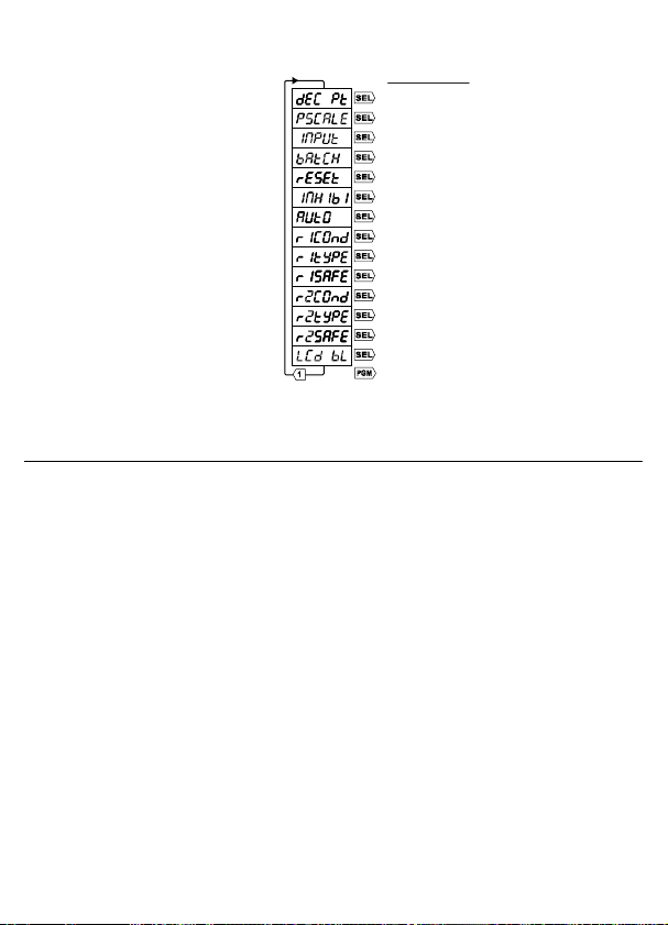
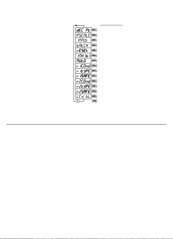
Programming
• Press and hold PGM for 3 seconds to enter Programming mode.
• Press Digit 1 to cycle through the
menus, or PGM to exit
Programming mode.
• Press SEL to select a menu, then
Digit 1 to cycle through the
options.
• Press SEL to select an option, or
PGM to exit the menu without
change.
• Press the Digit buttons to adjust a
numerical setting, eg. pulse time.
• Press SEL to accept the setting,
or PGM to exit the setting without
change.
• Press PGM once or twice to exit
Programming mode.
Main menu
Decimal Point menu
Prescaling menu
Input Mode menu
Batch Mode menu
Reset Mode menu
Inhibit menu
Auto Reset menu
P1 Relay Condition menu
P1 Relay Type menu
P1 Relay Safe State menu
P2 Relay Condition menu
P2 Relay Type menu
P2 Relay Safe State menu
LCD Backlight menu
Exit Programming mode
7
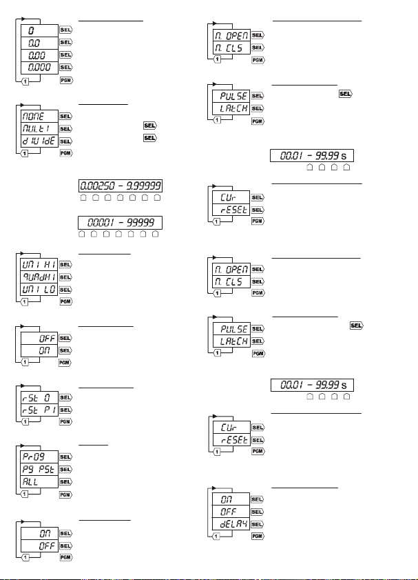
Decimal Point
No Decimal point
1 Decimal place
2 Decimal places
3 Decimal places
Main menu
Prescaling
No prescaling
Multiply -------Divide ---------Main menu
P1 Relay Condition
P1A Normally open
P1A Normally closed
Main menu
P2 Relay Condition
Normally open
Normally closed
Main menu
P1 Relay Type
Pulsed ---------Latched*
Main menu
P2 Relay Type
Pulsed ** ---------Latched
Main menu
P1 Relay Safe State
Current state
Normal state
Main menu
P2 Relay Safe State
Current state
Normal state
Main menu
LCD Backlight
On
Off
Delay
Main menu
Input Mode
Unidirectional high speed
Quadrature high speed
Unidirectional low speed
Main menu
Batch Mode
Batch Mode off
Batch Mode on **
Main menu
Reset Mode
Reset to Zero
Reset to P1
Main menu
Inhibit
Programming
Programming and Presets
All buttons
Main menu
Auto Reset
Auto Reset on *
Auto Reset off
Main menu
Multiply
Divide
Pulsed
Pulsed
Die beiden Tasten auf der Frontblende dienen zum Programmieren des Zählers sowie zum
Anzeigen und Einstellen der Vorwahlwerte P1 und P2. Alle Tasten können über den
Tastensperren-Eingang deaktiviert werden (siehe „Programmierung" auf S. 12).
Automatisches Rücksetzen (siehe 1 und 3 auf S. 35)
Bei eingeschaltetem automatischen Rücksetzen wird der Zähler wie folgt automatisch zurückgesetzt:
Im Modus „Auf Null zurücksetzen" wird der Zähler auf „0" gesetzt, wenn P1 erreicht wird.
Im Modus „Auf P1 zurücksetzen" wird der Zähler auf P1 zurückgesetzt, wenn Null erreicht wird.
Rücksetzen über Frontblende und externes Rücksetzen (RST/Ext. Reset)
Der Zähler kann mit der Taste RST oder durch Anlegen eines Signals, an den Eingang zum
externen Rücksetzen, zurückgesetzt werden. Wenn ein Relais aktiv ist, wird es dadurch wieder
in den Normalzustand versetzt.
Bei sicherheitskritischem Betrieb mit externem Rücksetzen empfiehlt es sich, das externe
Rücksetzsignal von einer unabhängigen Stromversorgung abzuleiten, die auch bei einer
Unterbrechung der Versorgung des E4148794 stabil bleibt.
Voreinstellungen P1 und P2
Der kleinstmögliche Wert für P1 und P2 ist 000001 (ausser im
Dualvoreinstellungsmodus, wenn P2 auf Null gesetzt werden kann). P1 und P2 müssen
8
Frontblende
Durant
®
Zähler
Chargensumme
P1 oder P2
Wahltaste 1
Vorteiler-Multiplikator
Vorteiler-Divisor
Auswahl
Programmieren
Rücksetzung
Zustand Relais P1
Relais P2 angesprochen
Relais P1 angesprochen
Wahltaste 6
Spezifikation
Anzeige
STN-LCD, schwarz auf grün, mit gelb-grüner
LED-Hintergrundbeleuchtung.
Programmspeicher
Lösch-/Schreibzyklen:1.000.000
Datenerhalt Mindestens 40 Jahre
Zählbereich
-99999 bis 999999
Vorteiler für Zähler
Multiplikator 0,00250 bis 9,99999
Divisor 1 bis 99999
Reaktionszeit bei externem Rücksetzen
Max. 2ms
Zähleingänge
Hochgeschwindigkeit: 10kHz max. (elektronisch-TTL)
(Vorteiler 7kHz max)
Arbeitszyklus: Max. 60:40
Langsamer Zähleingang: 30Hz max.
(mechanischer Kontakt)
Relaiskontakte
100.000 Schaltvorgänge bei 5AWiderstandsbelastung
1.000.000 bei 2AWiderstandsbelastung
Reaktionszeit: <20ms.
Relais P1: UL-Kenndaten
AC 250V max., DC 125V max.
250VAC 1/6 PS
30VDC 5A
Relais P1: Allgemeine Kenndaten
AC 1250VA max. 300V AC
250Vac (cosø = 1): 5A
250Vac (cosø = 0,4): 3A
DC 150W max. 220V DC
30Vdc: 5A
Relais P2: UL-Kenndaten
AC 250V max., DC 125V max.
250VAC 1/6 PS
30VDC 5A
Relais P2: Allgemeine Kenndaten
AC 2000VA max. 300V AC
250Vac (cosø = 1): 8A
250Vac (cosø = 0,4): 5A
DC 150W max. 220V DC
30Vdc: 5A
Versorgung (siehe „Anschlüsse")
94V bis 240V AC ± 10% 50/60Hz
VA-Nennleistung 4VA
oder 12V bis 24VDC ± 10%
typischer Strom 100mA DC (max.)
Installationskategorie (IEC 664)
Überspannungskategorie II
(Verunreinigungsgrad 2)
Betriebstemperatur
-10°C bis +60°C
Lagerungstemperatur
-20°C bis +70°C
Schutzart
IP65 (Tafeleinbau) mit mitgelieferter Dichtung (ohne
Montageplatte). Wenn die Dichtung entfernt wird,
muss sie durch eine neue ersetzt werden.
Abmessungen der Aussparung siehe S. 39.
Betriebshöhe
Bis 2000m
Relative Luftfeuchtigkeit
80% max. bis 31°C, abnehmend um max. 50%
bis 40°C
jeweils grösser sein als der Wert des Vorteiler-Multiplikators, da das Gerät sonst nicht
ordnungsgemäss funktioniert. Die Voreinstellung P1 kann jederzeit eingestellt werden.
Im Modus „Auf Null zurücksetzen" wird die Änderung sofort übernommen.
Im Modus „Auf P1 zurücksetzen" wird die Änderung erst nach einem Rücksetzen übernommen.
Die Voreinstellung P2 kann wie nachstehend beschrieben eingestellt werden.
Die Änderung wird sofort übernommen.
Zählermodi (siehe S. 35)
Die Abbildungen zeigen, wie die Relais P1 und P2 durch den Zähler, die Chargensumme und
Rücksetzen gesteuert werden. Die Abbildungen zeigen, wie der Zähler durch automatisches
Rücksetzen auf Null oder P1 zurückgesetzt wird. Der Zähler kann in allen Modi jederzeit durch
RST/Ext. Reset zurückgesetzt werden.
Der Zähler kann bis auf 999999 hoch- oder bis auf -99999 herunterzählen. Ausserhalb dieses
Bereichs wird die Zählung intern fortgesetzt; in der Anzeige blinkt allerdings der Zählerstand
999999 bzw. -99999, bis der Zähler entweder wieder in den Zählbereich eintritt oder durch
RST/Ext. Reset zurückgesetzt wird.
Zweifach-Voreinstellmodus
Im Zweifach-Voreinstellungsmodus dienen P1 und P2 unabhängig voneinander zur Steuerung
des Zählers und der Relais.
Drücken Sie SEL, und ändern Sie anschliessend P1 mit Hilfe der Zifferntasten. Daraufhin blinkt die
Anzeige. Drücken Sie nochmals SEL, um den neuen Wert für P1 zu übernehmen, und ändern Sie
anschliessend P2 mit Hilfe der Zifferntasten. Drücken Sie nochmals SEL, um den neuen Wert für P2
zu übernehmen. Wenn SEL nicht innerhalb von 30 Sekunden nach der letzten Änderung von P1 oder
P2 gedrückt wird, gelten wieder die ursprünglichen Werte.
Zweifache Voreinstellung mit aktiviertem automatischen Rücksetzen
Hinweis: Das Relais P1 kann nicht auf „arretiert" gesetzt werden.
Hinweis: Wenn das P2-Relais auf "Verriegelt" steht, schaltet es zur gleichen Zeit wie das P1-
Relais wieder in den Normalbetrieb.
Zweifache Voreinstellung mit deaktiviertem automatischem Rücksetzen
Hinweis: Wenn das Relais P1 oder P2 auf „arretiert" gesetzt ist, kehrt das jeweilige Relais bei
einer automatischen Rücksetzung oder RST/Ext. Reset wieder in den Normalzustand zurück.
Chargenmodus
Im Chargenmodus dienen P1 und P2 gemeinsam zur Steuerung des Betriebs des Zählers und der Relais.
Stellen Sie P1 und P2 entsprechend der Abbildung für den Zweifach-Voreinstellmodus ein.
Wenn die Chargensumme angezeigt wird, kann mit der Zifferntaste RST Rücksetzen auf Null
Durchgeführt werden.
Hinweis: Das Relais P2 kann nicht auf „gepulst" gesetzt werden.
Hinweis: Das Relais P2 spricht an, wenn die Chargensumme P2 erreicht. Kehrt es beim
Zurücksetzen der Chargensumme auf Null in den Normalzustand zurück.
Chargenmodus mit aktiviertem automatischen Rücksetzen
Hinweis: Das Relais P1 kann nicht auf „arretiert" gesetzt werden.
Hinweis: Die Chargensumme wird bei automatischem Rücksetzen inkrementiert.
Chargenmodus mit deaktiviertem automatischem Rücksetzen
Hinweis: Wenn P1 auf „arretiert" gesetzt ist, kehrt es bei einer RST/Ext. Reset wieder in den
Normalzustand zurück.
Hinweis: Die Chargensumme wird bei der ersten RST/Ext. Reset nach Erreichen von
P1 inkrementiert.
4
3
2
1
9
P1
P2
P1
Zähler
P2
P1
P1
Chargensumme

Anschlüsse ACHTUNG: Dieser Zähler darf nicht auf die gleiche Weise
verdrahtet werden wie die Durant E4148792.
Eingänge A und B im unidirektionalen Modus
In den beiden unidirektionalen Modi wird der Zählerwert durch Eingang Aerhöht oder reduziert;
dabei bestimmt Eingang B die Zählrichtung.
Im Modus „Unidirektional hoch" fungieren beide Eingänge als Hochgeschwindigkeitseingänge, die
sich nur für elektronische Signalquellen wie Transistoren, Näherungsschalter, Kodierer usw. eignen.
Im Modus „Unidirektional niedrig" fungieren beide Eingänge als Niedergeschwindigkeitseingänge
(max. 30Hz), die sich für Schliesskontakte wie Mikroschalter, Relais, Drucktasten usw. eignen.
Kontaktprellen wird durch Dämpfung entfernt. Die Eingänge können in diesem Modus auch für
elektronische Signalquellen verwendet werden.
Eingänge A und B im Quadraturmodus
Im Quadraturmodus wird der Zählerwert entsprechend dem Phasenunterschied zwischen
Eingang Aund Eingang B erhöht oder reduziert.
In diesem Modus fungieren beide Eingänge als Hochgeschwindigkeitseingänge, die sich
nur für elektronische Signalquellen wie Transistoren, Näherungsschalter, Kodierer usw.
eignen.
Eingang K (Tastensperre) und Eingang R (Rücksetzen)
Beide Eingänge sind langsame Zähleingänge wie oben beschrieben.
Kabel
Maximaler Querschnitt an der Schraubklemme:
Querschnittsfläche 2,5mm²; Durchmesser 1,8mm (entspricht Volldraht 13 AWG)
Die Signalleitungen, die an dieses Gerät angeschlossen werden, dürfen eine
Gesamtlänge von 30m nicht überschreiten.
Werden Signalleitungen außerhalb von Gebäuden verlegt, müssen zusätzliche
Schutzmaßnahmen gegen Surge Störimpulse vorgesehen werden.
Pin
Beschreibung Bereich
1 DC-Zusatzversorgung -ve 0V - Siehe unten, Pin 2
2 DC-Zusatzversorgung + ve Stromversorgung (siehe S. 37 und 38) Der Zähler kann
aus dem Wechselstromnetz versorgt werden; in diesem
Fall dienen Pin 1 und 2 als Zusatzversorgung
(+12V DC +20% -0%, 75mA max. empfohlen), mit der
erforderlichenfalls Sensoren versorgt werden können.
Alternativ kann der Zähler du rch ei n e exte rne
Gleichstromquelle (+12 bis 24V DC ±10% , 100m A) mit
Anschluss an Pin 1 und 2 versorgt werden.
3
Gemeinsame Anschluss 4/5
Siehe Eingangspolarität, S. 11
4 Eingang für externes
Rücksetz en (Eingang R)
Optisch isoliert, 12-240 V ±10% DC oder 50/60Hz AC
Siehe Technische Daten, S. 8
5 Eingang für Tastensper re
(Eingang K)
Optisch isoliert, 12-240 V ±10% DC oder 50/60Hz AC
Siehe Technische Daten, S. 8
Mit diesem Eingang können die Tasten der Frontplatte
deaktiviert werden, aller ding s nur bei ent spr echender
Konfiguration über die Option Sperre.
Siehe Programmierung, S. 12
6 Neutral
7 Stromführend
94 bis 240VAC ±10% 50/60 Hz
8
9
P2 Kontakte
10 P1 Arbeitskontakt
11 P1 Kontakt für
gemeinsamen Anschluss
12 P1 Ruhekontakt
Isolierte Relaiskontak te
50/60Hz 300V AC max., 220V DC max.
Siehe Technische Daten, S. 8.
13
Gemeinsamer Anschluss 14/15
Siehe Eingangspolarität, S. 11
14 Eingang A
15 Eingang B
5-30 VDC Siehe Technische Daten, S. 8.
10

Relais (siehe S. 38)
Das Relais P2 kann so programmiert werden, dass es entweder normal offen oder normal
geschlossen ist. Im Falle des Relais P1 kann der Kontakt P1A so programmiert werden,
dass er entweder normal offen oder normal geschlossen ist. P1B ist immer
entgegengesetzt zu P1A eingestellt.
Die Relais können durch Programmierung unabhängig voneinander im gepulsten oder
arretierten Modus betrieben werden. Im gepulsten Modus (Relais P1: nur Automatisches
Rücksetzen aus) wird die Ansprechdauer des Relais durch das Programm vorgegeben.
Im arretierten Modus bleibt das Relais bis zum Rücksetzen im Ansprechzustand.
Die Relais können so programmiert werden, dass sie bei einem Stromausfall oder beim
Eintritt in den Programmmodus in einen bekannten sicheren Zustand zurückkehren.
Dabei gibt es die folgenden Möglichkeiten:
Aktuell - Die Kontakte bleiben im selben Zustand wie vor dem Vorfall.
Zurückgesetzt - Die Kontakte kehren in den normalen, nicht angesprochenen Zustand
zurück.
11
15
A
R
B
K
A
K
R
B
1
1
14
5
4
3
4
5
14
15
13
13 3
–V
–V–V
–V
Zählrichtung (siehe S. 36)
In allen Modi hängt die Zählrichtung vom Rücksetzungsmodus (siehe „Programmierung")
und von der Senken-/Quellenverdrahtung lt. Abbildungen ab. Die Zählrichtung und die
den Zähler auslösenden Flanken sind durch Pfeile gekennzeichnet.
Wenn sich Eingang B im unidirektionalen Modus im Leerlauf befindet, ergeben sich die
mit * markierten Zählrichtungen.
Hinweis: Die Pulsflanke darf nicht unter 25 µs absinken, da das Gerät sonst nicht
ordnungsgemäss funktioniert.
Sink-Eingänge (NPN)
Source-Eingänge (PNP)
Eingangspolarität (siehe S. 37)
Bei den Eingängen Aund B (Pin 15 und 14) kann es sich entsprechend der
Verdrahtungsart um Sink- oder Source-Gleichstromeingänge in bezug zur gemeinsamen
Anschluss (Pin 13) handeln (siehe Beispiele unten sowie auf S. 37 und 38). Stift 1 muss
immer, wie beschrieben, angeschlossen werden.
Bei den optisch isolierten Eingängen K und R (Pin 5 und 4) kann es sich entsprechend
der Verdrahtungsart um Sink- oder Source-Gleichstrom- oder -Wechselstromeingänge in
bezug zur gemeinsamen Anschluss (Pin 3) handeln (siehe Beispiele unten sowie auf S.
37 und 38).
Nur CT und R sind von der Versorgungsspannung isoliert.
Hinweis: Gemeinsame Anschluss, Pins 13 und 3
Diese Pins müssen immer ordnungsgemäss angeschlossen sein, damit die
entsprechenden Eingänge funktionieren.
Bei Gleichstromsignalen mit +V oder -V, wie in den Beispielen oben und auf S. 37
dargestellt.
Bei Wechselstromsignalen (nur 5/4/3) wie in Beispiel 4 auf S. 37 dargestellt.
Wenn der Vorteiler, der Rücksetzmodus oder der Chargenmodus geändert wird, gilt
die neue Konfiguration erst nach dem Verlassen des Programmiermodus UND der
Rücksetzung.
Dezimalpunkt
Für den Dezimalpunkt können drei verschiedene Positionen gewählt werden; ausserdem
kann der Dezimalpunkt ganz abgeschaltet werden.
Vorteiler
Als Vorteiler kann ein Multiplikator oder ein Divisor verwendet werden. Bei einem Vorteiler
- Multiplikator n verläuft die Zählung nach dem Schema 0, n, 2n, 3n usw. Bei einem
Vorteiler - Divisor n wird der Zähler bei jedem nten Eingangsimpuls erhöht oder reduziert.
Eingangsmodus
Siehe „Eingangsmodi".
Chargenmodus
Siehe „Zählermodi".
Rücksetzmodus
Siehe „Automatisches Rücksetzen" und „Zählermodi".
Sperre
Siehe „Frontseite".
Automatisches Rücksetzen
Siehe „Automatisches Rücksetzen" und „Zählermodi".
Relais P1 und P2
Siehe „Relais".
* „Automatisches Rücksetzen ein" und „Arretiert Relais P1" können nicht zusammen
eingestellt werden.
** Im Chargenmodus kann das Relais P2 nicht auf „gepulst" gesetzt werden.
LCD-Hintergrundbeleuchtung:
kann eingeschaltet, ausgeschaltet oder so eingestellt werden, dass sie nach dem
Betätigen einer Taste 30 Sekunden lang eingeschaltet bleibt.
12
Programmierung
• Halten Sie PGM drei Sekunden lang gedrückt, um in den Programmiermodus zu gelangen.
• Drücken Sie Zifferntaste 1, um die
Menüs zu durchlaufen, oder PGM,
um den Programmiermodus zu
verlassen.
• Drücken Sie SEL, um ein Menü
auszuwählen, und anschliessend
Zifferntaste 1, um die Optionen zu
durchlaufen.
• Drücken Sie SEL, um eine Option
auszuwählen, oder PGM, um das
Menü ohne Änderung zu
verlassen.
• Drücken Sie die Zifferntasten, und
eine numerische Einstellung, z. B.
die Impulszeit, anzupassen.
• Drücken Sie SEL, um die
Einstellung zu übernehmen, oder
PGM, um die Einstellung ohne
Änderung zu verlassen.
• Drücken Sie ein- oder zweimal PGM, um den Programmiermodus zu verlassen.
Hauptmenü
Menü: Dezimalpunkt
Menü: Vorteiler
Menü: Eingangsmodus
Menü: Chargenmodus
Menü: Rücksetzmodus
Menü: Sperre
Menü: Automatisches Rücksetzen
Menü: Zustand Relais 1
Menü: Typ Relais 1
Menü: Sicherer Zustand Relais 1
Menü: Zustand Relais 2
Menü: Typ Relais 2
Menü: Sicherer Zustand Relais 2
Menü: LCD-Hintergrundbeleuchtung
Menü: Programmierung beenden
 Loading...