

Durant-Eaton AMBASSADOR SERIES Instruction Manual
Durant
®
INSTALLATION AND OPERATION
MANUAL Number 57600-905-03
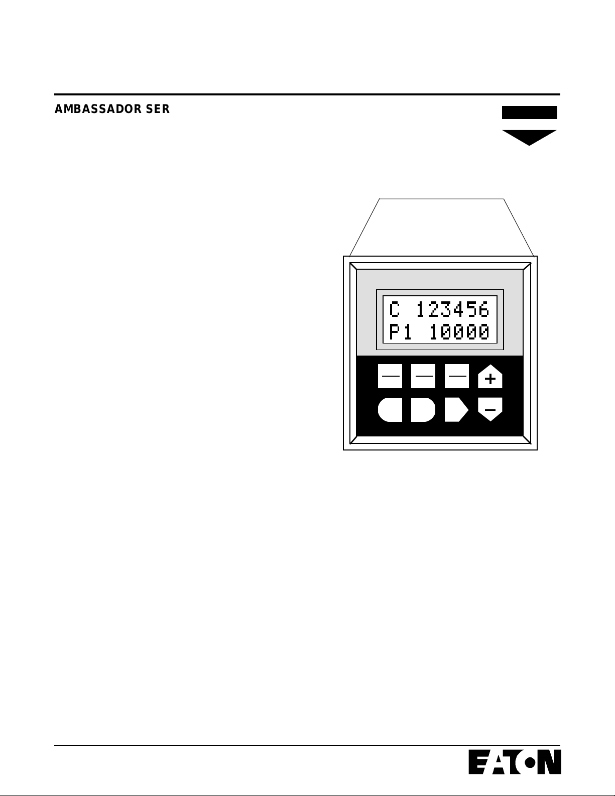
AMBASSADOR SERIES COUNT CONTROL
MODELS:
57600-405 (10-15 VDC)
57600-415 (10-15 VDC)
57600-465 (10-15 VDC)
57601-405 (115 VAC)
57601-415 (115 VAC)
57601-455 (115 VAC)
57601-465 (115 VAC)
57602-405 (230 VAC)
57602-415 (230 VAC)
57602-465 (230 VAC)
• Six Digit, Four Preset Main Counter
• Six Digit, Single Preset Batch Counter
• Red or Green Display
• Eight Digit Totalizer
• 1/Tau Rate Meter
• Four User-Configurable Control Inputs
• Two Output Relays
• Two Solid State Outputs
• RS-485 Serial Communications
• Feet/Inches Control, Red or Green Display
Durant
®
C 123456
P1 10000
RST
CLR
EXIT ENT SEL
RUN
PGM
PRNT
•
N A E D
ASSOCIATE
TABLE OF CONTENTS
1 Introduction
2 Block Diagram
3 Installation Wiring and Programming - Quick Start
10 Rear Terminal Description
12 Program Mode
22 Description of Program Options
26 Wiring
29 Calculating Scale Factors
30 Run Mode
33 Feet/Inches Control
34 Troubleshooting
36 Specifications
37 Parts / Accessories
38 Dimensions
Durant


INTRODUCTION
This manual describes the Ambassador 5760X-405 count
control, and is intended to be a guide in the installation and
operation of the control.
The control itself is like an electronic erector set, full of
counter and ratemeter "parts" which the user must "assemble". The majority of this manual is concerned with
installation, describing the parts of the counter, helping the
user determine the wiring and programming necessary to
"assemble" his counter into the tool he needs to do a specific
job, and documenting those choices. The operation section,
which describes the operator functions, follows in the section
Run Mode. The following description of the control and the
block diagram is recommended reading for those new with
this device. Those installers who are familiar with controls
and counter terminology are welcome to attack the Quick
Start section after examining the block diagram. The Quick
Start uses a logical inputs-to-outputs approach to decide how
to wire and program this control to do the job. Detailed
programming and wiring information follow the Quick Start
section, providing guidance to the first time installer.
MAIN COUNTER
The main counter is a six digit, bi-directional count register
designated by the letter C on the display. The user can assign
up to four presets to this counter. The main counter is the
workhorse of this control. Note its central location in the block
diagram and the number of "connections" to it. This register
increments and decrements from scaled count input pulses.
The "favored" count direction is up in reset to zero mode and
down in reset to final preset mode. The favored count
direction feature affects only the function of the count inputs,
and the direction of the totalizer count, and the preset
selected for the current preset display. The main count
display screen can be customized to identify what type of
units are being counted.
RATEMETER
The control uses the frequency of the count pulses at input A
to calculate rate. The rate scaler accommodates the "weight"
of each pulse and the time units in order to display rates such
as revolutions per minute, barrels per hour, etc. The ratemeter average and zero times are programmable. Two alarm
setpoints are assigned to the ratemeter. The rate display text
can be customized.
OUTPUTS
Two form C relay and two open collector NPN transistor
outputs are available. Each output is individually assignable
to rate or count. Count outputs can turn on or off at any
combination of eight preset and control events. These outputs can be timed or latched, and each has a programmable
on-delay timer. Rate based outputs turn on based upon
comparison to one of two rate alarm setpoints. Rate outputs
turn off after timeout (pulsed), external control signal (latched),
or when the rate crosses the setpoint back to the non-alarm
state (follows).
COUNT INPUTS
Count inputs A and B are DIP switch settable to accept
sinking or sourcing single ended DC or differential count
signals. Input A is used by the ratemeter. Inputs A and B are
programmable to affect the main counter and totalizer in eight
count modes and three count/control modes.
CONTROL INPUTS/RESET KEY
Four control inputs are available. These inputs are single
ended DC, sink only and are programmable to one of 14
functions. The reset key may be programmed to reset one,
all, or none of the count registers.
TOTALIZER
The totalizer is an eight digit, bi-directional count register that
counts in parallel with the main counter. The totalizer counts
up when the main counter counts in the favored count
direction, and down when the main counter counts in the nonfavored direction. The totalizer display can be customized to
show units of count. The totalizer does not have preset or
output capability.
BATCH COUNTER
The batch counter counts the number of "batches" of the
main counter, incrementing every time the main counter
autocycles or reaches the final preset. This register is six
digits and counts up only. The batch counter has one preset,
and always autocycles whenever it reaches the setpoint. The
batch count display can be customized to show units of
count.
RS 485 SERIAL COMMUNICATIONS
The control uses RS-485 serial communications in either
host mode: to respond to a host computer, or printer mode:
to dump selected values to a printer. The print transmission
is initiated by either the Print key or a control input. The
communication capability is described in a separate manual.
If you need information on the serial communications, contact the Literature Department at 1-800-540-9242.
FEET/INCHES CONTROL
Models 57601-415 (green display) and 57601-465 (red display) have a readout in feet and inches with a fixed decimal
point separating them. These models also have a floating
prewarn that adjusts itself to the final preset. See page 33 for
more details.
1
BLOCK DIAGRAM
A in
20
B in
19
15
16
17
18
RST
CLR
COUNT
LOGIC
R
CONTROL
INPUT
ASSIGNMENT
Total Count
Main Count
R
R, SC, BP1,
PU, DO
COUNT
SCALER
Scaled Total
Scaled Main
RATE METER
(Rate Scaling)
Not available
on feet/inches
control.
R
TOTALIZER
C
MAIN
C
COUNTER
BP1
SC
R
BATCH
C
COUNTER
R
P1
P2
P3
*P4
P1/PF
Pb
A1
A2
PU, DO
PU, DO
PU, DO
PU
PU
PU
DO
PU
DO
PU
DO
TRANSISTOR 1
OUTPUT LOGIC
TRANSISTOR 2
OUTPUT LOGIC
RELAY 1
OUTPUT
•
RELAY 2
OUTPUT
•
14
13
10
9
8
7
6
5
Key
R
SC
BP1
Reset
Stop Count
Bypass P1
Pick Up
PU
Drop Out
DU
Screw Terminal
C Count *P4 is the prewarn (Pw) on the
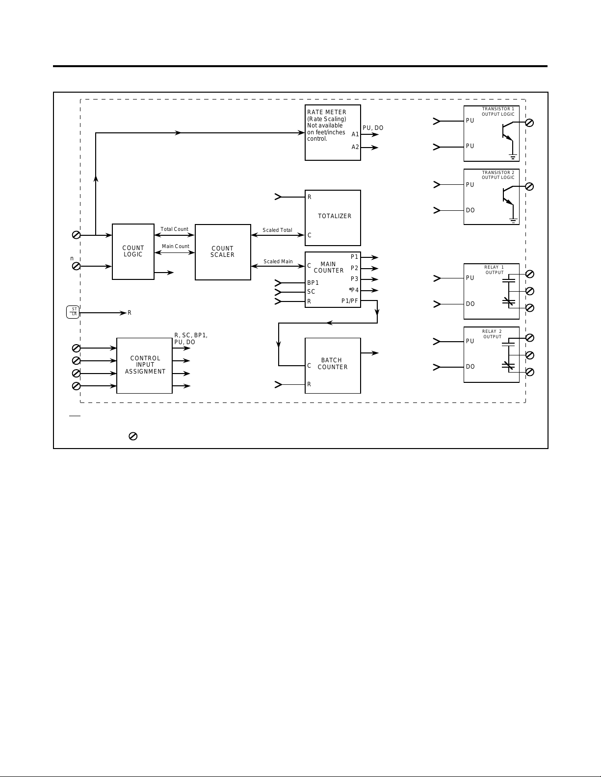
The block diagram shows the major internal "parts" of the
control. A general description of each block was given on the
previous page. The block diagram shows how the parts relate
to each other. The flow through the control is generally left to
right; inputs are designated by screw terminal number on the
left side of the block, and output terminals are shown on the
right side. In between, arrows lead from block to block from
the count inputs (19 and 20) to the count and rate registers.
The open ended arrows indicate "connections" that can be
made by programming.
Feet/Inches control.
The block diagram shows that the control will not respond to
the control inputs; (15, 16, 17, 18 and RST key) until they are
programmed to a specific function, and the outputs are also
oblivious to the count and rate registers until a programming
"connection" is made.
2
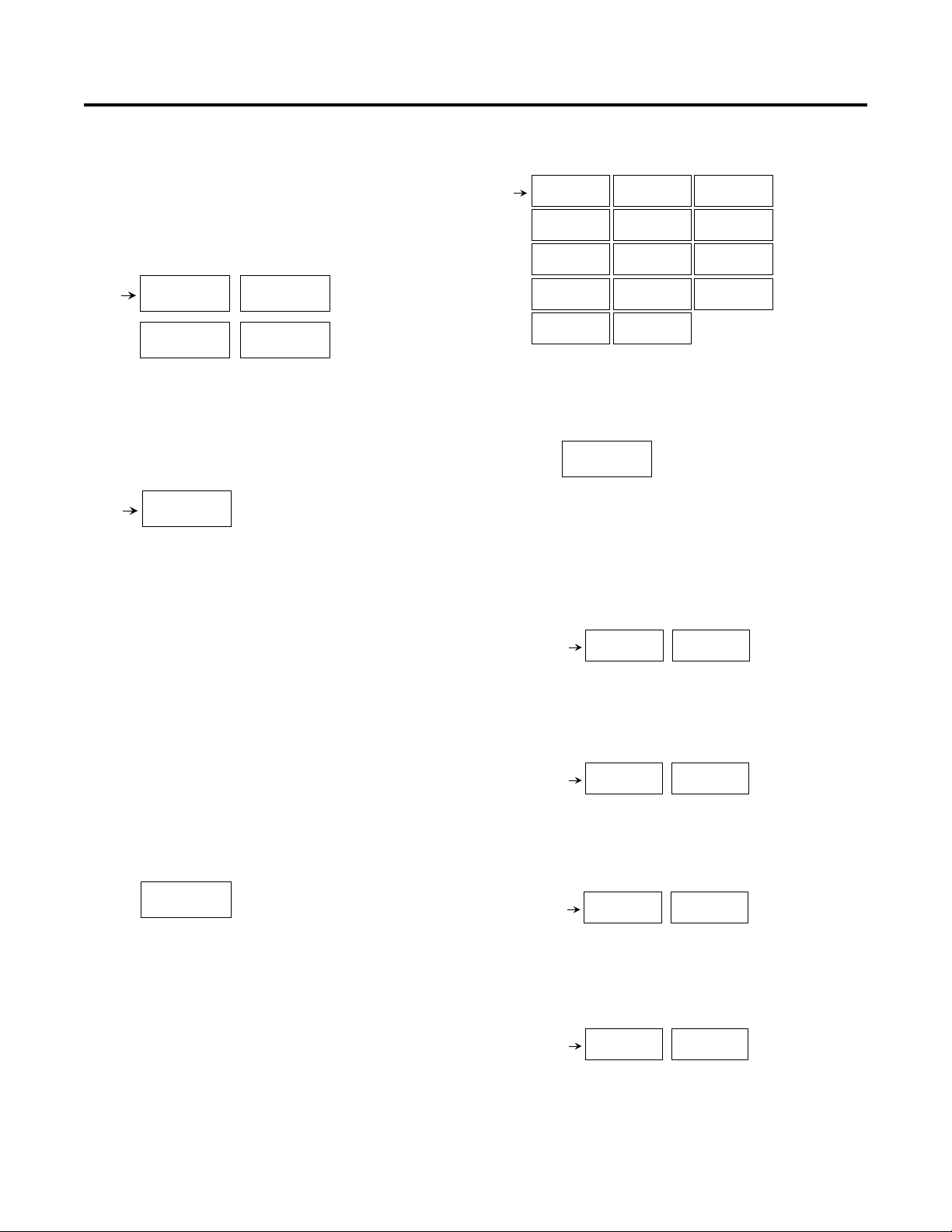
INSTALLATION WIRING AND PROGRAMMING - QUICK START
This section is a step-by-step process for determining program selections and I/O wiring. If the installer has a basic
knowledge of counter terminology and uses the block diagram for a reference, the configuration process should be
straightforward. Detailed descriptions of programming choices
are listed on pages 22 to 25. Detailed I/O wiring diagrams are
shown on pages 26 to 28. Instructions on calculating scale
factors are on page 29.
For each programming choice, a program item number is
listed. A selection space is provided to record the desired
selection. These numbers can be also recorded in the
programming menu chart on pages 14 to 21, in order to
D
document the application.
in the choice lists indicates
default setting.
I/O terminals used in the application can be labeled in the
space provided on page 10.
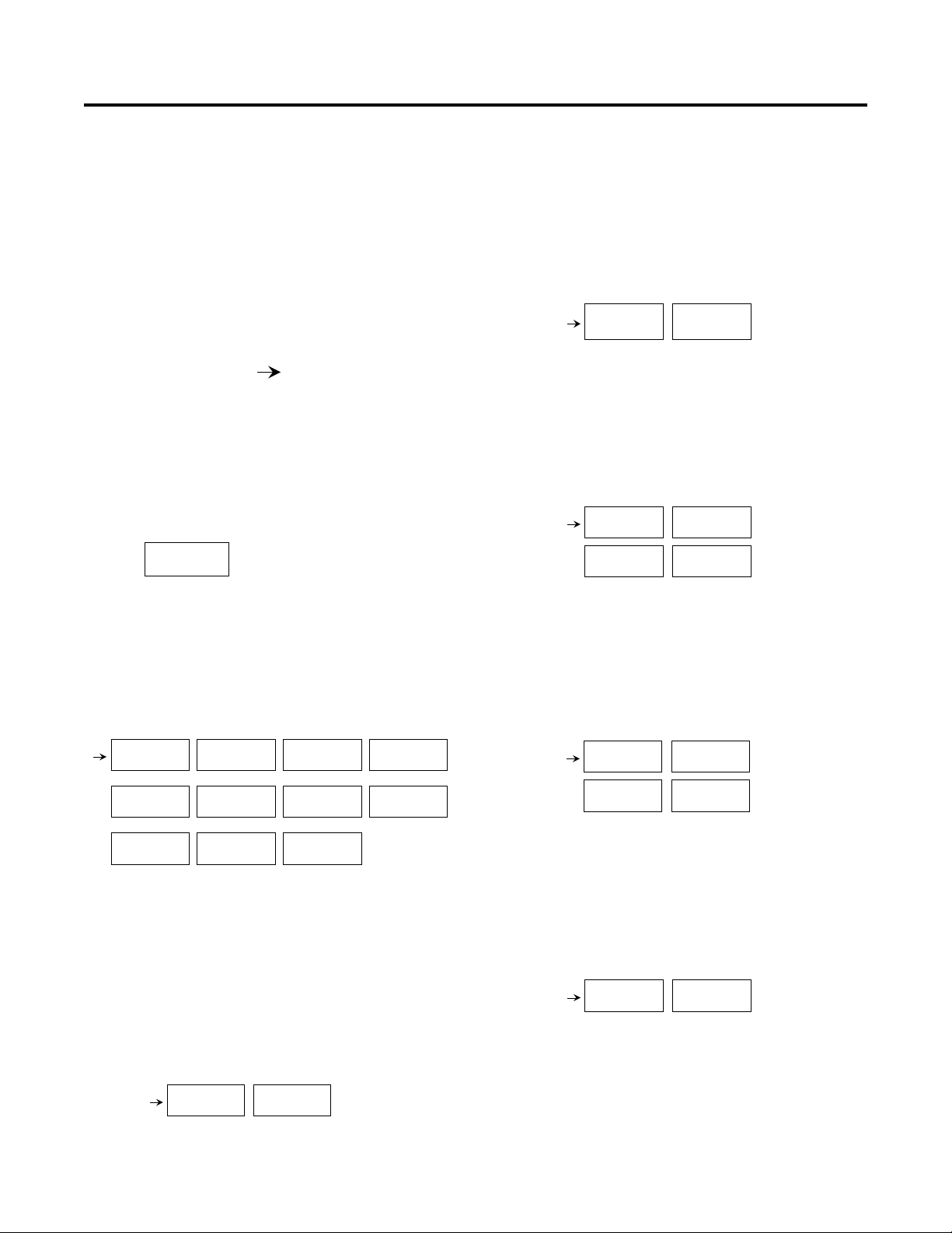
Phase I - The Vital Ingredients
1. Count Logic/Main Counter/Totalizer behavior determined
by:
PROGRAM
COUNT IN
A. Count Mode
Program Item 10 Selection __________
Consider: Type of count input sensor(s), main
counter and totalizer functions, and input B as a
count or control input.
Choices:
D
CNT + TOT
A-B
CNT + TOT
A, B DIR
CNT + TOT
QUAD X1
TOT A
CNT B
C. Input B Response
Program Item 12 Selection __________
Consider: Input speed <40Hz? If yes, use contact.
This item is not visible if a QUAD count mode or B
RST is selected (forced to SOLID ST) or if B DIR is
selected (forced to CONTACT).
Choices:
D
INPUT B
SOLID ST
INPUT B
CONTACT
D. Input B Reset
Program Item 13 Selection __________
Consider: Which count register(s) should input B
reset? This item is only visible if B RST count mode
is selected.
Choices:
D
B RST
CNT EDG
B RST
BCH EDG
B RST
TOT EDG
B RST
ALL EDG
E. Final Preset
Program Item 14 Selection __________
Consider: How many setpoints will be needed on
the main counter? Set Pf to that number.
Choices:
FINAL P f
D
P 4
FINAL P f
P 2
CNT + TOT
A+B
CNT + TOT
-A+B
CNT + TOT
2A, B DIR
CNT + TOT
A, B RST
CNT + TOT
QUAD X2
CNT + TOT
QUAD X4
TOT B
CNT B
Label the assignment of count inputs A + B (terminals 20 and 19) on the diagram on page 10.
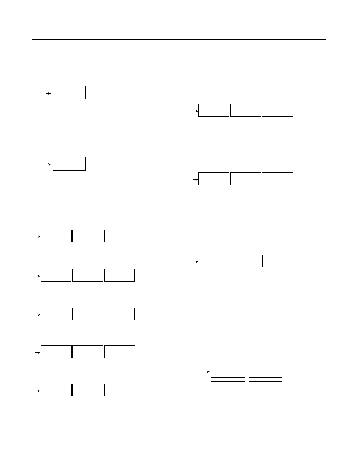
B. Input A Response
Program Item II Selection __________
Consider: Input speed <40Hz? If yes, use contact.
This item is forced to SOLID ST and is not visible if
a QUAD count mode is selected.
Choices:
D
INPUT A
SOLID ST
INPUT A
CONTACT
FINAL P f
P 3
FINAL P f
P 1
F. Reset to Zero/Preset
Program Item 15 Selection __________
Consider: Reset to Preset is considered a down
counting mode for the main counter.
Choices:
D
RESET TO
ZERO
RESET TO
P f
G. Main Counter Auto Cycle
Program Item 16 Selection __________
Consider: Batch counter increments each time the
main counter auto cycles or Pf is reached.
3

INSTALLATION WIRING AND PROGRAMMING - QUICK START
D
RELAY 2 ______
TRANS 1 ______
TRANS 2 ______
Choices:
D
AUTO CYC
DISABLED
AUTO CYC
P 1
AUTO CYC
P f (0)
AUTO CYC
P1 P f (0)
2. When appropriate, adjust the count scaler and set up the
ratemeter in:
PROGRAM
SCALERS
Note: Calculation of scalers and decimal point selection
is explained on page 29.
A. Count Scaler
Program Item 0 Selection __________
C SCALER
D
1.00000
B. Count Decimal Point
Program Item 1 Selection __________
C DEC PT
D
- - - - - -
* * *AT THIS POINT, refer to the block diagram. We are
almost done with figuring out how the counters and ratemeter
are going to behave. All that's left to getting an output to occur
at the terminals on the right side when count pulses come in
at the terminals on the left is to program some "connections"
between the count/rate registers and the output blocks. This
is done in step 3.
3. Educating the outputs:
PROGRAM
OUT MODE
Note: All four output blocks (Relay 1, Relay 2, Trans 1,
and Trans 2) are included in PROGRAM OUT MODE.
The choices for all outputs are exactly the same. Only
Relay 1 choices will be shown here, but spaces for
recording the selections for the other outputs are provided.
RELAY 1
PROGRAM
A. Count or Rate Activated Output
Program Item 300 Selection __________
Consider: Should this output turn on or off based on
a ratemeter setpoint? If yes, choose rate.
C Rate Scaler
Program Item 2 Selection __________
R SCALER
D
1.0000
D. Rate Decimal Point
Program Item 3 Selection __________
R DEC PT
D
- - - - - -
E. Rate Zero Time
Program Item 4 Selection __________
Consider: Maximum ratemeter response time to
the process being considered "stopped".
R ZERO
D
TIME 1.0
F. Rate Average Time
Program Item 5 Selection __________
R AVG
D
TIME 1.0
Choices:
RELAY 1
D
COUNT
RELAY 1
RATE
RELAY 2 ______
TRANS 1 ______
TRANS 2 ______
* * * If RATE is selected, skip to N.
B. Output Operation
Program Item 303 Selection __________
Consider: Reverse mode is also known as contrary
mode. Pick Up events are really Drop Out events
and vise versa.
Choices:
RELAY 1
D
NORMAL
RELAY 1
REVERSE
RELAY 2 ______
TRANS 1 ______
TRANS 2 ______
C. Output Latch / Timeout
Program Item 304 Selection __________
Consider: Latched will require both a Pick Up and
Drop Out event.
Choices:
RELAY 1
LATCHED
RELAY 1
PULSED
4
INSTALLATION WIRING AND PROGRAMMING - QUICK START
* * * If LATCHED is selected, skip to E.
D. Output "On" Time
Program Item 305 Selection __________
RELAY 1
D
PUL 1.00
E. Output On Delay Time
Program Item 306 Selection __________
Consider: How many seconds should elapse after
a Pick Up event occurs before the output actually
picks up?
RELAY 1
D
DEL 0.00
F. Preset 1 Action
Program Item 307 Selection __________
Consider: Should the output Pick Up or Drop Out at
Preset 1 or ignore Preset 1 (No Action)?
Choices:
RELAY 1
D
P1 NA
RELAY 1
P1 PU
RELAY 1
P1 DO
G. Preset 2 Action
Program Item 308 Selection __________
RELAY 1
D
P2 NA
RELAY 1
P2 PU
RELAY 1
P2 DO
H. Preset 3 Action
Program Item 309 Selection __________
RELAY 2 ______
TRANS 1 ______
TRANS 2 ______
RELAY 2 ______
TRANS 1 ______
TRANS 2 ______
RELAY 2 ______
TRANS 1 ______
TRANS 2 ______
RELAY 2 ______
TRANS 1 ______
TRANS 2 ______
K. Output Control 1 Action
Program Item 30C Selection __________
Consider: This signal comes from a control input
programmed to Output Control 1 (OUT CTL 1).
Choices:
D
RELAY 1
OCTL1 NA
RELAY 1
OCTL1 PU
RELAY 1
OCTL1 DO
RELAY 2 ______
TRANS 1 ______
TRANS 2 ______
L. Output Control 2 Action
Program Item 30D Selection __________
Consider: This signal comes from a control input
programmed to Output Control 2 (OUT CTL 2).
Choices:
D
RELAY 1
OCTL2 NA
RELAY 1
OCTL2 PU
RELAY 1
OCTL DO
RELAY 2 ______
TRANS 1 ______
TRANS 2 ______
M. Counter Reset Action
Program Item 30E Selection __________
Consider: This signal comes from a control input
and/or the front panel reset key programmed to
Reset Count (RSC EDG, or RSC LVL).
Choices:
RELAY 1
D
RS C NA
RELAY 1
RS C PU
RELAY 1
RS C DO
RELAY 2 ______
TRANS 1 ______
TRANS 2 ______
* * * This completes the programming for Relay 1 when
it is programmed for count. Go back to choice A at the
beginning of this step and repeat the process for each
remaining output needed.
RELAY 1
D
P3 NA
I. Preset 4 Action
Program Item 30A Selection __________
RELAY 1
D
P4 NA
J. Batch Preset Action
Program Item 30B Selection __________
RELAY 1
D
PB NA
RELAY 1
P3 PU
RELAY 1
P4 PU
RELAY 1
PB PU
RELAY 1
P3 DO
RELAY 1
P4 DO
RELAY 1
PB DO
RELAY 2 ______
TRANS 1 ______
TRANS 2 ______
RELAY 2 ______
TRANS 1 ______
TRANS 2 ______
RELAY 2 ______
TRANS 1 ______
TRANS 2 ______
N. Output Setpoint Assignment
Program Item 301 Selection __________
Consider: Which setpoint, A1 or A2, should this
output respond to, and should it turn on above (hi)
or below (lo) the setpoint?
Choices:
RELAY 1
D
A 1 HI
RELAY 1
A 1 LO
RELAY 1
A 2 HI
RELAY 1
A 2 LO
RELAY 2 ______
TRANS 1 ______
TRANS 2 ______
5
INSTALLATION WIRING AND PROGRAMMING - QUICK START
O. Output Duration
Program Item 302 Selection __________
Consider: Once the output turns on, by what means
will it turn off?
Choices:
RELAY 2 ______
TRANS 1 ______
TRANS 2 ______
D
RELAY 1
DISABLED
RELAY 1
FOLLOWS
RELAY 1
LATCHED
RELAY 1
PULSED
* * * If PULSED is selected, continue to choice P; if not,
go back to choice A and repeat the process for each
remaining output needed.
P. Output "On" Time
Program Item 305 Selection __________
RELAY 1
D
PUL 1.00
RELAY 2 ______
TRANS 1 ______
TRANS 2 ______
* * * This completes the programming for Relay 1 when
it is programmed for rate. Go back to choice A at the
beginning of this step and repeat the process for each
remaining output needed.
Choices:
D
INPUT 1
DISABLED
INPUT 1
BYP P 1
INPUT 1
OUT CTL 1
INPUT 1
OUT CTL 2
INPUT 1
RS C EDG
INPUT 1
RS C LVL
INPUT 1
RS B EDG
INPUT 1
RS T EDG
INPUT 1
RS A EDG
INPUT 1
STOP CNT
INPUT 1
PRINT
INPUT 1
LOCK PGM
INPUT 1
LOCK ALL
INPUT 1
UNL ALMS
INPUT 2 ______
INPUT 3 ______
INPUT 4 ______
Label the assignment of control inputs 1, 2, 3, and 4
(terminals 15, 16, 17 and 18) on the diagram on page 10.
2. Allow the operator to view what's important in:
PROGRAM
DISPLAY
A. Count with text
Program Item 40 Selection __________
Consider: If all items are set to hide, CNT and TXT
will show.
Choices:
Record the assignments of the outputs (terminals 5, 6,
7, 8, 9, 10, 13, 14) on the diagram on page 10.
* * *This completes the wiring and programming selec-
tions for a "bare bones" application. If you check the
block diagram, you can see that count inputs are getting
converted to relay and transistor outputs at this point.
Most applications will need further dressing up before
the control is ready for use by the operator. This is done
in Phase 2.
Phase 2 - Finishing Touches
1. Assigning the control inputs in:
PROGRAM
INPUTS
Input 1 Function
Program Item 20 Selection __________
Consider: Use control inputs wisely and save one for
one of the lock functions.
D
CNT + TXT
HIDE
CNT + TXT
SHOW
B. Rate with text
Program Item 41 Selection __________
Choices:
D
RATE + TXT
HIDE
RATE + TXT
SHOW
C. Batch count with text
Program Item 42 Selection __________
Choices:
D
BCH + TXT
HIDE
BCH + TXT
SHOW
D. Totalizer count with text
Program Item 43 Selection __________
Choices:
D
TOT+ TXT
HIDE
TOT+ TXT
SHOW
6

INSTALLATION WIRING AND PROGRAMMING - QUICK START
D
D
E. Count and current preset
Program Item 44 Selection __________
Choices:
CNT+ Pc
D
HIDE
CNT + Pc
SHOW
F. Count and preset 1
Program Item 45 Selection __________
Choices:
CNT+ P1
D
HIDE
CNT + P1
SHOW
G. Count and preset 2
Program Item 46 Selection __________
Choices:
CNT+ P2
D
HIDE
CNT + P2
SHOW
H. Count and preset 3
Program Item 47 Selection __________
L. Rate and alarm setpoint A1
Program Item 4B Selection __________
Choices:
RATE + A1
HIDE
RATE + A1
SHOW
M. Rate and alarm setpoint A2
Program Item 4C Selection __________
Choices:
D
RATE + A2
HIDE
RATE + A2
SHOW
N. Count scaler
Program Item 4D Selection __________
Choices:
D
C SCALER
HIDE
C SCALER
SHOW
O. Count decimal point position select
Program Item 4E Selection __________
Choices:
CNT+ P3
D
HIDE
CNT + P3
SHOW
I. Count and preset 4
Program Item 48 Selection __________
Choices:
CNT+ P4
D
HIDE
CNT + P4
SHOW
J. Batch and batch preset
Program Item 49 Selection __________
Choices:
BCH + Pb
D
HIDE
BCH + Pb
SHOW
K. Count and rate
Program Item 4A Selection __________
Choices:
D
CNT + RATE
HIDE
CNT + RATE
SHOW
Choices:
D
C DEC PT
HIDE
C DEC PT
SHOW
3. If you intend to use the front panel reset and/or print
keys, enable them in:
PROGRAM
OPTIONS
A. Reset key function
Program Item 80 Selection __________
Choices:
D
RST KEY
DISABLED
RST KEY
RS C EDG
RST KEY
RS C LVL
RST KEY
RS B EDG
RST KEY
RS T EDG
RST KEY
RS D EDG
RST KEY
RS A EDG
B. Print key enable
Program item 81 Selection __________
Consider: If you enable the print key, be sure to
program the item(s) to be printed in PROGRAM
SER OUT.
Choices:
PRNT KEY
DISABLED
PRNT KEY
ENABLED
7
INSTALLATION WIRING AND PROGRAMMING - QUICK START
4. Identify what you're counting in:
PROGRAM
TEXT
You have up to eight characters; select each to be alpha
A Z, numeric 0 9, or space, comma, dash,
decimal point, or slash.
A. Main counter text
Program Item 50 Selection __________
CNT TXT
D
COUNT
B. Ratemeter text
Program Item 51 Selection __________
RATE TXT
D
RATE
C. Batch counter text
Program Item 52 Selection __________
BCH TXT
D
BATCH
D. Totalizer text
Program Item 53 Selection __________
TOT TXT
D
TOTAL
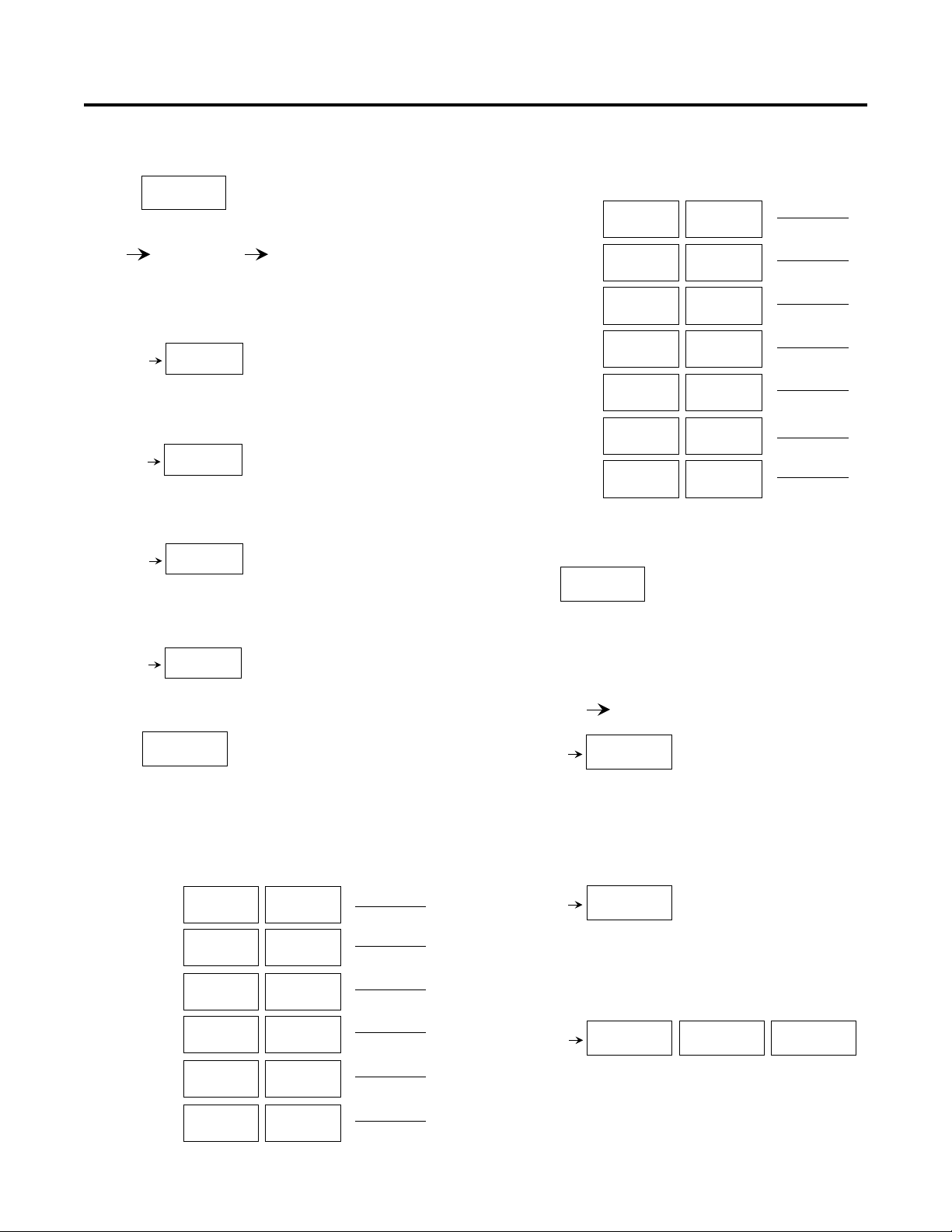
5. Set up your print list in:
Cont.
PROGRAM
ITEM
76
77
78
79
7A
7B
7C
DEFAULT CHOICE
P3
SKIP
P4
SKIP
PB
SKIP
A1
SKIP
A2
SKIP
C SCALER
SKIP
C DEC PT
SKIP
P3
SEND
P4
SEND
PB
SEND
A1
SEND
A2
SEND
C SCALER
SEND
C DEC PT
SEND
SELECTION
6. Configure the serial communications for use with a host
computer or a dumb printer in:
PROGRAM
SER PORT
A. Counter ID number
Program Item 60 Selection __________
Consider: When more than one counter is used in
a system, assign a unique number from the range
of 0 99 to each counter.
PROGRAM
SER OUT
Remember to set the baud rate and parity and set the
port to PRINTER in PROGRAM SER PORT if you are
going to initiate a transmission from the counter.
PROGRAM
ITEM
70
71
72
73
74
75
DEFAULT CHOICE
COUNT
SKIP
BATCH
SKIP
TOTAL
SKIP
RATE
SKIP
P1
SKIP
P2
SKIP
COUNT
SEND
BATCH
SEND
TOTAL
SEND
RATE
SEND
P1
SEND
P2
SEND
SELECTION
SER PORT
D
ID 0
B. Baud rate
Program Item 61 Selection __________
Consider: Choices are 19200, 9600, 4800, 2400,
1200 and 300.
BAUD
D
19200
C. Parity
Program Item 62 Selection __________
Choices:
PARITY
D
NONE
PARITY
ODD
PARITY
EVEN
8

INSTALLATION WIRING AND PROGRAMMING - QUICK START
D. Transmission delay time
Program Item 63 Selection __________
D
Tx DELAY
0.002
Tx DELAY
0.100
E. Host or printer port
Program Item 64 Selection __________
Consider: Should the counter initiate the transmis-
sion (printer), or should the counter respond to a
serial command (host)?
Choices:
HOST
D
PORT
PRINTER
PORT
Label the serial port (terminals 21 and 22) on the
diagram on page 10.
***This completes Phase 2 wiring and programming
selections. All the necessary selections have been made.
Record the selections you have made that are not the default
value in the program menu chart on pages 14 to 21. After you
wire the counter up according to the diagram on page 10, go
into the program mode and give your counter the personality
to do your application.
Phase III - Above and Beyond
A phase 3 installation uses the serial communications port in
the host mode. This capability allows a host computer to read
all programming and run mode information and to write all
programming selections. Furthermore, all of the control input
functions are available through the serial port.
A separate manual describing the serial communications is
available. If you would like a copy, call 1-800-540-9242.
9
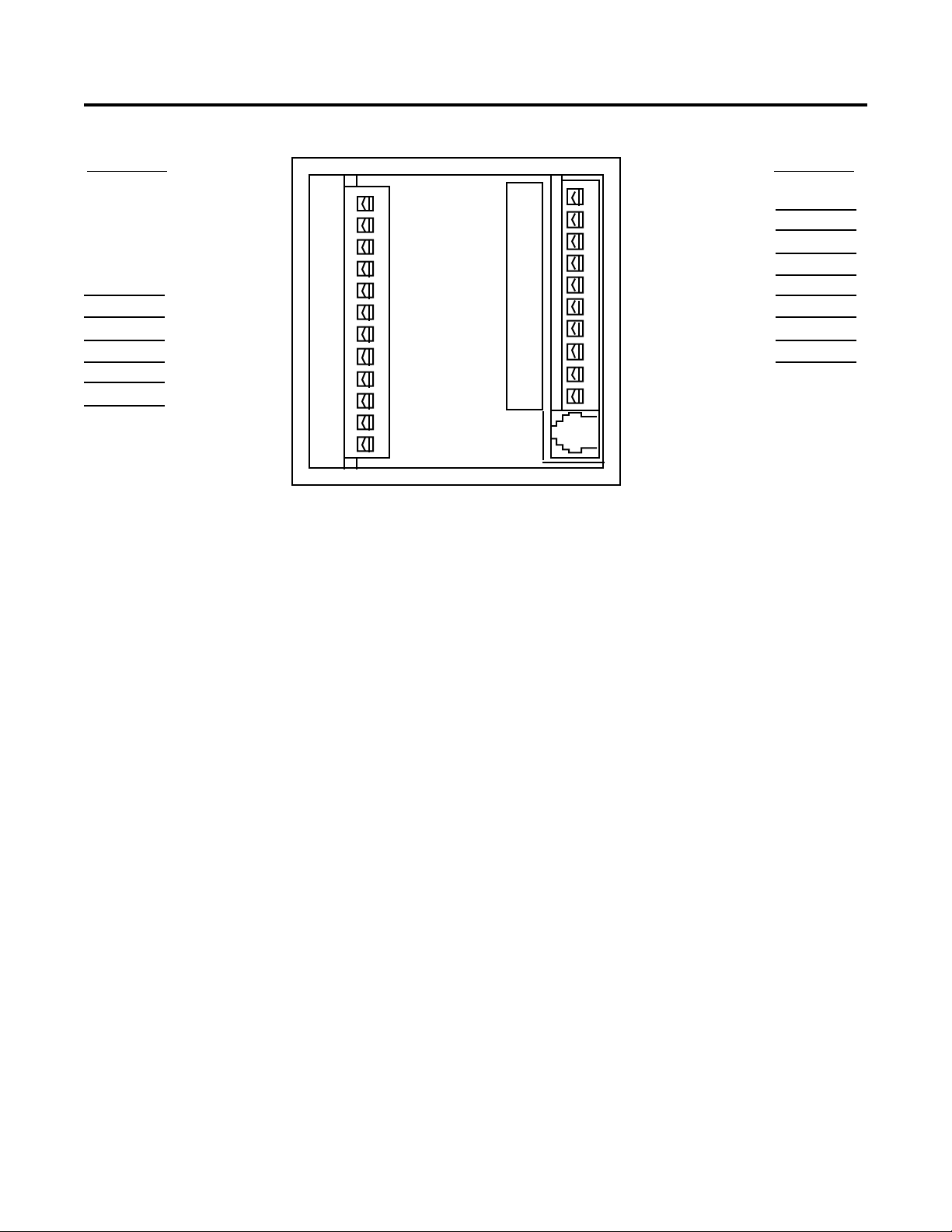
REAR TERMINAL DESCRIPTION
Assignment Assignment
+12 Volt DC
DC Common
DC Common
DC Common
Relay 2 N.C.
Relay 2 Com.
Relay 2 N.O.
Relay 1 N.C.
Relay 1 Com.
Relay 1 N.O.
AC Power Neut
AC Power Hot
TERMINAL DESCRIPTIONS
1 - On models 57601 and 57602 this terminal is the +12 VDC
power output. It is used to supply 12 VDC (+/- 25% 100 mA
max) for accessories. DC Common is the negative side of this
supply.
On the model 57600 this terminal is used for the 10-15 VDC
power input. Connect the positive lead of the power supply to
terminal 1 and the negative lead to DC Common.
The DC POWER OUTPUT contains a series Positive Temperature Coefficient (PTC) resistor that undergoes a large
and abrupt increase in resistance when an over-current
condition occurs. This resistance change limits the fault
current to several milliamps. The PTC device will reset when
the unit power has been removed for a time sufficient to cool
the device. The overload condition should be removed before unit power is reapplied.
2, 3, and 4 - DC Common: These terminals are connected
to the negative side of the counter’s internal DC power
supply. Count inputs must be referenced to DC Common.
Control inputs are on when connected to DC Common.
Transistor outputs conduct to DC Common when picked up.
5, 6 and 7 - Relay 2 contacts
8, 9 and 10 - Relay 1 contacts
Each relay output consists of one electrically isolated form C
set of contacts. The user must supply power through a
contact to the external load. The contacts remain in the
1
2
3
4
5
6
7
8
9
10
11
12
13
14
15
16
17
18
19
20
21
22
normal state until a pickup signal occurs. The relay remains
picked up (on) until a dropout signal occurs (see output
programming diagram page 16 and block diagram page 2).
11 and 12 - AC Power Inputs:
Model 57601-405 115VAC
Model 57602-405 230VAC
Model 57600-405 Not used
13, 14 - Transistor Outputs 2 and 1: These terminals are
separate open collector NPN transistor outputs. Each output
conducts to DC Common when picked up (see output programming diagram page 16 and block diagram page 2).
15, 16, 17, and 18 - Inputs 1, 2, 3, and 4: Programmable
inputs. The user can assign one of 14 functions to each
individual input. The inputs require a current sinking signal
(contact or solid state) to DC Common (see input programming diagram page 15 and block diagram page 2).
19, 20 - Count Inputs B and A: Connect the count input
signal(s) to these terminals. The count input can operate with
either a current sinking signal (contact or solid state) to DC
Common or a current sourcing signal. (See specifications,
programming diagram page 14, and block diagram page 2.)
Rate calculations are made from count pulses into Input A
only.
21, 22 - RS-485 serial I/O port: Connect terminal 21 to the
positive lead of the communications bus. Connect terminal
22 to the negative lead of the communications bus.
Transistor 2 Output
Transistor 1 Output
Input 1
Input 2
Input 3
Input 4
Count Input B
Count Input A
Communication +
Communication -
RS-485 communication connector, RJ-11 modular telephone style.
10

REAR TERMINAL DESCRIPTION continued
MODULAR COMMUNICATION JACK
The modular phone jack is an alternate connection to the RS485 communications port. Pin 3 is positive and is the same
as terminal 21. Pin 2 is negative and is the same as terminal
22. Pins 1 and 4 are connected to DC Common and should
be used for any shield connections.
Note: This jack is intended only for connection to Ambassador and other RS-485 communication networks. It should
not be connected to any telephone system - damage or hazard may result.
!
TERMINAL BLOCKS
Connections to the Ambassador are made through deplugable, screw terminal blocks to allow for ease of wiring and
removal of the counter. The terminals can accommodate
stranded, solid or fused wire (preferred) from 14 to 22 gauge.
To remove the terminal block, remove AC power and pry
gently underneath each end of the terminal block with small
screwdriver. Press straight on to re-install.
GENERAL WIRING PRACTICES
1. Disconnect all power before wiring terminals. A
safety hazard exists if this precaution is not
observed. Treat all control and count inputs as
hazardous since they may carry line voltage.
2. Use shielded cables for count signals, control input and
communications signals. Connect shield to common
(terminal 2, 3 or 4) of counter to terminate properly.
3. Keep all signal lines as short as possible.
4. Do NOT bundle or route signal lines with power or
machine control wiring. Use separate conduit for power
and signal wires.
5. Provide "clean" power to the counter. In severe cases,
power may have to be filtered or a separate power
source used. Do not use the same power source that is
supplying the loads.
6. Use 18 ga. minimum (0.97mm
maximum (2.1mm2, 600V) wire for AC power wiring.
7. See page 26, top drawing, for the correct fuse to be used
in the power input wiring.
DIP SWITCH FUNCTIONS
Switch 1: Input A sink/source
Off: input A requires a current sinking input signal.
On: input A requires a current sourcing input signal.
Switch 2: Input B sink/source
Off: input B requires a current sinking input signal.
On: input B requires a current sourcing input signal.
2
, 600V) and 14 ga.
Switch 3: Input A threshold level
Off: high threshold level — use with DC sensors.
On: low threshold level — use with mag pickups. Turn
switch 1 on.
Switch 4: Input B threshold level
Off: high threshold level — use with dc sensors.
On: low threshold level — use with mag pickups. Turn
switch 2 on.
Dip switches may be set through an opening on the bottom
of the unit. It is located towards the rear of the control.
PANEL MOUNTING
The panel mounting kit includes:
(1) mounting gasket, (2) mounting clips and (4) screws.
Refer to the dimension diagram on page 37 for a drawing of
the correct installation of these parts.
The mounting gasket is coated on one side with a contact
adhesive and a paper backing. Care should be taken during
the gasket installation that the gasket be correctly positioned
on the panel at the first attempt. Attempting to re-position the
gasket once the adhesive has come in contact with the panel
is likely to deform or tear the gasket.This may result in an
improper seal. For best results, follow these directions:
1. Stand the Ambassador counter on a desk or table with
its display down, screw terminals up.
2. Remove and discard the center square of the gasket at
the scribe marks in the gasket and paper backing. Do not
remove the backing from the remaining outer rim.
3. Slide the gasket down the unit until it is in position at the
rear of the unit's front bezel. The paper backing side
should be up.
4. Insert the tip of a knife between the paper and the gasket
and, while holding the gasket down to the unit with the
knife, peel off the paper backing.
5. Slide the unit through the panel cutout until the gasket
firmly adheres to the panel.
6. Install the mounting clips and screws as shown in the
diagram on page 37. Do not overtighten the mounting
screws. The screws should be tight enough to firmly hold
the unit in place, but not so tight as to squeeze the gasket
out from behind the front bezel.
7. A switch shall be included in the building installation:
• It shall be in close proximity to the equipment and
within easy reach of the operator.
• It shall be marked as the disconnecting device for the
equipment.
• Switches and circuit breakers in Europe must comply
with IEC 947.
11
 Loading...