

DuraMax Vinyl Owner's Manual/ Instructions For Assembly
TM
A Product of
ALL PURPOSE VINYL GARAGES
Vinyl Garage
Vinyl Garage
Garage
Garage
USP
USP
US POLYMERS INC
OWNER’S MANUAL /
Instructions for Assembly
Size 10’x 15’
Ver: 1.0
Patent #416.091
Your Total Solution To maintenance Free Garages.
• All Weather Durable PVC
• Won’t Dent, Rust, Rot or Mildew
• Tall Walk In Shed
• Never Needs Painting
• 89” Wide Double Doors
• Easy Assembly
• High Wind Tested
• Snow Load Tested 20lbs/sq. foot
• Pad Lock Ready (Lock not included)
Available Kits
• Window Kits Available
Customer
Service Hotline
(800) 483-4674
www.uspolymersinc.com
Requires two people and takes about
4-5 hours for Installation.
Call us for any missing or damaged parts.
Do not return to the store.

Duramax Garages
Limited Ten Year Warranty
U.S. Polymer Inc. will send a replacement part free of charge, in the event of material defects and or
workmanship for a period of ten years from the date of purchase.
This warranty is extended only to the original purchaser. A purchase receipt or other proof of date of
original purchase will be required before warranty service is rendered. In no event shall we pay the
cost of flooring, labor, installation or any other costs related thereto.
This warranty only covers failures due to defects in material or workmanship which occurs during normal
use and does not extend to color change arising due to normal weathering or to damage resulting from
misuse or neglect, commercial use, failure to follow assembly instructions and the owner’s manual
(including proper anchoring of the shed), painting, forces of nature and other causes which is beyond
our control.
Claims under this warranty must be made within the warranty period by calling 1-800-483-4674 or mail
in a dated sales slip and clear photograph of the part to:
U.S. Polymers, Inc.
6915 Slauson Avenue
Commerce, CA 90040
We reserve the right to discontinue or change components. If a component has been discontinued
or is not available,
U.S. Polymers, Inc. reserves the right to substitute a component of equal quality as may be compatible.
Limits and Exclusions
There are no express warranties except as listed above. The warrantor shall not be liable for incidental
or consequential damages resulting from the use of this product, or arising out of any breach of this
warranty. All express warranties are limited to the warranty period set forth above . Some states do
not allow the exclusion or limitation on how long an implied warranty lasts, so the above limitations may
not apply to you.
This warranty gives you specific legal rights and you may also have other rights which vary from state
to state or country to country.
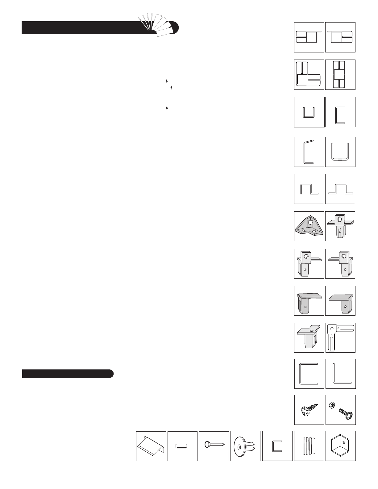
Parts List
Note: Check all parts prior to installation.
CODE DESCRIPTION QTY
B1LH FRONT ‘U’ CHANNEL LEFT 1
B1RH FRONT ‘U’ CHANNEL RIGHT 1
B1LA FRONT ‘U’ CHANNEL LEFT 1
B1RA FRONT ‘U’ CHANNEL RIGHT 1
B21 SIDE ‘U’ CHANNEL 1
B22 SIDE ‘U’ CHANNEL 1
B3LA BACK ‘U’ CHANNEL LEFT 1
B3RA BACK ‘U’ CHANNEL RIGHT 1
EXTL EXTENSION ‘U’ CHANNEL LEFT 3
EXTR EXTENSION ‘U’ CHANNEL RIGHT 3
CMA MIDDLE COLUMN 8
CMH MIDDLE COLUMN 3
CCA CORNER COLUMN 4
CDLA LEFT DOOR COLUMN 1
CDLH LEFT DOOR COLUMN 1
CDRA RIGHT DOOR COLUMN 1
CDRH RIGHT DOOR COLUMN 1
CB1A CB1 CENTER BAND 1
CB1H CB1 CENTER BAND 2
CB3A CB3 CENTER BAND 1
CB3XA CB3 CENTER BAND 5
CB4A CB4 CENTER BAND 1
CB4H CB4 CENTER BAND 2
CB6H CB6 CENTER BAND 1
RS1H RS1 ROOF STRUCTURE 4
RS2A RS2 ROOF STRUCTURE 4
RS3LA RS3 ROOF STRUCTURE LONG 5
RS3LH RS3 ROOF STRUCTURE LONG 1
RS4XA RS4 ROOF STRUCTURE 10
RS5A RS5 ROOF SRTUCTURE 4
RS6H RS6 ROOF STRUCTURE 8
RS7H RS7 ROOF STRUCTURE 8
RS13A RS13 ROOF STRUCTURE 8
RS8H RS8 ROOF STRUCTURE SUPP. LONG 4
RS9H RS9 ROOF STRUCTURE SUPP. SHORT 4
MJ MIDDLE JOINING SUPPORT 9
RS10A RS10 ROOF STRUCTURE SUPPORT 2
RS11A RS11 ROOF STRUCTURE SUPPORT SHORT 5
RS12A RS12 ROOF STRUCTURE SUPPORT LONG 3
RS14A SAGGING SUPPORT 24
DSHH DOOR STOPPER HORIZONTAL 1
RS19H VERTICAL SUPPORT - 1 4
RS20H VERTICAL SUPPORT - 2 4
RS15L RS15 ROOF STRUCTURE SUPPORT LEFT 2
RS15R RS15 ROOF STRUCTURE SUPPORT RIGHT 2
Tools You Will Need
Cordless Drill - Philips Head
Hammer or Rubber mallet
Carpenters Square
8’ Step Ladder
Adjustable pliers
Level - 3ft.
Tape Measure
Caulk Gun
Waterproof Clear Silicon
Sealant
Hand Gloves
RAMP (RG)
CODE DESCRIPTION QTY
RS16L DOOR STOPPER LEFT 1
RS16R DOOR STOPPER RIGHT 1
RG RAMP 2
SP SIDE PANEL 15
FSPH FRONT SIDE PANEL 2
FPL FACIA PANEL LEFT 2
FPR FACIA PANEL RIGHT 2
RP ROOF PANEL 12
RRS RIDGE COVER 6
DL LEFT DOOR 1
DR RIGHT DOOR 1
DS DOOR SMALL 1
ACCESSORIES
CODE DESCRIPTION QTY
FDCL DOOR COLUMN FITTING LEFT 1
FDCLC DOOR COLUMN FITTING LEFT 1
FDCR DOOR COLUMN FITTING RIGHT 1
FDCRH DOOR COLUMN FITTING RIGHT 1
FCC CORNER COLUMN FITTING 4
FMC MIDDLE COLUMN FITTING 11
FCB CENTER BAND FITTING 4
RJ 90 DEGREE JOINT 4
PPG ROOF PLUG WITH WASHER 128
PIN ROOF PIN 128
EPS END PLUG SQUARE 7
CBC CENTER BAND COVER 3
TCH TOP CORNER 8
S1 DIA. 4.2 x 16mm. (5/32” x 5/8”)
SHEET METAL SCREW 420
S2 DIA. 4.2 x 32mm. (5/32” x 1 1/4”)
SHEET METAL SCREW 16
S7 DIA. 4.2 x 10mm. (5/32” x 3/8”)
SHEET METAL SCREW 40
S3 M4 x 10mm. (M5/32” x 3/8”)
MACHINE SCREW WITH NUT 33
S8 M6 x 20mm. (M1/4” x 3/4”)
HEX. BOLT & NUT WITH WASHER 9
FOUNDATION
CODE DESCRIPTION QTY
F01H FOUNDATION ‘U’ CHANNEL 2
F02H FOUNDATION ‘U’ CHANNEL 2
F03 FOUNDATION ‘L’ ANGLE 4
F04A FOUNDATION ‘U’ CHANNEL 6
F05A FOUNDATION ‘U’ CHANNEL 6
F06A FOUNDATION ‘U’ CHANNEL 21
F07 FOUNDATION ‘U’ CHANNEL 18
F03H FOUNDATION ‘U’ CHANNEL 4
F08 FOUNDATION ‘U’ CHANNEL JOINT 8
S1 DIA. 4.2 x 16mm. (5/32” x 5/8”)
SHEET METAL SCREW 150
SAGGING SUPPORT (RS14A)
ROOF PIN (PIN)
ROOF PLUG WITH
WASHER (PPG)
CENTER BAND COVER (CBC)
LEFT DOOR COLUMN
(CDLA) (CDLH)
CORNER COLUMNS (CCA)
ROOF STRUCTURES (RS - 1H,
3LH, 3LA, 8H, 9H,19H,20H) (CB 1A,1H, 2A, 3A, 4A,4H,6H) (MJ)
ROOF STRUCTURE
(RS5A)(RS6H) (RS7H)
ROOF SUPPORT (RS2A)
(RS10A)
CENTER BAND FITTING
(FCB)
DOOR COLUMN FITTING
(FDCL)
DOOR COLUMN FITTING
(FDCLC)
CORNER COLUMN FITTING
(FCC)
FOUNDATION ‘U’ CHANNEL
(F01H,2H,3H,F04A,5A,6A,F07)
SHEET METAL SCREW
(S1), (S2), (S7)
END PLUG SQUARE (EPS)
RIGHT DOOR COLUMN
(CDRA) (CDRH)
MIDDLE COLUMNS
(CMA) (CMH)
DOOR STOPPER
(DSHH)
U-Channels (B1LA, RA, LH,
RH)(B21) (B22) (B3LA) (B3RA)
ROOF SUPPORT (RS4XA)
(RS11A) (RS12A)
MIDDLE COLUMN FITTING
(FMC)
DOOR COLUMN FITTING
(FDCR)
DOOR COLUMN FITTING
(FDCRH)
PVC 90 DEGREE JOINT
(RJ)
FOUNDATION ‘L’ ANGLE
(F03)
MACHINE SCREW
(S3)
TOP CORNER
(TCH)
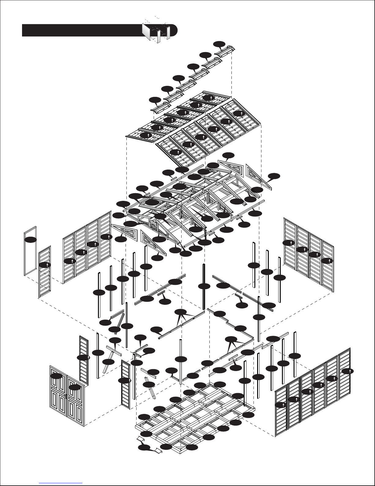
Exploded View
DS
SP
SP
DL
DR
SP
SP
FSPH
SP
CDRH
CDLA
SP
CB1A
CB4H
CDLH
CB4A
CB1H
RS3LH
RS1H
FPL
CMA
FSPH
RS16L
CCA
RS4XA
RS2A
CMH
B1RA
CDRA
RP
MJ
CMA
CB6H
F04A
F01H
RG
RS15RRS15L
B1LH
CB1H
CB4H
RRS
RP
RS3LA
RS5A
RS16R
FPR
B1LA
F05A
RRS
MJ
RS6H
MJ
F02H
RP
RS1H
CB3XA
B1RH
RRS
RP
RS3LA
RS4XA
EXTL
CCA
F07
RP
RS2A
RP
F07
F04A
RRS
RP
RS4XA
RS15R
RS3LA
B22
RP
RS1H
RS4XA
CCA
F07
RRS
RP
RS7H
B21
F05A
RP
RS2A
RRS
RS4XA
MJ
CB3XA
B3LA
CB3XA
F02H
F07
RP
FPR
RS3LA
EXTR
RP
RS4XA
B3RA
MJ
F01H
F07
MJ
MJ
CB3XA
CMA
RS1H
F07
RS2A
RS3LA
CMA
CCA
CMH
CMA
CB3XA
CB3A
CMA
FPL
SP
SP
SP
SP
CMA
CMA
CMH
SP
SP
SP
SP
SP
SP
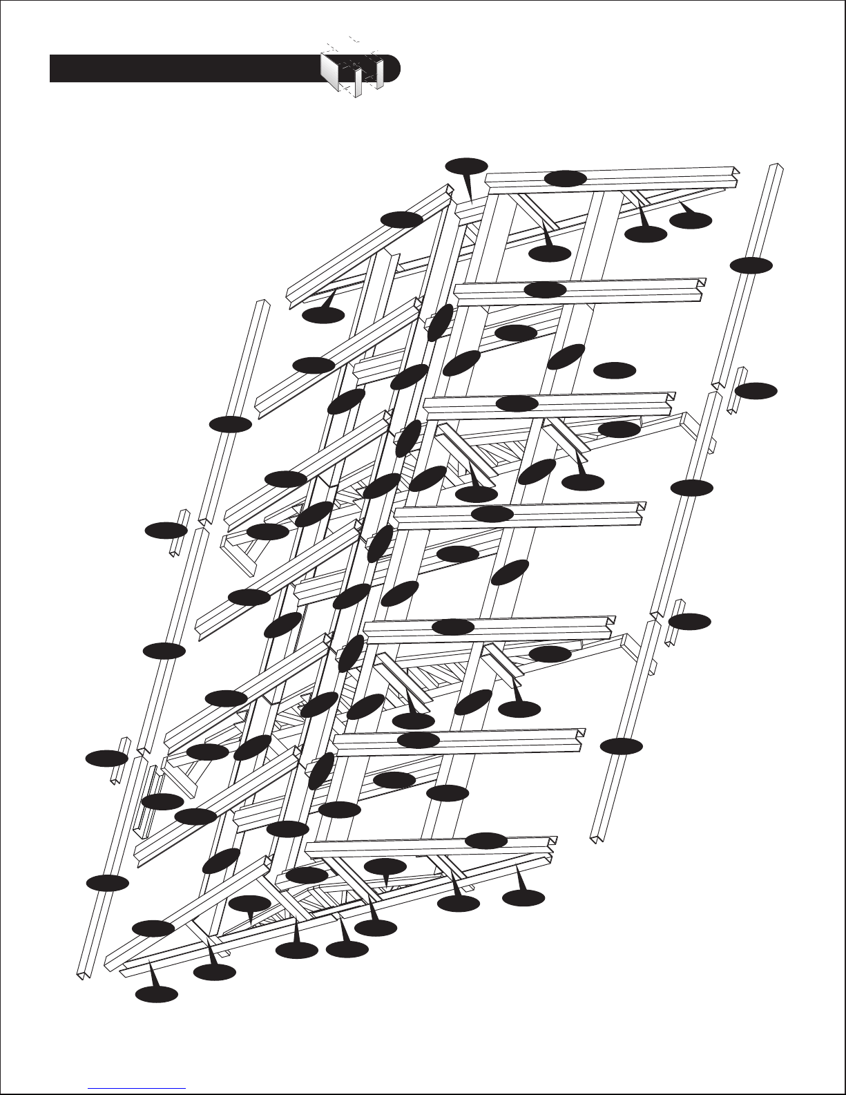
Roof Structure Exploded View
MJ
RS3LA
RS3LA
RS4XA
RS4XA
RS15L
RS6H
RS1H
RS4XA
RS6H
RS6H
RS6H
RS11A
RS2A
RS6H
RS11A
RS7H
RS6H
RS11A
RS7H
RS10A
RS11A
RS7H
RS12A
RS4XA
RS19H
RS4XA
RS12A
RS4XA
RS7H
RS8H
RS4XA
RS7H
RS15R
RS2A
RS7H
RS20H
RS9H
RS1H
RS3LA
RS2A
MJ
RS15R
RS3LA
MJ
RS4XA
MJ
DSHH
RS3LH
RS2A
RS1H
RS15L
RS4XA
RS9H
RS6H
RS5A
RS5A
RS16L
RS8H
RS6H
RS10A
RS11A
RS5A
MJ
RS7H
RS16R
RS8H
RS19H
RS12A
RS4XA
RS5A
RS9H
RS7H
RS2A
RS20H
RS3LA
RS1H
A. Foundation
Note: It is important that these instructions
are followed step by step.
Note
All parts are clearly marked and care should
be taken to use the correct one.
Parts Needed:
(2) Foundation ‘U’ Channel (F01H)
(2) Foundation ‘U’ Channel (F02H)
(4) Foundation ‘L’ Angle (F03)
(6) Foundation ‘U’ Channel (F04A)
(6) Foundation ‘U’ Channel (F05A)
(21) Foundation ‘U’ Channel (F06A)
(18) Foundation ‘U’ Channel (F07)
(4) Foundation ‘U’ Channel (F03H)
(8) Foundation ‘U’ Channel Joint (F08)
(1) Base ‘U’ Channel (B1LH)
(1) Base ‘U’ Channel (B1RH)
(1) Base ‘U’ Channel (B1LA)
(1) Base ‘U’ Channel (B1RA)
(1) Base ‘U’ Channel (B21)
(1) Base ‘U’ Channel (B22)
(1) Base ‘U’ Channel (B3LA)
(1) Base ‘U’ Channel (B3RA)
(3) Base ‘U’ Channel (EXTL)
(3) Base ‘U’ Channel (EXTR)
Screws (S1)
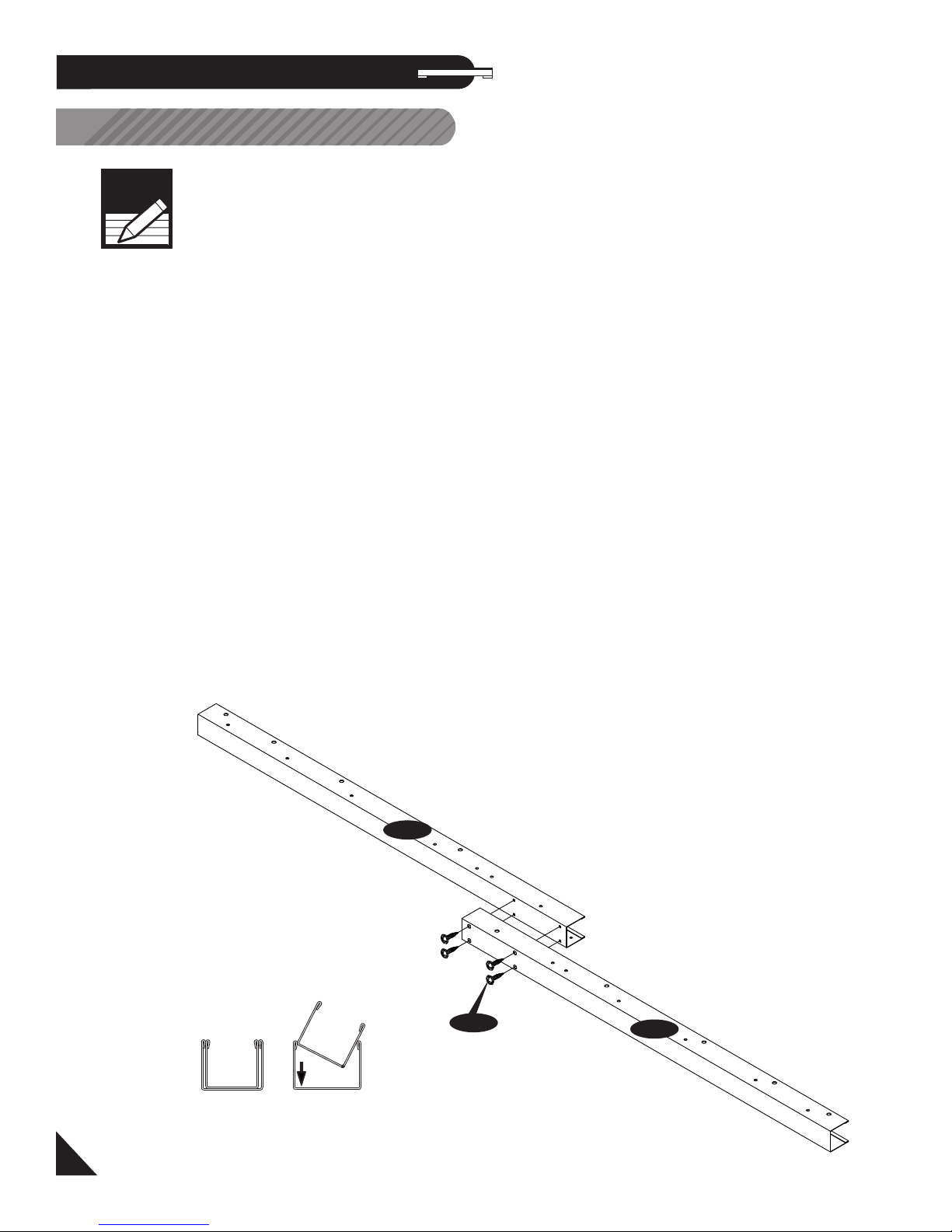
1. Assemble the channel (F01H) & (F02H) together
using 4 (S1) screws. Make 2 sets.
F01H
S1
F02H
Over lapping
1
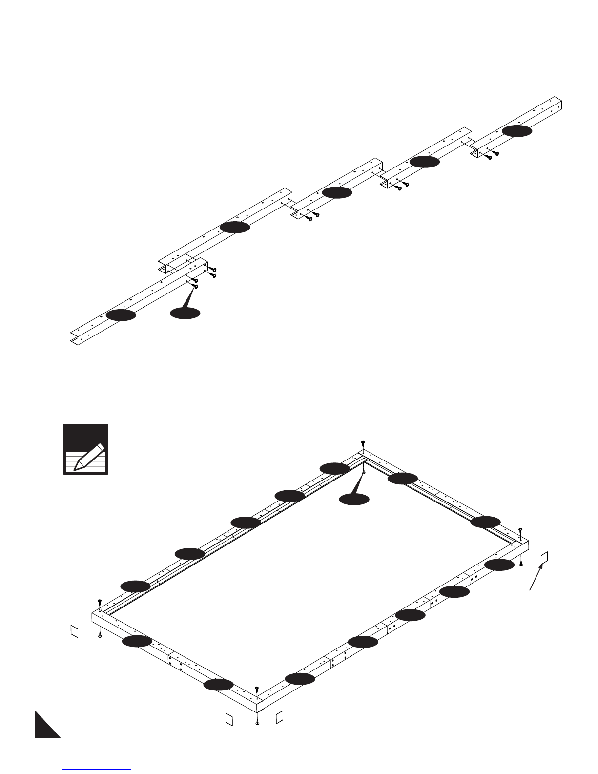
2. Assemble the channel (F04A), (F05A) & (F07)
together using (S1) screws. Make 6 sets.
F05A
F07
F07
F07
F04A
S1
3. Make a frame with the sub assemblies as shown
below.
Note
Make sure while assembling, the
channel position should be as
shown.
F07
F05A
F04A
F07
F07
S1
F01H
F07
F02H
F07
Channel Position
F01H
Front
2
F02H
F07
F05A
F04A
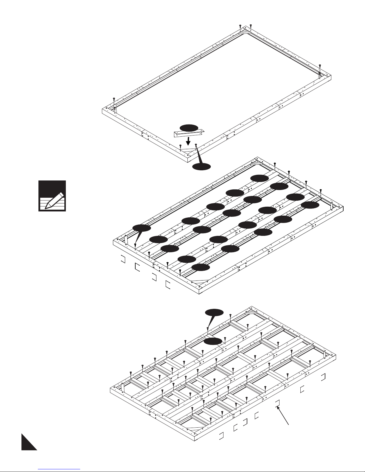
4. Fix the ‘L’ angle (F03) to the channel at all the
four corners to make a perfect frame. See fig.
F03
5. Fix the channel (F04A), (F05A) & (F07) sub
assembly into the main frame as shown. See fig.
Note
Make sure while assembling, the
channel position should be as
shown.
S1
F04A
F04A
Front
6. Fix the channel (F06A) into the frame with (S1)
screws as shown. See fig.
F05A
F04A
S1
F05A
F04A
F07
F05A
S1
F07
F05A
F07
F07
F07
F07
F07
F07
F07
F07
F07
F07
3
F06A
Channel Position
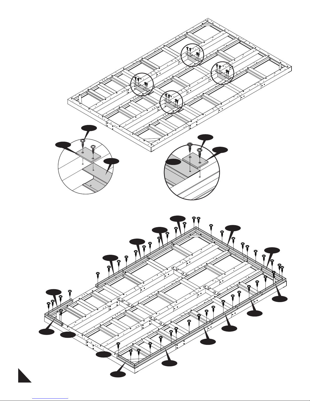
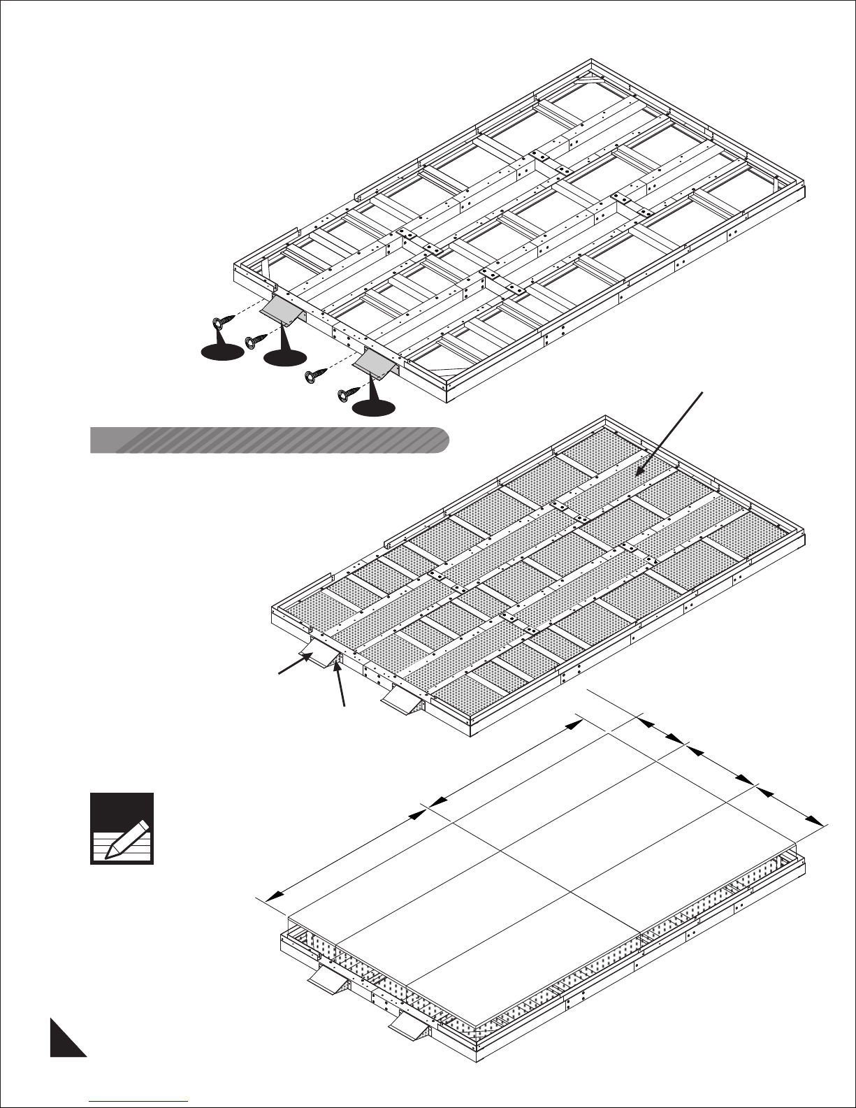
7. Place the channel (F03H) into the frame equaly
spaced as shown. Use (F08) plate to connect the
‘U’ channel and the frame with (S1) screws.
S1
F08
S1
F08
F03H
8. Assemble the Base U-Channel on top of the
foundation with (S1) screws as shown in fig.
EXTL
B1LA
B1RA
EXTL
F03H
EXTL
B3LA
B3RA
EXTR
B1LH
F01H
Front
F02H
4
EXTR
EXTR
B21
B22
B1RH
9. Place the ramp (RG) to the front side of the
foundation and keep the distance according to the
wheel distance. Use dia. 2.5mm. drill bit to transfer
the hole from (RG) and fix with (S1) screws.
S1
RG
RG
Filler Material and Flooring Recommendation
OPTION - 1.
Gravel Floor with Plywood
a. After completing the assembly of the base U-
channel fill the gravel up to the foundation top
surface only.
Fill the concrete inside the ramp only.
Ramp
Concrete
b. Place the exterior grade CDX 3/4” (19mm.)
plywood on top of the foundation. (Plywood not
included.)
Note
Plywood should be place after
completing the side panel
assembly.
Gravel
684mm.
1220mm.
2265mm.
1220mm.
5
2440mm.
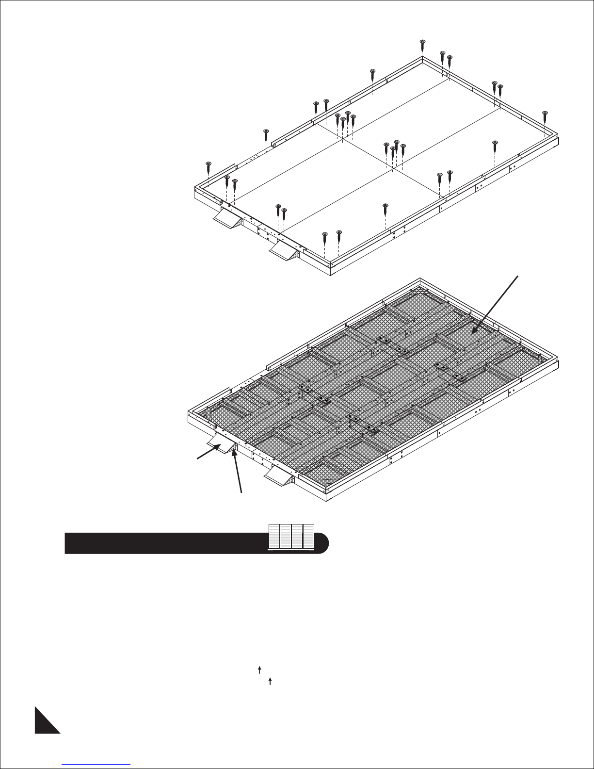
c. Secure the plywood to the foundation with
screws. (Screws not included.)
OPTION - 2.
Cement Floor with out Plywood.
After completing the assembly of the base U-channel
fill the concrete up to the foundation top surface
only.
Concrete
Ramp
Concrete
B. Walls & Columns
Parts Needed:
(1) Door Column (CDRA)
(1) Door Column (CDLA)
(1) Door Column (CDRH)
(1) Door Column (CDLH)
(8) Middle Column (CMA)
(3) Middle Column (CMH)
(4) Corner Column (CCA)
(15) Side Panel (SP
(2) Front Side Panel (FSPH
(2) CB1 Center Band (CB1H)
(1) CB1 Center Band (CB1A)
(1) CB3 Center Band (CB3A)
)
)
6
(5) CB3 Center Band (CB3XA)
(2) CB4 Center Band (CB4H)
(1) CB4 Center Band (CB4A)
(1) CB6 Center Band (CB6H)
(3) Middle Joining Support (MJ)
(2) Ramp (RG)
(4) Center Band Fitting (FCB)
(3) Center Band Cover (CBC)
(7) End Plug Square (EPS)
Screws (S1)
Screws (S2)
Machine Screws (S3)
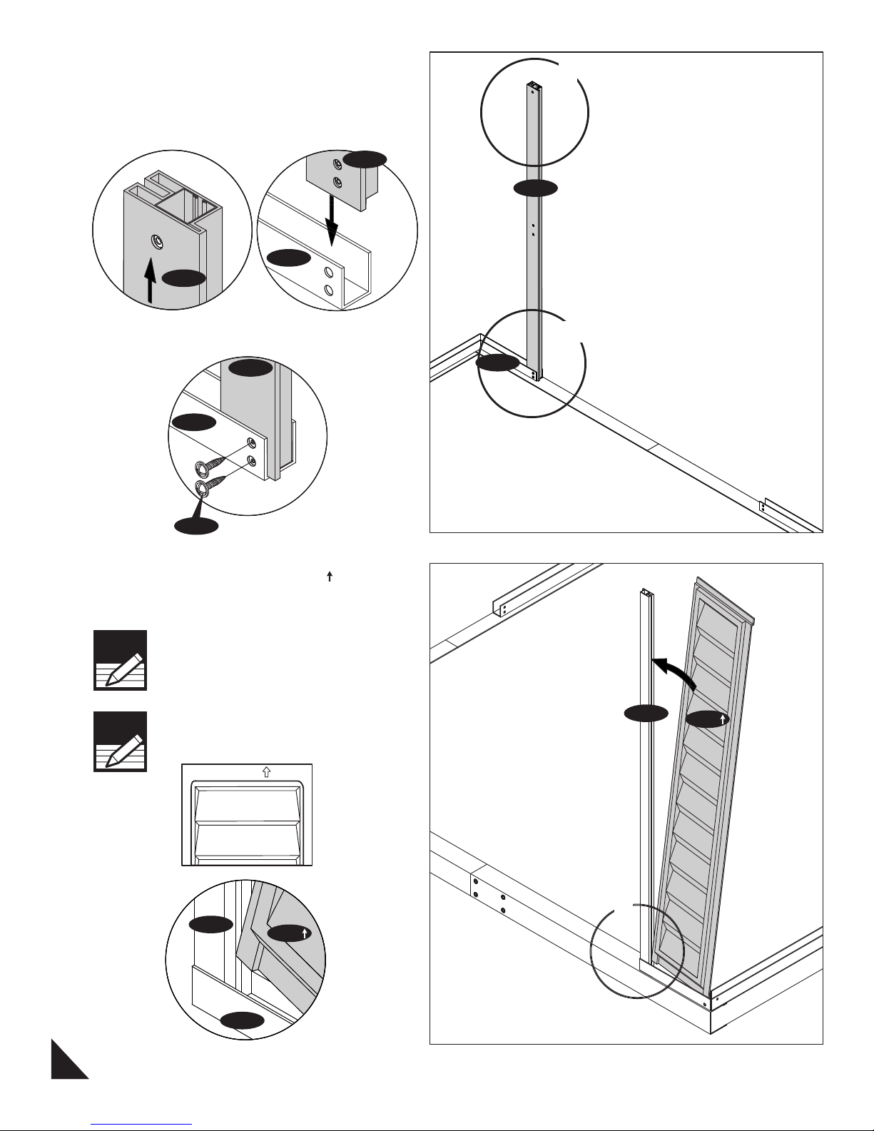
1. Slide the door column (CDRA) into the base
U-channel (B1RH) on the right side of the door.
Line up the pre drilled holes on column (CDRA)
with base ‘U’ channel. Secure with two (S1) screws
from inside. See fig.
CDRA
B1RH
CDRA
1
CDRA
Fig.1
B1RH
S1
CDRA
Fig.3
Fig.2
2. Insert the front side panel (FSPH ) into the
groove of column (CDRA). Start at the bottom of
the panel at an angle then push into place.
Note
Note
Always place panels into frame at an angle
on top and slide in sideways and
downward for easy insertion.
Make sure panels are right side up with
panel shingles facing down. Check the
stamped label on top of all panels.
FSPH
B1RH
2&3
Front
CDRA
FSPH
CDRA
B1RH
7
Fig.1
FSPH
1
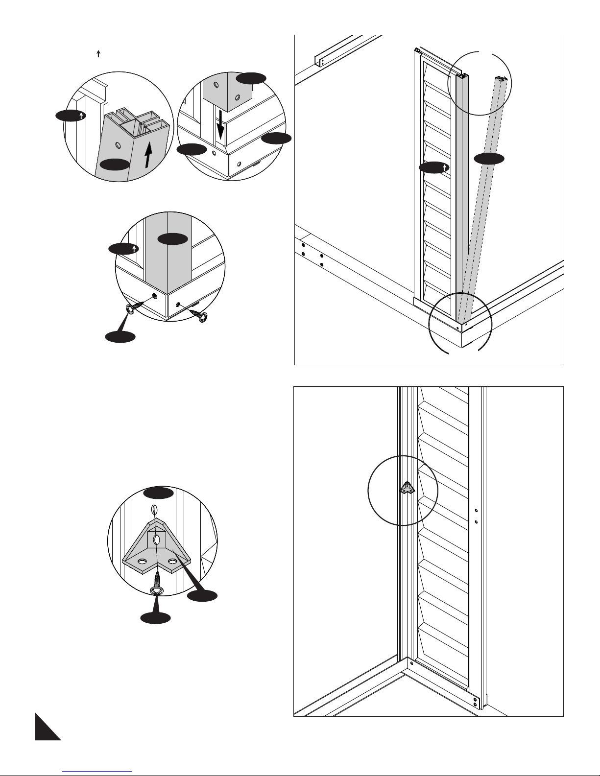
3. Slide the corner column (CCA) into side panel
(FSPH ) pushing the column to the side panel.
CCA
FSPH
B1RH
CCA
1
B22
CCA
FSPH
Fig.1
FSPH
S1
CCA
Fig.3
Fig.2
4. Fix the center band fitting (FCB) to the column
(CCA) with (S2) screw. Leave it loose.
2&3
CCA
FCB
S2
8
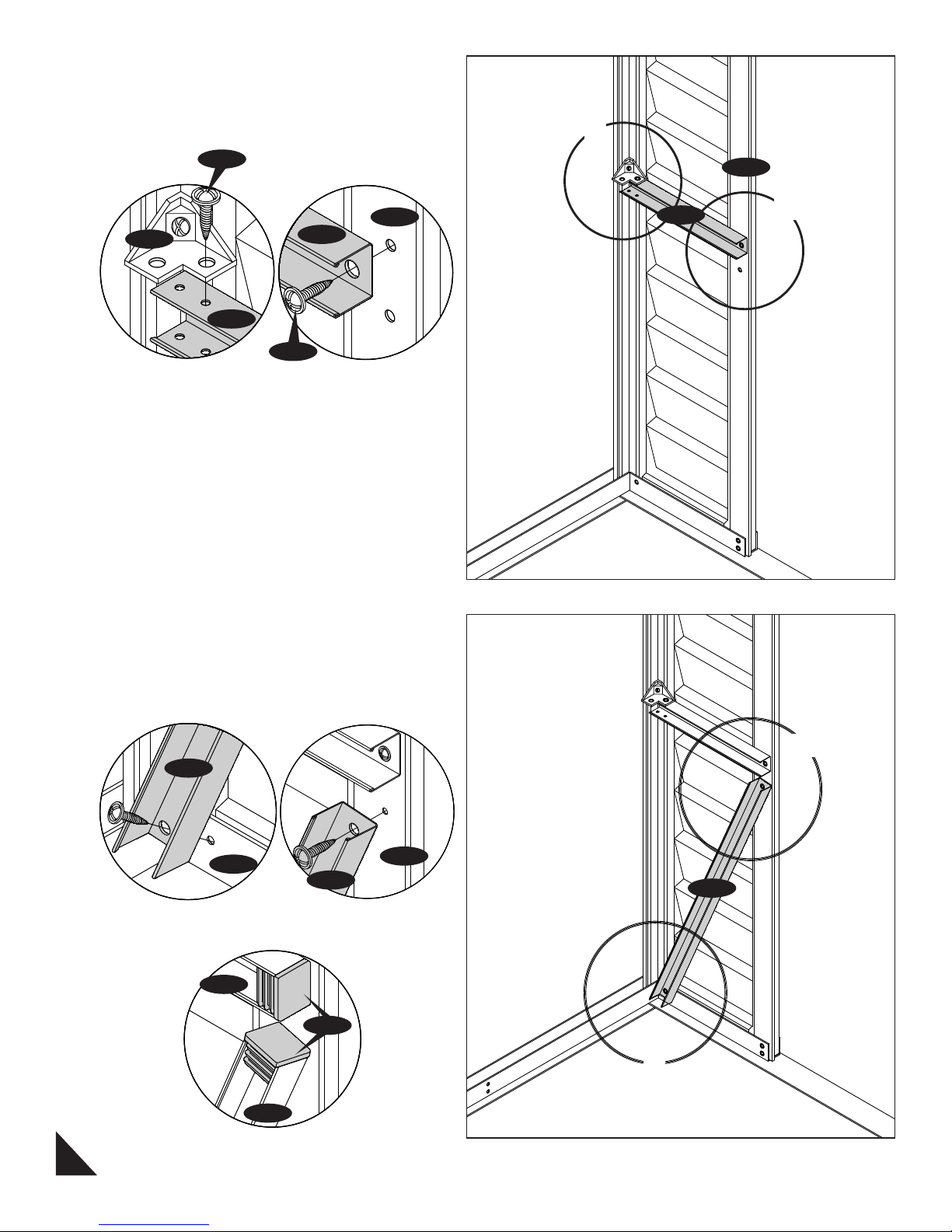
5. Fix the center band (CB1H) to the center band
fitting (FCB) with (S1) screws. See fig.1. Fix the
other end to the door column (CDRA). See fig.2.
1
S1
FCB
CB1H
CB1H
S1
Fig.1 Fig.2
CDRA
CB1H
CDRA
2
6. Fix the center band (CB4H) to the base ‘U’
channel (B1RH) and door column (CDRA) with
(S1) screws. See fig.1&2. Fix the (EPS) at the end
of (CB1H) & (CB4H). See fig.3.
CB4H
B1RH
CB4H
Fig.1
CB1H
EPS
CDRA
Fig.2
2&3
CB4H
1
CB4H
Fig.3
9
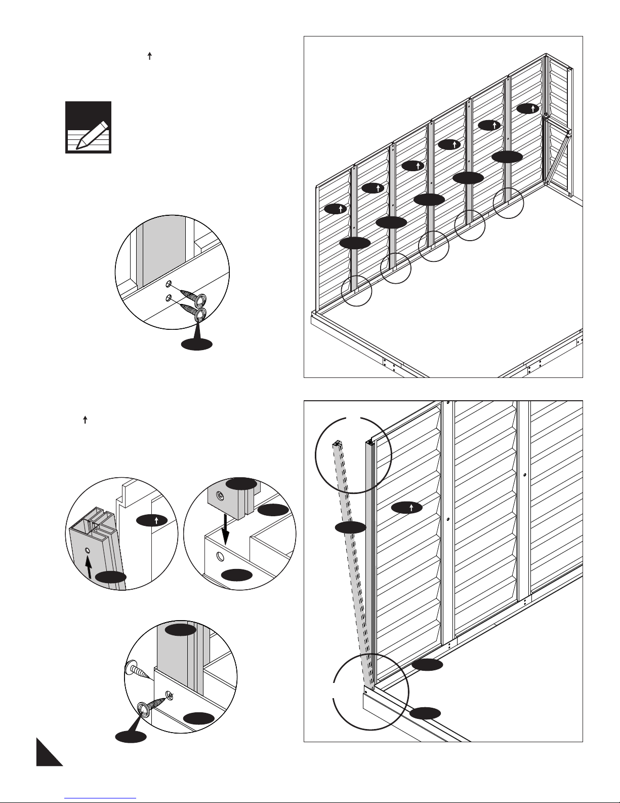
7. Working from inside continue connecting the
6 side panels (SP
channel. Use (S1) screws to fix column to base.
) and columns to the base ‘U’
Note
Window can be fixed any place
except front panel.
S1
SP
SP
SP
CMA
SP
CMH
SP
CMA
SP
CMH
CMA
8. Slide the corner column (CCA) into side panel
(SP
) pushing the column to the side panel.
Working from outside use (S1) screws to secure
column to base (EXTR) & (B3RA).
CCA
EXTR
SP
CCA
Fig.1
CCA
B3RA
Fig.2
1
SP
CCA
EXTR
2&3
B3RA
S1
Fig.3
10
B3RA
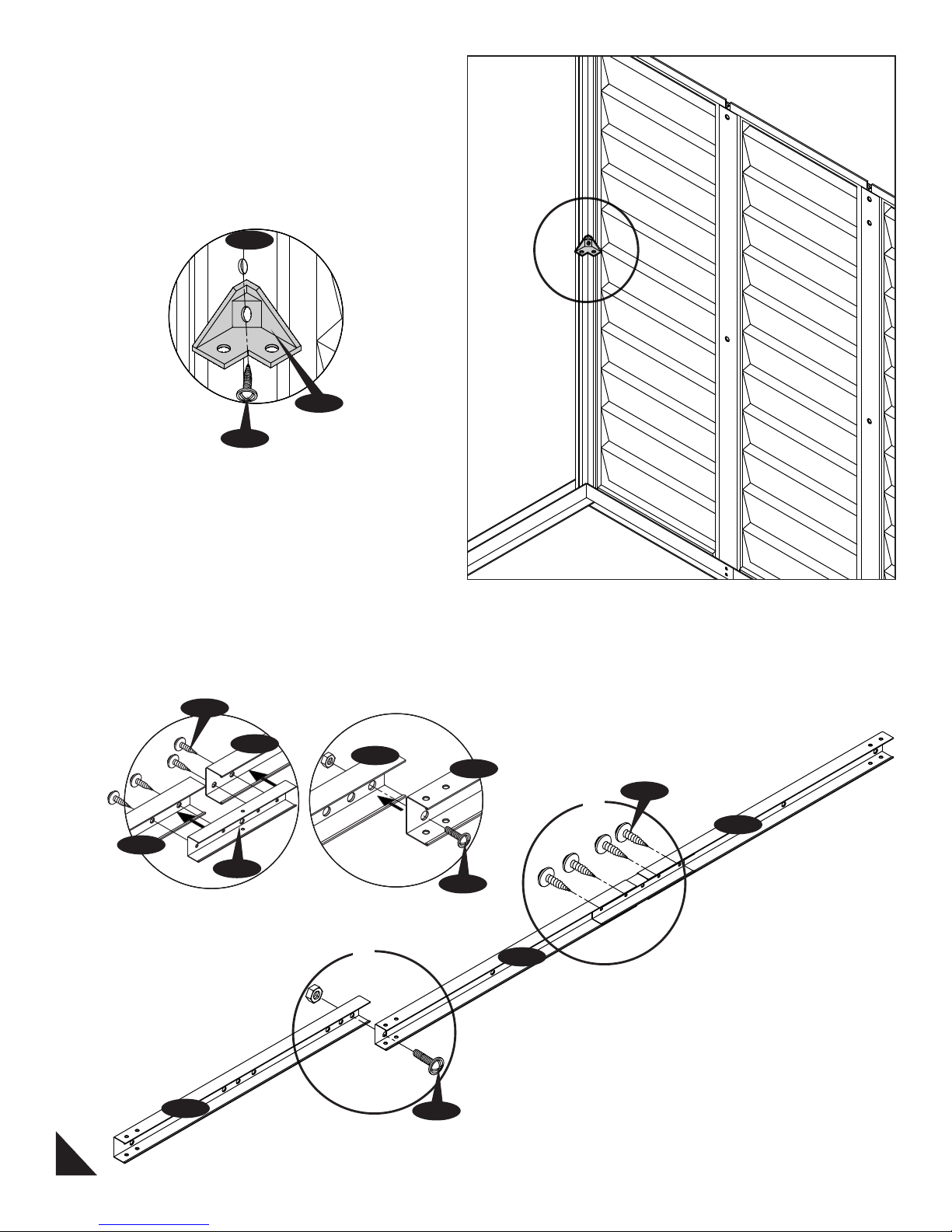
9. Fix the center band fitting (FCB) to the column
(CCA) with (S2) screw. Leave it loose.
CCA
FCB
S2
Back
10. Assemble the center bands (CB3XA) with
middle joining support (MJ) with (S1) Screws.
See fig.1. Assemble (CB3XA) & (CB3A) together
with (S1) screws. See fig.2.
S1
CB3XA
CB3XA
MJ
Fig.1
CB3A
Fig.2
2
CB3XA
S3
CB3XA
1
S1
CB3XA
CB3A
11
S3
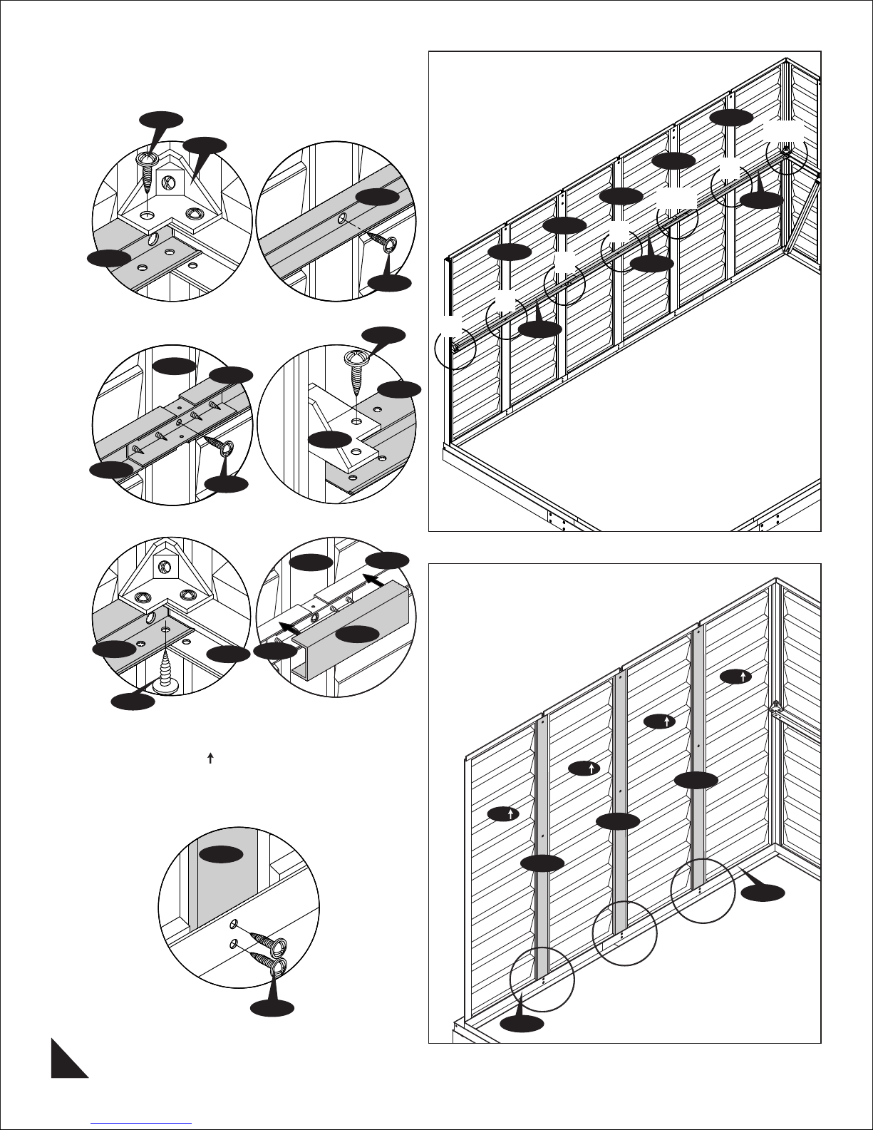
11. Stabilize the side panels with center bands
(CB3XA) & (CB3A) assembly. See fig.1 to 6 and
follow the steps.
S1
FCB
CMH
CMA
1&5
2
CB3XA
CB3XA
Fig.1
CMH
Fig.3
CB3XA
S1
CMH
Fig.2
FCB
Fig.4
CB3XA
S1
S1
CB3XA
CB3A
CMA
CMH
2
CMA
2
CB3XA
3&6
CB3XA
2
4
CB3A
CBC
CB3XA
CB1H
S1
Fig.5
CB3XA
Fig.6
12. Working from inside continue connecting the
3 side panels (SP
channel. Use (S1) screws to fix column to base.
) and columns to the base ‘U’
CMA
S1
SP
SP
SP
SP
CMA
CMA
CMA
B3LA
B3RA
12
 Loading...