

DuraMax Metal Garden Shed Owner's Manual/ Instructions For Assembly
TM
A Product of
ALL PURPOSE METAL STORAGE SHEDS
USP
US POLYMERS INC
Metal Garden Shed
OWNER’S MANUAL /
Instructions for Assembly
Size 6’ x 4’ with “Extension Kits”
• Tall Walk in Shed
• Quick & Easy Assembly
• Ridge Reinforced Walls
• Wide Double Doors
• Available in Various Sizes
Customer
Service Hotline
(800) 483-4674
www.uspolymersinc.com
PART 1
ASSEMBLING SHED WITH EXTENSION KIT
PART 2
ADDING EXTENSION KIT TO EXISTING SHED
Note: For shed with extension use this manual only.
Requires two people and takes 2-3 hours for Installation.
Call us for any missing or damaged parts.
Do not return to the store.

Duramax Storage Shed
Limited Fifteen Year Warranty
U.S. Polymer Inc. will send a replacement part free of charge, in the event of material defects and or
workmanship for a period of fifteen years from the date of purchase.
This warranty is extended only to the original purchaser. A purchase receipt or other proof of date of original
purchase will be required before warranty service is rendered. In no event shall we pay the cost of flooring,
labor, installation or any other costs related thereto.
This warranty only covers failures due to defects in material or workmanship which occurs during normal
use and does not extend to color change arising due to normal weathering or to damage resulting from
misuse or neglect, commercial use, failure to follow assembly instructions and the owner’s manual (including
proper anchoring of the shed), painting, forces of nature and other causes which is beyond our control.
Claims under this warranty must be made within the warranty period by calling 1-800-483-4674 or mail in
a dated sales slip and clear photograph of the part to:
U.S. Polymers, Inc.
6915 Slauson Avenue
Commerce, CA 90040
We reserve the right to discontinue or change components. If a component has been discontinued or is
not available,
U.S. Polymers, Inc. reserves the right to substitute a component of equal quality as may be compatible.
Limits and Exclusions
There are no express warranties except as listed above. The warrantor shall not be liable for incidental or
consequential damages resulting from the use of this product, or arising out of any breach of this warranty.
All express warranties are limited to the warranty period set forth above . Some states do not allow the
exclusion or limitation on how long an implied warranty lasts, so the above limitations may not apply to
you.
This warranty gives you specific legal rights and you may also have other rights which vary from state to
state or country to country.
Parts List
Note: Check all parts prior to installation.
CODE DESCRIPTION QTY
BLC BASE BAR BACK LEFT 1
BRC BASE BAR BACK RIGHT 1
BSC BASE BAR SIDE LEFT & RIGHT 2
BBFC BASE BAR FRONT LEFT & RIGHT 2
ECC ENTRANCE TAPER CHANNEL 1
DCLC DOOR COLUMN PROFILE LEFT 1
DCRC DOOR COLUMN PROFILE RIGHT 1
ABLC TOP ANGLE BACK LEFT 1
ABRC TOP ANGLE BACK RIGHT 1
ASC TOP ANGLE SIDE LEFT & RIGHT 2
SCC SLIDING CHANNEL COVER 1
SSB SLIDING CHANNEL SUPPORT 1
SLC SLIDING CHANNEL LEFT 1
SRC SLIDING CHANNEL RIGHT 1
RSC ROOF SUPPORT LEFT & RIGHT 2
RF1C ROOF FLASHING (FRONT RIGHT / BACK LEFT) 2
RF2C ROOF FLASHING (FRONT LEFT / BACK RIGHT) 2
RFSA ROOF FLASHING SIDE LEFT & RIGHT 2
RFCC ROOF FLASHING CENTER 1
TSLC DOOR PANEL STRIP TOP LEFT 1
TSRC DOOR PANEL STRIP TOP RIGHT 1
BDSC DOOR PANEL STRIP BOTTOM LEFT/RIGHT 2
DSSC DOOR PANEL STRIP SIDE LEFT & RIGHT 2
DSCC DOOR PANEL STRIP CROSS 4
WCFC WALL PANEL CORNER FRONT LEFT & RIGHT 2
WCBC WALL PANEL CORNER BACK LEFT & RIGHT 2
WSC WALL PANEL SIDE 3
WFLC WALL PANEL FRONT LEFT 1
WFRC WALL PANEL FRONT RIGHT 1
GPLC GABLE PANEL FRONT LEFT/BACK RIGHT 2
GPRC GABLE PANEL FRONT RIGHT/BACK LEFT 2
GPS GABLE PANEL SUPPORT 2
RP1C ROOF PANEL FRONT LEFT / BACK RIGHT 2
RP2C ROOF PANEL FRONT RIGHT/BACK LEFT 2
DPLC DOOR PANEL LEFT 1
DPRC DOOR PANEL RIGHT 1
ACCESSORIES
CODE DESCRIPTION QTY
BS BOTTOM SLIDER 4
DH DOOR HANDLE 2
FC FLASHING END CAP 2
TC TOP CORNER 4
TS TOP SLIDER 4
VC VENTILATION COVER 4
PW PLASTIC WASHER 134
PC PLASTIC SCREW COVER 86
WST WEATHER STRIPPING TAPE 2.00 mtr
S1 DIA. 4.2 x 10mm. (5/32” x 3/8”)
SHEET METAL SCREW 160
S2 DIA. 4.2 x 16mm. (5/32” x 5/8”)
SHEET METAL SCREW 22
S3 M4 x 16mm. (5/32” x 5/8”)
MACHINE SCREW W/ NUT 53
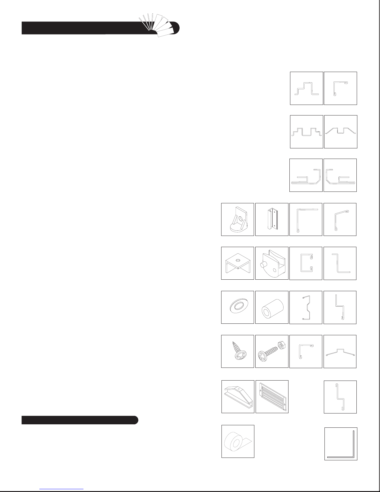
ACCESSORIES
BOTTOM SLIDER
(BS)
TOP CORNERS
(TC)
PLASTIC WASHER
(PW)
DOOR HANDLE
(DH)
TOP SLIDER
(TS)
PLASTIC SCREW COVER
(PC)
PROFILES
BASE BAR
(BLC, BRC, BSC)
BASE BAR
(BBFC)
DOOR COLUMN PROFILE
LEFT (DCLC)
SLIDING CHANNEL COVER
(SCC)
SLIDING CHANNEL
(SLC, SRC)
ROOF SUPPORT
(RSC)
TOP ANGLE BACK
(ABLC, ABRC)
ENTRANCE TAPER
CHANNEL (ECC)
DOOR COLUMN PROFILE
RIGHT (DCRC)
TOP ANGLE SIDE
(ASC)
SLIDING CHANNEL
SUPPORT (SSB)
DOOR PANEL STRIP SIDE
AND CROSS
(DSSC, DSCC)
Tools You Will Need
Hand Gloves
Cordless Drill - Philips Head
Screw driver - Philips Head
Carpenters Square
Eye Protector
IMPORTANT: USE HAND GLOVES TO PREVENT INJURY.
8’ Step Ladder
Adjustable pliers
Level - 3ft.
Tape Measure
SHEET METAL SCREW
(S1),(S2)
FLASHING END CAP
(FC)
WEATHER STIPPING TAPE
(WST)
MACHINE SCREW WITH
NUT (S3)
VENTILATION COVER
(VC)
ROOF FLASHING
(RF1C, RF2C)
ROOF FLASHING CENTER
(RFCC)
DOOR PANEL STRIP
TOP AND BOTTOM
(TSLC, TSRC, BDSC)
GABLE PANEL SUPPORT
(GPS)
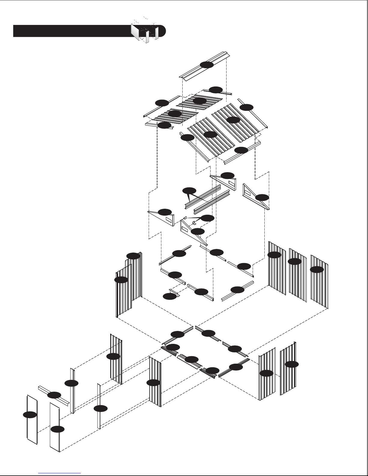
Exploded View
RFCC
RF1C
WCFC
WCBC
RFSA
RF2C
GPLC
RP1C
SSB
SLC
ASC
RF1C
RSC
RP2C
GPRC
SRC
RP2C
GPS
ABLC
RP1C
GPRC
RFSA
ASC
RF2C
ABRC
GPLC
WSC
WSC
WSC
WFLC
DCLC
SCC
DCRC
DPLC
DPRC
IMPORTANT: USE HAND GLOVES TO PREVENT INJURY.
WFRC
BSC
BBFC
ECC
BLC
BBFC
BRC
BSC
WCBC
WCFC

One Extension Parts List
Note: Check all parts prior to installation.
CODE DESCRIPTION QTY
EBS1 BASE BAR SIDE EXTENSION LEFT 1
EBS2 BASE BAR SIDE EXTENSION RIGHT 1
EAS1 TOP ANGLE SIDE EXTENSION LEFT 1
EAS2 TOP ANGLE SIDE EXTENSION RIGHT 1
ERS1 ROOF SUPPORT EXTENSION LEFT 1
ERS2 ROOF SUPPORT EXTENSION RIGHT 1
ERFS ROOF FLASHING SIDE EXTENSION LEFT/RIGHT 2
ERFC ROOF FLASHING CENTER EXTENSION 1
WSC WALL PANEL SIDE 2
RELC ROOF PANEL 1
RERC ROOF PANEL 1
ACCESSORIES
CODE DESCRIPTION QTY
PW PLASTIC WASHER 38
PC PLASTIC SCREW COVER 15
S1 DIA. 4.2 x 10mm. (5/32” x 3/8”)
SHEET METAL SCREW 40
S2 DIA. 4.2 x 16mm. (5/32” x 5/8”)
SHEET METAL SCREW 6
S3 M4 x 10mm. (5/32” x 3/8”)
MACHINE SCREW WITH NUT 6
WST WEATHER STRIPPING TAPE 1.5MTR
BASE BAR
(EBS1, EBS2)
ROOF SUPPORT
(ERS1, ERS2)
ACCESSORIES
PROFILES
TOP ANGLE SIDE
(EAS1, EAS2)
ROOF FLASHING SIDE
(ERFS)
ROOF FLASHING CENTER
(ERFC)
PLASTIC WASHER
(PW)
SHEET METAL SCREW
(S2)
WEATHER STRIPPING
TAPE
(WST)
PLASTIC SCREW COVER
(PC)
MACHINE SCREW WITH
NUT (S3)
IMPORTANT: USE HAND GLOVES TO PREVENT INJURY.
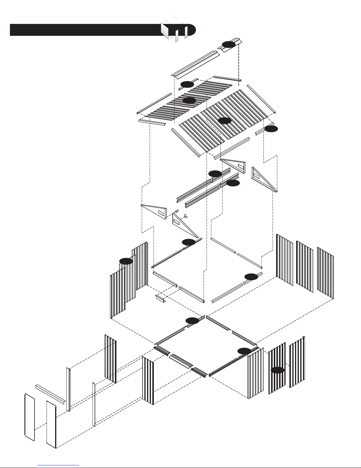
Exploded View with One Extension
ERFC
ERFS
RELC
RERC
ERFS
ERS1
ERS2
WSC
EAS1
EAS2
EBS1
EBS2
WSC
IMPORTANT: USE HAND GLOVES TO PREVENT INJURY.
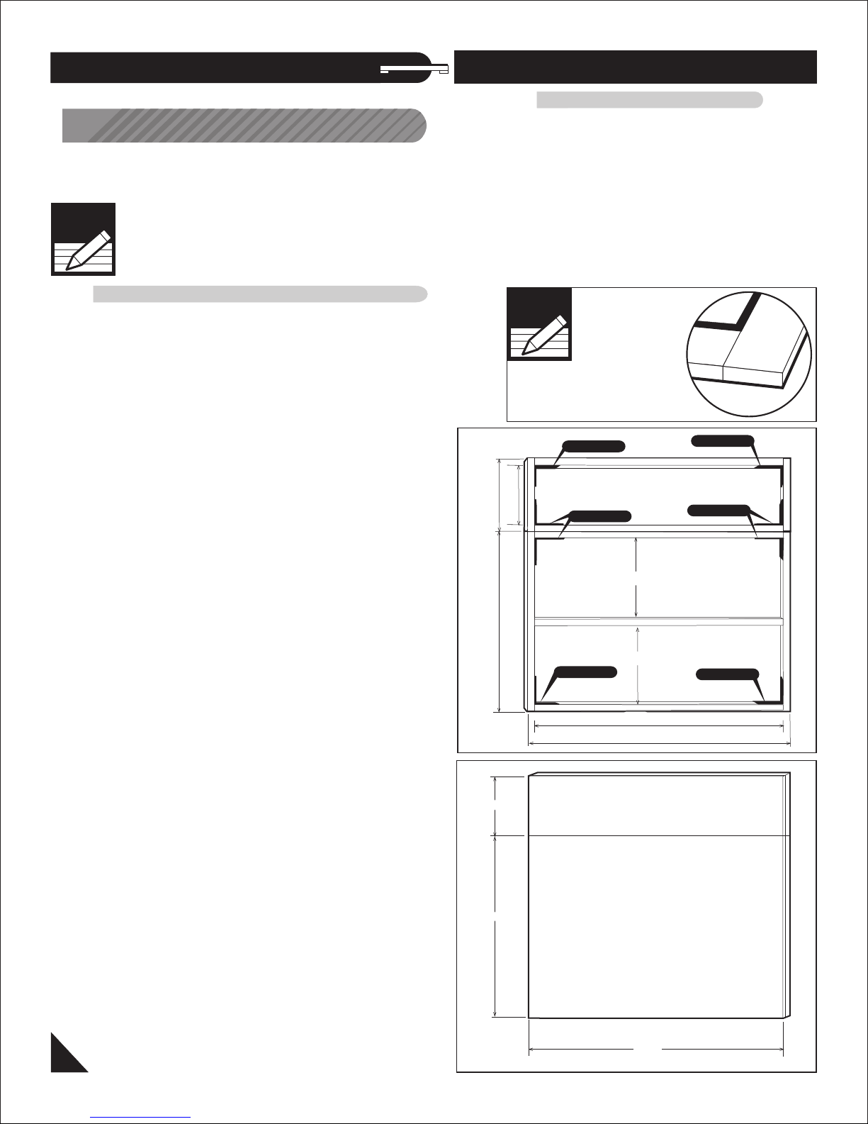
A. Foundation & Base Frame
Note: It is important that these instructions
are followed step by step.
DuraMax must be installed on a level wooden platform
or a level concrete foundation.
Note
Wooden platform is extra
and is not included.
Don’t install under
windy conditions.
Wooden Platform (each Extension) (Not Included)
The following are a list of lumber and sizes
you will need.
Pressure Treated - Wood Studs:
2ea 2” x 4” x 71” (50mm x 88.9mm x 1803.4 mm)
2ea 2” x 4” x 24” (50mm x 88.9mm x 609.6 mm)
Exterior Grade (CDX) - 3/4” (19mm) plywood
1ea 3/4” x 24” x 78” (19mm x 609.6mm x 1981.2mm)
L-Brackets: 4ea
PART 1: Assembling Shed With Extension Kit
Wooden Platform (Not Included)
The following are the list of lumber and sizes
you will need.
Pressure Treated - Wood Studs:
3ea 2” x 4” x 71” (50mm x 88.9mm x 1803.4mm)
2ea 2” x 4” x 47” (50mm x 88.9mm x 1193.8mm)
Exterior Grade (CDX) - 3/4” (19mm) plywood
1ea 3/4” x 47” x 78” (19mm x 1193.8mm x 1981.2mm)
L-Brackets: 4ea
Note
Lay 50 x 88.9mm Flat
L- BRACKET
L- BRACKET
Parts needed:
(1) Base bar back left (BLC)
(1) Base bar back right (BRC)
(2) Base bar side (BSC)
(2) Base bar front (BBFC)
(1) Entrance Taper channel (ECC)
(12) Sheet metal screw (S1)
(18) Sheet metal screw (S2)
Parts needed for each Extension:
(1) Base bar side extension left (EBS1)
(1) Base bar side extension right (EBS2)
(8) Sheet metal screw (S1)
(6) Sheet metal screw (S2)
1. Use pressure treated wood studs 2” x 4”
(50mm x 88.9mm) to create a platform frame that
has an outside dimension of 47” x 78”
(1193.8mm x 1981.2mm).
1a. Use pressure treated wood studs 2” x 4”
(50mm x 88.9mm) to create a platform frame that
has an outside dimension of 24” x 78”
(609.6mm x 1981.2mm) for each extension.
17” (431.8mm)
24” (609.6mm)
47” (1193.8mm)
24” (609.6mm)
L- BRACKET
L- BRACKET
L- BRACKET
18 1/4” (463.55mm)
18 1/4” (463.55mm)
L- BRACKET
71” (1803.4mm)
78” (1981.2mm)
OR 1b. Use pressure treated wood studs 2”x 4”
(50mm x 88.9mm) to create a platform frame that
has an outside dimension of 71”x 78”
(1803.4mm x 1981.2mm)
for shed one extension.
2. Using exterior grade CDX 3/4” (19mm) plywood,
cut and fit together the sheets to form solid foundation
as shown. Foundation must be square and level.
1
IMPORTANT: USE HAND GLOVES TO PREVENT INJURY.
47” (1993.8mm)
78” (1981.2mm)
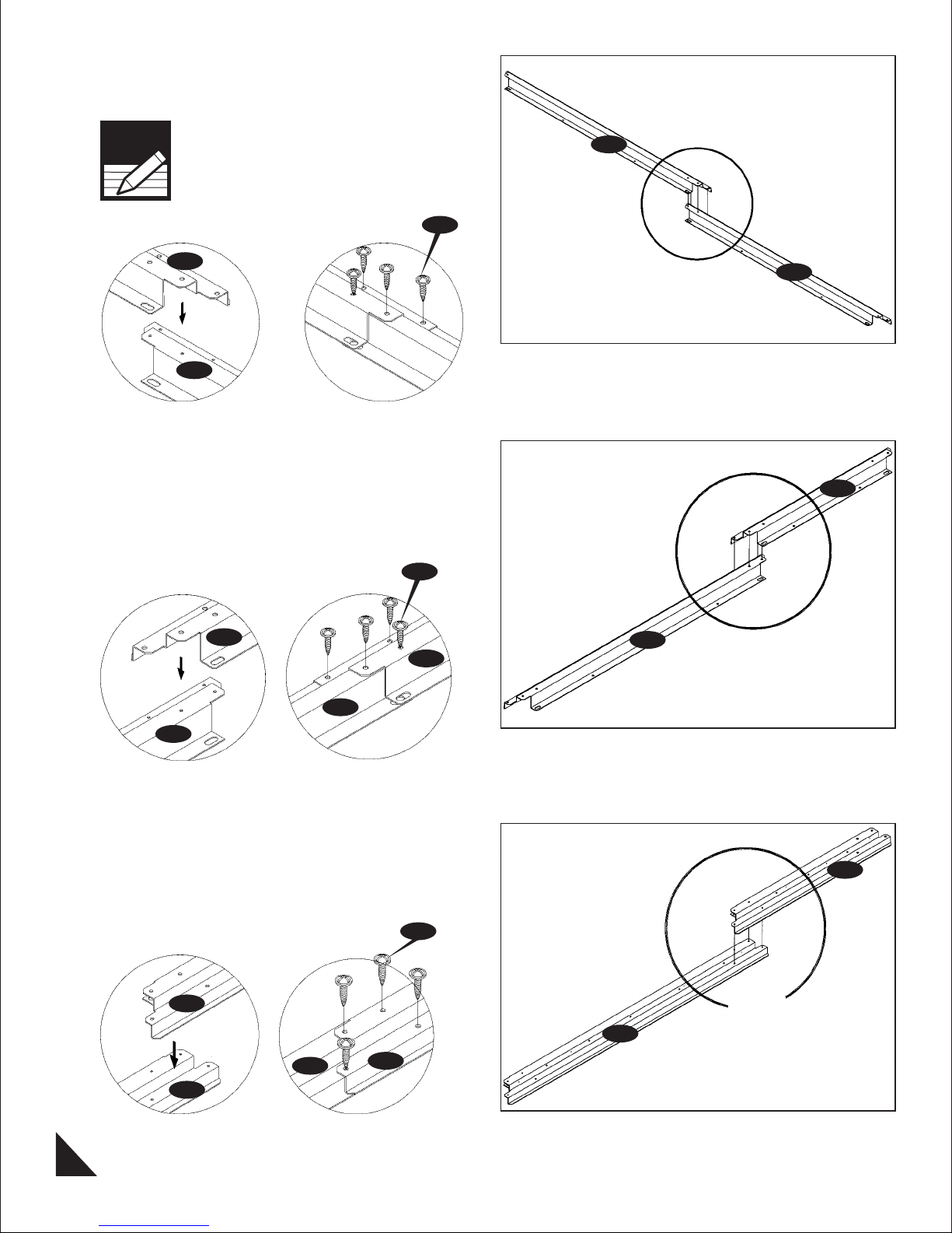
3. Assemble base bar back left (BLC) and base
bar back right (BRC) with four (S1) screws.
See fig. 1 & 2.
Note
Step 1
Take care of sharp edges.
Step 2
BLC
BRC
S1
Fig.1 Fig. 2
4. Assemble the base bar side (BSC) & extension
(EBS1) with (S1) screws.
Add one (EBS1) for each extension.
Step 1 Step 2
S1
BLC
1 & 2
BRC
EBS1
EBS1
EBS1
BSC
BSC
Fig.1 Fig. 2
5. Assemble the base bar side (BSC) & extension
(EBS2) with (S1) screws.
Add one (EBS2) for each extension.
Step 1 Step 2
EBS2
BSC
BSC
S1
EBS2
BSC
1 & 2
EBS2
1&2
BSC
Fig.1 Fig. 2
2
IMPORTANT: USE HAND GLOVES TO PREVENT INJURY.
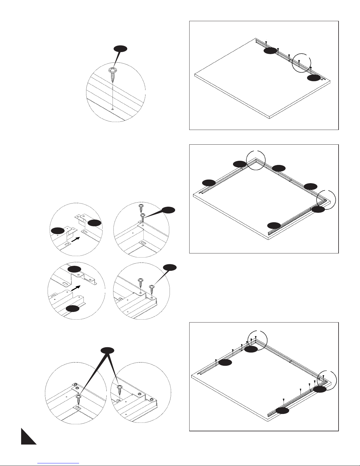
6. Place the base bar back assembly (BLC) &
(BRC) on top of the foundation. Use (S2) screws
to fix the assembly to foundation.
S2
Left
BLC
Back
1
BRC
Fig.1
7. Place the base bar left side assembly (BSC) &
(EBS1)on left side. Insert the edge of (EBS1) into
the back base bar (BLC) and secure with (S1)
screws. See fig. 1.
Place the base bar right side assembly (BSC) &
(EBS2) on right side. Insert the edge of (EBS2) into
the back base bar (BRC) and secure with (S1)
screws. See fig. 2.
Step 1
S1
BLC
EBS1
Fig.1
Step 2
BRC
S1
BSC
Front
EBS1
Right
1
BLC
BRC
BSC
2
EBS2
EBS2
Fig.2
8. Using a carpenter square, line up the corners
secure base bar side assembly to the foundation
with (S2) screws.
S2
Step 1
Fig.1
3
IMPORTANT: USE HAND GLOVES TO PREVENT INJURY.
Step 2
1
EBS1
BSC
2
EBS2
BSC
Fig. 2
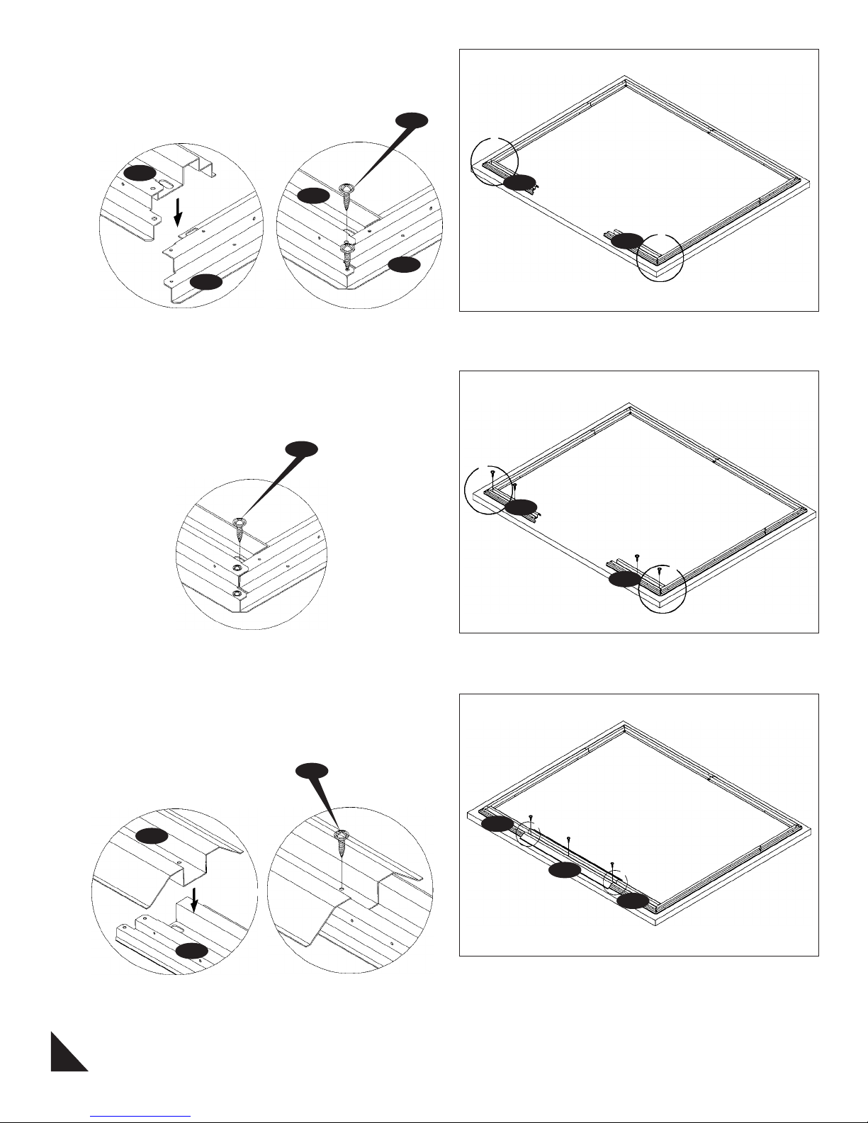
9. Place the base bar (BBFC) on top of (BSC) on
both sides. Secure with (S1) screw to (BSC) on
both corners. See fig. 1 & 2.
Step 1
BBFC
BSC
Step 2
BBFC
BSC
Fig.1 Fig.2
10. Using the carpenter square, line up the corners.
Secure the base (BBFC) to the foundation with (S2)
screws.
S2
S1
1&2
BBFC
1&2
BBFC
1
BBFC
Fig.1
11. Place the entrance taper channel (ECC) on
top of the (BBFC). Secure with (S2) screws to the
foundation. See fig. 1 & 2.
S2
Step 1
ECC
BBFC
Step 2
BBFC
1&2
ECC
BBFC
1
1&2
BBFC
Fig.1 Fig.2
4
IMPORTANT: USE HAND GLOVES TO PREVENT INJURY.

12. Measure in all direction as shown in figure.
Make the base bar assembly in a perfect square.
Concrete foundation
12a. (Concrete foundation) Using a carpenter’s
square, line up corners. Align Base bars, mark the
concrete at the holes in the base and drill concrete
with 1/4” (dia. 6mm) concrete bit to accept anchor
bolts to a 1 3/4” (44mm) depth. Replace base and
secure with 1/4” x 1 3/8” (M6 x 35mm) anchor bolts
(not provided).
B. Walls & Columns
BSC
BBFC
1560mm
(
(
ECC
EBS1
)
1830m
m)
BBFC
BLC
(
1830m
1560mm
(
BSC
m)
BRC
)
EBS2
Note
All panels are clearly marked
and care should be taken to
use the correct one.
Parts Needed:
(1) Wall panel front right (WFRC)
(1) Wall panel front left (WFLC)
(2) Wall panel corner front (WCFC)
(2) Wall panel corner back (WCBC)
(3) Wall panel side (WS)
(1) Sliding channel right (SRC)
(1) Sliding channel left (SLC)
Parts Needed for each extension:
(2) Wall panel (WSC)
(1) Top angle side extension left (EAS1)
(1) Top angle side extension right (EAS2)
(15) Plastic washer (PW)
(16) Sheet metal screw (S1)
(2) Machine screw (S3)
1. Place the wall panel (WFRC) on the base bar
(BBFC). Front right side of the shed line up the holes
with base bar. Secure with (S1) screws with washers
from outside.
(2) Top angle side (ASC)
(1) Sliding channel support (SSC)
(1) Sliding channel cover (SCC)
(4) Top slider (TS)
(1) Door column profile left (DCLC)
(1) Door column profile right (DCRC)
(1) Top angle back left (ABLC)
(1) Top angle back right (ABRC)
(54) Plastic washer (PW)
(64) Sheet metal screw (S1)
(8) Machine screw (S3)
PW
S1
WFRC
BBFC
Fig.1
5
IMPORTANT: USE HAND GLOVES TO PREVENT INJURY.
WFRC
1
Front
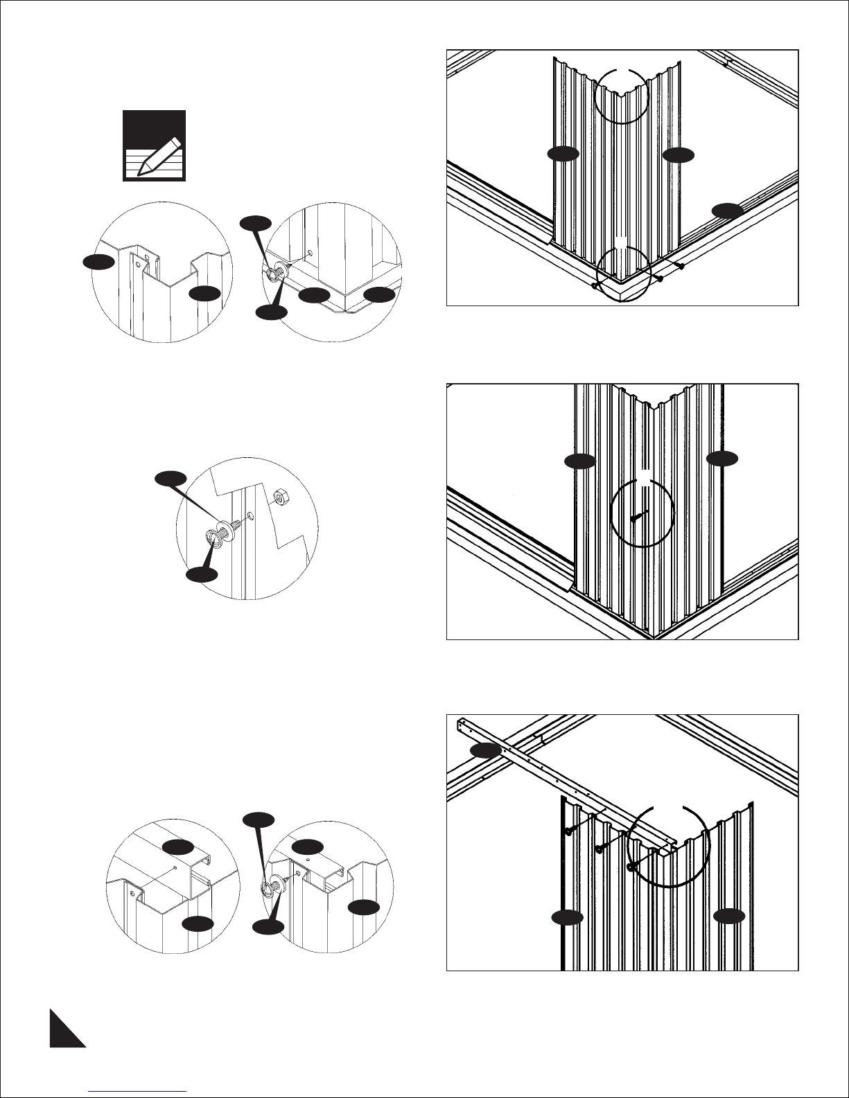
2. Place the wall panel corner front (WCFC) on the
base bar (BSC). Line up the holes with base bar and
use (S1) screws with washers to Secure.
1
Note
WFRC
Make sure the overlapping
position is as shown in fig.1.
S1
WCFC
BBFC
PW
BSC
Fig.1 Fig.2
3. Use (S3) bolt and nut with washer to join together
the wall panels.
PW
WFRC
WFRC
WCFC
BSC
2
WCFC
1
S3
Fig.1
4. Place the sliding channel right (SRC) on top of
the wall panel (WFRC) from inside. See the position
in fig. 1. Line up the holes with wall panel. Use (S1)
screw with washers to fix. See fig. 2.
S1
SRC
WCFC
Fig.1 Fig.2
SRC
WCFC
PW
SRC
WFRC
1&2
WCFC
6
IMPORTANT: USE HAND GLOVES TO PREVENT INJURY.
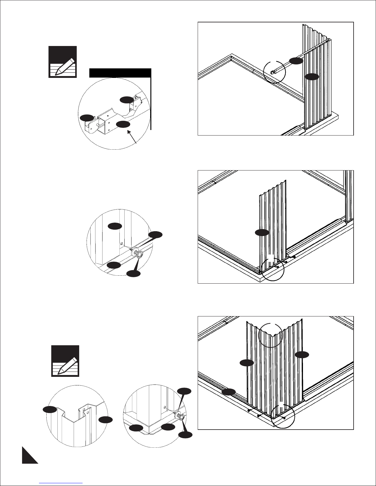
5. Insert the 2 pieces of (TS) Top slider into the
sliding channel. See blowup.
Note
Make sure the position of the
projection on (TS) towards
inside.
TS
TS
SRC
Front
Fig.1
6. Place the wall panel (WFLC) on the base bar
(BBFC). Front left side of the shed. Line up to holes
with base bar. Secure with (S1) screws with washers
from outside.
WFLC
PW
WFLC
1
SRC
WFRC
BBFC
S1
Fig.1
7. Place the wall panel corner front (WCFC) on the
base bar (BSC). Line up the holes with base bar
and use (S1) screws with washers to secure.
Note
WCFC
Make sure the overlapping
position is as shown in fig.1
WFLC
BSC
BBFC
PW
S1
1
Front
1
WFLC
WCFC
BSC
2
7
Fig.1 Fig.2
IMPORTANT: USE HAND GLOVES TO PREVENT INJURY.
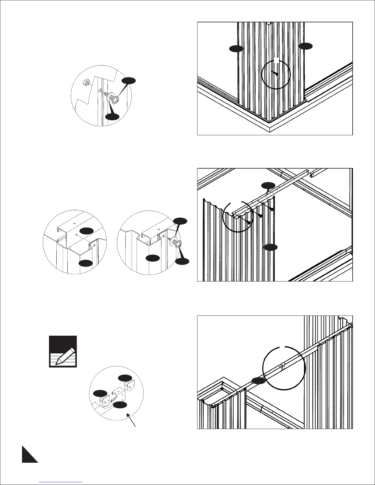
8. Use (S3) bolt and nut with washer to join together
the wall panels.
S3
PW
Fig.1
9. Place the sliding channel left (SLC) on top of the
wall panel (WFLC) from inside. See the position in
fig1. Line up the holes with wall panel use (S1) screw
with washers to fix. See fig. 2
SLC
PW
WCFC
1&2
WFLC
1
SLC
WFLC
WFLC
Fig.1 Fig.2
10. Insert the 2 pieces of (TS) Top slider into the
sliding channel. See blowup.
Note
Make sure the position of the
projection on top slider towards
inside.
TS
TS
SLC
WFLC
S1
1
SLC
Fig.1
8
IMPORTANT: USE HAND GLOVES TO PREVENT INJURY.
Front
 Loading...