

DuraMax Insulated Cabin Owner's Manual/ Instructions For Assembly
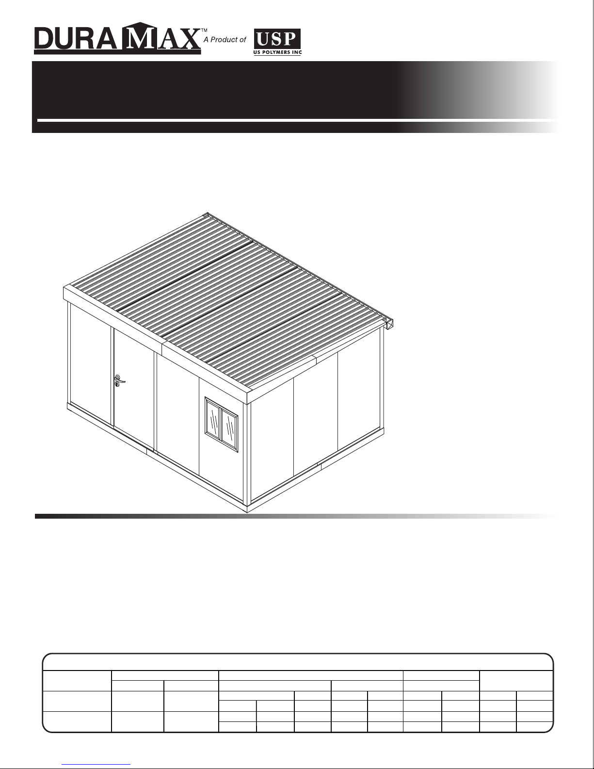
ALL PURPOSE INSULATED CABINS
Insulated Cabin
OWNER’S MANUAL /
Instr
uctions for Assembly
Size 10 Ft x 13 Ft / 3.1 Mtr
Ver. : 2.0
. x 4.0 Mtr
. (Approx.)
Customer
Service Hotline
• Strong & Secure Cabin
• Quick & Easy Assembly
• Metal Cladded Insulated Walls
• Wide Door with Lock
• Easily Expandable
Available Kits
• Modular Extension Kits Available
• Window Kits Available
Approximate
Size
10 Ft x 13 Ft
3.1 Mtr. x 4.0 Mtr.
129 Sq. Ft.
Storage
Area Volume
12 Sq.Mtr.
878 Cu.Ft.
24.9 Cu.Mtr.
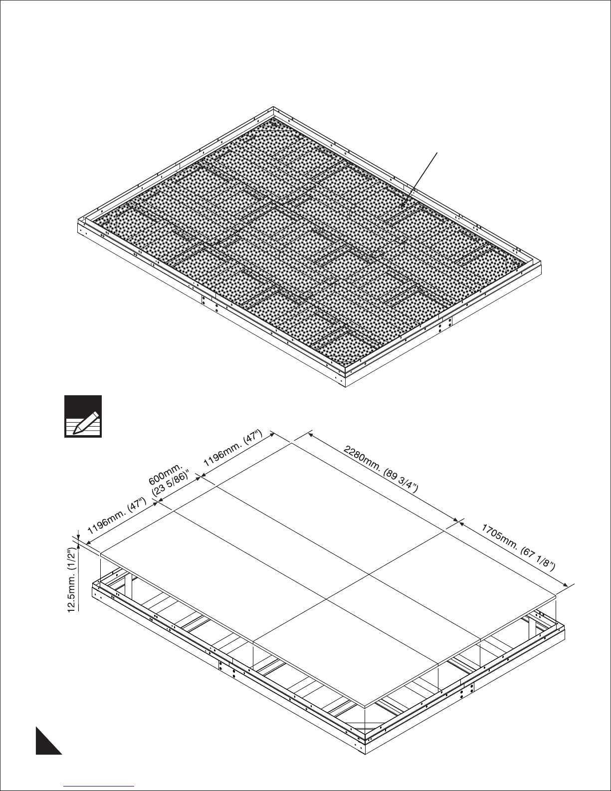
Building Dimensions :
Exterior Dimension Interior Dimension
Base Dimension
Width
Depth
Height
inch cm.
159 1/4 404.5
120 1/4
305.4
(800) 483-4674
www.uspolymersinc.com
Requires two people and takes 4-5 hours for Installation.
Roof Edge to Edge
inch cm.
161
125 1/4
90
409
318
228.6
Call us for any missing or damaged parts.
Wall to Wall
inch cm.
157 1/8
118 1/8
81 3/4
Do not return to the store.
Door Opening
inch
399
300
208
37 1/4
82 3/4
cm.
95
210

Duramax Insulated Shed
Limited Seven Year Warranty
U
.S. Polymer Inc. will send a replacement part free of charge, in the event of material defects and or
workmanship for a period of seven years from the date of purchase.
This warranty is extended only to the original purchaser. A purchase receipt or other proof of date of original
purchase will be required before warranty service is rendered. In no event shall we pay the cost of flooring,
labor, installation or any other costs related thereto.
This warranty only covers failures due to defects in material or workmanship which occurs during normal
use and does not extend to color change arising due to normal weathering or to damage resulting from
misuse or neglect, commercial use, failure to follow assembly instructions and the owner’s manual (including
proper anchoring of the shed), painting, forces of nature and other causes which is beyond our control.
Claims under this warranty must be made within the warranty period by calling 1-800-483-4674 or mail in
a dated sales slip and clear photograph of the part to:
U.S. Polymers, Inc.
1057 S. Vail Ave,
Montebello, CA 90640.
We reserve the right to discontinue or change components. If a component has been discontinued or is
not available,
U.S. Polymers, Inc. reserves the right to substitute a component of equal quality as may be compatible.
Limits and Exclusions
There are no express warranties except as listed above. The warrantor shall not be liable for incidental or
consequential damages resulting from the use of this product, or
All express warranties are limited to the warranty period set forth above . Some states do not allow the
exclusion or limitation on how long an implied warranty lasts, so the above limitations may not apply to
you.
This warranty gives you specific legal rights and you may also have other rights which vary from state to
state or country to country
.
arising out of any breach of this warranty.
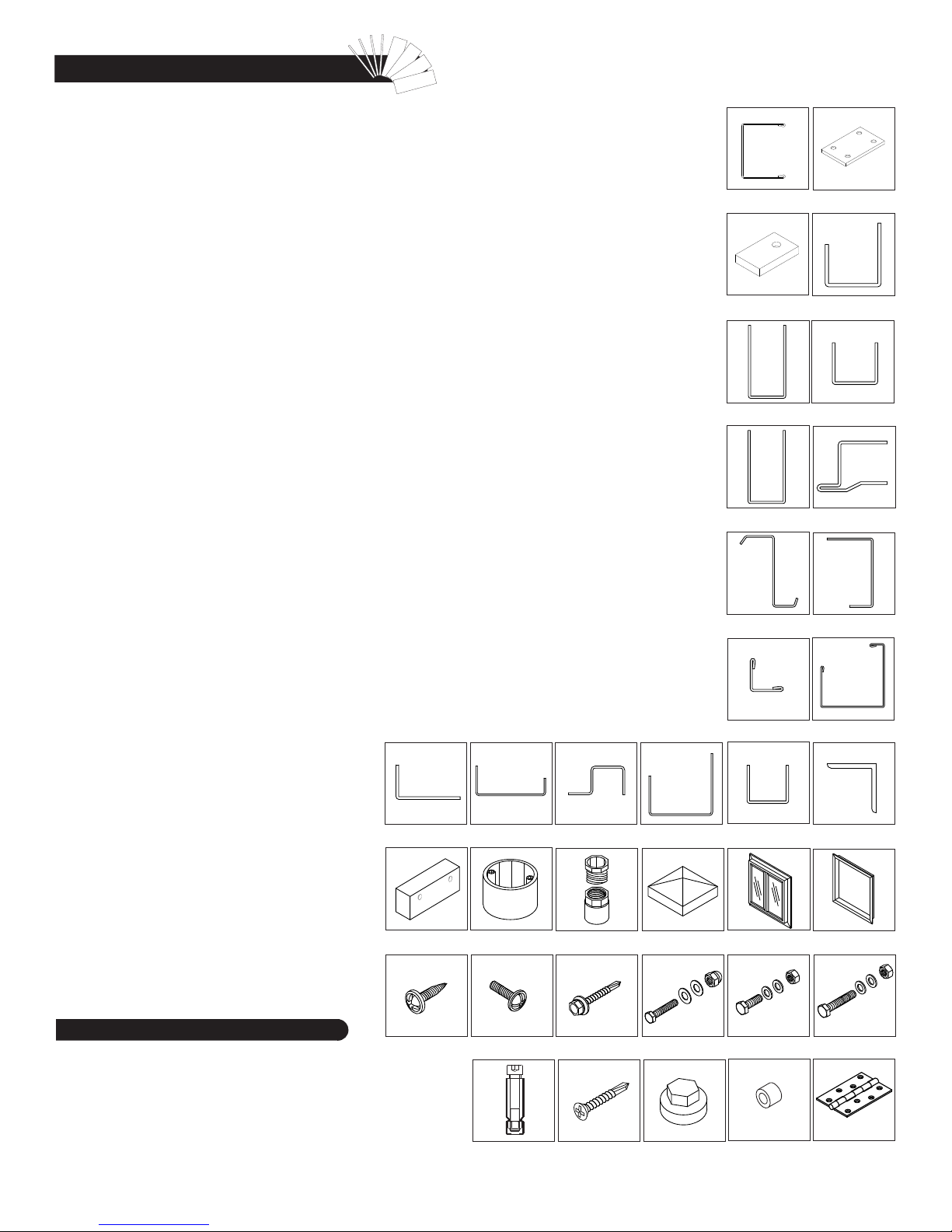
Parts List
Note: Check all parts prior to installation.
CODE DESCRIPTION QTY
PROFILES
CODE DESCRIPTION QTY
F1C FOUNDA
TION ‘U’ CHANNEL 2
F2C FOUNDATION ‘U’ CHANNEL 2
F3C FOUNDATION ‘U’ CHANNEL 4
F4C FOUNDATION ‘U’ CHANNEL 4
F5C FOUNDA
TION ‘U’ CHANNEL 2
F6C FOUNDATION ‘U’ CHANNEL 2
F7C FOUNDATION ‘U’ CHANNEL 4
F8C FOUNDATION ‘U’ CHANNEL 18
F9C FOUNDATION ‘U’ CHANNEL 4
F10C FOUNDATION ‘U’ CHANNEL JOINT 8
F11C FOUNDATION ANCHOR 8
BC1C BASE ‘U’ CHANNEL FRONT LEFT / BACK RIGHT 2
BC2C BASE ‘U’ CHANNEL FRONT RIGHT / BACK LEFT 2
BC3C BASE ‘U’ CHANNEL SIDE 2
BC4C BASE ‘U’ CHANNEL SIDE 2
TC1C TOP ‘U’ CHANNEL FRONT LEFT 1
TC2C TOP ‘U’ CHANNEL FRONT RIGHT 1
TC3C TOP ‘U’ CHANNEL BACK LEFT 1
TC4C TOP ‘U’ CHANNEL BACK RIGHT 1
TC5C TOP ‘U’ CHANNEL RIGHT SIDE FRONT 1
TC6C TOP ‘U’ CHANNEL RIGHT SIDE BACK 1
TC7C TOP ‘U’ CHANNEL LEFT SIDE FRONT 1
TC8C TOP ‘U’ CHANNEL LEFT SIDE BACK 1
DCLC DOOR COLUMN LEFT 1
DCRC DOOR COLUMN RIGHT 1
DSC DOOR STOPPER TOP / BOTTOM 2
CC CORNER COVER 4
RSC ROOF PANEL SUPPORT 3
RF1C ROOF FLASHING FRONT LEFT 1
RF2C ROOF FLASHING FRONT RIGHT 1
RF3C ROOF FLASHING RIGHT SIDE FRONT 1
RF4C ROOF FLASHING RIGHT SIDE BACK 1
RF5C ROOF FLASHING LEFT SIDE FRONT 1
RF6C ROOF FLASHING LEFT SIDE BACK 1
RF7C ROOF FLASHING SUPPORT 9
GL
GR
GUTTER LEFT 1
C GUTTER RIGHT 1
GJC GUTTER JOINT 1
TS1C SIDE TOP CHANNEL SUPPORT FRONT 2
TS2C SIDE TOP CHANNEL SUPPORT BACK 2
PC1C PIPE BRACKET 1
PC2C PIPE CLAMP 1
GSC GUTTER SUPPORT 4
RSJC ROOF PANEL SUPPORT JOINT 6
TS3C FRONT TOP CHANNEL SUPPORT BLOCK 3
DCV4 DRAINAGE PIPE 1
W1C WALL PANEL 10
W2C WALL PANEL FRONT LEFT 1
W3C
WALL PANEL FRONT RIGHT 1
W4C WINDOW CUT WALL PANEL 1
R1C ROOF PANEL RIGHT 1
R2C ROOF PANEL CENTER 2
R3 ROOF PANEL LEFT 1
DOOR
DOOR 1
WINDOW 1
WINDOW FRAME 1
ACCESSORIES
CODE DESCRIPTION QTY
DNS NO SPOUT BOX 1
DF
A4 FEMALE ADAPTOR 1
P2BE P2 BEVEL END CAP 2
S1 DIA. 4.2 x 16mm SHEET METAL SCREW 288
S2 DIA. 4.2 x 32mm SHEET METAL SCREW 4
S3 M4x10mm MACHINE SCREW 2
S10 DIA. 6.2 x 60mm SELF DRILLING SCREW
42
S11 M4x35mm. HEX. BOLT & DOMED CAP NUT 52
S12 M6x15mm. HEX. BOLT & NUT 12
S13 M6x40mm. HEX. BOLT & NUT 12
S14 ANCHOR BOLT 8
S15 DIA. 4.2 x 16mm SELF DRILLING SCREW 24
S16 HEX. SCREW CAP 42
S17 M4x30mm. HEX. BOLT & DOMED CAP NUT 8
S18 M4x35mm. HEX. BOLT & NUT 8
S19 PLASTIC SCREW COVER 8
HC HINGES 3
SILICON CLEAR 2
DOOR LOCK WITH SCREWS 1
SUPER GLUE 1
GSC
TS3C
PC1C
DNS
PC2C
DFA4 P2BE
GJC
F1C, F2C, F3C, F4C, F5C,
F6C, F7C, F8C, F9C
F11C
TC1C, TC2C,
TC5C, TC6C
TC7C, TC8C
RSC
RF7C
TS1C, TS2C
WINDOW WINDOW FRAME
DCLC, DCRC, DSC
RF1C, RF2C, RF3C
RF4C, RF5C, RF6C
F10C
BC1C, BC2C
BC3C, BC4C
TC3C, TC4C
GLC, GRC
RSJC
Tools You Will Need
Hand Gloves
Cordless Drill - Philips Head
Screw driver - Philips Head
Carpenter’s Square
Eye Protector
8’ Step Ladder
Adjustable pliers
Level - 3ft.
Tape Measure
Hammer or Rubber Mallet
Caulk Gun
10mm Hex. Socket Bit
7.0mm Spanner
IMPORTANT : USE HAND GLOVES TO PREVENT INJURY.
S1, S2
S3
S14
S10
S15
S11, S17
S16
S12
S19
S13, S18
HC
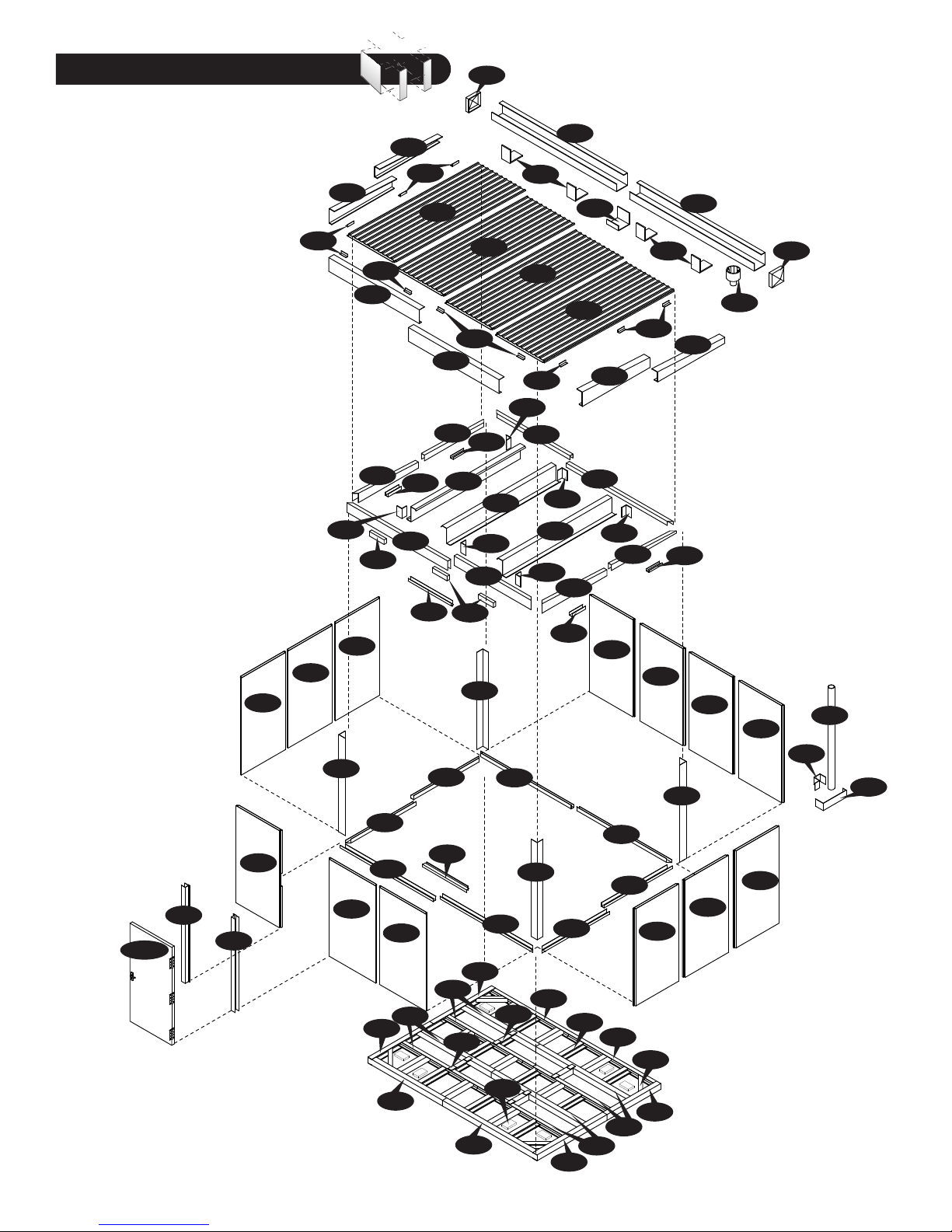
Exploded View
P2BE
W1C
RF7C
W1C
RF5C
RSJC
W1C
CC
RF7C
RF1C
TC7C
TS3C
RF6C
TS1C
TC1C
RF7C
DSC
R3C
BC4C
RF2C
TC8C
RF7C
RSC
TS3C
R2C
TS2C
RSJC
TC2C
CC
RSC
RSJC
BC2C
GSC
R2C
RF7C
TC3C
RSJC
RSJC
RSC
GLC
TC5C
TS1C
R1C
GJC
TC4C
RF3C
RSJC
W1C
TC6C
RF7C
W1C
GSC
RF4C
TS2C
CC
GRC
W1C
P2BE
DNS
DCV4
W1C
PC2C
PC1C
W2C
DCLC
DOOR
DCRC
IMPORTANT : USE HAND GLOVES TO PREVENT INJURY.
W3C
BC3C
BC1C
F5C
F1C
W1C
F3C
DSC
F3C
F10C
F6C
F2C
BC2C
F11C
F9C
CC
F2C
BC4C
F6C
F8C
F4C
BC1C
BC3C
F1C
F4C
W1C
W1C
W1C
F7C
F5C
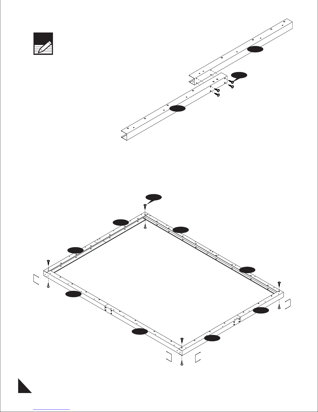
A. Foundation & Base Assembly
Note: It is important that these instructions
are followed step by step.
Note
CODE QTY
F1C 2
F2C 2
F3C 4
F4C 4
F5C 2
F6C 2
F7C 4
F8C 18
F9C 4
All parts are clearly marked and care should
be taken to use the correct one.
Before Assembling Foundation make sure
that the floor level should be perfect flat.
Step - 1
Note
Make Two sets
Parts needed:
CODE QTY
F10C 8
F11C 8
BC1C 2
BC2C 2
BC3C 2
BC4C 2
S1 160
S14 8
F1C
Step - 2
Note
Make Four sets
S1
F2C
F3C
S1
F4C
1
IMPORTANT : USE HAND GLOVES TO PREVENT INJURY.
Step - 3
Note
Make Two sets
F5C
S1
F6C
Step - 4
S1
F6C
F2C
F5C
F1C
F1C
F5C
F2C
F6C
2
IMPORTANT : USE HAND GLOVES TO PREVENT INJURY.
Step - 5
S1
Step - 6
F7C
F1C
F5C
F6C
F7C
F2C
F2C
F1C
F7C
F5C
F7C
F6C
F3C
3
IMPORTANT : USE HAND GLOVES TO PREVENT INJURY.
F3C
F3C
F3C
F4C
F4C
F4C
F4C
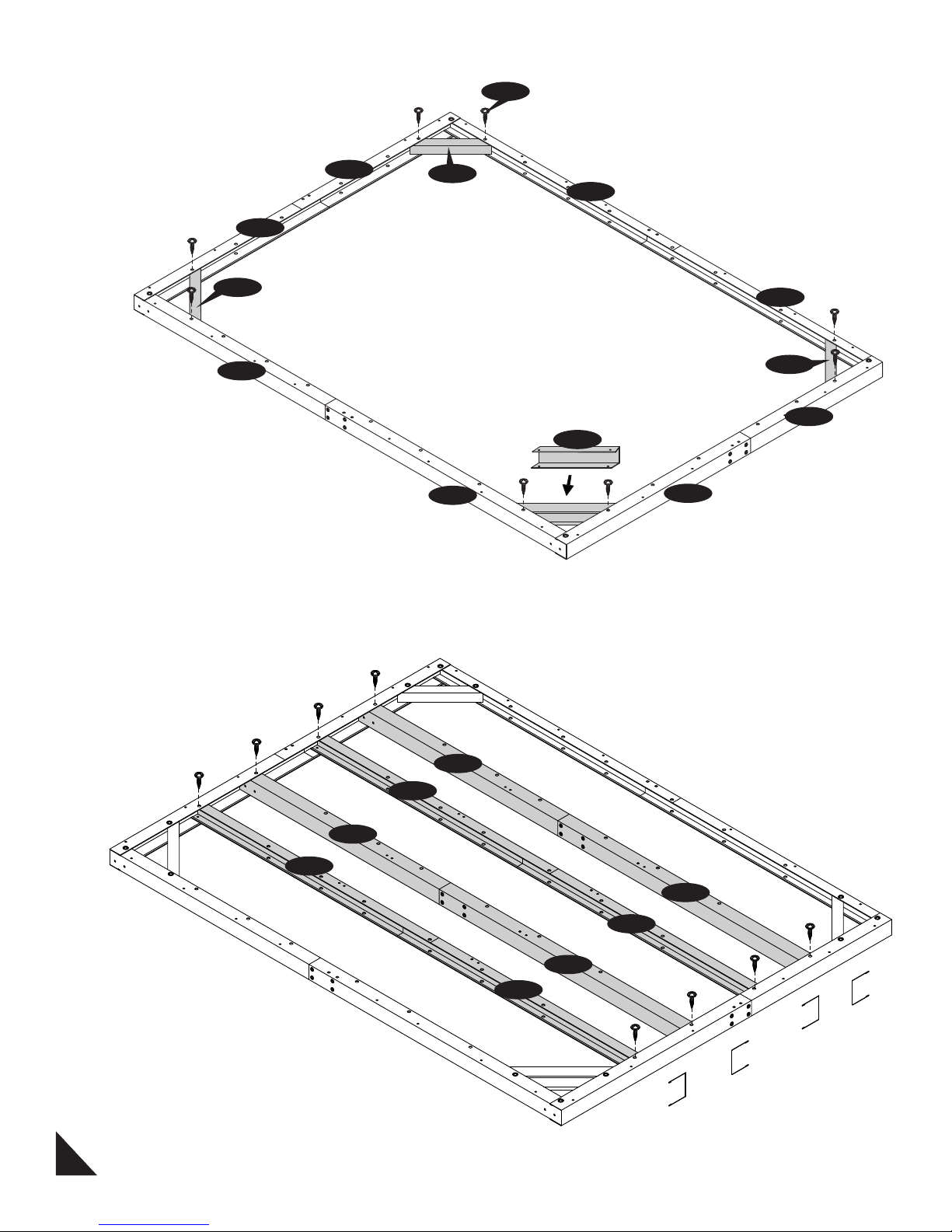
Step - 7
S1
F8C
F8C
F8C
Step - 8
F10C
S1
F9C
F9C
F9C
F9C
S1
F10C
F9C
F9C
4
IMPORTANT : USE HAND GLOVES TO PREVENT INJURY.
Step - 9
F2C
F1C
F1C
F2C
F1C
S14
Step - 10
1
F1C
F11C
BC3C
LEFT
BC1C
FRONT
BC4C
BC2C
F2C
BC2C
BACK
BC1C
BC3C
F5C
BC4C
S1
BC1C
F1C
Fig. 1
5
IMPORTANT : USE HAND GLOVES TO PREVENT INJURY.
F2C
S1
Fig. 2
F2C
BC2C
RIGHT
F6C
2
Step - 11
Option - 1
After assemble the Base ‘U’ Channel it can be
filled with concrete up to the Foundation level.
Concrete
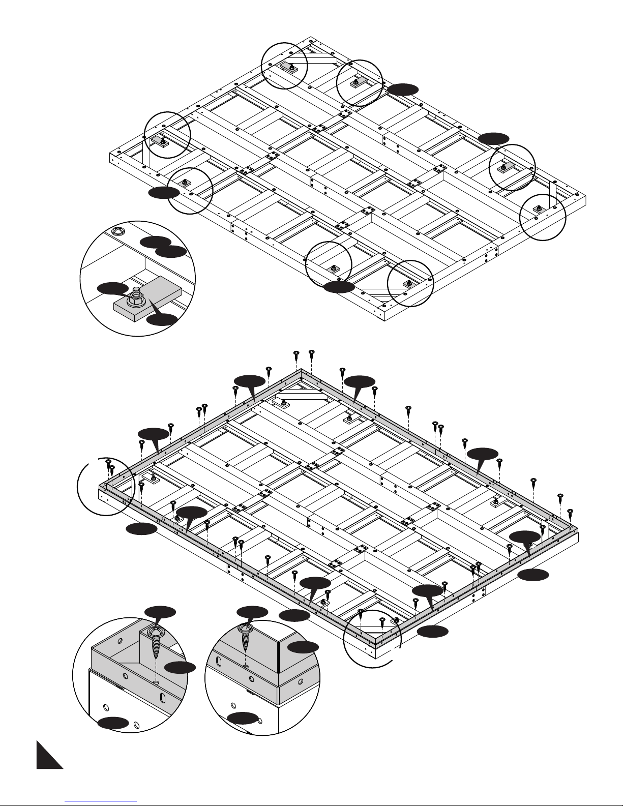
Option - 2
The Plywood can be placed by this sizes inside
the base ‘U’ Channel.
Note
The Plywood should be placed after
completing the Wall Panel Assembly.
6
IMPORTANT : USE HAND GLOVES TO PREVENT INJURY.
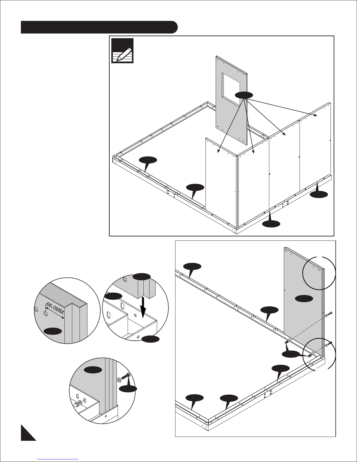
B. Wall Assembly
Parts needed:
CODE QTY
W1C 10
W2C 1
W3C 1
W4C 1
TC1C 1
TC2C 1
TC3C 1
TC4C 1
TC5C 1
TC6C 1
TC7C 1
TC8C 1
CC 4
DCRC 1
DCLC 1
DSC 2
TS1C 2
TS2C 2
TS3C 3
RSC 3
RSJC 6
S1 46
S11 52
S12 12
S13 12
S17 8
S18 8
S19 8
Note
This Insulated Cabin included with one
Window Panel (W4C) . This can be fix Four
position as shown.
W4C
LEFT
BC1C
BC2C
FRONT
BACK
BC3C
RIGHT
BC4C
Step - 1
W1C
Fig. 1
W1C
BC1C
S11
W1C
Fig. 2
BC3C
BC2C
BC2C
BC4C
BACK
BC1C
RIGHT
BC3C
S11
W1C
W1C
1
2&3
7
Fig. 3
IMPORTANT : USE HAND GLOVES TO PREVENT INJURY.
FRONT
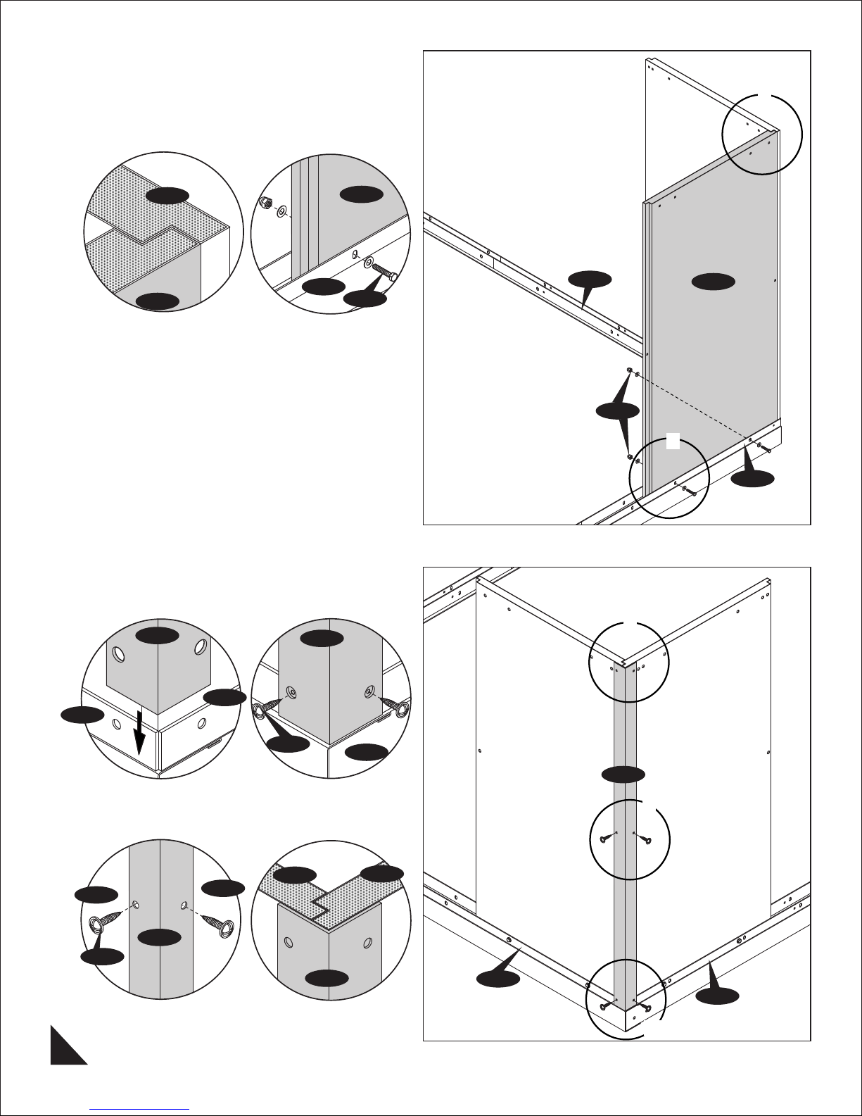
Step - 2
1
W1C
Fig. 1 Fig. 2
Step - 3
W1C
BC3C
W1C
S11
BACK
BC1C
W1C
S11
2
BC3C
RIGHT
BC3C
W1C
S1
CC
BC1C
CC
S1
Fig. 1 Fig. 2
W1C
CC
W1C
CC
Fig. 3 Fig. 4
BC1C
W1C
BC3C
RIGHT
CC
4
3
BC1C
BACK
1&2
8
IMPORTANT : USE HAND GLOVES TO PREVENT INJURY.
 Loading...