

DuraMax BiTurbo T2, Jr. HT, Duo, Trio, BiTurboT R C Use & Care Manual
...
Use & Care Guide
Robotic Pool Cleaning System
DuraMax
DuraMax Jr. HT
DuraMax Jr. T RC
DuraMax
DuraMax
DuraMax Bi-Turbo T RC
DuraMax Bi-Turbo T2
DuraMax RC
DuraMax Duo Jr.
DuraMax Duo
DuraMax Trio
DuraMax DuraMax
.
820319
IMPORTANT INFORMATION
DuraMAX
Jr. HT
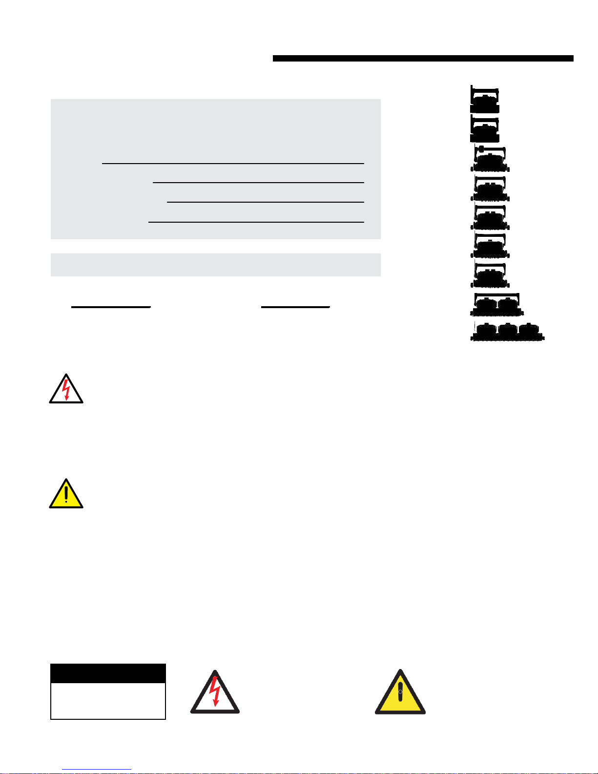
MAKE A RECORD FOR FUTURE USE
Model
Purchase Date
Place Purchased
Serial Number
Note: Serial number can be found on the warrantee card or on the packing carton.
QUESTIONS
1-888-AQUATECH (888-278-2832)
For Technical Support
FAX: 973-857-0261
Before performing any troubleshooting or maintenance procedures on your cleaner, it should be
disconnected from the Power Supply (transformer) and the Power Supply should be unplugged from the
electrical outlet to prevent the possibility of personal injury or damage to the cleaner.
?
INTERNET
For online support and product information
visit www.AquaProducts.com/Service
DuraMAX
Jr. T RC
DuraMAX
DuraMAX
o
BiTurb
R C
T
DuraMAX
BiTurbo T2
DuraMAX
RC
DuraMAX
Duo Jr.
DuraMAX
Duo
DuraMAX
Trio
Always Unplug your Power Supply when not in use to prevent accidental starts.
Never operate the cleaner out of the water. Doing so will cause severe damage to the motor and void the
product Warranty.
Water temperature and chemical composition changes can greatly affect the buoyancy of your cleaner.
Therefore, if you have previously installed floatation devices in your cleaner to assist its buoyancy, it may
be necessary to remove the devices one by-one until proper buoyancy is restored.
Never lift your cleaner out of the pool using the Floating Cable. You may use the Floating Cable to pull the
cleaner to the side of the pool, but always use the Floating Handle to remove it from the pool. Pulling on the
Floating Cable to remove the cleaner from the pool will result in internal connections being broken and
severe damage being caused to your cleaner.
Please Read The Entire Manual Carefully Before
Using Your Automatic Commercial Pool Cleaner
CAUTION
RISK OF ELECTRIC SHOCK
DO NOT REMOVE TRANSFORMER
COVER. NO USER-SERVICABLE
PARTS INSIDE.
Never Swim While Cleaner Is In Use
This symbol is intended to alert the
This symbol is intended to alert the
u s er t o t h e p r es en c e o f
u s er t o t h e p r es en c e o f
“dangerous voltage” within the
“dangerous voltage” within the
product’s enclosure that may be of
product’s enclosure that may be of
sufficient magnitude to constitute a
sufficient magnitude to constitute a
risk of electric shock to persons.
risk of electric shock to persons.
This symbol is intended to alert the
user to the presence of
o p e r a t i n g a n d m a i n te n a n c e
(s erv icing ) i nstru cti ons i n t he
li t e r a t u re a cc o m p a n y in g th e
appliance.
important
2
Robotic Commercial Pool Cleaner
For Commercial - Public Swimming Pools
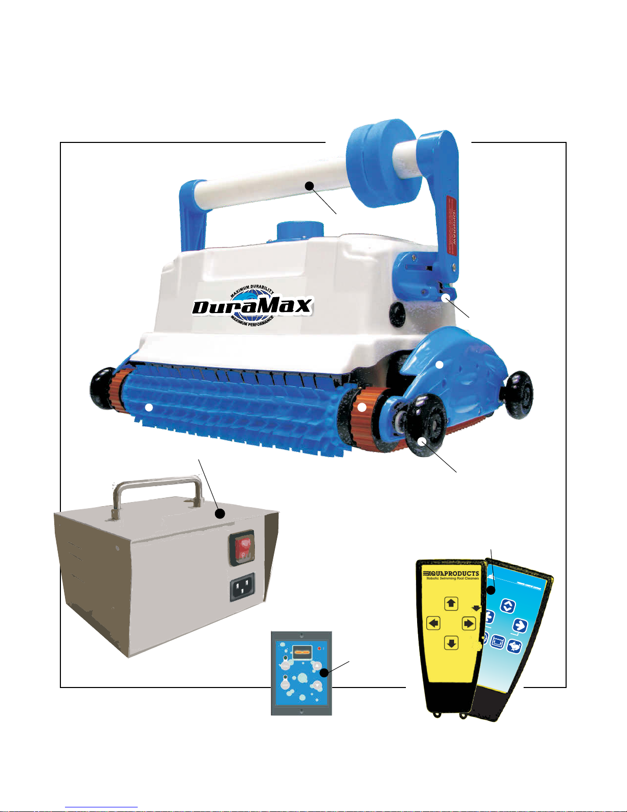
COMPONENTS OVERVIEW
Floating Handle
Handle Bracket
Brush
Power Supply
Drive Track
Electronic
Timer
Side Plate
Bumper Wheels
Remote Control
direction
Delay
delay
climb
speed
3

QUICK START GUIDE
To Operate Cleaner
(1)Locate a GFCI 110 V~ac. receptacle, and plug the Power Supply in.
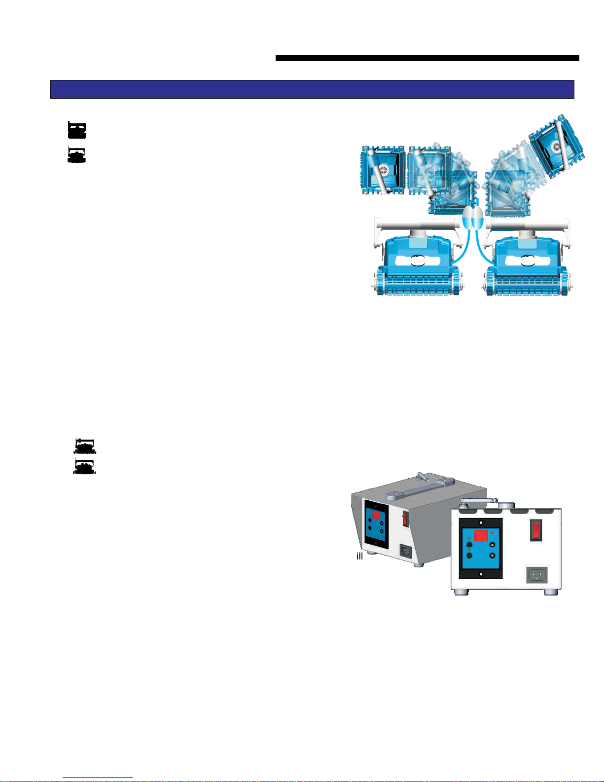
(2) Completely immerse the cleaner in water.
(3) While the cleaner is in the water, gently tilt it side to side (fig3). This will
allow any trapped air to escape through the pump outlets. Then, with a
gentle push, allow the cleaner to sink to the bottom of the pool.
NOTE: If the cleaner does not sink to the bottom of the pool, it’s a
result of trapped air. This air must be removed for proper operation.
(4) Uncoil the floating cable fully and spread it over the surface of the water as
evenly as possible. Make sure the cable has no tangles or kinks.
(5) To start the Commercial Pool Cleaner, press the Power Supply ON/OFF
switch to the On position. If your Power Supply is equipped with an adjustable Timer you can now select the length
of the cleaning cycle and press the Reset button to start the cleaner.
To Maintain and Protect your Cleaner
Shut off and unplug power supply every time you remove the cleaner from the water.
Clean your filter bag after every cleaning cycle.
Replace worn brushes to ensure maximum cleaning performance.
Save your cleaner’s packaging materials for off-season storage or if shipping to your dealer if
service is required.
Clean the unit with fresh water after every cleaning cycle. This will wash the cleaner free of
chlorine or other chemicals found in the pool, extending the life of all the cleaner’s components.
Do not leave your cleaner or power supply in direct sunlight when not in use.
Periodically straighten out the cable using the E-Z Swivel
CABLE USE AND CARE
The cable may become twisted after a period of time in use. To correct this condition, simply lock the moveable handle
on the top of the cleaner in the opposite diagonal direction. The Commercial Pool Cleaner will now travel in the
opposite direction while cleaning your pool and the cable will uncoil.
Using the Floating Cable to lift the cleaner out of the water will cause severe damage!
4
OPERATING INSTRUCTIONS
Check the cable periodically for external damage. Continual rubbing against sharp or rough surfaces may
abrade the Floating Cable resulting in damage and possible short-circuiting of the cleaner.
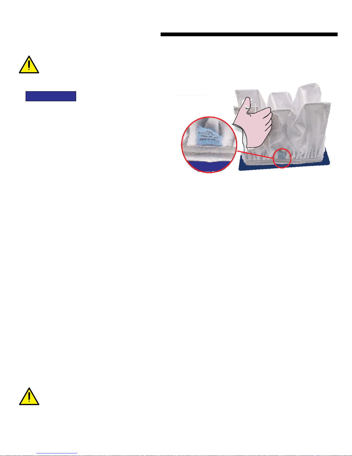
Filter Bag
Lay the cleaner on its back on a soft surface to avoid
scratching it. Gently pull-on the Lock Tab on one end
or side of the Bottom Lid freeing one end of the
Bottom Lid. Repeat this procedure on the other end
and remove the Bottom Lid Assembly . Remove the
Filter Bag from the “W” Frames, turn it inside out and
wash off all the dirt with a garden hose or in a bucket. Squeeze
the Bag gently until the rinse water is clear. If necessary, machine wash (Gentle Cycle only) the Bag using only cold
water with NO DETERGENT. You may re-install the bag immediately or allow it to air dry (never machine dry the Filter
Bag). Re-install the Bag on the “W” frames of the Bottom Lid Assembly, making sure that the “felt” (soft) side is facing in.
To ensure a proper fit of the Filter Bag onto the Bottom Lid Assembly, locate the small Label near the Filter Bag's elastic
bottom (Ref 2.1). Position the Filter Bag so that the small Label is at the center of either long side of the Bottom Lid.
Then pull the elastic bottom over each Wire and slide the Filter Bag down along the Wires until the Bag reaches the
Bottom Lid. At that point, the Filter Bag's elastic bottom should be stretched over the plastic ridges located at opposing
ends of the short sides of the Bottom Lid. This holds the Filter Bag in place. Press down on top of the Filter Bag where
each of the four “U” shaped slots on the Wire Frame are located. This will pull the Filter Bag corners to the corners of
the Wire Frame. Re-install the Bottom Lid Assembly into the bottom of the cleaner. Be sure that the Filter Bag's fabric
is not interfering with the locking of the Lock Tabs.
The cleaner's Filter Bag can filter out particles down to 20 times smaller than many main filters. This means that the fine
particles such as algae and bacteria, invisible to the naked eye, which slip through the main filter and back into the pool
to settle into the pores of the pool's surface, will be scrubbed loose and vacuumed up by the cleaner and retained in its
Filter Bag. When the Filter Bag becomes saturated with debris, the flow of water through it becomes restricted and
suction is reduced. Strong water flow is required to force the cleaner against the wall when climbing. A dirty Filter Bag
also weighs the cleaner down, making it hard for the cleaner to climb due to the added weight and reduced water flow.
Temperature and chemical composition changes can greatly affect the buoyancy of your cleaner.
Therefore, if you have previously installed floatation devices in your cleaner to assist its buoyancy, it may
be necessary to remove the devices one by-one until proper buoyancy is restored.
5
BOTTOM LID ASSEMBLY
OPERATING INSTRUCTIONS
DuraMAX
Jr. HT
DuraMAX
Jr. T RC
DuraMAX
Duo
DuraMAX
Trio
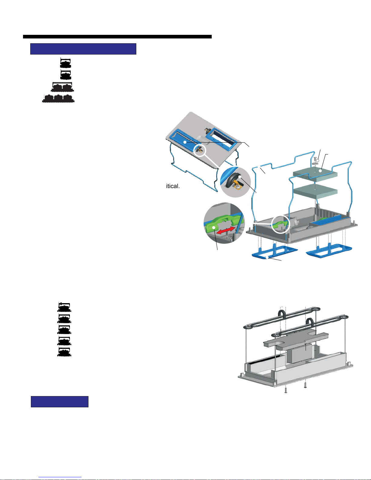
inlet extensions, 1/8” and 1/4”. When using the inlet
extensions observe the cleaners operation in the
pool to see if any obstacles interfere with the
extensions. (3) Your cleaner offers the best
possible performance when it is virtually
weightless in your pool. So, careful balancing
of its weight is important. Generally, a new
cleaner is very light when used for the first time.
Careful removal of air trapped in the housing is critical.
Additional floatation is typically not required on start-up.
Most pool conditions allow your cleaner to effortlessly
climb the pool walls and stairs up to the waterline. In some
instances the pool environment (e.g., temperature,
chemicals, water, etc.) may offset your cleaner's natural
buoyancy. Therefore, four floats have been included in the
packaging with your new cleaner to assist with its
buoyancy. (4) Located on the inside of the bottom lid and
near the suction inlet is the Suction Selector Switch. If the selector switch is moved towards the “LESS” markings the
inlet flaps will be kept from fully opening .This will increase the suction power of the cleaner, but will also restrict larger
debris from entering the filter.
The Bottom Lid Assembly has several options that will permit you to control the way the cleaner
operates. The bottom lid consists of six parts. (1) Two rollers are located adjacent to the inlets. This
prevents the cleaner from being stuck on obstacles like drain covers. If they are not needed, the rollers
may be removed by removing a single phillips screw. (2) The inlet extensions will lower the suction point
of the cleaner. The lower the suction point, the greater the suction. Your cleaner comes with two sets of
Inlet Flaps
Wire Frame
Roller
Suction selector
Inlet Extension
Float Screw
Float
DuraMAX
DuraMAX
o
BiTurb
BiTurbo T2
R C
T
DuraMAX
DuraMAX
DuraMAX
RC
Duo Jr.
floatation, add the two remaining Pocket Floats. Pocket Floats do not
require any screws or glue. Simply place them into the open rectangular
cavities outside to the side of the Intake Flap housing.
To Add Floatation: (1) Remove the two Screws from the “H”-
Float. Then, place the “H”-Float, foam-side down, against the
inside base of the Bottom Lid Assembly. Secure the “H”-
Float with the two screws provided by fastening them from
the outside of the Bottom Lid Assembly. This should provide
adequate buoyancy. (2) Should your cleaner require more
AIR SENSOR
The DuraMAX line of cleaners has a sensor that permits the use of these cleaners in zero-depth entry pools. ™ If the
Robot leaves the water for any reason, the system will detect the fault and will attempt to return the robot to safe
operating water level (Back to the pool).
6
OPERATING INSTRUCTIONS
DURAMAX Jr. HT, DURAMAX Jr. T RC, DURAMAX, DURAMAX BiTURBO T RC
DuraMAX
Jr.HT
DuraMAX
Jr. T RC
continue its cleaning cycle.
FEATURES
If the machine for any reason gets stuck on the pool floor for more than
2 minutes or if the machine does not see a wall within 2 minutes it
The DuraMAX
down the Pump Motor for a 6 second period
operation. During this period the Cleaner will turn and then
Jr. HT program operates by
shutting
during its
DuraMAX
DuraMAX
o
BiTurb
reverses itself..
OPERATION
After the Power Supply main switch is turned on (fig. a) and the C-
run/Reset Switch is pressed on the power supply,(fig.b) the machine
will run a test sequence for the first 9 seconds. Then the machine will search for a wall. When it finds a wall the machine will
climb the wall for 15 seconds, will reverse, go down the wall and move away from the wall for 21 seconds, it will reverse and go
back towards the wall for 5 seconds. The pump will turn off and perform a turn. After this the pump will turn back on and will
return again towards the wall. The machine will climb the wall for 2 seconds, reverse for 25 seconds and will reverse again.
The machine will repeat this three times. On the fourth time the Cleaner will cross the pool to the opposite wall and repeat the
first three actions moving in the opposite direction
The DuraMAX c
cleaning pattern of the an be adjusted by the user by adjusting the foam float located on
R C
T
Alternatively, the closer the float is towards the center a smaller
angle can be achieved. To make the cleaner turn right the float
should be located on the left side. To make the cleaner turn left
locate the float on the right side. Rotating the float from side to side will
the floating handle. The further from center the float
is located the further the cleaner will turn.
b.
DuraMax DuraMax
a.
keep the Cable from tangling
DURAMAX FEATURES
If for any reason the machine gets stuck on the pool floor for more than 2 minutes or if the machine does not see a wall within
2 minutes, it reverses itself. If for any reason the machine gets out of the water, it will reverse itself every 25 seconds.
If the machine is on the pool wall and does get down to the pool floor, the machine will reverse itself after 30 seconds and
then will reverse again after 30 seconds. If the machine remains on the wall or is up-side down for over 2 ½ minutes, the
pump will turn off for 30 seconds and let the machine settle to the bottom of the pool. If during the next 30 seconds, the
machine remains on the wall or up-side down the machine will shut down to protect the cleaner from harm.
7
OPERATING INSTRUCTIONS
DURAMAX BI-TURBO T2
DURAMAX OPERATION
After the Power Supply main switch is turned on (fig. a) and the C-run/Reset
Switch is pressed on the power supply,(fig.b) the machine will run a test
sequence for the first 9 seconds. The default program for the DuraMax is floor
only. The program can be changed using the R/C transmitter. (pressing the
Turn Button, then turn the power supply ON and push the C-Run button on the
Power Supply to put the Cleaner in the wall and Floor mode) When the unit is
turned OFF the Power Supply will reset the Unit back to floor only mode.
When the unit is in the floor and wall mode, the unit climbs the wall every 4th
time for 15 seconds. Then the machine will search for a wall, it will reverse and
go back towards the wall for 5 seconds, the pump will turn off and perform a turn. After this the pump will turn back on and
will return again towards the wall. The machine will climb the wall for 2 seconds and reverse for 35 seconds and will
reverse again. The machine will repeat this three times. On the fourth time the Cleaner will cross the pool to the opposite
wall and repeat the first three actions moving in the opposite direction
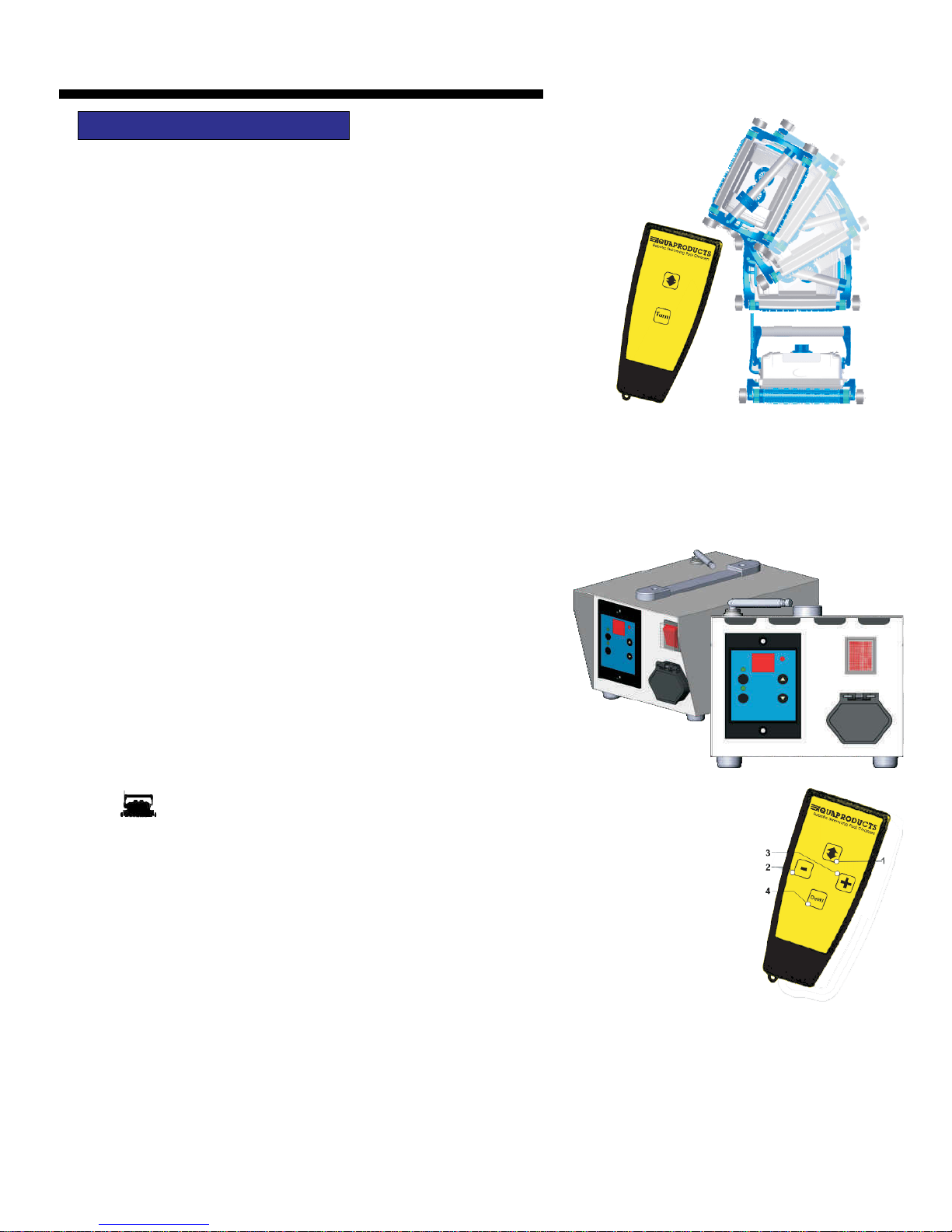
REMOTE CONTROL
When using the Remote Control, fully extend the antenna on the
transformer and aim the Transmitter towards the Power Supply.
Make sure the antenna on the transformer is fully raised for best
performance. Pressing the up and down arrow button will cause the
cleaner to reverse direction and the “Turn” Button will guide your
cleaner either Left or Right depending in what direction unit is
traveling for as long as the button is being pressed.
DuraMAX
BiTurbo T2
The UP/DOWN button allows the machine to reverse itself both on the wall and floor. If for any
reason the machine is stuck on the pool floor for more than 6 minutes or if the machine does not
climb a wall within 6 minutes, it will reverse. If the machine climbs out of the water, it reverses itself
every 25 seconds, until water is found. If water is not located within three minutes the cleaner will
shut itself off.
The machine may be programed for wall and floor or floor only cleaning. The default mode is set to
floor only . To change the mode to cleaning floor and wall, press the forward/reverse button on the
remote control once then turn the Main Power Supply switch on and the floor only mode will be
engaged. Turn the Main Power Supply switch on. The machine will first search for the wall. After it
finds the wall, the machine will climb the wall and remain on the wall for two seconds, then it will reverse and head back
down the wall. After the machine reaches the floor, it will move away from the wall for 30 seconds. The 30 second time
should be adjusted from 20-40 seconds so the cleaner has enough time to go slightly past the middle of the pool. The time
may be adjusted by pressing the + or - buttons on the remote control transmitter The + button will increase the time to a
maximum of 40 seconds and “-” decreases to a minimum of 20 seconds. After the time is correctly set. The cleaner will go
from the wall to the center of the pool then reverse, go back towards the wall and climbs the wall for 2 seconds. Each time
DURAMAX BI-TURBO T2 has a delayed start feature where the machine can
start cleaning the pool an hour after the Main Power Supply is turned on. This is done
by switching the power supply on and pressing the delay button on the remote control.
8
OPERATING INSTRUCTIONS
the machine reverses an internal clutch in the wheel tube will cause the cleaner to turn slightly. This sequence will repeat
three times. On the fourth time the machine will climb the wall for ten seconds This sequence will repeat 30 times then the
machine will cross the pool and travel in the opposite direction.
DURAMAX DUO/DUO Jr/RC This machine has a delayed start
DuraMAX
RC
DuraMAX
Duo Jr.
DuraMAX
Duo
stuck on the pool floor for more than 6 minutes it will reverse (the Duramax RC has
2.5 minutes before reversing.) If the machine does not climb a wall within 6
minutes, it will reverse in the other direction. If the machine climbs out of the water,
it reverses itself every 25 seconds. The machine can be programed for wall and
floor or floor only cleaning. The default mode is set to clean the floor only. To change the
mode to clean the floor and wall, press the forward/reverse button on the remote control
once then turn the Main Power Supply switch on and the floor only mode will be engaged.
After the Power Supply switch is turned on the machine will first search for the wall. After it
finds the wall, the machine climbs the wall and remains on the wall for 2 seconds or 45
seconds ("pool floor only" and "pool floor and wall" mode respectively) after which it reverses itself
to head towards the pool floor. The machine will move away from the wall for about 2 seconds
turn, reverse and will search for the opposite wall. The machine will climb the wall and remains on
the wall for 2 seconds or 45 seconds ("pool floor only" and "pool floor and wall" mode
respectively) after which it reverses itself towards the pool floor. After this the program will
repeat itself. Between 1 to 4 minutes the machine will turn on the pool floor. The machine will
perform a 90 degree turn and alternate between right and left turns
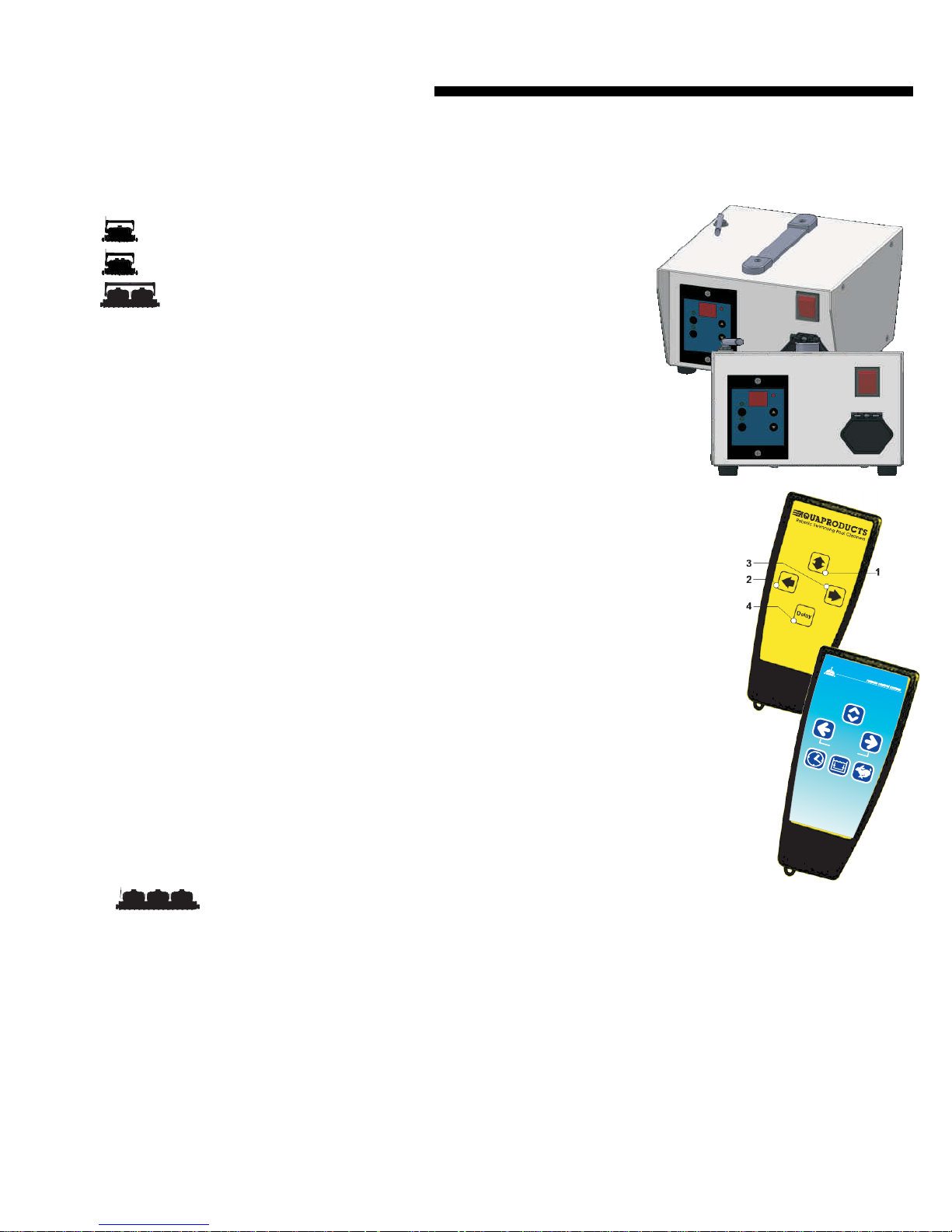
feature where the machine can start cleaning the pool an hour after
the Main Power Supply is turned on. This is done by switching the
power supply on (fig 1) and pressing the delay button on the remote
control (No.4). The UP/DOWN button allows the machine to reverse
itself both on the wall and floor. If for any reason the machine is
Fig. 1
SIX BUTTON REMOTE
Up/Down – Press once to change the current direction (Forwards/Backwards) of your cleaner.
Left – Press and hold to turn the cleaner to the Left. Release the button when the unit is moving in
the desired direction.
Right – Press and hold to turn to the Right. Release the button when the unit is moving in the
desired direction.
Delay – Press once to delay the cleaning cycle of your cleaner by 1 hour. This feature allows the
cleaner to start working after the debris has settled to the bottom of the pool. Pressing the button again
will cancel the 1 hour delay and your cleaner will start working immediately.
Climb – Press once to switch between the floor only and floor-and-wall mode.
Speed – Press once to switch between Standard cleaning speed and Detailed cleaning speed (slower).
DuraMAX
Trio
This machine has a one hour delayed start feature. The cleaner can start cleaning the pool an hour after
the Main Power Supply is turned on. This is done by switching the power supply on (fig 1) and pressing
the delay button on the remote control (Fig 4). The DURAMAX TRIO is a floor cleaning machine only. The UP/DOWN button
allows the machine to reverse itself on the pool floor. If the machine is hung-up on the pool floor for more than 5 minutes or if
the machine does not reverse within 8 minutes, it will reverse in the other direction. If the machine leaves the water, it will
reverse itself every 25 seconds until it locates water. If water is not located it will shut itself off. After the Power Supply switch
is turned on the machine will first search for the wall. After it finds the wall, the machine climbs the wall and remains on the
wall for 2 seconds turn, reverse and head towards the pool floor. The machine will move away from the wall for about 2
seconds, turn, and will search for the opposite wall. It will climb the wall and remains on the wall for 2 seconds after which it
will reverse itself towards the pool floor. After this, the program will repeat itself. Between 1 to 4 minutes the machine will
turn on the pool floor. The machine will perform a 90 degree turn alternately between the right and the left.
direction
delay climb
speed
9
DuraMAX
DuraMAX
BiTurbo T2
DuraMAX
RC
DuraMAX
Duo Jr.
DuraMAX
Duo
DuraMAX
Trio
(2) Turn the cleaner upside
down and remove the Bottom
OPERATING INSTRUCTIONS
DRIVE TRACK AND BELT
With prolonged usage of the cleaner the Drive Tracks may stretch, or wear. To
maintain optimum performance they will require replacement. To
access the gear assembly it is necessary to
remove the cleaner’s Side Plate.
(1) Remove the Bumper wheel
by removing the “C” clip
and then the locking
screw (FIG 3).
Lid Assembly. Locate and remove the four screws
that hold the Side Plate to the main body. The Side
plate is now free and ready to be removed.
(3) When the Side Plate is taken apart, you will notice 3
black bushings. It is a good idea to also replace these
Bushings when the Drive Tracks are replaced.
(4) After the Drive Tracks and Bushings are replaced,
reassemble the Side Plate as shown here. (FIG 4)
SUPER E-Z BRUSHES
To Change Super Brushes for full length and “split” Wheel Tubes:
Using a pair of pliers, grab one end of the stainless steel Rod that is securing
the old Brushes onto the Wheel Tube. Pull away from the Wheel Tube slowly
until the entire existing Brush is freed and removed. Wrap the new Super
Brush around the Wheel Tube. Join the ends of the replacement Super Brush
using the Metal Rod supplied in the package. Slide the Rod through the Tabs
molded into the ends of the Brush. Make sure that
the Rod is inserted through every Tab.
(FIG 5)
fig.3
fig.5
fig.1
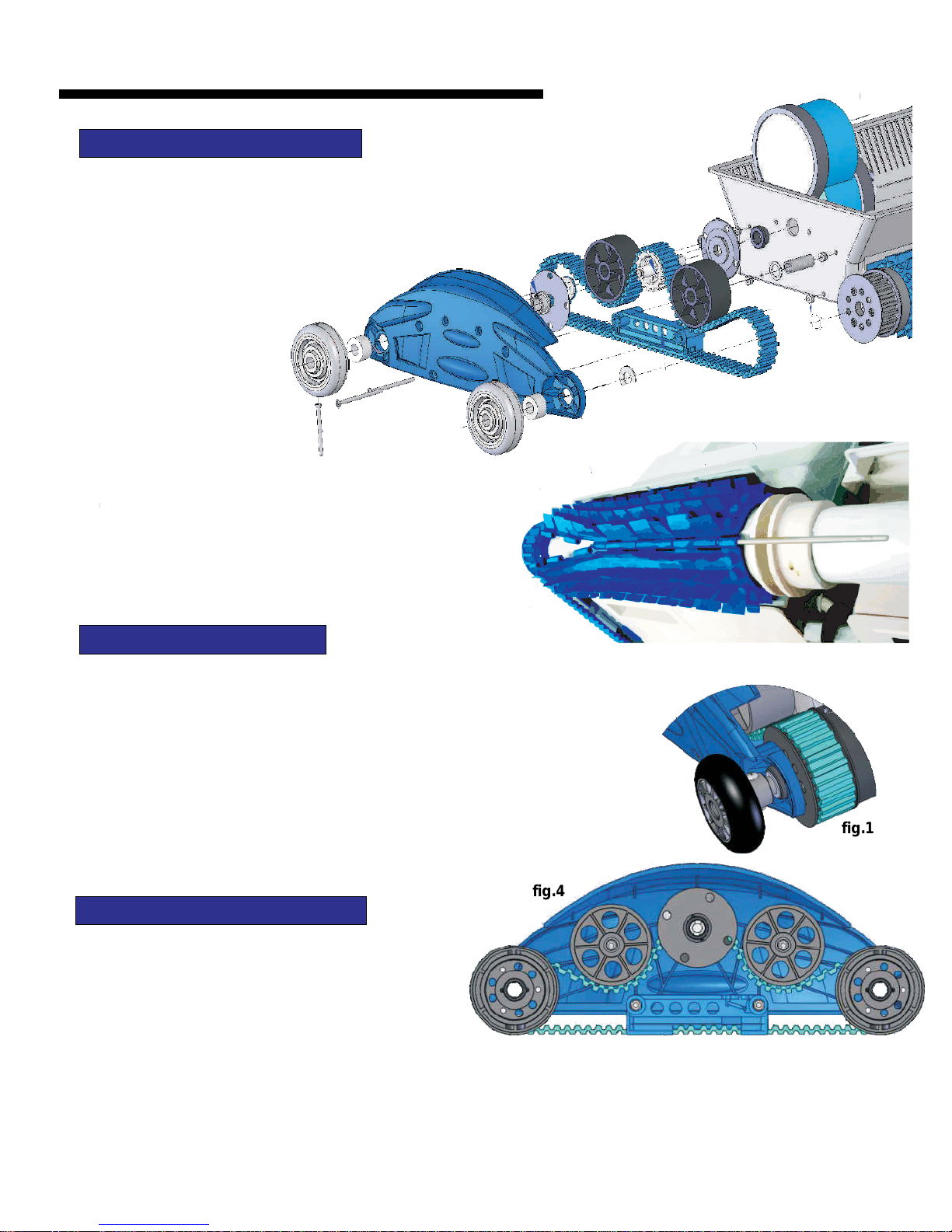
CHANGING DRIVE BELTS
\
DuraMAX
DuraMAX
BiTurbo T2
DuraMAX
DuraMAX
Duo Jr.
DuraMAX
DuraMAX
To remove the drive belts, locate the small hole
on the outboard wheels (fig.#1) and remove
with a slot screwdriver. Repeat for all four
wheels.
RC
Then remove the bolts and nuts from the Side
Plate (fig.#3) at four places. After you remove the Side Plate the interior assembly of the Drive Pulley, Idlers, and
Duo
Wheel Tubes will fall onto the work surface. Take note as to where the internal parts are located. Refer to the
Trio
picture above to see the way the Drive Belt is threaded through the Pulleys.
fig.4
10
 Loading...