

DuraMax 10 Ft WoodBridge Owner's Manual
• All Weather Durable PVC
• Won’t Dent, Rust, Rot or Mildew
• Tall Walk In Shed
• Never Needs Painting
• 61 Inch Wide Double Doors
• Easy Assembly
• High Wind Tested
• Snow Load Tested 20lbs/sq. foot
• Pad Lock Ready (Lock not included)
• Wooden or Cement Foundation Needed
Call us for any missing or damaged parts.
Do not return to the store.
Your Total Solution To Maintenance Free Storage Sheds.
Available Kits
• Foundation Kit Available
• Modular 2.5 Ft Extension Kits Available
• 10 Ft x 8 Ft Window Kits Available
Ver: 4.0
Building Dimensions :
Approximate
Size
Storage
Exterior Dimension Interior Dimension
10 Ft x 8 Ft
79 Sq. Ft
480 Cu.Ft
Roof Edge to Edge
Base Dimension
Door Opening
3.2 m x 2.4 m
7.3 Sq.m
13.6 Cu.m
Width
Depth
Height
inch cm
125 3/8 318.4
inch cm
94 1/4
239.3
125 1/2
318.7
95 1/8
241.6
85 1/2
217.1
inch cm
123 3/8 313.3
inch cm
92 1/4
234.3
60 5/8
154
71 1/2
181.6
73
185.5
Wall to Wall
Area Volume
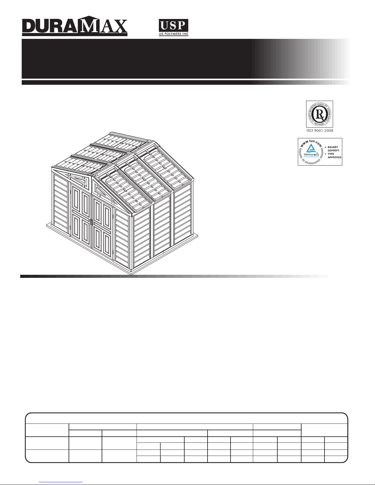
OWNER’S MANUAL /
Instructions for Assembly ‘10 Ft WoodBridge’
Size 10 Ft x 8 Ft / 3.2 m x 2.4 m
(Approx.)
Vinyl Garden Shed
Vinyl Garden Shed
A Product of
TM
ALL PURPOSE VINYL GARDEN SHEDS
Customer
Service Hotline
(800) 483-4674
www.duramaxbp.com
Patent #416.091

Duramax Garden Shed
Limited Fifteen Year Warranty
U.S. Polymer Inc. will send a replacement part free of charge, in the event of material defects and or
workmanship for a period of fifteen years from the date of purchase.
This warranty is extended only to the original purchaser. A purchase receipt or other proof of date of
original purchase will be required before warranty service is rendered. In no event shall we pay the cost
of flooring, labor, installation or any other costs related thereto.
This warranty only covers failures due to defects in material or workmanship which occurs during normal
use and does not extend to color change arising due to normal weathering or to damage resulting from
misuse or neglect, commercial use, failure to follow assembly instructions and the owner’s manual
(including proper anchoring of the shed), painting, forces of nature and other causes which is beyond
our control.
Claims under this warranty must be made within the warranty period by calling 1-800-483-4674 or mail
in a dated sales slip and clear photograph of the part to:
U.S. Polymers, Inc.
1057 S. Vail Ave,
Montebello, CA 90640.
We reserve the right to discontinue or change components. If a component has been discontinued or
is not available,
U.S. Polymers, Inc. reserves the right to substitute a component of equal quality as may be compatible.
Limits and Exclusions
There are no express warranties except as listed above. The warrantor shall not be liable for incidental
or consequential damages resulting from the use of this product, or arising out of any breach of this
warranty. All express warranties are limited to the warranty period set forth above . Some states do not
allow the exclusion or limitation on how long an implied warranty lasts, so the above limitations may not
apply to you.
This warranty gives you specific legal rights and you may also have other rights which vary from state
to state or country to country.
Behind left Door Panel for Basic Shed.
Location of Product Labels
On Side Panel for Extensions.
1
2
SAFETY & PRECAUTIONS
Before You Begin...
1. Check your local building codes regarding footings, location, etc.
2. Select a site that allows enough working space around the shed.
3. Determine building foundation and anchor system.
4. Read and understand the Owner’s manual enclosed in the package.
5. Follow all directions and dimensions thoroughly.
6. Follow the steps given in the manual carefully for correct assembly.
7. Make sure all parts are present before you start assembling.
8. BE SAFE : Follow safety instructions and avoid injury.
(See inside page).
9. GROUND MUST BE EVEN : Make sure the foundation frame lies flat on
the ground. If the earth bed is uneven, remove sod and other debris and
level it with a flat shoval.
10. Separate contents of the carton by the part number and review the list.
Be sure you have all the necessary parts for your shed.
Refer Owner’s manual for part list.
CAUTION
Sharp
Edges
3
SAFETY & PRECAUTIONS
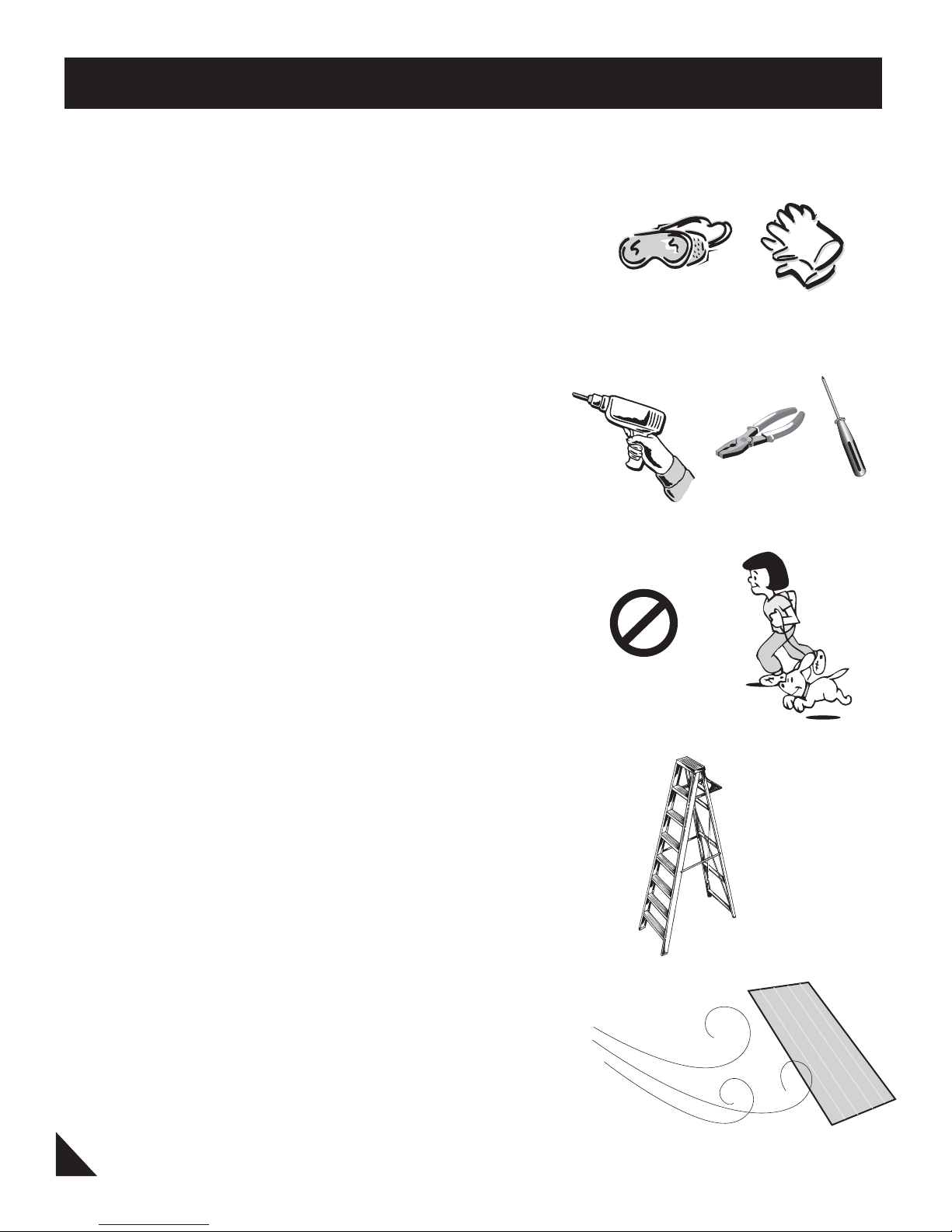
For your own safety, please read and follow these instructions during the shed assembly.
1. Always wear work gloves, long sleeves and eye
protection during assembly of the shed. Some pieces
of the shed contain sharp edges and can cause injury.
2. Be cautious with the tools used for the assembly of
the shed. Familiarize yourself with the operation of all
the power tools.
3. Children and pets should be kept away from the
assembly site to avoid any distractions and accidents.
4. When using a step ladder, make sure it is on even
ground and fully open with the safety latch in place.
Never concentrate your full weight on the roof or any
part of the shed.
5. Do not attempt to assemble the shed on a windy day.
Shed panels can be whipped across by the wind
making the worksite difficult and dangerous.
4
IMPORTANT
Wear eye protection when using any form of power tools. Do not use voltage power tools in a wet or damp
enviornment to avoid electric shock.
Do not use any part of the shed as a means of personal support while attaching components during assembly.
The shed must be constructed on a solid base foundation. A concrete pad or a large size concrete patio
stone squares is recommended for suitable floor base. Make sure it is firm and level and will allow drainage
away from the site. The base foundation should be at least 4 inches (100mm) larger than the shed dimensions.
Please refer to the front page of your owner’s manual for the exterior dimensions of the shed. Manufacturer is
not responsible for the choice and construction of the foundation.
For a concrete pad base, prepare a level bed for a firm footing layer of crushed stone. The concrete pad
should then be poured to a thickness of 4 inches (100mm) to 5 inches (125mm). Allow to dry thoroughly
for at least 48 hours
Your shed must be firmly anchored to the concrete pad or large concrete patio stone squares, to help protect
against damage in high winds.
Care & Maintenance
Although this unit does not require any maintenance, care should be taken to prolong the life
of your shed.
ROOF : Keep roof clean of leaves and snow with long handled, soft bristled broom. Heavy amounts
of snow on the roof can damage the shed making it unsafe. Do not step on the roof.
WALLS : Do not rest any object against the wall panels of the shed.
DOORS : Keep doors closed to prevent wind damage.
FASTENERS : Regularly check your shed for loose screws, bolts, nuts, etc. And retighten them as
necessary.
MOISTURE : With changing temperatures, condensation will accumulate inside the shed. Good
ventilation will help in regulating and avoid moisture.
TIP : A noncorrosive caulking is helpful to seal the shed.
DO NOT store swimming pool chemicals in your building.
Combustibles and corrosive must be stored in
air tight containers
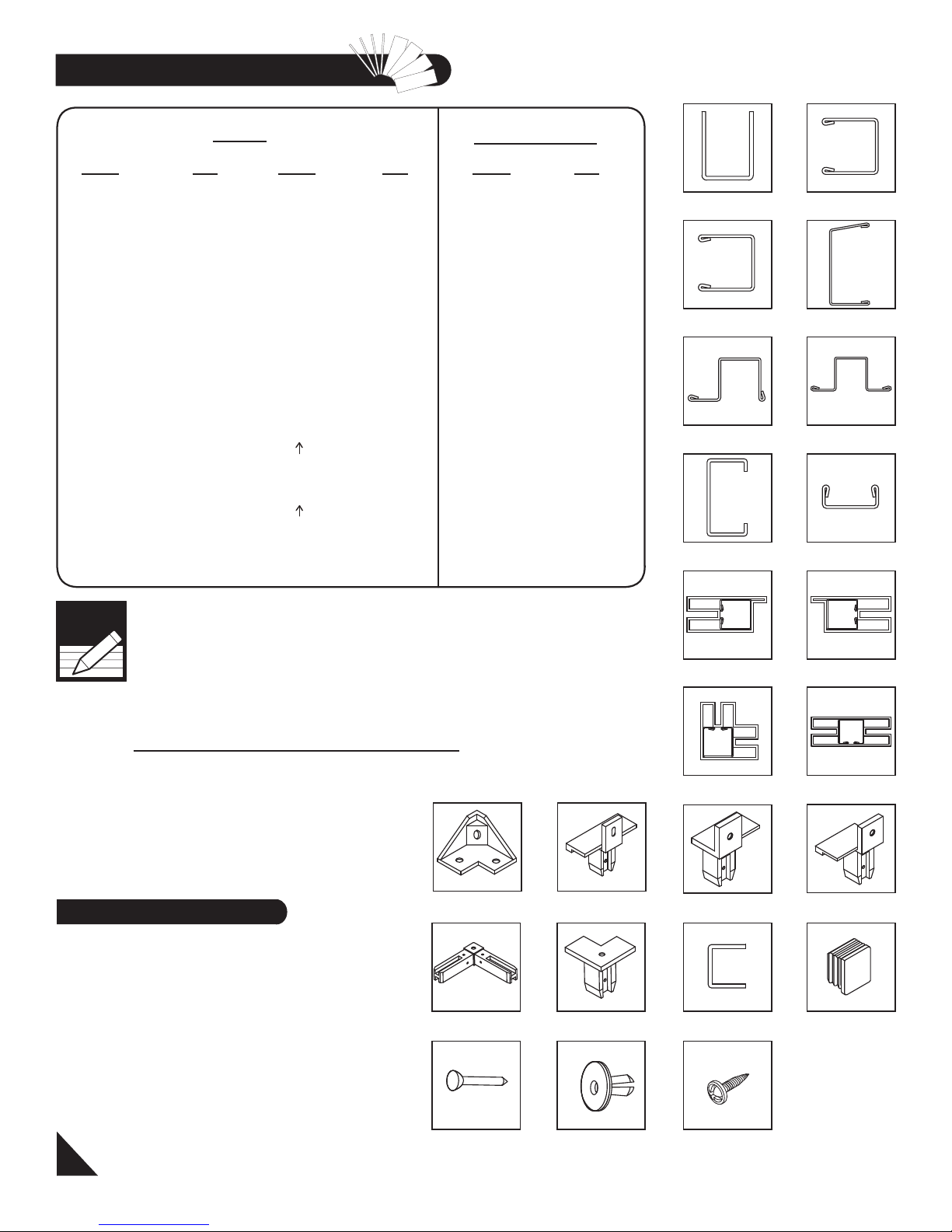
Parts List
Cordless Drill - Philips Head
Hammer or Rubber mallet
Carpenters Square
8’ Step Ladder
Adjustable pliers
Level -
3ft.
Tape Measure
Caulk Gun
Waterproof Clear Silicon
Sealant
Hand Gloves
Tools You Will Need
2. Maximum no. of Extension can be build
upto 10’x13’ (ie. Two Extension).
Note
3. Shed with more than two extensions
require Roof Super Support.
Recomended Qty of Roof Super Support
For 10’x8’ Vinyl Shed - 2Nos.
For additional each Extension - 1No.
1. Before starting installation, please refer
Safety & Precautions.
5
B1LA, B1RA, B21,
B22, B3LA, B3RA
CB1A, CB2A,
CB3XA, CB4A, MJ
RS1A, RS3XA,
RS3LA, RS8A, RS9A
RS5A, RS6XA,
RS7XA
RS2A, RS10A, RS4XA, RS11A,
RS12A
DSH RS14A
CDLA CDRA
CCA CMA
FDCL
FDCR
FCB FMC
FCCRJ
EPS
CBC
PIN PPG & PWS S1, S2, S7
CODE
QTY
B1LA 1
B1RA 1
B21 2
B22 2
B3LA 1
B3RA 1
CB1A 2
CB2A 2
CB3XA 4
CB4A 2
RS1A 4
RS2A 4
RS3LA 2
RS3XA 2
RS4XA 4
RS5A 4
RS6XA 2
RS7XA 2
CODE
QTY
FDCL 1
FDCR 1
FCC 4
FMC 7
FCB 4
RJ 4
EPS 4
CBC 3
PPG 80
PIN 80
S1 253
S2 8
S7 16
CODE
QTY
RS8A 4
RS9A 4
MJ 7
RS10A 2
RS11A 2
RS12A 2
RS14A 12
DSH 1
CMA 7
CCA 4
CDLA 1
CDRA 1
SP 12
FPL 2
FPR 2
RP 6
RRS 3
DL 1
DR 1
PARTS ACCESSORIES
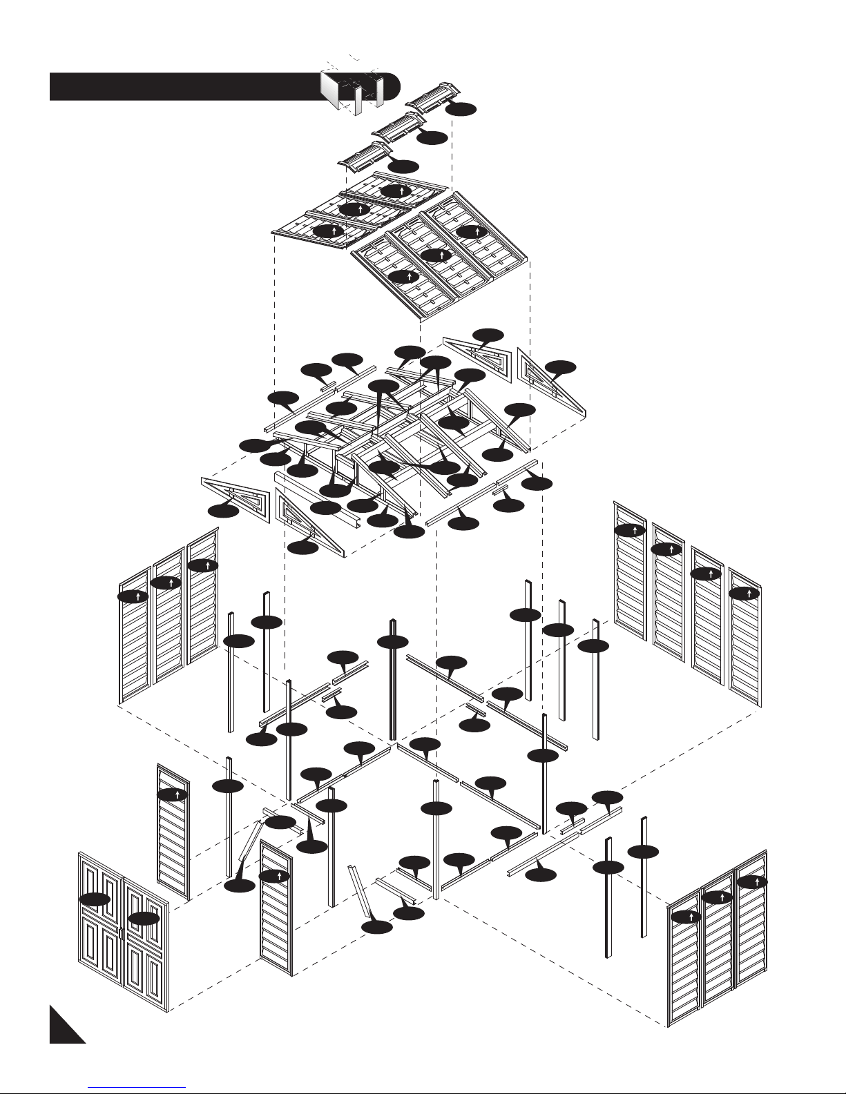
Exploded View
SP
CB4A
CB1A
B1LA
B1RA
B21
B22
B22
B21
B3LA
B3RA
6
RP
RP
RP
RP
RP
FPL
FPR
FPR
FPL
RS3LA
RS3XA
MJ
RS3LA
RS3XA
MJ
RS1A
DSH
RS1A
RRS
RRS
RRS
RP
RS8A
RS9A
RS2A
RS4XA
RS9A
RS2A
RS4XA
RS6XA
RS7XA
RS12A
RS10A
RS11A
RS2A
RS1A
RS2A
RS5A
RS5A
SP
SP
SP
SP
SP
SP
SP
SP
SP
DL
DR
CMA
CMA
CMA
SP
SP
CMA
CMA
CMA
CMA
CCA
CCA
CCA
CCA
CDLA
CDRA
CB3XA
CB2A
MJ
CB3XA
MJ
CB2A
CB3XA
MJ
CB3XA
CB1A
CB4A
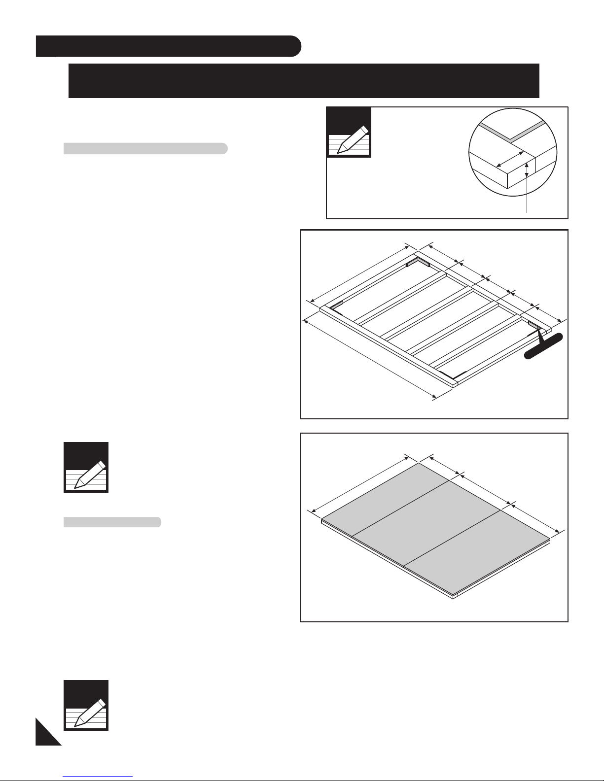
A. Foundation
7
1. Use pressure treated wood studs 2 x 4 (Actual
size 2” x 3 1/2”, 50mm x 88.9mm) to create a
platform frame that has an outside dimension of
94 7/8” x 126” (2410mm x 3200mm).
DuraMax must be installed on a level wooden
platform or a level concrete foundation.
2. Using exterior grade CDX 3/4” (19mm)
plywood, cut and fit together the sheets to form
solid foundation as shown. Foundation must
be square and level.
The following are the list of lumber and sizes
you will need.
Wooden Platform (Not Included)
Pressure Treated - Wood Studs:
2ea 2” x 3 1/2” x 126” (50mm x 88.9mm x 3200 mm)
6ea 2” x 3 1/2” x 87 7/8” (50mm x 88.9mm x 2232.2 mm)
Exterior Grade (CDX) - 3/4” (19mm) plywood
2ea 3/4” x 48” x 94 7/8” (19mm x 1219.2mm x 2410mm)
1ea 3/4” x 30” x 94 7/8” (19mm x 761.6mm x 2410mm)
L-Brackets: 4ea
The shed must be constructed on a solid
base foundation. A concrete pad or a large
size concrete patio stone squares is
recommended for suitable floor base. Make
sure it is firm and level and will allow drainage
away from the site.
The base foundation should be at least 4
inches(100mm)larger than the shed
dimensions. Please refer to the front page of
your owner’s manual for the exterior
dimensions of the shed. Manufacturer is not
responsible for the choice and construction
of the foundation
Concrete Platform
Note
For a concrete pad base, prepare a level bed for a
firm footing layer of crushed stone. The concrete
pad should then be poured to a thickness of 4
inches (100mm) to 5 inches (125mm). Allow to dry
thoroughly for at least 48 hours
If the shed is assembled with
wooden foundation on soil, use the
soil anchor kit.
Note
30”
761.6mm.
48”
1219.2mm.
48”
1219.2mm.
94 7/8”
2410mm.
Note : If you have DURAMAX Foundation, please follow instruction manual
in that package. If not, follow below wooden platform instruction.
Lay 2 x 4
(Actual size 2”x 3 1/2”, 50mm x 88.9mm)
Note
50
mm (2”)
88.9
mm (3 1/2”)
30”
761.6mm.
24”
609.6mm.
24”
609.6mm.
24”
609.6mm.
24”
609.6mm.
94 7/8”
2410mm.
126”
3200mm.
L- BRACKET
8
Parts Needed:
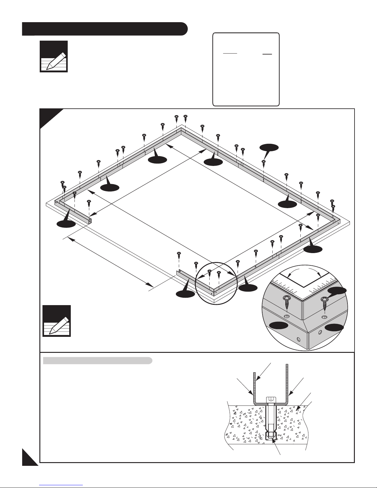
B. Base Frame
Code Qty
B1LA 1
B1RA 1
B3LA 1
B3RA 1
B21 2
B22 2
S1 32
Note
S1
B22
B1RA
90
O
Using a carpenter square, line up corners. Align
base bars, mark the concrete at the holes in the
base and drill concrete with suitable concrete bit to
accept 1/4” x 1 1/2” (M6 x 40mm) anchor bolts.
(Qty - 32Nos. not provided).
Assembly on concrete foundation
Note
Measure in all direction as shown in
figure to make the base channel
assembly in a perfect.
1
1. It is important that these instructions
are followed step by step.
2. All parts are clearly marked and care
should be taken to use the correct one.
3. Don’t install under windy conditions.
4. If you are building the shed against a wall,
build it 2.5 ft. away then slide it in.
M6 Anchor Bolt
Base ‘U’ Channel
Concrete
Outside
Inside
S1
123 3/8”
3133mm.
123 3/8”
3133mm.
92 1
/4”
2343
mm.
92 1
/4”
2343
mm.
61 1/4”
1556mm.
B1RA
B22
B21
B3RA
B3LA
B22
B21
B1LA
9
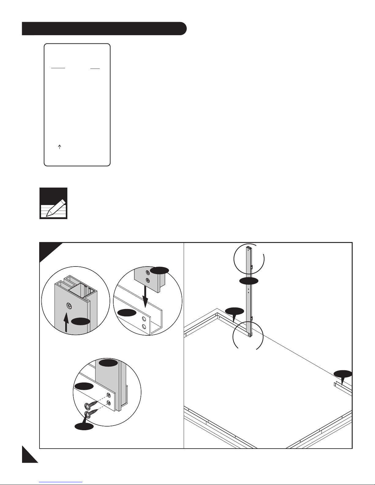
C. Wall & Columns
1
Front
Fig.3
Fig.1
CDRA
Fig.2
CDRA
B1RA
Right
Back
Left
1
2&3
B1RA
CDRA
B1LA
B1RA
CDRA
S1
Parts Needed:
Code Qty
CMA 7
CCA 4
CDLA 1
CDRA 1
CB1A 2
CB2A 2
CB3XA 4
MJ 3
CB4A 2
FCB 4
CBC 3
SP 12
S1 63
S2 4
1. All parts are clearly marked and
care should be taken to use the
correct one.
Note
2. Set the Torque limit of your Screw drill to
#3 or #4 to ensure the screws do not
strip the metal reinforcements.
2
Note
Check the stamped label on top of
all panels inside.
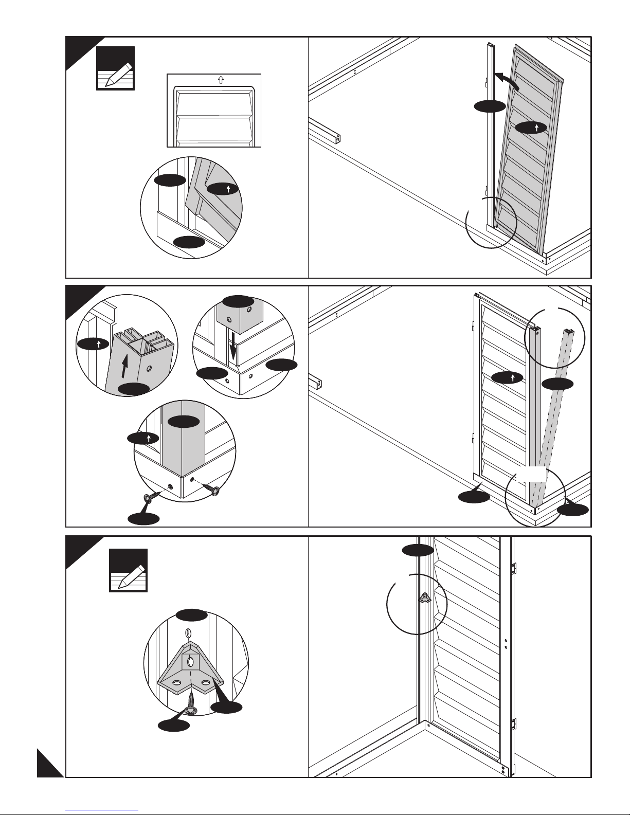
SP
CDRA
SP
3
SP
CCA
Fig.1
SP
CDRA
B1RA
Fig.1
CCA
B1RA
SP
CCA
Fig.2
B22
Front
1
1
SP
CCA
2&3
10
4
Note
S1
Fig.3
Do not tighten the screw.
Leave it loose
CCA
FCB
S2
Fig.1
B1RA
B22
CCA
1
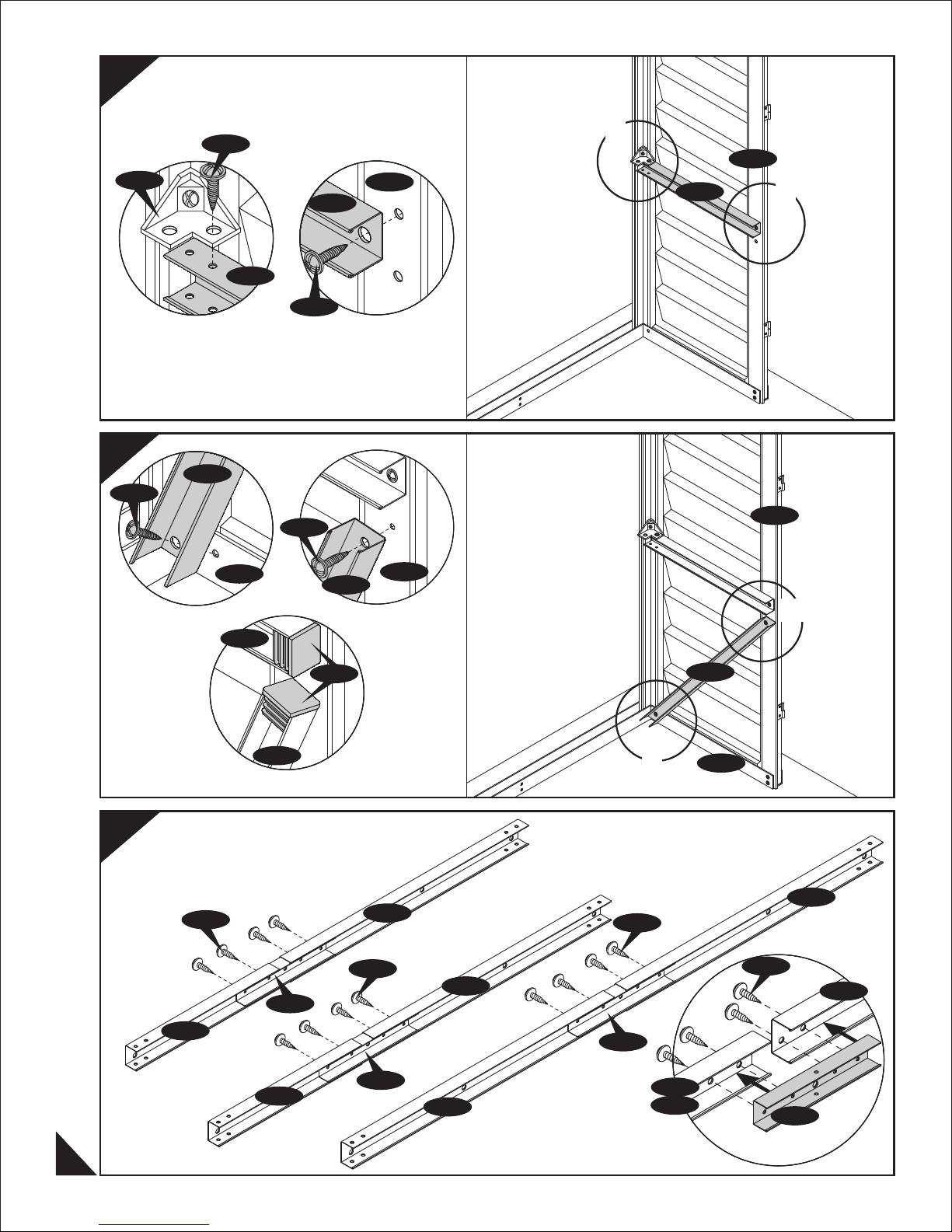
5
6
FCB
S1
Fig.1
CB4A
S1
B1RA
CB1A
S1
S1
CB1A
CB4A
CDRA
Fig.2
CDRA
1
CDRA
CB1A
2
CDRA
7
Fig.1
CB2A
S1
CB1A
CB4A
Fig.3
MJ
EPS
Fig.2
CB3XA
S1
CB3XA
MJ
S1
2&3
CB4A
1
B1RA
CB3XA
S1
CB3XA
CB2A
11
MJ
CB3XA
CB2A
CB3XA
MJ
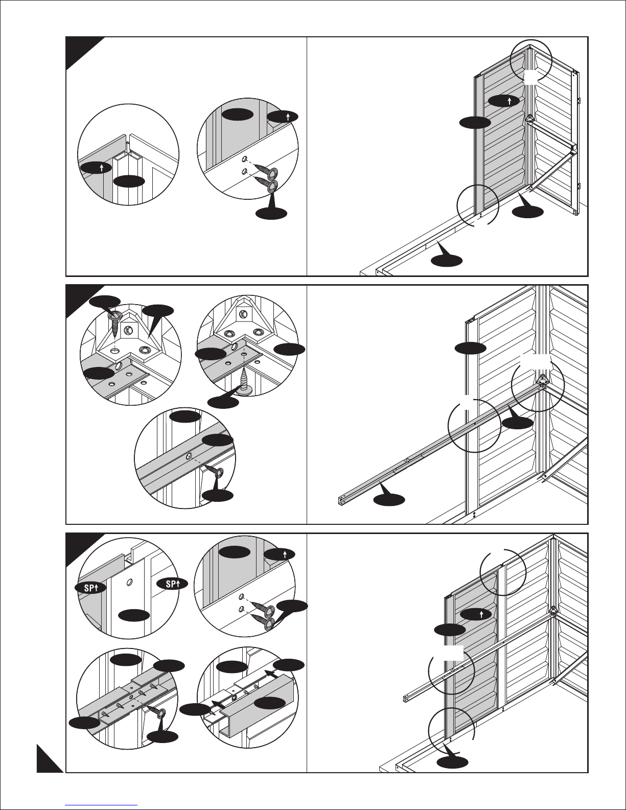
8
9
SP
CCA
Fig.1 Fig.2
S1
FCB
CB3XA
CB3XA
CMA
S1
SP
CB1A
Right Wall
B21
CMA
1
SP
CMA
B22
2
1&2
10
Fig.1
Fig.1
CMA
CMA
Fig.3
CB3XA
CMA
CB3XA
S1
Fig.2
S1
CMA
CMA
Fig.2
SP
CB3XA
3
CB3XA
CB2A
1
S1
SP
CMA
3&4
CB2A
CB2A
S1
12
Fig.3
Fig.4
CBC
2
B21
 Loading...