

Duralloy MIG 200, MULTIMIG 200 PFC MV Owner's Manual
MIG 200
OWNER’S MANUAL
www.duralloy.net.au | 1300 369 456

Congratulations on your new DURALLOY® product!
The DURALLOY range uses latest technology design and engineering to produce welding products
that combine market leading value and features with durability. Designed for discerning operators who
seek professional results and product quality without the price tag of a full professional setup. Design
emphasis is placed on simple, functional design and operation. DURALLOY product is subject to
stringent quality control and designed and manufactured to EN60974-1.2012 standards.
Common use of DURALLOY products include:
• Light Engineering
• Automotive
• Home / Hobby Engineering
• Farming
• Industrial Maintenance & Repairs
For industrial welding solutions, check out the DURALLOY at www.duralloy.net.au
DURALLOY is a market leading provider of innovative power equipment solutions to a wide range of
industries across Australia. Key product categories are; welding equipment, engineering supplies and
abrasives.
www.duralloy.net.au | 1300 369 456
2
MIG 200
OWNER’S MANUAL

www.duralloy.net.au | 1300 369 456
CONTENTS
Know Your Machine
Quick Start Guide
Wiring Diagram
Care & Maintenance
Welding Settings
Basic MIG Welding Guide
Safety
Warranty
3
MIG 200
OWNER’S MANUAL
www.duralloy.net.au | 1300 369 456
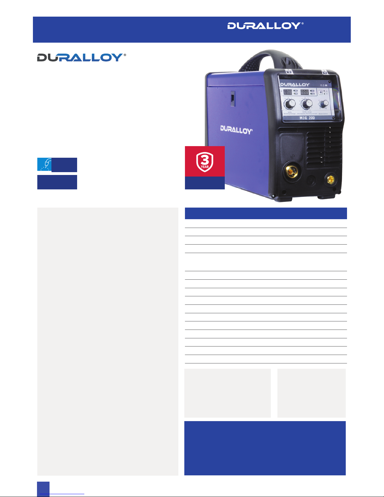
MIG 200
240V MIG Inverter
Welding Machine
PART NO: DA200MIG
4
MIG
Gas & Gasless Operation
ARC STABILITY
Waveform control for added stability of the arc,
even at low current.
DIGITAL DISPLAY
Variable amperage control with digital meters for a
simultaneous welding current and voltage display.
PROTECTION
Equipped with temperature, voltage and current
sensors for greater protection.
FEATURES
• 2 Roll Drive feed System
• Generator Friendly (8.5Kva)
• Industrial Cable Connectors (35-50)
• Industrial Binzel Style MIG Torch MB24
• 240V 15A
• Protective Front Fascia cover
• IP23 Rating
MIG
EN60974-1.2012
APPLICATIONS
• Maintenance
• General Fabrication
• Rural Applications
• On-site Fabrication
MATERIALS
• Mild Steel
• Aluminium
• Stainless Steel
PACKAGE INCLUDES
• Power Source
• 3M MB 24 Style MIG Torch
• 3M Earth Lead
• 1.5M Gas Hose
• Argon Regulator
• Owner’s Manual
• 0.9-1.2 FC Roller for
Gasless Wires
3 YEAR
WARRANTY
MIG 200
OWNER’S MANUAL
SPECIFICATIONS
Power Supply 1-220/230/240 ± 10%
Frequency 50/60Hz
Input Power 5.6 kW
Input Current 40 A
Duty Cycle
40
o
C 10min
200A 30%
145A 60%
110A 100%
No Load Voltage 46 V
Welding Current 40A - 200A
Welding Voltage 12V - 24V
Eciency 85%
Power Factor 0.65
Wire Diameter
Fe, Ss, Flux-Cored: 0.6 / 0.8 / 0.9 / 1.0
Net Weight 12kg
Dimensions 471mm x 213mm x 400mm
Insulation Class H
Protection Class IP23
Cooling Auto Fan
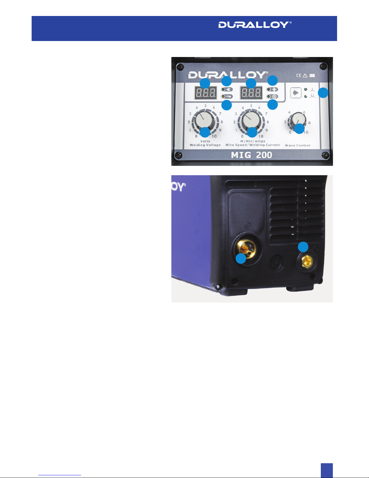
KNOW YOUR MACHINE
More detailed explanations of function on following pages.
1. MIG Wire Feed Speed
2. MIG Voltage
3. Wire Feed Speed/ Current Display Meter*
4. Power Indicator. Lights when input power connected and
machine switched On
5. Error/ Overload Indicator*
6. Display Value Indicator- Wire Feeding Speed
7. Display Value Indicator- Current
8. Trigger Switch Selector 2T/4T
9. Mig Wave Control/ Inductance Knob*
10. Display Value Indicator- Voltage
11. Negative (-) Welding Power Output Connection Socket
12. MIG Torch Euro Connection Socket
www.duralloy.net.au | 1300 369 456
5
MIG Wire Feed Speed
This knob sets the wire feeding speed.
MIG Voltage
This knob sets the welding voltage.
Wire Feed Speed/ Current Display Meter
Displays wire feeding speed in m/minute prior to welding, during
welding displays welding current output.
Display Meter
Displays welding voltage.
Overload/ Error Indicator
Lights when over voltage, over current or electrical overheating
(due to exceeding duty cycle) is detected and protection is
activated. When protection is activated, welding output will be
disabled until the safety system senses the overload has reduced
suciently and indicator lamp goes out. May also trigger if
machine experiences an internal power circuit failure.
When protection is activated, welding output will be disabled until
the safety system senses the overload has reduced suciently
and indicator lamp goes out. May also trigger if machine
experiences an internal power circuit failure.
FURTHER CONTROLS EXPLAINED
12
3
6
10
9
8
11
12
MIG 200
OWNER’S MANUAL
7
4
5

TIPS & TRICKS
Duty Cycle Rating
welding arc that sets the heat. The wire speed feed simply
controls the rate at which the welding wire is fed into the weld
pool. For any voltage position setting, there will be a specific
corresponding ‘sweet spot’ in the wire feeding speed that will
give the smoothest and most stable welding arc. The correct wire
feeding speed for a given voltage setting is aected by welding
wire type and size, shielding gas, welding material and joint type.
It is recommended to set the welding voltage as desired and
then slowly adjust the wire speed until the arc is smooth and
stable. When reaching this point, if the penetration/ heat input
is too much/ not enough, adjust the voltage setting and repeat
the process.If the operator is not able to achieve a smooth and
stable arc with the desired heat input for the weld, it is likely
that a change in wire size and/or shielding gas type is required
(assuming all other factors are correct).
Wave Control
This setting changes the MIG waveform to simulate changing
the inductance of the welding circuit. Inductance controls the
rate of the current rise and fall as the welding wire contacts the
workpiece (known as a short circuit). More inductance increases
the short circuit time and decreases the short circuit frequency
rate. This causes a wider and more penetrating arc, useful for
thicker weld joints. Less inductance will create a narrow more
focused arc. This eect can also be used to fine tune the arc to
produce less splatter. Wire speed, wire size and type, shielding
gas will all change the eect that the inductance setting has
on the welding arc. Inductance change will have no practical
eect on MIG spray transfer process (as opposed to short circuit
process), MMA or TIG welding process.
www.duralloy.net.au | 1300 369 456
6
MIG 200
OWNER’S MANUAL
Electrical Connection
The DURALLOY MIG 200 is designed to operate on a 15A 240V
AC power supply. If an extension cord must be used, it should be
a heavy duty version with a minimum cable core size of 2.5mm
2
.
Operating Environment
Adequate ventilation is required to provide proper cooling.
Ensure that the machine is placed on a stable level surface where
clean cool air can easily flow through the unit. The DURALLOY
MIG 200 has electrical components and control circuit boards
which may be damaged by excessive dust and dirt, so a clean
operating environment is important for reliable product life.
BASIC OPERATION
1. Fitting Wire Spool & Loading Wire Feeder
1.1 Open the wire compartment cover. Unthread the wire spool
retainer. Fit the wire spool to spool holder shaft, ensuring that
the wire exits the spool towards the bottom the spool.
1.2 Set the spool brake tension by adjusting the spool tension
adjustment screw before replacing the wire spool retainer.
The spool brake tension should be set so that the spool can
rotate freely, but does not continue to rotate once the wire
feed stops. This may need to be adjusted as the wire is used
up and the spool weight decreases.
WARNING! Excessive spool brake tension will
cause wire feeding issues and aect welding performance
as well as premature failure/ wear of
wire feed components.
1.3 Feed the wire from the spool through the wire drive inlet
guide into the wire feeder.
1.4 Release the wire feed tension arms by pivoting the wire feed
tension adjustment lever from the vertical to the horizontal
position.
1.5 Check the wire drive roller grooves match the selected MIG
wire type and size. The drive roller will have two dierent
sized grooves; the size of the groove in use is stamped on
the side of the drive roller. For flux cored ‘soft’ wire, such as
that used in gasless MIG welding, the drive roller groove has
a serrated profile (known as knurled). For solid core ‘hard’ MIG
wire, the drive roller groove used has a ‘V’ shaped profile. For
Aluminium solid core ‘soft’ MIG wire, the drive roller required
has a ‘u’ shaped groove. If necessary, remove and change the
drive roller by unthreading the drive roller retainer.
1.6 Once the correct drive rollers are selected and fitted, manually
feed the wire through the wire drive inlet guide through the
www.duralloy.net.au | 1300 369 456
drive roller grooves and into the brass outlet wire guide tube.
Ensuring that the wire is correctly seated in the drive roller
grooves, replace the wire feed tension arms and lock them
into place by rotating the wire feed tension adjustment lever
back to the vertical position.
Adjusting wire feed tension: this is accomplished by winding the
knob on the tension adjustment lever. Clockwise will increase
tension, anti-clockwise will decrease drive tension. Ideal tension
is as little as possible, while maintaining a consistent wire feed
with no drive roller slippage.
Check all other causes of excess wire feeding friction causing
slippage first, such as; incorrect/ worn drive roller, worn/ damaged
torch consumables, blocked/damaged torch wire guide liner,
before increasing wire feed tension. There is a number scale on
the tension adjustment lever to indicate the adjustment position.
The higher the number indicated, the higher the tension that is
set.
WARNING! Before changing the feed roller or wire
spool, ensure that the mains power is switched o.
WARNING! The use of excessive feed tension will cause
rapid and premature wear of the drive roller, the support
bearing and the drive motor/ gearbox.
1.7 Connect the MIG Torch Euro Connector to the MIG torch Euro
connection socket (12) on the front of the machine. Secure by
firmly hand tightening the threaded collar on the MIG Torch
connector clockwise.
1.8 Check that the correct matching MIG wire, drive rollers and
MIG torch tip are fitted.
1.9 Connect the machine to suitable mains power using the
mains input power lead. Switch the mains power switch to ‘on’
to power up the machine. Adjust the wire feed speed control
(1) to maximum.
1.10 You are now ready to feed the wire through the torch. With
the wire feeder cover open, pull the trigger of the MIG torch
to check that the wire is feeding smoothly through the feeder
and into the torch.
1.11 With the tip removed from the torch and the torch laid out as
straight as possible, activate the torch trigger until the wire
feeds out through the end of the MIG torch. Replace the tip on
the MIG torch and trim o any excess wire.
QUICK START GUIDE - WELDER INSTALLATION
7
MIG 200
OWNER’S MANUAL

2. Gasless Welding Operation
2.1 Connect the earth cable quick connector to the negative
welding power output socket (11). Connect the earth clamp
to the work piece. Contact with the work piece must be firm
contact with clean, bare metal, with no corrosion, paint or
scale at the contact point.
2.2 Change Polarity link which is situated above Wire feed
system.
2.3 Set the welding voltage adjustment knob (2), wire speed
control knob (1) and wave control knob (9) to the desired
positions. You are now ready to weld!
3. Gas Shielded Welding Operation
3.1 Connect the earth cable quick connector to the negative
welding power output socket (11) Connect the earth clamp
to the work piece. Contact with the work piece must be firm
contact with clean, bare metal, with no corrosion, paint or
scale at the contact point.
3.2 Change polarity Link which is situated above the wire feed
system.
3.3 Assemble the female gas quick connector to the gas line
and to the regulator outlet fitting. Connect the gas regulator
to a gas cylinder (not included with machine) and connect
the female quick connector to the male gas inlet on the rear
of the machine. Ensure all connections are tight. Open gas
cylinder valve and adjust regulator, flow should be between
10-25 l/min depending on application.
3.4 Set the welding voltage adjustment knob (2), wire speed
control knob (1) and wave control knob (9) to the desired
positions. You are now ready to weld!
www.duralloy.net.au | 1300 369 456
8
Note: MIG welding with aluminium provides a unique challenge, due to
the low column strength of the wire. This causes the wire to deform more
as it is pushed through the feed mechanism and the torch wire delivery
liner, greatly increasing friction. Because good MIG welding results are
dependent on a smooth wire feed, certain changes must be made to the
wire feed system to minimise friction caused issues.
For a standard ‘push’ fed torch, a length of no longer than
3m cable may be used, as well as the torch feed liner must
be changed to a special Teflon/ PVC liner, rather than the
conventional steel liner. Also the correct style drive roller must
be used and specific Aluminium rated torch contact tip (or a
standard tip in one size oversize, e.g. 0.8mm aluminium wire, use
standard 1.0mm contact tip). For this reason, it is quite common
for operators to have an extra MIG torch specifically set up for
aluminium use, if the machine is used for welding steel as well.
MIG 200
OWNER’S MANUAL
 Loading...