

Duralite AL15, AL20, AL25, AL30, AL35 Owner's And Operator's Manual
OWNER’S / OPERATOR’S
MANUAL
DURALITE
For Models AL1 5, A L 20 , A L 2 5 , AL30 & AL35
DURALITE TRAILERS, LLC
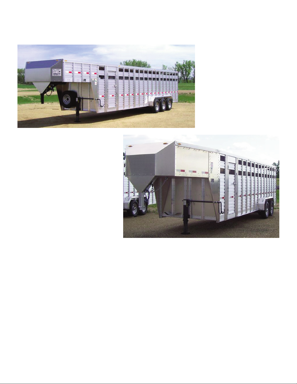
Duralite Aluminium Livestock Trailer
Introduction
To our customer:
This manual has been prepared to help you operate and maintain your new Duralite
Trailer safely. Should you have any questions, contact a Duralite factory representative
immediately for a clear explanation. We thank you for your patronage and confidence
in us through the purchase of your new Duralite Trailer.
Effective Date: April 10, 2007
1


▼ Warning ▼
DO NOT operate or service this trailer without reading and
understanding this operators manual. If manual is lost, contact the
factory for a new one.
▼ TAKE NOTE! This safety-alert symbol found throughout this manual
is used to call your attention to instructions involving your personal
safety and the safety of others. Failure to follow these instructions can
result in injury or death.
ownership of this trailer changes, this manual should accompany the
If
trailer.
Table of Contents
Description Page No.
Assistance & Reporting Safety Defects . . . . . . . . . . . . . . . . . . . . . . 26
Axle Assembly . . . . . . . . . . . . . . . . . . . . . . . . . . . . . . . . . . . . . . . . . 20
Break Operation & Trouble Shooting Guide . . . . . . . . . . . . . . . . . . .19
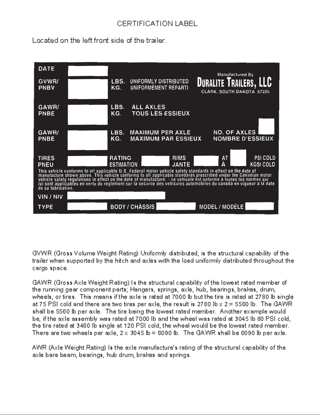
Certification Label . . . . . . . . . . . . . . . . . . . . . . . . . . . . . . . . . . . . . . . 4
Certificate of Warranty & Environmentally Consumable Goods . . . 24
Electrical Brake Assembly . . . . . . . . . . . . . . . . . . . . . . . . . . . . . .16-17
Electrical & Wiring Diagrams . . . . . . . . . . . . . . . . . . . . . . . . . . . 14-15
Extended Warranty Schedule . . . . . . . . . . . . . . . . . . . . . . . . . . . . . 25
General Specifications . . . . . . . . . . . . . . . . . . . . . . . . . . . . . . . . . . . 15
Hub & Drum Assembly . . . . . . . . . . . . . . . . . . . . . . . . . . . . . . . . . . 18
Introduction . . . . . . . . . . . . . . . . . . . . . . . . . . . . . . . . . . . . . . . . . . . . 1
Maintenance Schedule . . . . . . . . . . . . . . . . . . . . . . . . . . . . . . . . . . 12
Notice & Operating Instructions . . . . . . . . . . . . . . . . . . . . . . . . . . . . 10
Parts Lis
Pre-Trip Inspection & Maintenance Instructions . . . . . . . . . . . . . . . 11
t . . . . . . . . . . . . . . . . . . . . . . . . . . . . . . . . . . . . . . . . . . . . . 23
Safety Section . . . . . . . . . . . . . . . . . . . . . . . . . . . . . . . . . . . . . . . . 6-9
Slipper Spring Assembly . . . . . . . . . . . . . . . . . . . . . . . . . . . . . . . . . 21
Warning & Table of Contents . . . . . . . . . . . . . . . . . . . . . . . . . . . . . . . 3
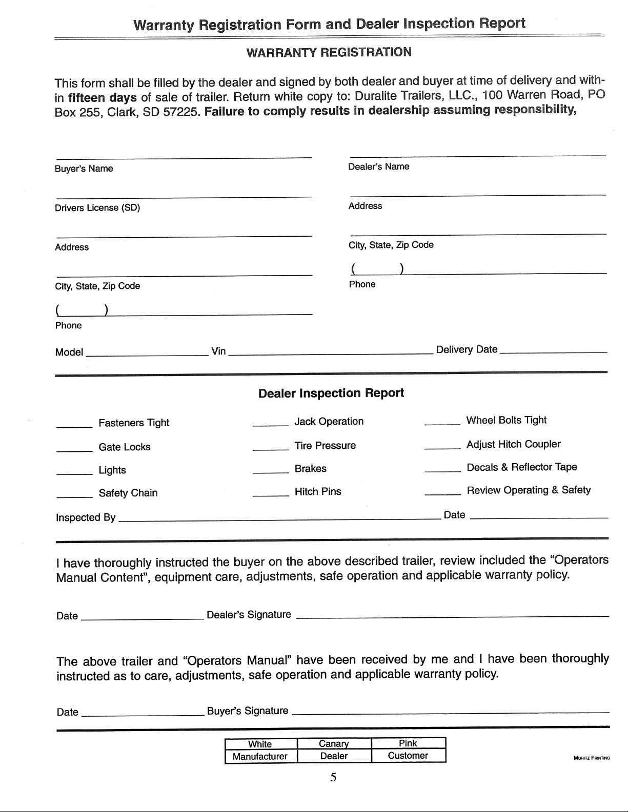
Warranty Registration Form . . . . . . . . . . . . . . . . . . . . . . . . . . . . . . . . 5
Wheel Mounting . . . . . . . . . . . . . . . . . . . . . . . . . . . . . . . . . . . . . . . . 13
3
4
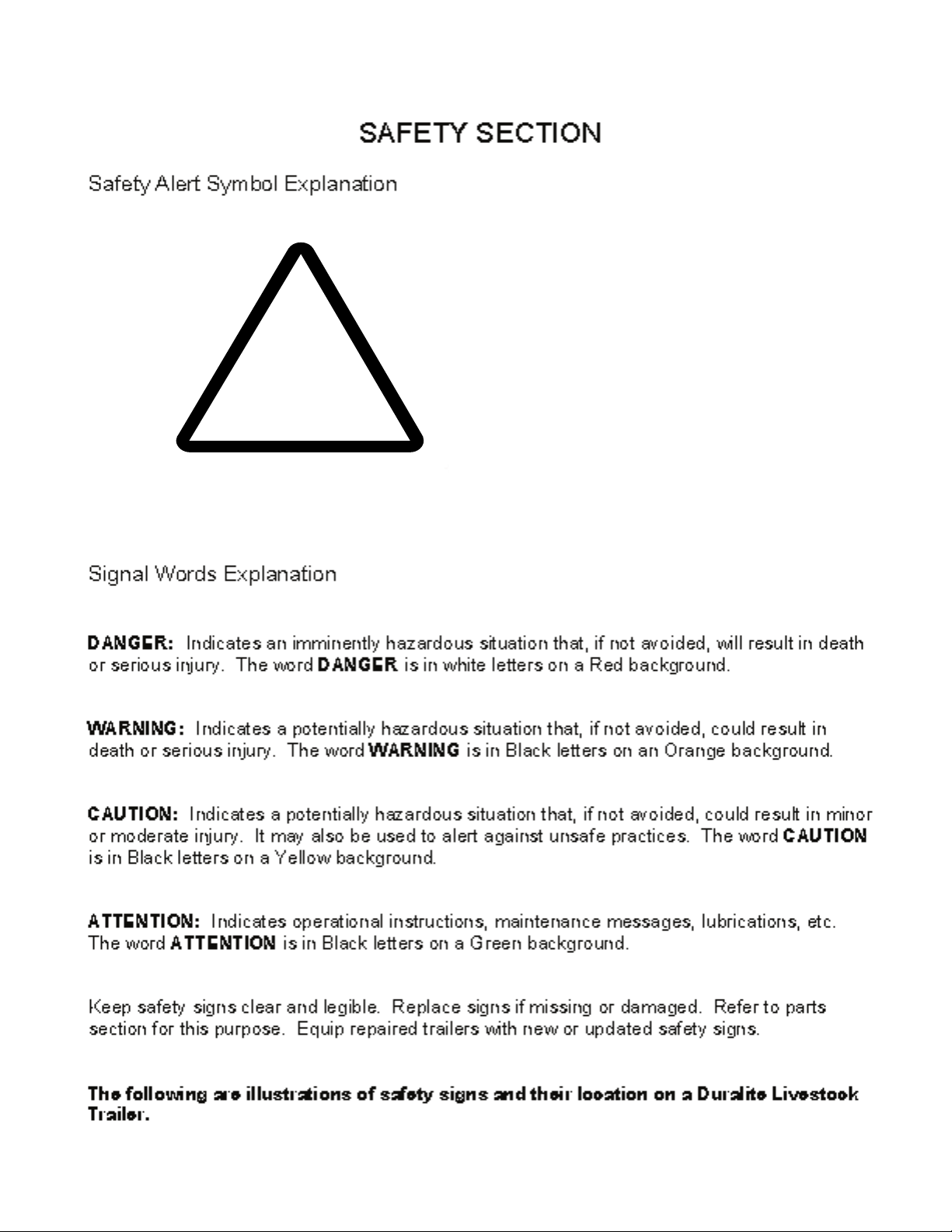
This Symbol Means
Attention!
Become Alert!
Your Saftey Is Involved
6
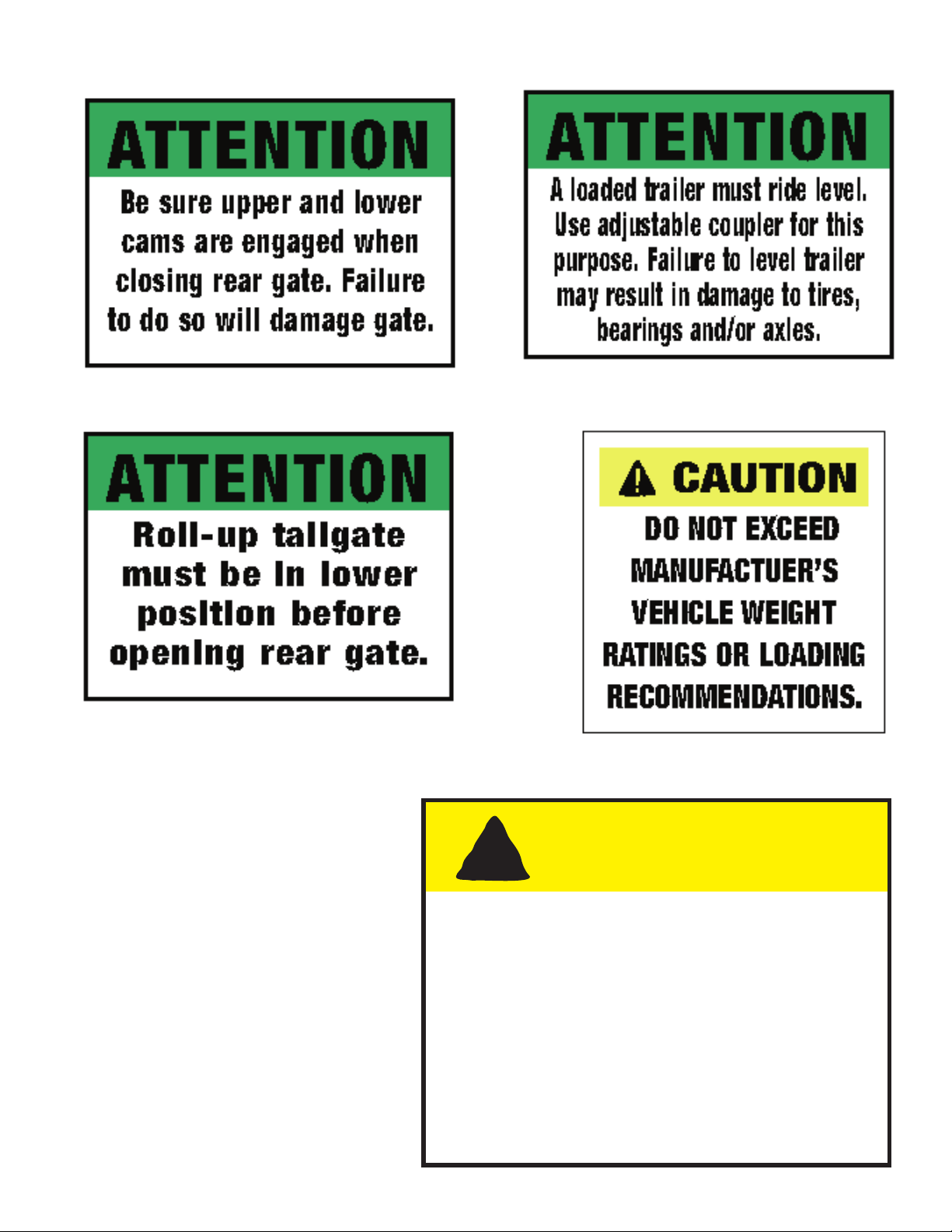
* Located on the left rear corner
!
* Located on the left front side
* Located on the left rear corner
* Located on the left front side
* Located on the left rear corner
ATTENTION
Tailgate must be in
closed position with latches
secured when trailer is in
use. Failure to do so may
result in damage to trailer
and/or injury to cargo.
7
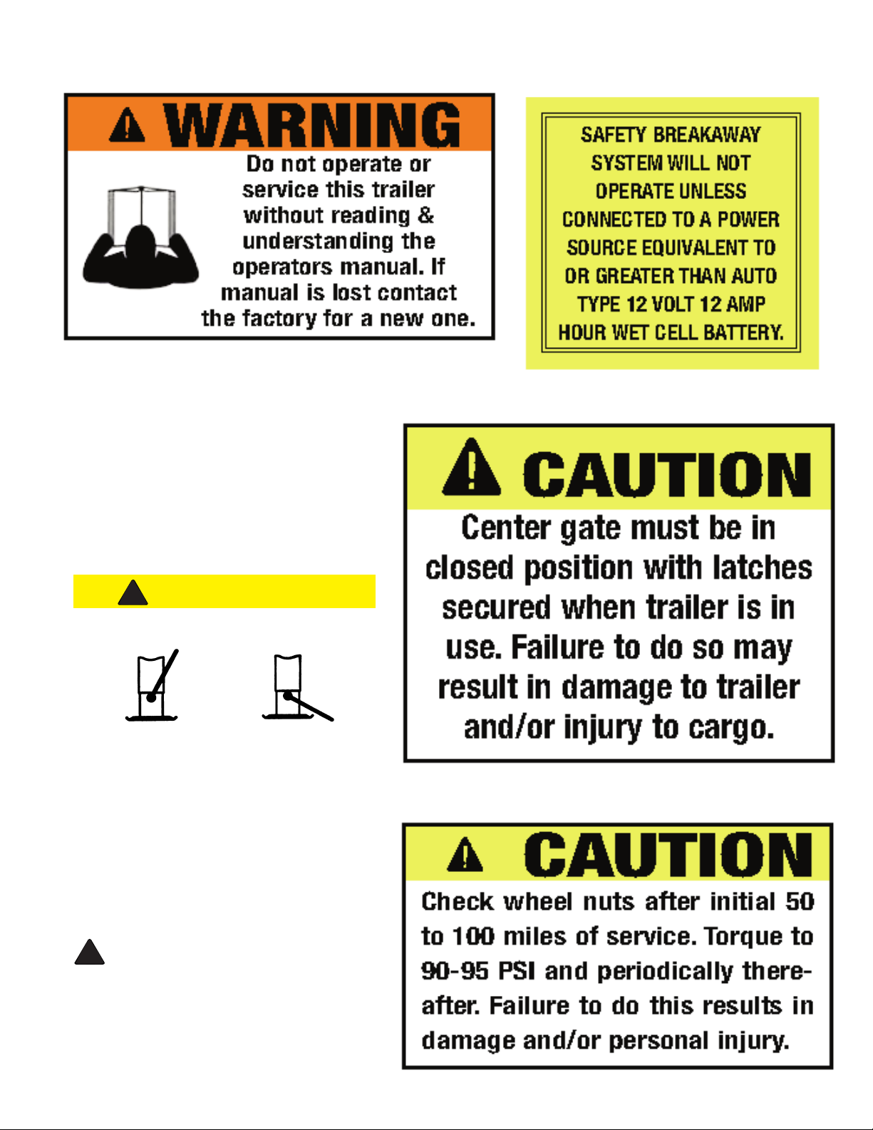
* Located on the left front side
!
!
* The following decal is vendor
supplied with their product.
* Located on Breakaway Kit
* Located on the centergate
DUAL PIN
CAUTION
U.S. PATENT NUMBER: 5,423,518
SPRING LOADED DROP LEG
LOCKED POSITION UNLOCKED POSITION
TO LOWER LEG:
1. Lower handle to released position with hand or foot.
2. Place foot on drop leg shoe and lower to desired
extension.
3. Raise handle to locked position with hand or foot, then
lift foot from shoe slowly. (Drop leg will automatically
lock in next hole position.)
4. Rotate crank to extend leg until desired height is
obtained.
TO RETRACT LEG:
1. Rotate crank to retract leg to minimum retracted
position.
WARNING: Spring force can retract drop leg with
impact. Keep hand and feet clear of impact area.
2. To raise drop leg, lower handle to released position
with hand or foot. (Drop section will automatically
retract.)
3. Raise handle to locked position with hand or foot.
* Located in center of left fender
8
 Loading...