

Page 1

Z-FLEX CURVER I
BEDIENUNGSANLEITUNG
OPERATING INSTRUCTIONS
MODE D'EMPLOI
www.dural.com
Page 2
BEDIENUNGSANLEITUNG
FÜR DEN Z-FLEX CURVER I
Mechanische Biegevorrichtung für DURAL-Abschlußprofile mit Z-FLEX-Stanzung
Mit dem Z-FLEX Curver I können DURAL-Profile mit Spezial-Z-FLEX-Stanzung, wie z.B. DUROSOL
Winkelprofile, DURAPLUS Abschlußprofile mit breiter Sichtkante, DURATRANS Transitionsprofile,
DURONDELL Viertelkreisprofile, T-FLOOR Übergangsprofile, ohne Mühe präzise gebogen werden.
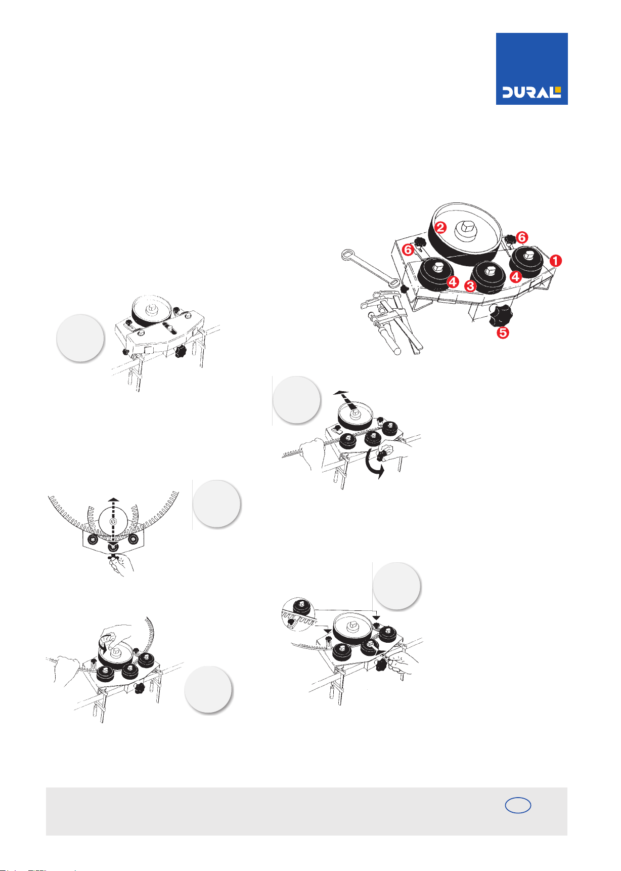
Der Z-FLEX-CURVER I besteht aus:
Der Schutzhaube der Biegescheibe verstellbar durch
den Drehknopf der verschiebbaren Führungsrolle
zwei Halterollen und zwei zusätzlichen Flachhaltern
Œ
‘
Ž
1.
Der Z-FLEX CURVER wird mit den beiliegenden Schraubzwingen unverrückbar an der Arbeitsplatte o.ä. befestigt.
3.
Durch Bewegen der BIEGESCHEIBE
mittels DREHKNOPF wird das Profil in
den gewünschten Radius vorgebogen.
5.
2.
4.
Die BIEGESCHEIBE wird mit dem
DREHKNOPF von den HALTEROLLEN
wegbewegt. Anschließend wird das
Profil eingelegt und zwar so, daß
das Profil an beiden HALTEROLLEN
anliegt. (Die ersten 15 cm werden
manuell nachgebogen oder entfernt).
Anschließend die FÜHRUNGSROLLE
mit dem beigefügten Schlüssel lockern.
Nun wird die FÜHRUNGSROLLE bis
an das Profil herangedrückt und in
dieser Position festgezogen. Dann
wird nochmals duch den DREHKNOPF
die BIEGESCHEIBE und somit auch
das Profil bis an die FÜHRUNGSROLLE
bewegt, bis eine leichte Klemmwirkung
erreicht ist. Um eine Verdrehung des
Profils und eine Beschädigung der
BIEGEROLLE zu verhindern, muß das
Profil mit den FLACHHALTERN fixiert
werden.
Durch Drehen der BIEGESCHEIBE und gleichzeitiges
Führen des Profils entsteht jetzt ein gleichbleibender Radius.
DURAL GmbH
Südring 11
D-56412 Ruppach-Goldhausen
Tel. +49 (0) 2602/9261-0
Fax +49 (0) 2602/9261-50
[email protected]
DE
www.dural.de
Page 3
BEDIENUNGSANLEITUNG
FÜR DEN Z-FLEX CURVER I
Vor der Anwendung
bitte beachten!
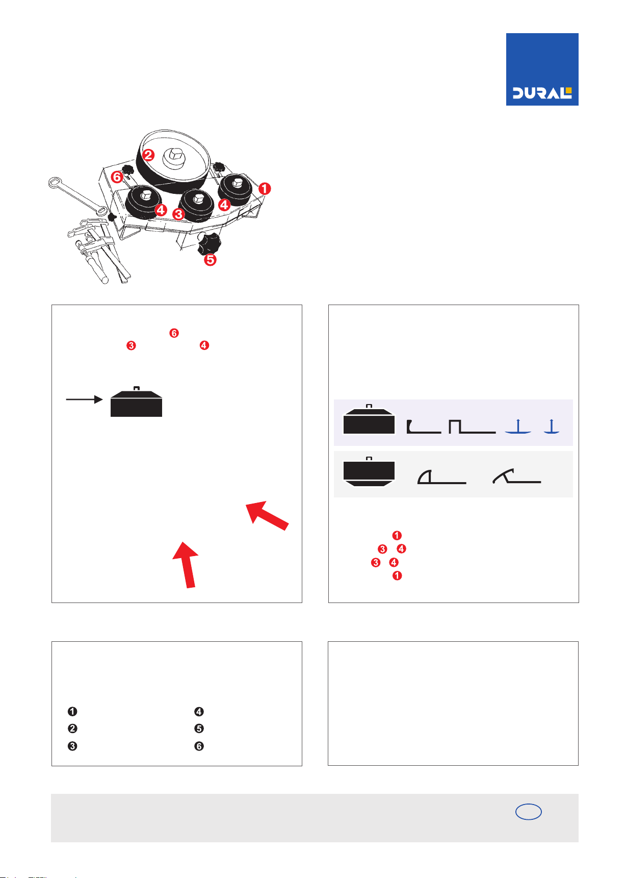
Soll das Profil mit der Stanzung nach außen gebogen werden,
müssen die zwei FLACHHALTER umgesetzt werden.
FÜHRUNGSROLLE und HALTEROLLEN müssen die
abgeschrägte Seite oben haben.
FÜHRUNGSROLLE UND HALTEROLLEN sind auf einer Seite
abgeschrägt. Für Schräg- oder Rundprofile wie DURATRANS,
DURONDELL etc. müssen die Rollen umgedreht werden (siehe Abb.)
T-FLOOR
Beim biegen mit der Sichtfläche nach unten legen.
Vorgehensweise:
- Schutzhaube entfernen (seitliche Drehknöpfe lösen)
- Muttern + mit beigefügtem Schlüssel lösen
- Rollen + umdrehen und Muttern wieder fest anziehen
- Schutzhaube bei Bedarf wieder aufsetzen und festschrauben
Der Z-FLEX Curver ist einfach in der Handhabung und wartungsfrei.
Sollte trotzdem einmal ein Teil beschädigt sein unser Ersatzteildienst
hilft schnell. Bitte geben Sie folgende ET-Nr. an:
Schutzhaube Nr. 08 125 001
Biegescheibe Nr. 08 125 002
Führungsrolle Nr. 08 125 003
DURAL GmbH
Südring 11
D-56412 Ruppach-Goldhausen
Halterolle Nr. 08 125 003
Drehknopf Nr. 08 125 005
Flachhalter Nr. 08 125 006
Tel. +49 (0) 2602/9261-0
Fax +49 (0) 2602/9261-50
[email protected]
Bitte beachten:
Bei den unterschiedlichen Profilen kann sich der Radius
bei gleicher Einstellung verändern. Deshalb können auf der Skala
nur Anhaltswerte angegeben werden. Durch den wiederholten
Biegevorgang und gleichzeitigem Nachstellen der FÜHRUNGSROLLE wird der gewünschte Radius durch "heranarbeiten" erzielt.
DE
www.dural.de
Page 4
OPERATING INSTRUCTIONS
For THE Z-FLEX CURVER I
The hand operated mechanical bending machine for DURAL profiles that have
the Z-FLEX punched flange.
Using the Z-FLEX CURVER I it is possible to simply bend a range of DURAL profiles that incorporate
the Z-FLEX punched flange. These special profiles include DUROSOL, DURAPLUS, DURONDELL,
DURATRANS and T-FLOOR.
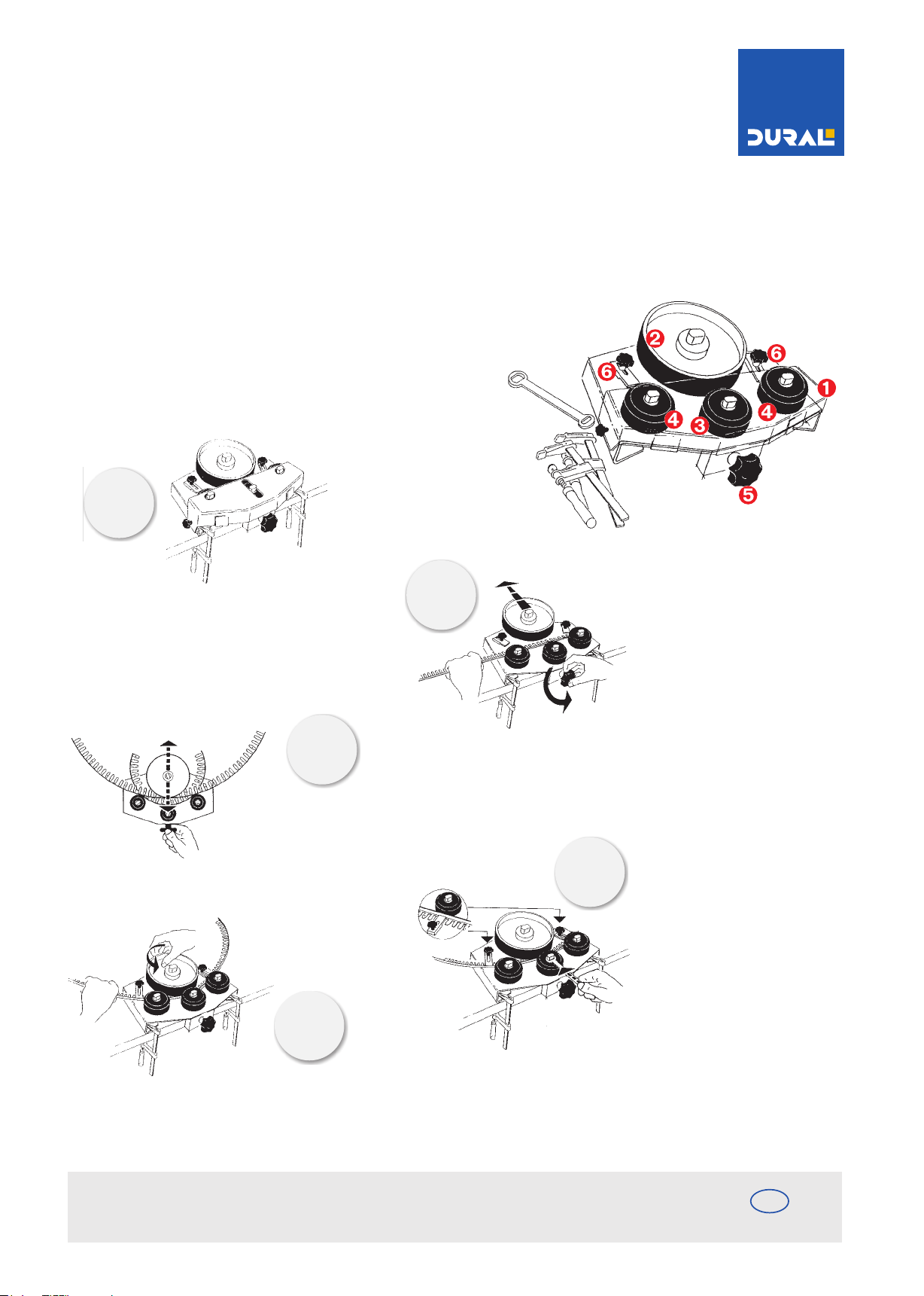
The Z-FLEX CURVER I consists of:
The protective hood, the bending wheel, adjustable
with the turning knob, the moveable guide wheel, two
holding wheels, and two additional flat holding clamps
Œ
Ž
‘
1.
Z-FLEX CURVER can easily be secured to a bench or work
surfaces using the two CLAMPS.
3.
By turning the FRONT KNOB, the large
BENDING WHEEL allows the profile to
bend to the desired radius.
5.
2.
4.
Firstly remove the PROTECTIVE HOOD.
The large BENDING WHEEL is made to move
forward and back when turning the FRONT
KNOB. The two HOLDING WHEELS, including
the two small additional FLAT HOLDING CLAMPS,
act as the guide when the profile is placed in
the Z-FLEX CURVER. The first 15 cm allow for
the profile to be bent manually or removed.
However, should the distance be over 15 cm
it is necessary to adjust the MOVEABLE GUIDE
WHEEL, using the key provided.
When the profile is placed into the Z-FLEX CURVER,
the two GUIDE WHEELS (4) are pressed against the
profile and held in the desired position.
By turning the FRONT KNOB (5), the LARGE
BENDING WHEEL (2) is moved towards the two
GUIDE WHEELS (4), claiming the profile in
position. To avoid too much tension of the profile
and possible damage to the LARGE BENDING
WHEEL (2), the profile must be secured using the
two FLAT HOLDING CLAMPS (6).
By turning the large BENDING WHEEL, and simultaneously guiding
the profile, you can now produce the required radius as desired.
DURAL GmbH
Südring 11
D-56412 Ruppach-Goldhausen
Tel. +49 (0) 2602/9261-0
Fax +49 (0) 2602/9261-50
[email protected]
EXP
www.dural.com
Page 5
OPERATING INSTRUCTIONS
For THE Z-FLEX CURVER I
Before use,
pay attention!
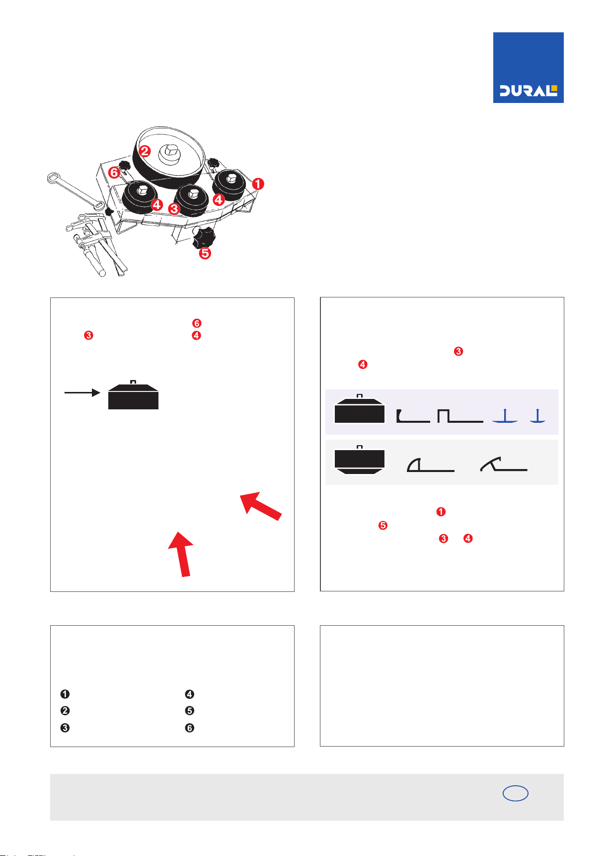
Should it be necessary to bend the profile to the outside you will need
to relocate the two FLAT HOLDING CLAMPS . The MOVEABLE GUIDE
WHEEL and the two HOLDING WHEELS have to have the bevelled
side to the top. You will see in the diagram that these three wheels all
have just one side bevelled.
Profiles including DUROSOL, DURAPLUS and T-FLOOR can be bent using the
Z-FLEX CURVER machine in its normal setting without turning over the three
wheels. When using profiles such as DURATRANS and DURONDELL it will be
necessary for the MOVEABLE GUIDE WHEEL and the two HOLDING
WHEELS to be turned over thus exposing their bevelled side.
T-Floor (For bending to be placed to the lower side)
Procedure:
- Firstly remove the PROTECTIVE HOOD by slackening the front
TURNING KNOB .
- Slacken the nuts on the three WHEELS and, using the key provided.
- Turn these wheels over so that they are upside down, then re-tighten
the nuts using the key. Replace the PROTECTIVE HOOD if necessary
and secure with screws.
The Z-FLEX CURVER is simple to operate and maintenance-free, however we do recommend
that you clean the machine after use. Should you happen to loose or damage any of the parts
of the CURVER we are pleased to offer a range of spares. The parts available are as follows:
Protectiv hood no. 08 125 001
Bending wheel no. 08 125 002
Moveable no. no. 08 125 003
DURAL GmbH
Südring 11
D-56412 Ruppach-Goldhausen
Holding wheels no. 08 125 003
Tuning knob no. 08 125 005
Flat holding clamp no. 08 125 006
Tel. +49 (0) 2602/9261-0
Fax +49 (0) 2602/9261-50
[email protected]
Attention!
As some of the DURAL profiles are different in shape and configuration it is
possible that the radius required can be different using the same adjustment
by repeating the bending process using different profiles and simultaneously
adjusting the two MOVEABLE GUIDE WHEELS, the desired radius is achieved
by "approximation".
EXP
www.dural.com
Page 6
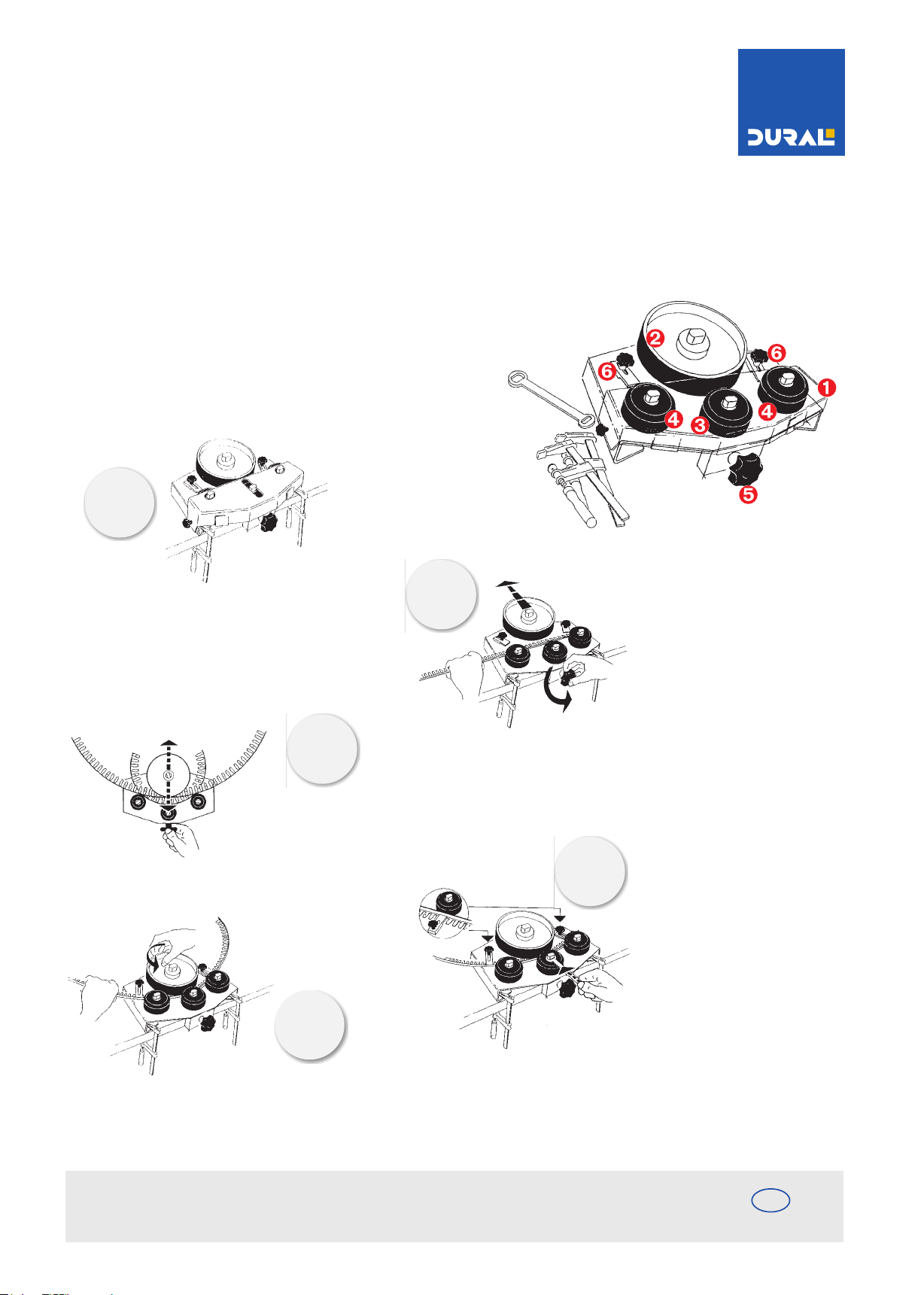
MODE D'EMPLOI LE Z-FLEX CURVER I
Cintreuse mécanique pour profilés DURAL à embase Z-FLEX.
Avec le Z-FLEX CURVER I il est possible de plier avec simplicité et grande précision les profilés DURAL à perforation Z-FLEX
tels que les profilés de finition chant droit DUROSOL, les profilés de raccordement à large bordure DURAPLUS, les
profilés de transition DURATRANS, les profilés de finition arrondis DURONDELL ou les profilés de recouvrement T-FLOOR.
Le Z-FLEX-CURVER I se composé des éléments suivants:
CAPOT DE PROTECTION DISQUE DE PLIAGE
réglable au moyen du BOUTON POULIES DE GUIDAGE
réglables deux POULIES DE MAINTIEN
et deux ERGOTS DE MAINTIEN supplémentaires.
Ž
Œ
‘
1.
Fixer solidement le Z-FLEX CURVER sur la table de travail
ou sur l'établi au moyen des serre-joints fournis.
3.
Plier le profilé au rayon désiré par
déplacement du DISQUE DE PLIAGE
à l‘aide du BOUTON.
5.
2.
4.
Décaler le DISQUE DE PLIAGE des
POULIES DE MAINTIEN à l'aide du
BOUTON deréglage. Mettre ensuite
le profilé en place de sorte qu'il
vienne buter contre les deux POULIES
DE MAINTIEN (les premiers 15 cm
sont introduits à la main ou supprimés).
Désserrer la POULIE DE GUIDAGE à
l’aide de clé fournie.
Presser la POULIE DE GUIDAGE
contre le profilé et serrer. A l‘aide
du BOUTON, déplacer maintenant
le DISQUE DE PLIAGE, et aussi le
profilé, contre la POULIE DE
GUIDAGE jusqu‘à obtenir un léger
pincement. Fixer le profilé à l‘aide
des ERGOTS DE MAINTIEN pour
empêcher son vrillage ou
l‘endommagement du DISQUE DE
PLIAGE.
Tourner le DISQUE DE PLIAGE et guider en même
temps le profilé pour le plier au rayon désiré.
DURAL SAS
27, Rue du Champ de Mars
F-57200 Sarreguemines
Tel.: 00.49.26.02.92.61.615/616
Fax: 00.49.26.02.92.61.803
[email protected]
FR
www.dural.fr
Page 7
MODE D'EMPLOI LE Z-FLEX CURVER I
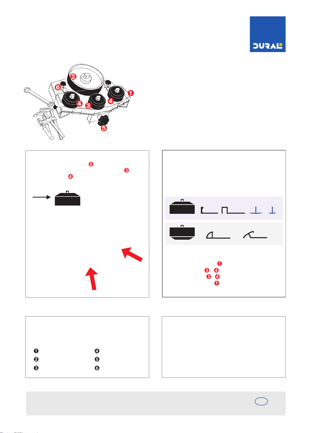
Avant l'utilisation de
la cintreuse. Merci de !
Lorsque le profilé doit être plié avec la preforation orientée vers
l‘extérieur, les deux ERGOTS PLATS DOIVENT auparavant être
retournés. Le côté‚ chanfreiné‚ de la POULIE DE GUIDAGE et des
POULIES DE MAINTIEN DOIT être orient‚ vers le haut.
La POULIE DE GUIDAGE ET DE MAINTIEN sont chanfreinées sur un
des côtés. Les poulies doivent être retournées pour le pliage de
profilés ronds ou de finition DURATRANS ou
T-FLOOR
Côté visible vers le
bas pour le pilage.
Procédure:
- Retirer le capot de protecion (desserrer les boutons latéraux)
- Desserrer les ècrous + à L'aide de la clé fournie
- Retourner les poulies + puis resserrer les écrous
- Si besoin, remette le capot en place et le refixer
Le Z-FLEX CURVER est facile à utiliser et ne nécessite aucun entretien.
Toutefois, si une pièce est défectueuse notr service aprés-vente vous
dépannera rapidement si vous lui indiquez le numéro de la
pièce concernée:
Capot de protection No. 08 125 001
Disque de pliage No. 08 125 002
Poulie guidage No. 08 125 003
DURAL SAS
27, Rue du Champ de Mars
F-57200 Sarreguemines
Poulie de maintien No. 08 125 003
Bouton No. 08 125 005
Ergot de maintien No. 08 125 006
Tel.: 00.49.26.02.92.61.615/616
Fax: 00.49.26.02.92.61.803
[email protected]
Attention!
Avec le même réglage, il est possible que le rayon diffère selon le
profilé plié. Par conséquent, les indications sur les cadrans ne sont
qu'approximatives. Le rayon désiré est obtenu par pliage répété
et réglage succéssif de la POULIE DE GUIDAGE.
FR
www.dural.fr
Page 8

www.dural.com
 Loading...