

DURAG D-FL 200 Owner's Manual

07/00 Rev. 6
DURAG
Industrie Elektronik GmbH & Co KG
Kollaustraße 105 · D-22453 Hamburg · Tel. +49 40 554218-0 · Fax +49 40 584154
D-FL 200
Ultrasonic Flow Monitor

D-FL 200 / Rev. 6
______________________________________________________________________________________________________
Industrie Elektronik GmbH & Co KG
Table of Contents
1. Application.........................................................................................................................................1
2. Function .............................................................................................................................................1
3. System Components.........................................................................................................................6
3.1. Evaluation Unit D-FL 200-10......................................................................................................7
3.2. Transducer .................................................................................................................................8
3.3. Purge Air System........................................................................................................................9
4. Choosing the Measuring Point ......................................................................................................12
5. Electrical Connection D-FL 200......................................................................................................13
5.1. Electrical Connection of the D-FL200-10 Evaluation Unit ........................................................13
5.2. Electrical Connection of the D-FL200-20 Transducers ............................................................15
6. Measuring Sequence.......................................................................................................................16
6.1. Self-Check................................................................................................................................16
6.2. Calibration Cycle....................................................................................................................16
6.2.1. Zero Test......................................................................................................................16
6.2.2. Span Test.....................................................................................................................16
6.3. Monitoring.................................................................................................................................16
7. Registration of Measured Values...................................................................................................16
8. Operating the D-FL 200-10 Evaluation Unit ..................................................................................17
8.1. Key Functions 21
8.2. Storing / Entering Parameters by using the Keys....................................................................21
8.3. Storing / Entering Parameters via the RS232 Interface ..........................................................21
9. Installation.........................................................................................................................................22
9.1. Mounting the Welding Flanges..................................................................................................22
9.2. Installation of the purge air system...........................................................................................23
9.3. Installation of the sensor units D-FL 200-MK ...........................................................................23
9.4. Installation of the evaluation unit D-FL 200-10.........................................................................23
9.5. Start up of the evaluation unit D-FL 200-10..............................................................................24
10. PC-Parameterisation of the D-FL 200COM..................................................................................25
10.1. Installation of the program......................................................................................................25
10.2. Connecting the D-FL 200 system and the PC........................................................................25
10.3. Parameterisation Program D-FL 200COM.............................................................................25
10.3.1. First Page / Main........................................................................................................25
10.3.2. Second Page / Parameter..........................................................................................26
10.3.3. Third Page / Measuring..............................................................................................29
10.3.4. Fourth Page / Signal...................................................................................................31
11. Error Messages..............................................................................................................................32
12. High temperature applications......................................................................................................33
13. Maintenance....................................................................................................................................34
14. Scope of delivery / standard system............................................................................................35
15. Technical Data ...............................................................................................................................38
Transducers .....................................................................................................................................38
Purge air unit “G” for gas above dew point.......................................................................................39
16. Measuring Point Questionnaire ...................................................................................................40

D-FL 200 / Rev. 6
______________________________________________________________________________________________________
Industrie Elektronik GmbH & Co KG
Illustrations
(Fig. 1) Measuring principle.....................................................................................................................2
(Fig. 2) Plane through the pipe axis (standard) .......................................................................................3
(Fig. 3) Consideration of the flow profiles................................................................................................4
(Fig. 4) Measurement independent of the flow profile (optional).............................................................4
(Fig. 5) System components....................................................................................................................6
(Fig. 6) Basic diagram of the microprocessor unit...................................................................................7
(Fig. 7) Dimensions of the D-FL 200-10 evaluation unit..........................................................................8
(Fig. 8) Dimensional drawing of the transducer.......................................................................................8
(Fig. 9) D-FL 200 flange ..........................................................................................................................9
(Fig. 10) Electrical connection of the purge air system..........................................................................10
(Fig. 11) Electrical connection 3-phase power supply 230V..................................................................10
(Fig. 12) Electrical connection 3-phase power supply 400V..................................................................11
(Fig. 13) Dimensional drawing of the purge air system .........................................................................11
(Fig. 14) Measurement in a plane through the pipe axis, standard.......................................................12
(Fig. 15) Measurement in two planes offset from the pipe axis, optional ..............................................13
(Fig. 16) Terminal strip on the housing..................................................................................................14
(Fig. 17) Layout of the transducer plug..................................................................................................15
(Fig. 18) Layout of the terminal strip on the sensor board.....................................................................15
(Fig. 19) Front panel of the D-FL 200-10 evaluation unit.......................................................................17
(Fig. 20) Recommended installation of the D-FL 200 welding flanges..................................................22
(Fig. 21) Recommended installation of the D-FL 200 welding flanges..................................................23
(Fig. 22) First page / Main .....................................................................................................................26
(Fig. 23) Second page / Parameter .......................................................................................................27
(Fig. 24) Third page / Measuring ...........................................................................................................30
(Fig. 25) Fourth page / Signal................................................................................................................31
(Fig. 26) Measuring in high temperature applications ............................................................................34
Revision : 6
Document : D-FL200-e.doc
Issue : July-2000
Software : FL1.4 or higher
Print date : 31 July 2000

D-FL 200 / Rev. 6 1
______________________________________________________________________________________________________
Industrie Elektronik GmbH & Co KG
1. Application
Acoustic methods of f low measurement use sound waves to determine velocity and flow. The pulse
differential method is am ong the bes t k nown and reliable of suc h m ethods. High res olution is achieved
using frequencies in the ultrasonic range.
This monitoring system is applicable in acquiring flue gas volumetric flow in combustion or waste
incineration systems. The system also allows measurements to be made that are otherwise poorly
performed using traditional systems. Measurements in lower velocity ranges are also possible, in
contrast to differ ential pressure methods. This system is especially advantageous due to its ease of
installation, even on stacks that are wide in diameter.
Acquisition of volumetric f low occurs along the entire pr ofile of the f low. The essential advantage of an
ultrasonic monitoring system is that neither temperature, press ure nor density changes will influence
the measured result. If you want receive the standard volum etric flow you have to consider these three
parameters.
The system is designed for veloc ities of 0-40 m/s ( 0-131 ft/sec.) and stac k diameters till 5 m (197 in.)
with it measurements up to 0-5,000,000 m³/h (0-approx. 17,7*10
7
ft3/h) are possible.
2. Function
The measurement of volumetric flow using ultrasonic probes offers great advantages compared to
conventional methods using diff erential pressure, since this type of system operates with no moving
parts. Conventional screens heavily choke the overall f low and cause pressure losses. This causes
high energy costs. The em ployment of dynamic pr essur e probes r equires the us e of expens ive special
materials if the stack gas is heavily corrosive. In contrast, purge air is used to separate ultrasonic
sensors from the stack gas.
The monitoring s ystem oper ates using two ultras onic trans duc ers , which c an both trans mit and receive
acoustic signals. T hes e tr ansduc er s ar e ins talled in a s tack such that the velocity of the acoustic signal
is influenced by the gas flow. That is to say, the gas flow must show properties of a vectorial portion in
the direction of the acoustic signal (see
(Fig. 1) Measuring principle
). The ultrasonic sensors are
installed at an angle of about 45° (range 30° - 60°) to the axis of the stack. The trans it times of the
acoustic impulses f orm the basis of the volum etric flow and velocity calculations.
(Fig. 1) Measuring
principle
offers a schem atic of the monitoring system. The transmitting oscillator receives a keyed
sinusoidal signal and transforms it into an acoustic wave pack whose transit time through the gas
medium is measured. The transit times result as follows:
+
=
+⋅
t
L
(c v co s )
α
Equation 1
−
=
⋅
t
L
(c- v cos )
α
Equation 2
with: t
+
Impulse transit time with the flow
t
-
Impulse transit time against the flow
c Sonic velocity

D-FL 200 / Rev. 6 2
______________________________________________________________________________________________________
Industrie Elektronik GmbH & Co KG
v Gas velocity
L Measuring path in the medium
α Angle of installation
(Fig. 1) Measuring principle
The two equations shown before for im pulse transit times m ay be reduced down for sonic velocity ‘c’
and gas velocity ‘v’:
c
L2tt
tt
=⋅
+
⋅
−+
−+
Equation 3
v
L
2cos
tt
tt
=
⋅
⋅
+
⋅
−+
−+
α
Equation 4
The speed of the sound changes with the temperature of the gas according to the next formula.
whereby T is in Kelvin. With this equation the gas temperature can be obtained from the measurement.
K
T
273s
m
331,6 c
⋅=
Gl.5
D-FL 200 / Rev. 6 3
______________________________________________________________________________________________________
Industrie Elektronik GmbH & Co KG
Volumetric flow may be obtained using the following formula:
QkAv=⋅⋅
Equation 6
with: K Correction factor
A Stack diameter
Since each stack develops its own particular velocity distribution, the m ean velocity is determined for
calculation of the volumetric flow. If the flow were completely laminar, a single spot measurement
would suffice. The ac oustic im pulse method enables a c ross-sec tional measurem ent to be made over
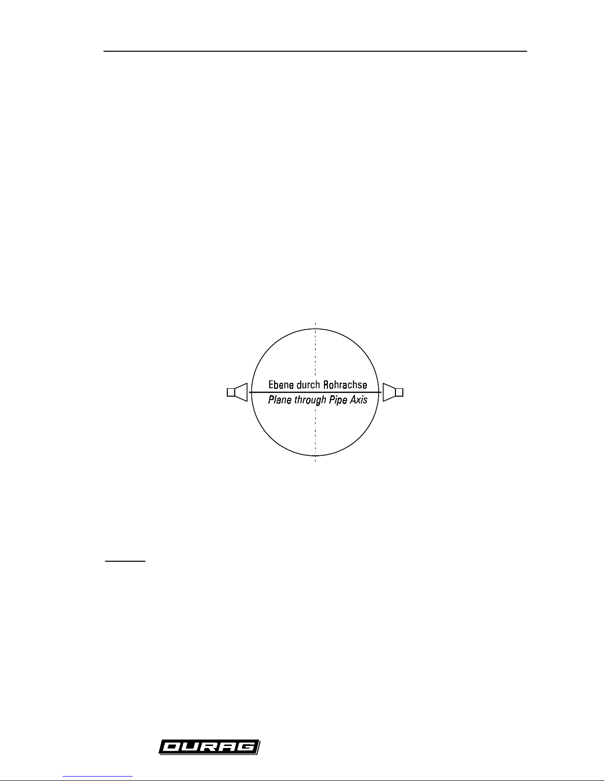
the entire diameter of the stack . If the ultrasonic s ensors are arranged in a plane through a pipe axis,
as shown in
(Fig. 2) Plane through the pipe axis (standard)
, the measured velocity must be weighted
according to the geometry of the pipe.
(Fig. 2) Plane through the pipe axis (standard)
If flow velocity lies in the lower range, the correction fac tor is 0.75 for cylindrical stacks and 0.66 for
square stacks. If it is technically feasible to do so, a calibration should be performed in such an
installation.
Optional:
An alternative installation is one in which the ultrasonic transduc ers are installed in one or two planes
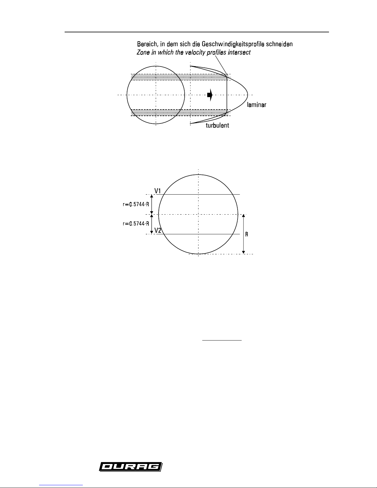
which do not run through the pipe axis. This arrangement is shown in
(Fig. 4) Measurement
independent of the flow profile (optional).
This setup is advantageous since the influence of the flow
profile on the measured res ult is minimized. This is shown schematically in
(Fig. 3) Consideration of
the flow profiles
. The measuring planes must lie in zones which intersect the variable velocity curves.
D-FL 200 / Rev. 6 4
______________________________________________________________________________________________________
Industrie Elektronik GmbH & Co KG
(Fig. 3) Consideration of the flow profiles
(Fig. 4) Measurement independent of the flow profile (optional)
As shown in
(Fig. 4) Measurement independent of the flow profile (optional)
the measuring planes
must be arranged at a distance of r = 0.5774*R from the pipe axis. The correction factor is k=1.
The volumetric flow is determined using four ultrasonic transducers in two planes:
QkA
(v1 v2)
2
=⋅⋅
+
Equation 7
If only two ultrasonic transducers are used in a plane off set from the pipe axis, the volumetr ic flow is
determined as follows:
QkAv1
=⋅⋅
Equation 8

D-FL 200 / Rev. 6 5
______________________________________________________________________________________________________
Industrie Elektronik GmbH & Co KG
In general, the meas urement should result in the s tandard volum etric flow. This requires the f ollowing
conversion:
QQ
PPT
T
n
n
n
=⋅ ⋅
Equation 9
with: P Absolute pressure [hPa]
P
n
Standard pressure = 1013 hPa
T Temperature [K]
T
n
Standard temperature [K]
D-FL 200 / Rev. 6 6
______________________________________________________________________________________________________
Industrie Elektronik GmbH & Co KG
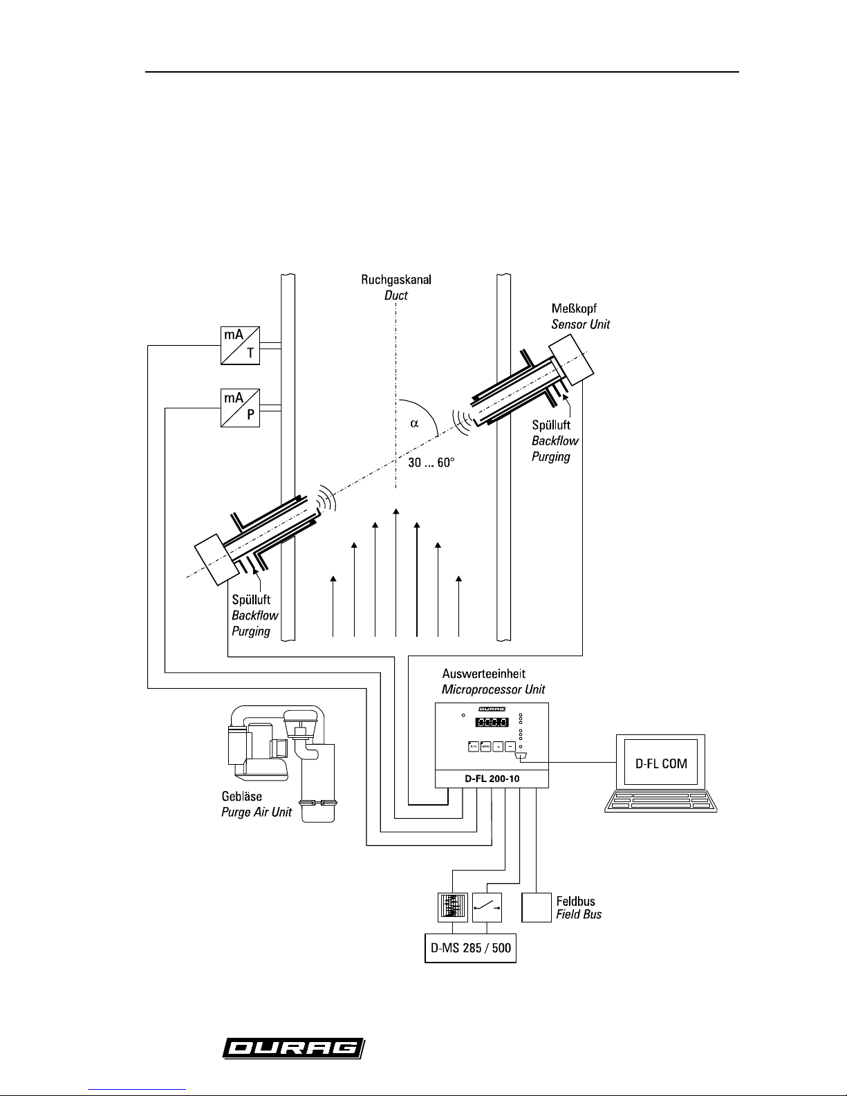
3. System Components
The D-FL 200 Ultrasonic Flow Monitor consists of the following components:
• D-FL 200-10 evaluation unit
• two or (optional) four D-FL200-MK ultrasonic transducers
• purge air unit
• temperature measurement (optional)
• absolute pressure measurement (optional)
(Fi g. 5) System components
D-FL 200 / Rev. 6 7
______________________________________________________________________________________________________
Industrie Elektronik GmbH & Co KG
Temperature and absolute pres sure measurements are required for converting the volumetr ic flow to
standard volumetric flow. Alternatively these quantities can be program med into the evaluation unit as
constants. Two 4-20 mA inputs f or absolute press ure and temperature m easurem ents are provided in
the evaluation unit. Existing equipment can simply be looped in.
The ultrasonic sensors do not come into contact with the stack gas. In particular, the build-up of
condensate is prevented. The purge air s ystem is s pec ially designed for this and has a negligible effect
on the ultrasonic signal.
The transducers are exclusively supplied with auxiliary power from the evaluation unit. The
piezoelectric ultrasonic sensors are ruggedly built and are designed to withstand environmental
conditions.
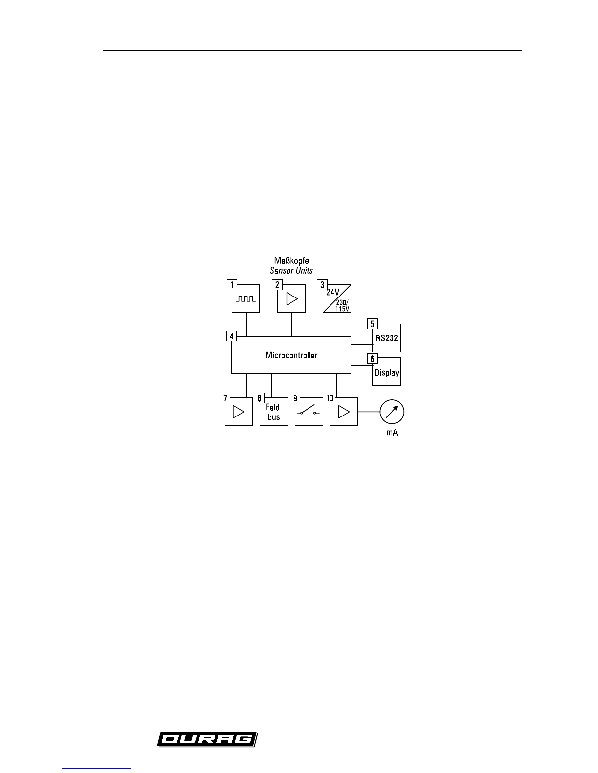
3.1. Evaluation Unit D-FL 200-10
Two or (optional) f our transducers m ay be connected to the evaluation unit. The block diagram below
depicts the operations of the unit.
(Fig. 6) Basic diagram of the microprocessor unit
1. Drive sensors
2. Sensor signal amplification
3. Auxiliary power for the transducers
4. Algorithms for assessment of measured values
5. RS232 interface
6. Display output function
7. mA inputs
8. Field bus communications interface (optional)
9. Limit value and state contacts
10. mA outputs
D-FL 200 / Rev. 6 8
______________________________________________________________________________________________________
Industrie Elektronik GmbH & Co KG
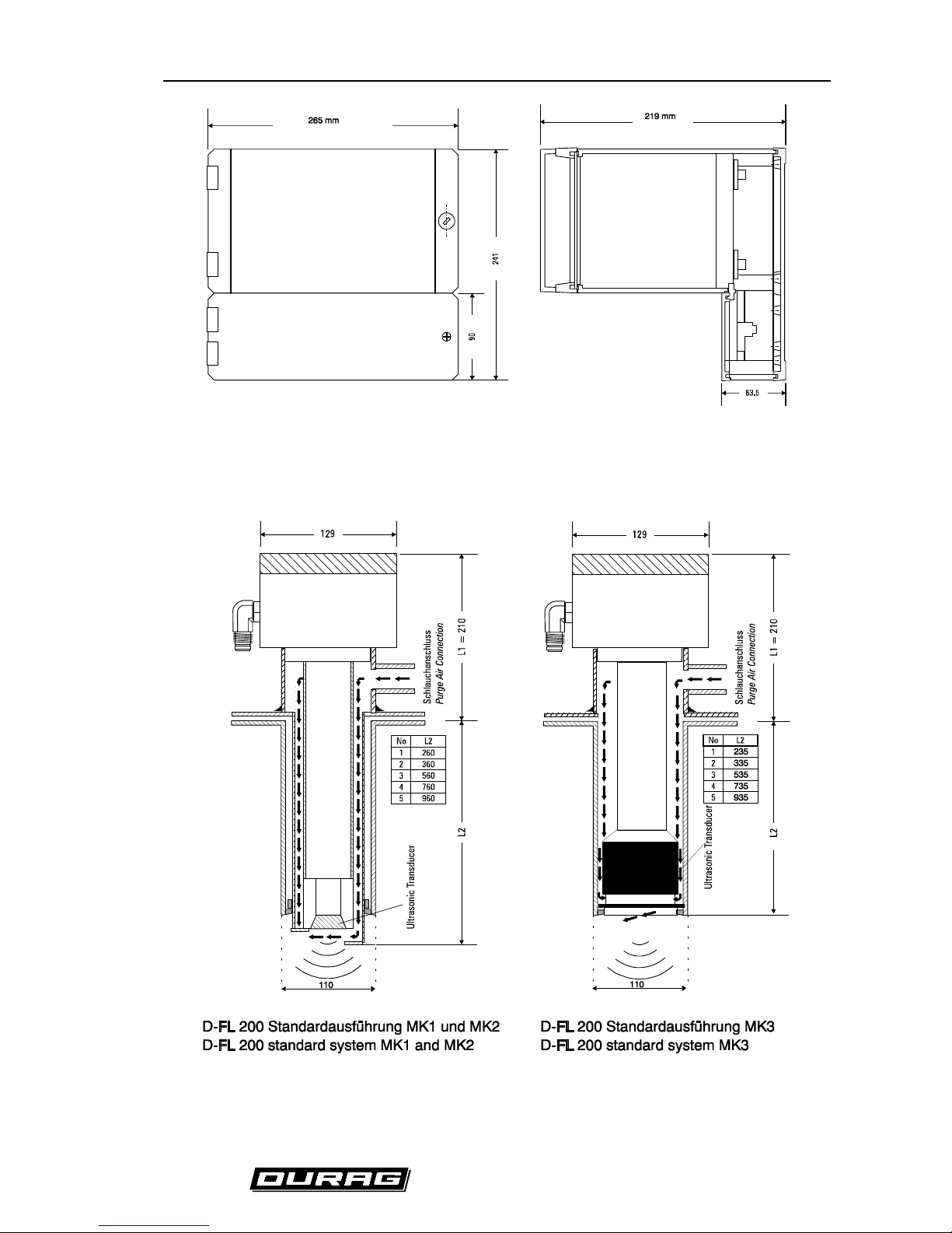
(Fig. 7) Dimensions of the D-FL 200-10 evaluation unit
3.2. Transducer
The transducer consists of the ultrasonic sensor, sensor electronics and welding flange.
(Fig. 8) Dimensional drawing of the transducer
D-FL 200 / Rev. 6 9
______________________________________________________________________________________________________
Industrie Elektronik GmbH & Co KG
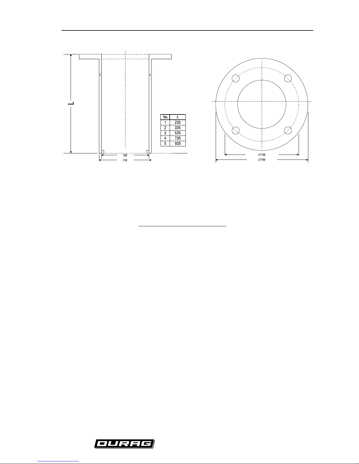
(Fig. 9) D-FL 200 flange
The required minimum length of the welding flanges can be obtained from the next equation:
L
(20 D 150 cos )
sin
W
=
++⋅
α
α
Equation 9
with: L Length of the flanges [mm]
D
W
Wall thickness of the duct [mm]
3.3. Purge Air System
The use of a purge air system helps to prevent the surfaces from getting dirty prematurely and also
protect the system against the heat of the flue gas. If a purge air system is not us ed, the monitoring
system may suffer from excessive dirt accumulation in applications where negative pressure is
prevalent. This is especially true if the boiler is shut down, absenc e of an upward draft and during startup phase.
The following points should be considered when selecting a location to mount the purge air system:
•
The intake air must be as dry and dust-free as possible.
•
The temperature of the intake air may be a maximum of 313 K (104°F/40°C).
•
When mounting the system, the filter has to be vertical. The dust valve must situated at the
bottom.
•
Adequate space must be left for exchanging the filter (see page 11).
If the purge air system is being mounted outdoors, the weather hood D-WSH 290 GN is available.
D-FL 200 / Rev. 6 10
______________________________________________________________________________________________________
Industrie Elektronik GmbH & Co KG
Caution!
The following must be observed during the electrical installation of the
D-FL 200:
• The installation may be done only by a skilled worker.
• Before performing any work on the system, it must be disconnected from the power supply.
• The power supply and frequency has to correspond with the information shown on the nameplate.
• Connections must be made as shown on the wiring diagram on the cover of the terminal strip.
• The grounded lead must be connected to the ground terminal.
• The motor safety switch (not included) must be set to the rated current of the motor.
• The direction of rotation of the motor must be checked (Arrow on the cover).
• Ensure a s eparate power supply for the purge air system, because the purge air has to blow all
the time.
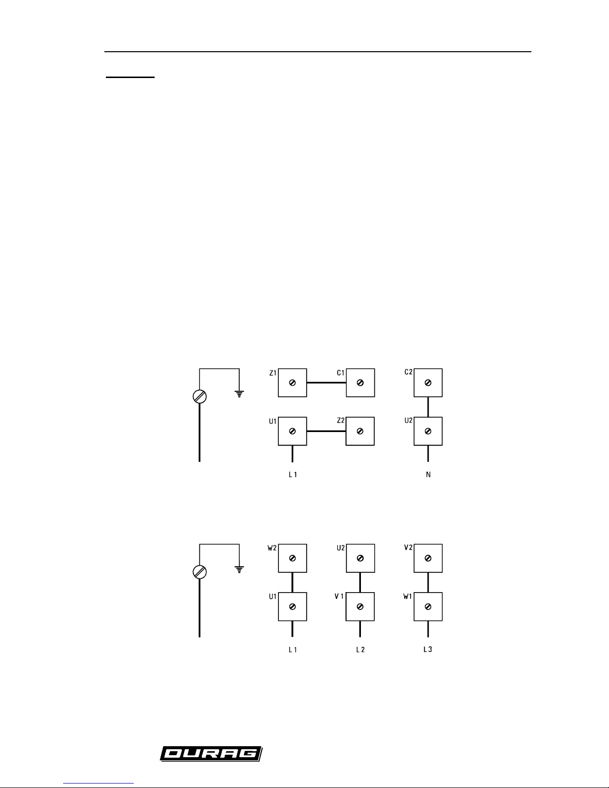
Use the wiring diagram as shown in
(Fig. 10) Electrical connection of the purge air system
if your
power supply is single phase. In the case of using three-phase power s upply you must connect your
motor according to
(Fig. 11) Electrical connection 3-phase power supply 230V
and
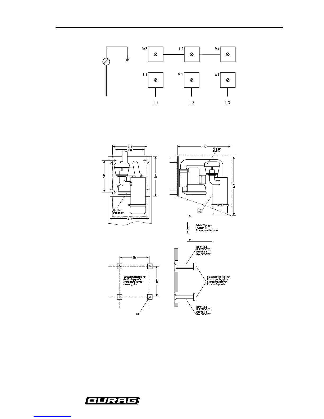
(Fig. 12) Electrical
connection 3-phase power supply 400V.
Use
Fig. 11
if you supply with 200V - 240V. If you supply with
345V - 415V than connect the motor according to
Fig. 12.
Erde
Ground
(Fig. 10) Electrical connection of the purge air system
Erde
Ground
(Fig. 11) Electrical connection 3-phase power supply 230V
D-FL 200 / Rev. 6 11
______________________________________________________________________________________________________
Industrie Elektronik GmbH & Co KG
Erde
Ground
(Fig. 12) Electrical connection 3-phase power supply 400V
(Fig. 13) Dimensional drawing of the purge air system
 Loading...