

Page 1
INSTRUCTIONS FOR ZEPHYR V-70 EDF-EPO
Warning: This aircraft is a hobby grade product, only for people of 14 years of
age or above.
Please read and underst and all instructions before opeating.
Features:
1)This product features the updated aerodynamic design, fulfilling a perfect c
ombination with installation of EDF , which is therefore considered as the hig
h-speed glider plane.
2) Bilateral air intakes allows for reliable ventilation,keep the edf perfect blend
in the side of body.
3) The 70mm EDF providing the enormous power is perfect for the plane being
either flying or guiding.
4) Ultrathin aerofoil design, ensure the high speed in flying and combine
performan of glider.
5) Enjoying the top speed around 140km/h.
Product Specifications
Fuselage length: 1000mm ( 39.4 in.)
Wings pan: 1533mm ( 60.4 in.)
Flying Weight: 1050-1150g ( with ba ttery )
Powe r: 70mm edf
Motor:2223 3400KV Brushles s Outrunner
ESC: 55 Amp
Servo: 9g*4 micro servo
Radio:4/more channel
Rec eiv er:4/more cha nne l
Page 2
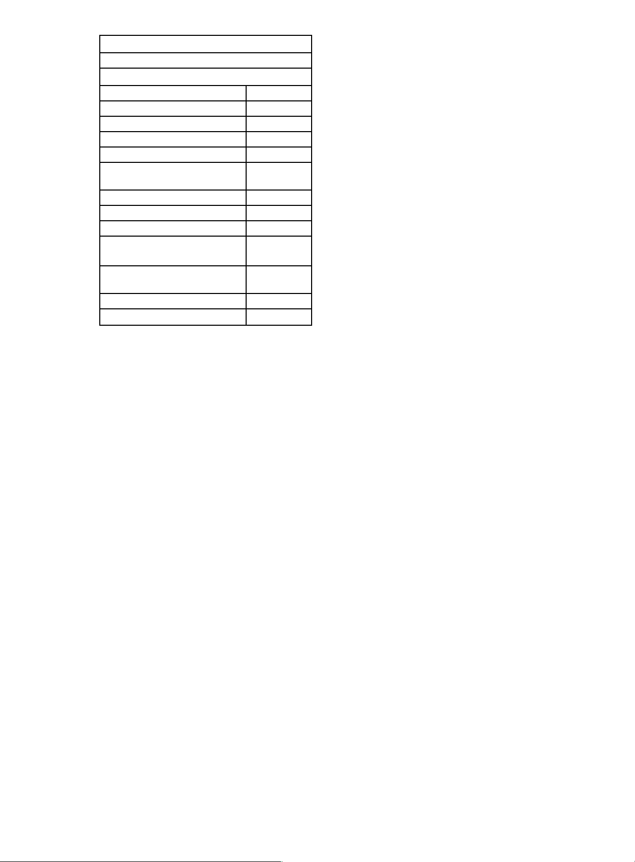
Battery : 11.1V 2800-3 5 00mah lipo 25c
Motor Spes:
Motor: 2223 KV:3400
Technical Datas
KV 3400
Con figu ra tion 9N6P
Stator Diameter 22mm
STator Length 23mm
Shaft Diameter 4mm
Motor Dimension(Dia.﹡Len)
Φ28×40m
m
Weight(g) 118
ldle current(10)@10v(A) 1.5
No.of Cells(Lipo) 3S-4S
Max Continuous
current(A)180S
60A
Max Continuous
Power(W)180S
750W
Max. efficiency current >82%
internal resistance
248mΩ
Recommended Environment: Outdoor
●Caution!
Radio-controlled models, and especially model aircraft, are by no means
playthings in the usual sense of the term. Building and operating them safely
requires a certain level of technical competence and manual skill, together
with discipline and a responsible attitude at the flying field. Errors and
carelessness in building and flying the model can result in serious personal
injury and damage to property. Since we, as manufacturers, have no control
over the construction, maintenance and operation of our products, we are
obliged to take this opportunity to point out these hazards and to emphasise
your personal responsibility.
●Do not fly under the conditions below:
1.Wind strong enough to make the trees rustle.
2.A street with many trees or street lamps.
3.Close to high voltage electrical wires.
4.High Population density areas.
●Cautions for flying
Front lawns and parks make excellent flying areas. Make sure you have permission
to fly and follow safety guidelines set by local authorities. The calmer the wind, the
better!
●Note for Storage
Please disconnect the lipo pac ks when finished flying.
Do not press or crush the airplane when storing.
The best way to store is to hang the airplane to keep the control surface rigid.
Tools:
Scissors, balsa knife, combination pliers, screwdriver. quick-dry glue
•
Page 3
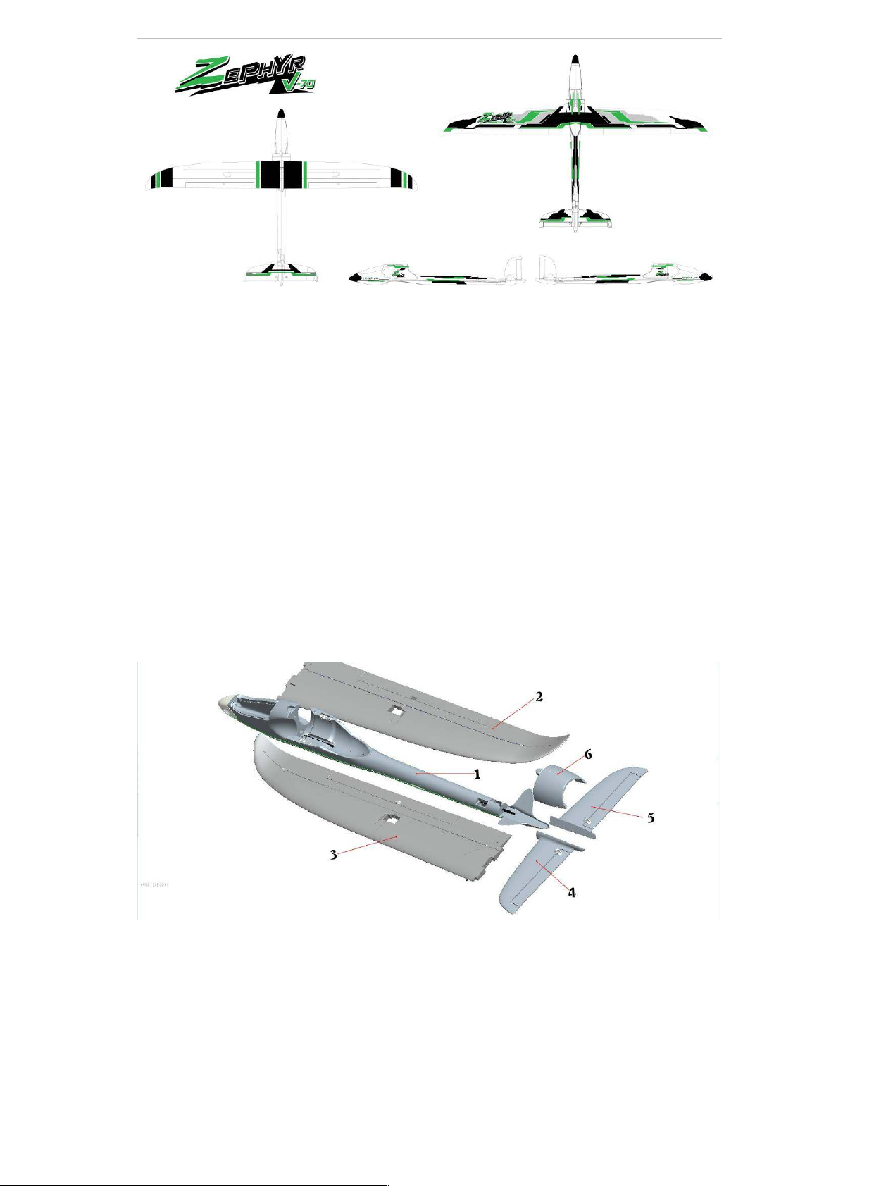
1.Applying the decals
All the adhesive labels and decals are prepared and installed at factory. If it is
not the case, follow the above illustrations applying the labels and/or the
decals to your plane by yourself.
Foam parts included in the packing:
1 Fuselage
2 Left wing
3 Right wing
4 Right Rudder
5 Left Rudder
6 EDF cabin
Parts included in the packing
Page 4
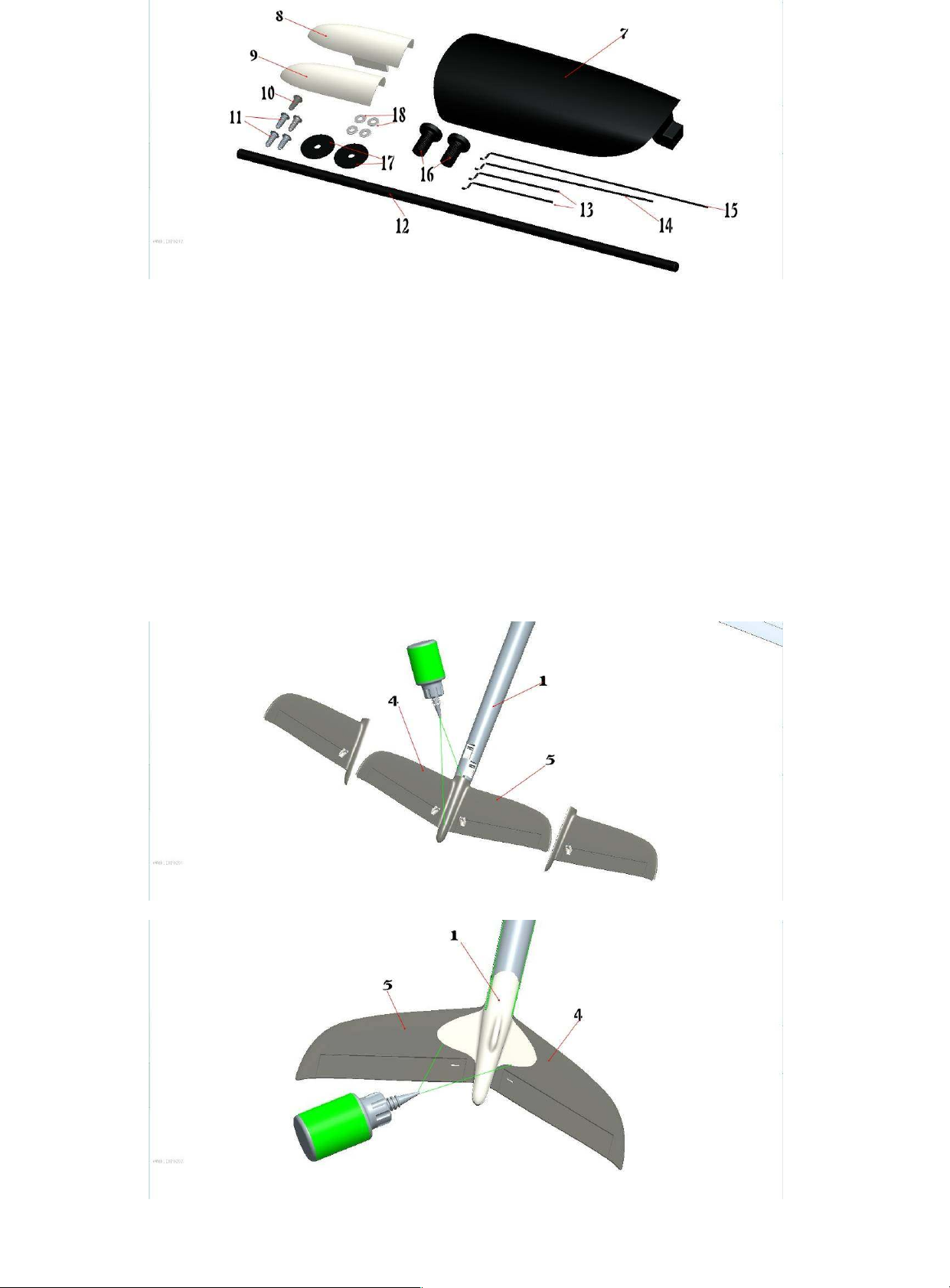
7 Canopy 1pc
8 Right servo arm protector 1pc
9 Left servo arm protector 1pc
10 Screw for EDF cover 1pc
11 Mounting screws for EDF cover 4pcs
12 Glass fiber stick for linking the wing
13 Steel wire for push-and- pull of the wing 2pcs
14 Steel wire for push-and-pull of the spoiler type 1
15 Steel wire for push-and-pull of the spoiler type 2
16 Mounting screws for the wing 2pcs
17 Pads for the wing 2pcs
18 Pads fo the EDF 2pcs
Assembly (Please pay more attention to those which have not been done at
factory.)
1) Stick the tailpieces in place as shown.
2) Glue the back of the rear rudder and the all related plastic parts as
well.
Page 5
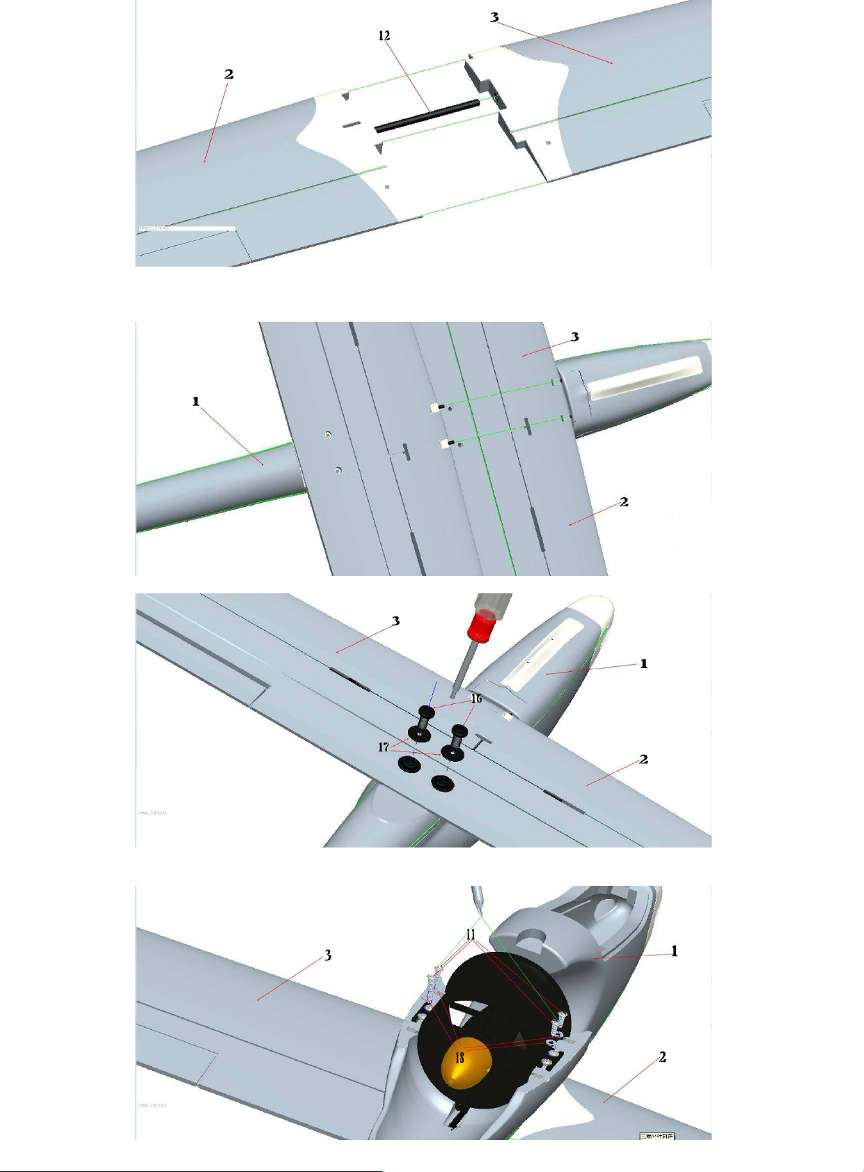
3) Connect right and left wing by using the grass fibre stick as shown in the
picture
4) Aiming at the pin holes, insert the pins.
5) Install the main wing to the bottom of the fuselage by using the mountin
g screws and pads provided.
6) Install the EDF in place onto the fuselage with 4pcs of mounting screws as
Page 6
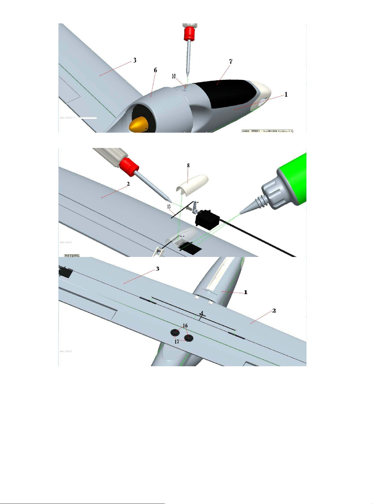
shown in the picture.
Note: Keep all wires in order during installation and never get them installed
reverse.
7) Place the cover of EDF and fasten it with due care by using the mounting
screws.
8) Following the illustrations install the servos seperately to both right and left
aileron , secure with the thrust steel wire , and then stick the cover onto the ar
m.
Note: Tuck the connecting wires of the servos into the slots. Replace with the
longer connecting wires if necessary.
Page 7
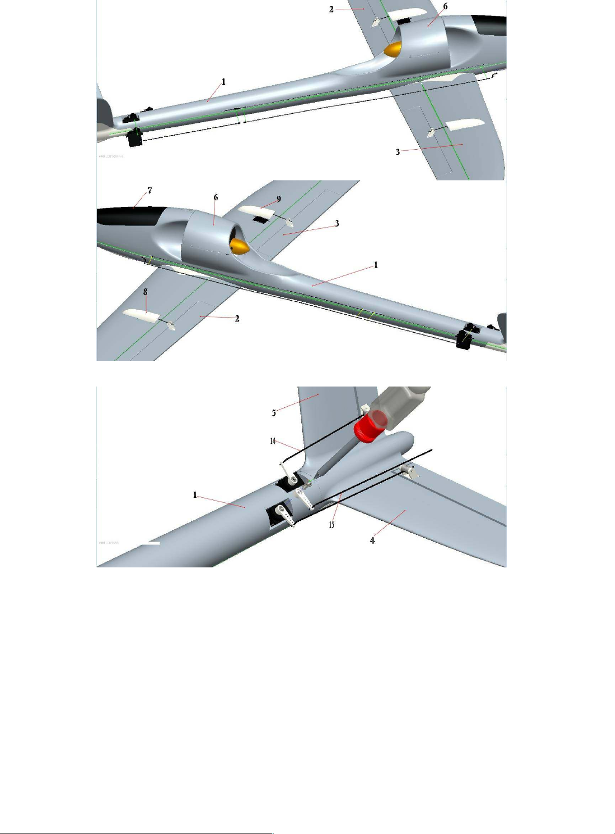
9) Install the rear rudder servo as shown in the picture. ( Replace with the long
er connecting wires if necessary.)
10) Install the servo arm and the thrust steel wire as shown in the picture ,
level up the rear rudder and centre it in place.
Page 8
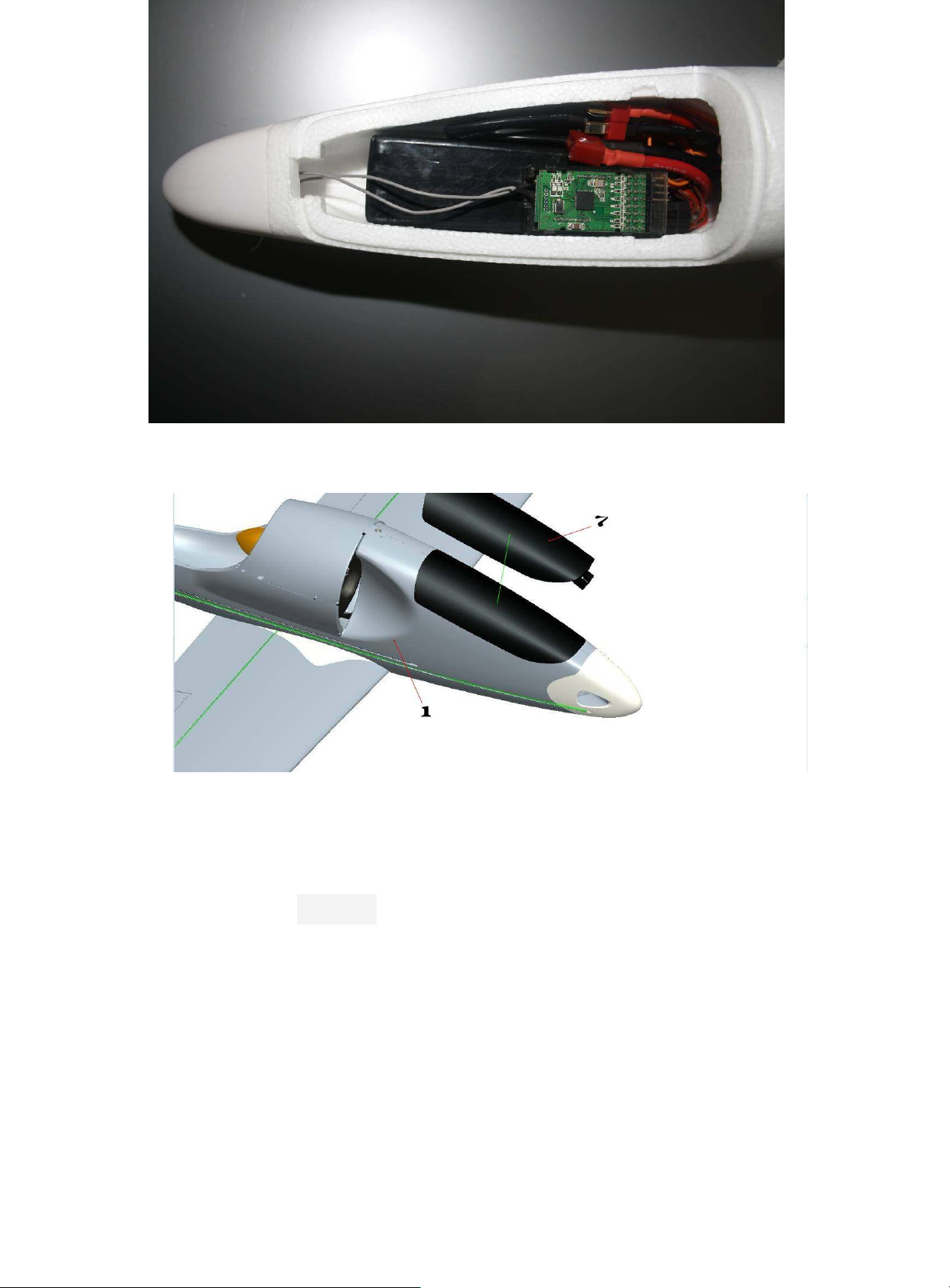
11 Install receiver, ESC and battery, and power on, then debug before
fly.
12 After test, you can cover the equipment cabin canopy as picture shown.
.Recommended Flying Setup
Max servo travel of aileron: 25 degrees up and 25degrees down(20mm)
Max servo travel of elevator:15 degrees up and 15 degrees down(15mm)
Max servo travel of rudder: 15 degrees up and 15degrees down(15mm)
Setting t he correct cont rol surface trav els is important if you wis h t he model to res pond to t he
control commands in a balanced manner.
The t rav els s hould always be meas ured at t he widest part of the control surface.
The c ont rol s urf ace throws are not crit ical , and if y ou are unable to set the exact stated travels
using your transmitter’s adjust ment facilities, that’s no problem. I f the discrepanc y is relatively
great, y ou will need to re-connect the linkage using a different hole at the horn or serv o output arm.
If you intend to fly the model as a trainer, we recommend that you reduce the control surface
travels to about 50 - 60% of the stated values.
Page 9
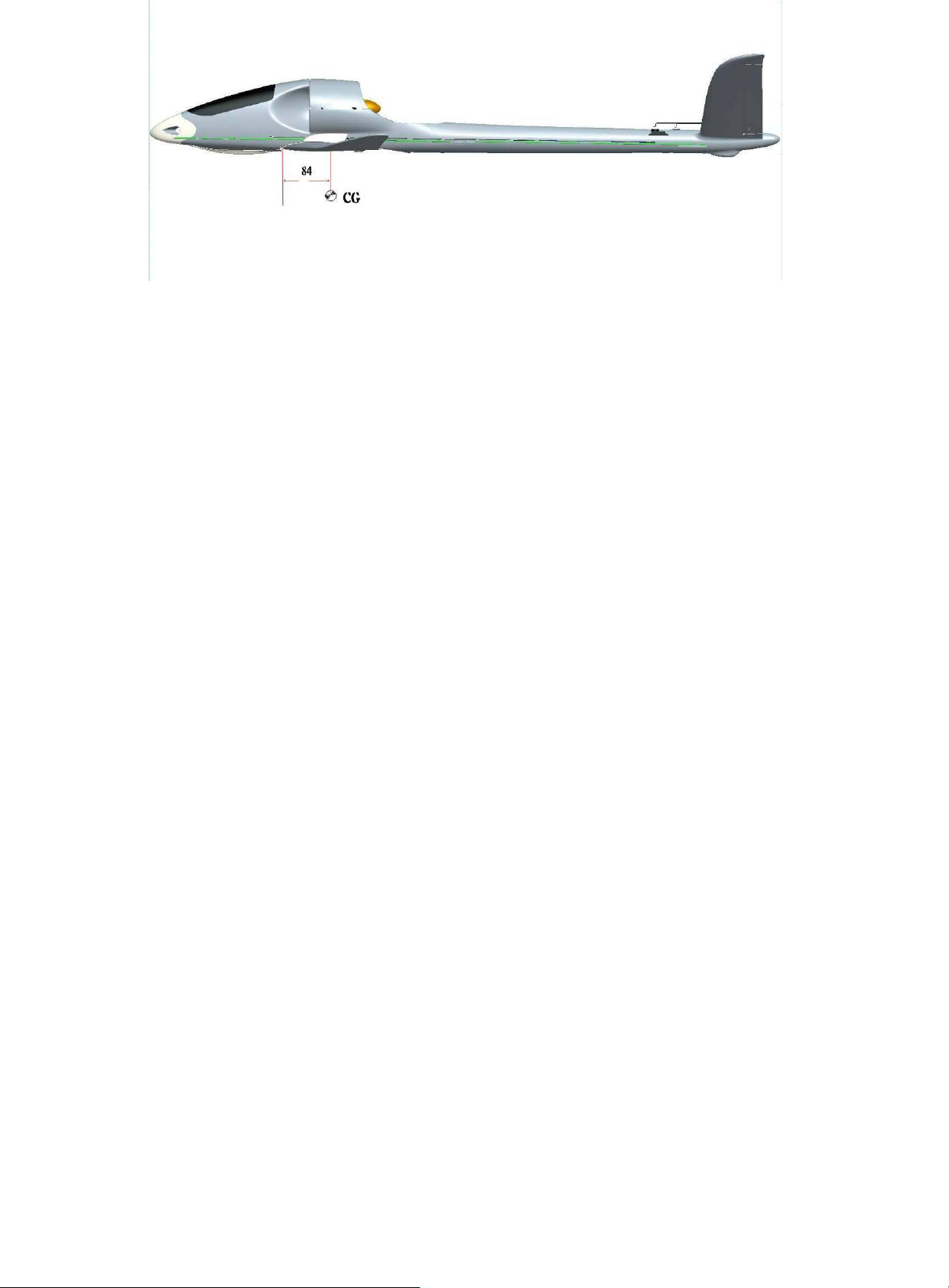
Setting the Centre of Gravity
Like any other aircraft, it must be balanced at a particular point in order to achieve st able flying
characteristics. Assemble your model ready to fly, and ins tall the flight battery.
The Cent re of Gravit y (CG) should be at a position of 84 mm away from wing leading edge, please
refer to att ached picture.
Support the model at this posit ion on two fingertips, and it should balance level. If not, you can
mov e t he f light bat te ry forward or aft to correct the balance point. Once the correct position is
found, mark the location of the flight pack inside the model t o ens ure tha t it is a lwa y s repla c ed in
the same position.
Preparations for the first flight
Please wait f or a day with as little breeze as possible for the mod el’s in itial tes t -fli gh t . The evenin g
hours are of ten ideal for calm conditions.
Be sure to car r y out a r ange check befor e the fir st flight, usi ng the procedur e descri bed in your
RC sy stem instructions. If you encounter a problem, please don’t risk a flight.
The fir st fli ght .. .
If you are a beginner to model flying we strongly recommend.
that you ask an experienced model pilot to help you for the first few flights.
Hand-l aunchi ng
Please don’t try unpowered test-glides with this model – the result is invariably a damaged
airframe. The Ne ptune should be hand-launched with the motor running at half-throttle, and
always pointing directl y into wind.
Ask an exper ience d model ler to hand-launch your aircraft for you.
The launc her shoul d r un f or war d for two or three paces, then gi ve the ma chine a power ful
straight launch, with the wings and fuselage level. Use the controls to hold the model in a
steady, gentle climb - remember to keep the rate of ascent shall ow and the airspeed high!
All ow the aeropl ane to cl imb to a sa fe height, then adj ust the tri ms on the tr ansmitter unti l i t
flies in a perfectly str aight line “hands off”. While the model is still at a safe altitude, throttle
back and try out the c ontrols on the gl i de. Carry out a “dry run” landing approach at a safe
hei ght so that you ar e pr epar ed for t he rea l l anding whe n the batter y r uns fl at.
Don’t tr y any ti ght turns at first , and especi al l y not on the landi ng appr oach at low al titude . It is
always better to land safely at some distance from you, than to force the model back to your
feet and risk a heavy landing.
38 Safety
Safety is the Fir st Commandment when flyi ng any model aircraft.
Thir d par ty i nsurance shoul d be consi dered a basi c essenti al. If you joi n a model cl ub sui tabl e
cover will usually be available through the organisation. It is your personal responsibility to
ensure that your i nsurance is adequate. Make it your job to keep your models and your radio
control system in perfect order at all times. Check the corr ect charging procedure for the
batte r i es you ar e using. Make use of all sensi ble safe ty sy stems a nd prec auti ons w hi ch are
advised for your system. An excellent source of practical accessories is the SUPER-E main
catalogue, as our products are designed and manufactured exclusivel y by practising modellers
for other practising modellers.
Alwa ys fl y wi th a re spons i bl e attitude . You may thi nk that fl ying low over other peopl e’s hea ds
is proof of your piloting skill; others know better. The real expert does not need to prove
hims elf in such childi sh ways. Let other pi lots know that this is what you think too.
Alwa ys fly in such a way tha t you do not endanger yourse l f or other s. Bear in mind that ev en the
best RC system i n the w or l d is subj ect to outside i nter fer ence . No mat ter how ma ny year s of
accident-free flying you have under your belt, you have no idea what will happen in the next
minute.
Page 10

 Loading...