

Page 1
Page 2
□"•
Page 3

CONTENTS:
Introduction
Specifications
Content
Required To Complete Model
Optional Accessories
Assembly (PNF)
Setting Up Your Model
Tundra Options
Floats
FPV Canopy
1
1
2
2
2
3-7
8-10
11
11-12
13
Tow line mounting point
Optional Candy Dropper
Optional Skis
Model Flying Precautions
Pre-flight Checks
Flying The
Tundra Tips
Spare Parts Listing
Trouble Shooting
Contact
Tundra
14
14
15
16
16
17
18
19
20
21
Notes
21-24
Page 4
INTRODUCTION:
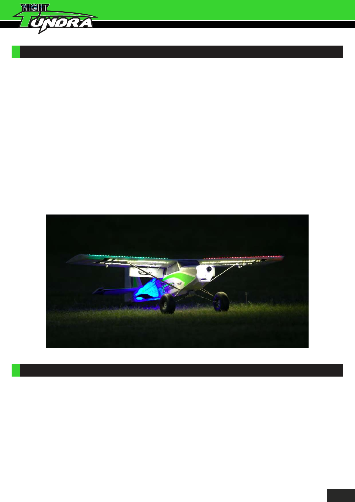
Thank you for purchasing the Durafly Night Tundra, the Night Tundra follows in the footsteps of
the popular Tundra series. No longer do you have to finish flying when the sun sets, with the
incredible light system on the Night Tundra you can just carry on into the twilight and beyond. The
Night Tundra retains the no limits flying characteristics of all the others in the Tundra series.
Whether it’s flying from rough bush fields, water, snow or sand, or FPV, aerobatics, glider towing,
candy dropping or just good old fashioned super STOL slow flying, the Night Tundra takes it all
with ease. Its light weight yet rugged construction, powerful brushless set-up and perfectly
harmonized design gives you instantly a feeling of confidence on the sticks as quickly as it puts a
smile on your face.
Simply put the Night Tundra is an immense amount of fun to fly, and you will be flying very
quickly due to the very straightforward and speedy assembly process. With either the included
floats, tow mounting point and FPV canopy or with optional skis and candy dropper, how you put
your Night Tundra to work, is completely up to you.
Take on the very best mother nature can throw at you either daytime or night time and still come
up smiling. With the Night Tundra, there are literally no limits!
SPECIFICATIONS:
- Wing span: 1300mm(51.7”)
- Length: 920mm (47.2”)
- Flying weight: 1150g (40.6oz)
- Motor: 3636 950kV Brushless outrunner
- Controls: 6-Channels (Throttle, Ailerons, Elevator, Rudder, Flaps, and Lights)
- Battery: 1800-2200mAh 11.1V 3S LiPo(30C min)
- Propeller: Durafly Carbon 12”x6”
- ESC: Aerostar 40Amp Brushless ESC
- Radio system: Minimum 6-channel Rx and Tx required
1
Page 5
CONTENT:
3
9
1
2
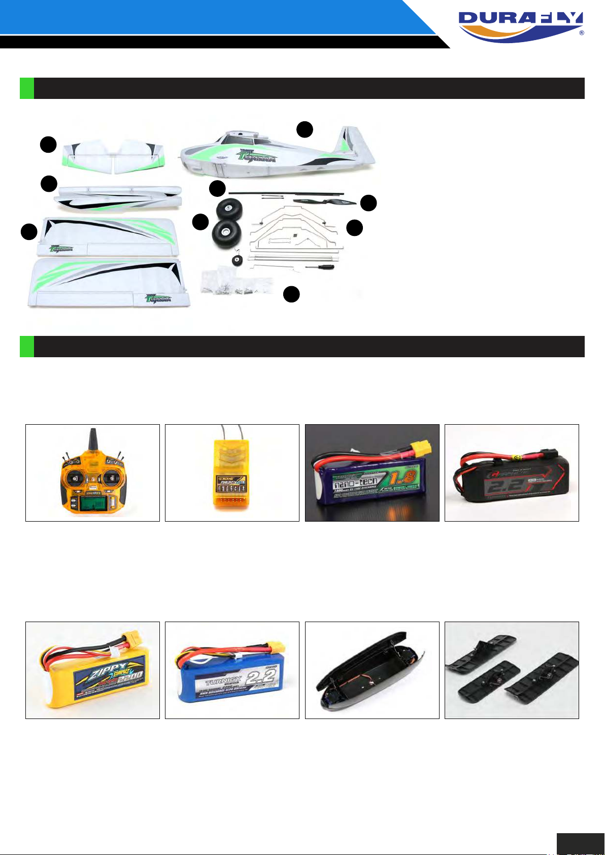
1. Main wing halves
2. Fuselage
6
8
7
5
3. Horizontal stabilizer
4. Control and mounting
accessories
5. Wing, landing gear & float struts
6. Wing and tail spar
7. Main wheels
4
8. Carbon propeller
9. Floats
REQUIRED TO COMPLETE MODEL:
In its ‘Plug n Fly’ format the Night Tundra will still require some additional accessories to get it
‘flight ready’. Durafly recommends the products below for optimum performance and great
value. All are available at Hobbyking.com
OrangeRx Tx6i 6ch 2.4GHz
DSMX Compatible
Int'l Version SKU: 9171001328-0
EU Version SKU: 91710001330-0
OrangeRx R620X V3 6ch
2.4GHz Receiver DSMX
Compatible
SKU: 9171001391-0
Turnigy Nano-Tech 1800mah
3S 65~130C Lipo Pack
SKU: N1800.3S.65
Turnigy Graphene
2200mAh 3S 45C LiPo
Pack W/ XT60
SKU: 9067000134-0
ZIPPY Compact 2200mAh 3s
60c Lipo Pack
SKU: 9067000029-0
Turnigy 2200mAh 3S 40C
LiPo Pack
SKU: T2200.3S.40
OPTIONAL ACCESSORIES
Hobbyking Candy Dropper
Part No. 9499000351-0
Durafly Skymule Ski Set:
Part No. 9310000176-0
2
Page 6
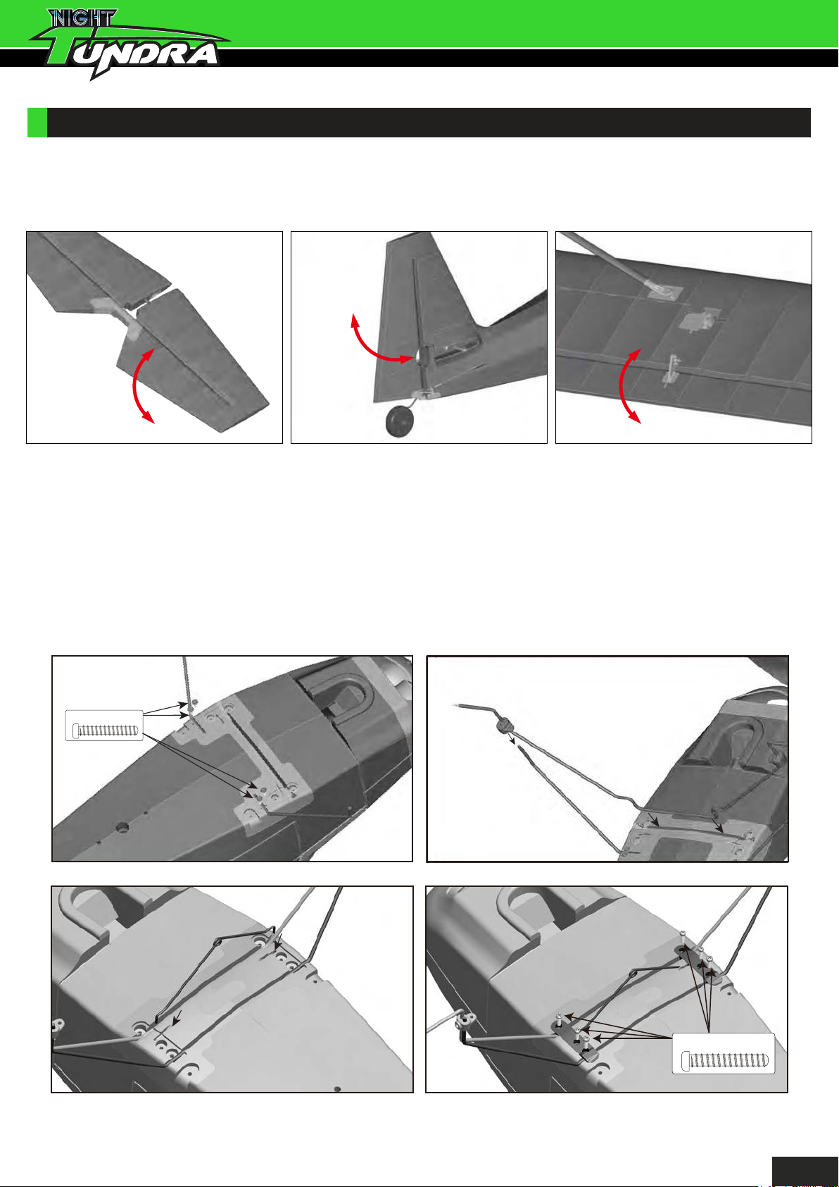
ASSEMBLY (PNF)
1. Out of the box your Night Tundra comes with reinforced foam hinges. However before assembly
can begin, each hinge line must be flexed back and forth 5-6 times to reduce tension and load on the
servo. Do this for all control surfaces before continuing.
2A. To mount the undercarriage to the fuselage, start by inserting and securing the two rear braces
with the supplied M2.5x8mm screws (A). Now insert the main gear wire into the fuselage slot and
slide the plastic brace keepers over the rear braces (B) to bring these two parts together. Insert the
spring support wire between the main gear wire (C) . Using the supplied M2.5x8mm screws
secure the main gear and spring support wire in place with the plastic undercarriage straps (D).
Notes:
- Ensure the main gear rakes forward at stage B.
- Note left (L) and right (R) marked plastic straps and install accordingly during stage D.
A.
M2.5x8mm
C.
B.
D.
M2.5x8mm
3
Page 7
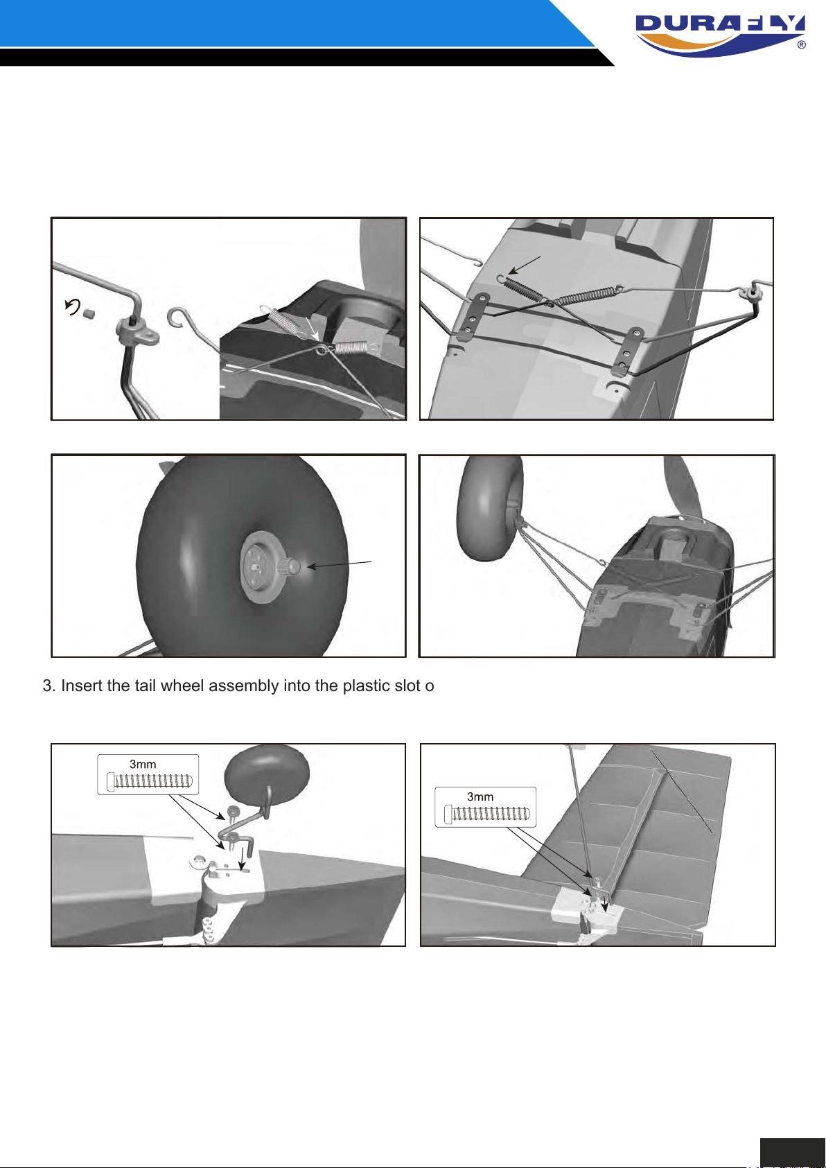
2B. Hook one end of the supplied coil springs through the center ring of the spring support wire (E),
and the wire cross braces through the other end (F). Then hook the wire cross braces through the
plastic brace keeper (E) to complete the sprung cross bracing assembly (F). Now slide the main
wheels onto the axle and secure in place with the plastic grip nut (G). The assembly of the
undercarriage is now complete (H).
E. F.
G. H.
3. Insert the tail wheel assembly into the plastic slot on the bottom of the rudder and secure with
two 3mmx6mm screws (A). The same method is used when mounting the water rudder (B).
A. B.
4. Insert one half of the carbon tail spar into one of the horizontal tail pieces before sliding this half
into the tail slot on the fuselage. Now install the remaining tail piece (A). Secure both halves in
place with the supplied M2.3x6mm screws and the elevator joiner with the single M2x8mm
screw (B). This installation is self aligning, but do double check to ensure equal alignment to the
vertical tail and wing.
x6mm
x6mm
4
Page 8
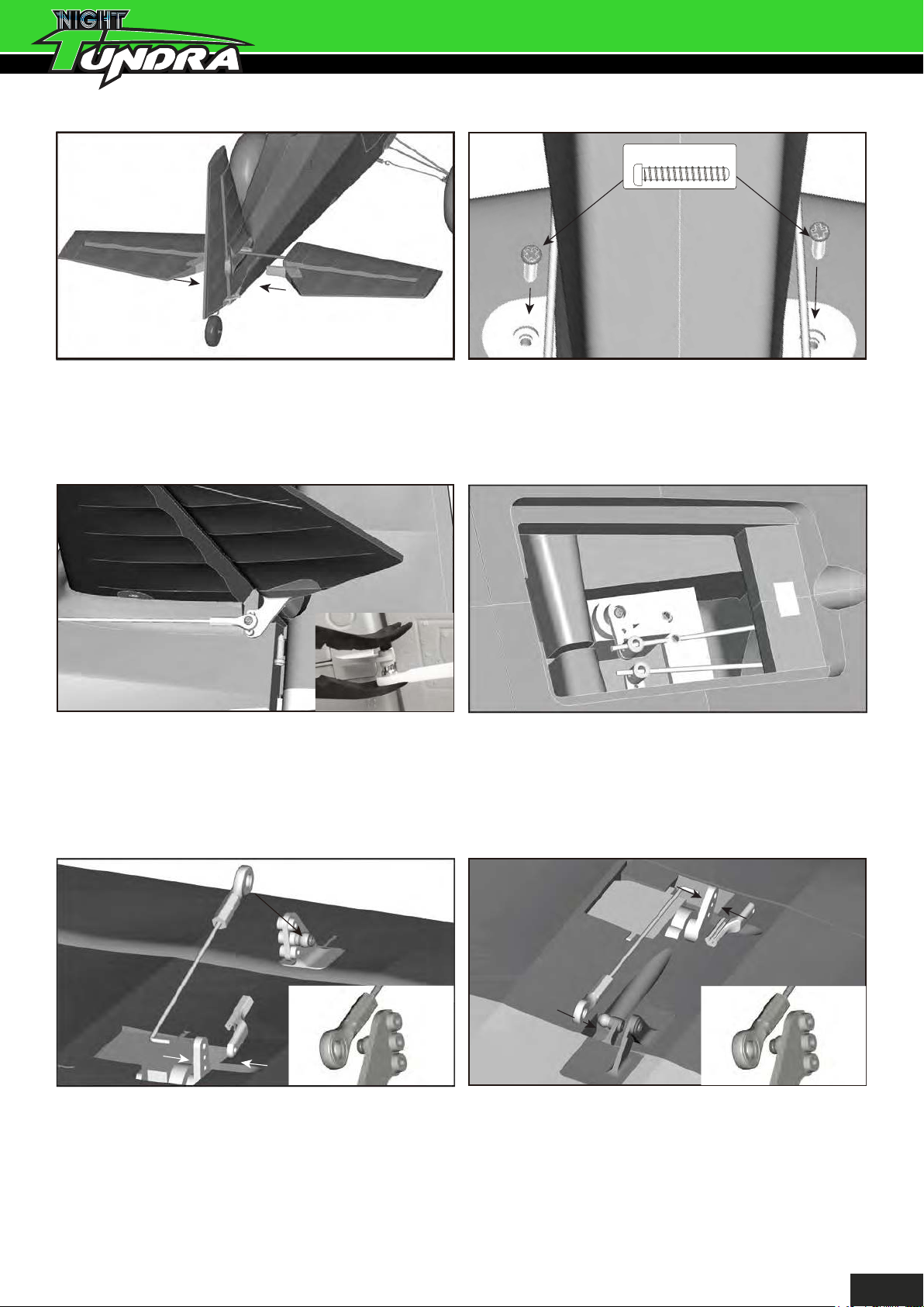
4.
A. B.
5. Using a pair of pliers (ball link pliers preferably) connect the elevator push rod to the elevator horn
(A). To ensure both the elevator and rudder are neutral (with the servos centered) loosen the grub
screw of the piano wire fastener and slide the push rods until both surfaces are neutral if required
(B). Tighten firmly when done. For added security, the tail can be glued in place as well.
2x8mm
A.
6. With the aileron control horns at 90 degrees to the wing surface (neutral) insert the aileron push
rod and secure in place with plastic keepers (A). Connect the ball link to the aileron control horn
as shown (B). Repeat this same process for the flaps, the exception being the flap servo horn
must be positioned as far forwards as possible. This will give a flap neutral position with the
push rod connected (C).
B.
C.
B.
A.
7. Insert the wing spar into the fuselage at the wing root (A) ensuring it is centered. Slide one wing
half at a time onto the spar, pushing each panel firming into place on the fuselage (A) and
secure each panel with the provided M2.5x8mm screws (B). Take care to ensure the wing servo
PCB is not damaged when connecting the wing to the fuselage.
5
Page 9
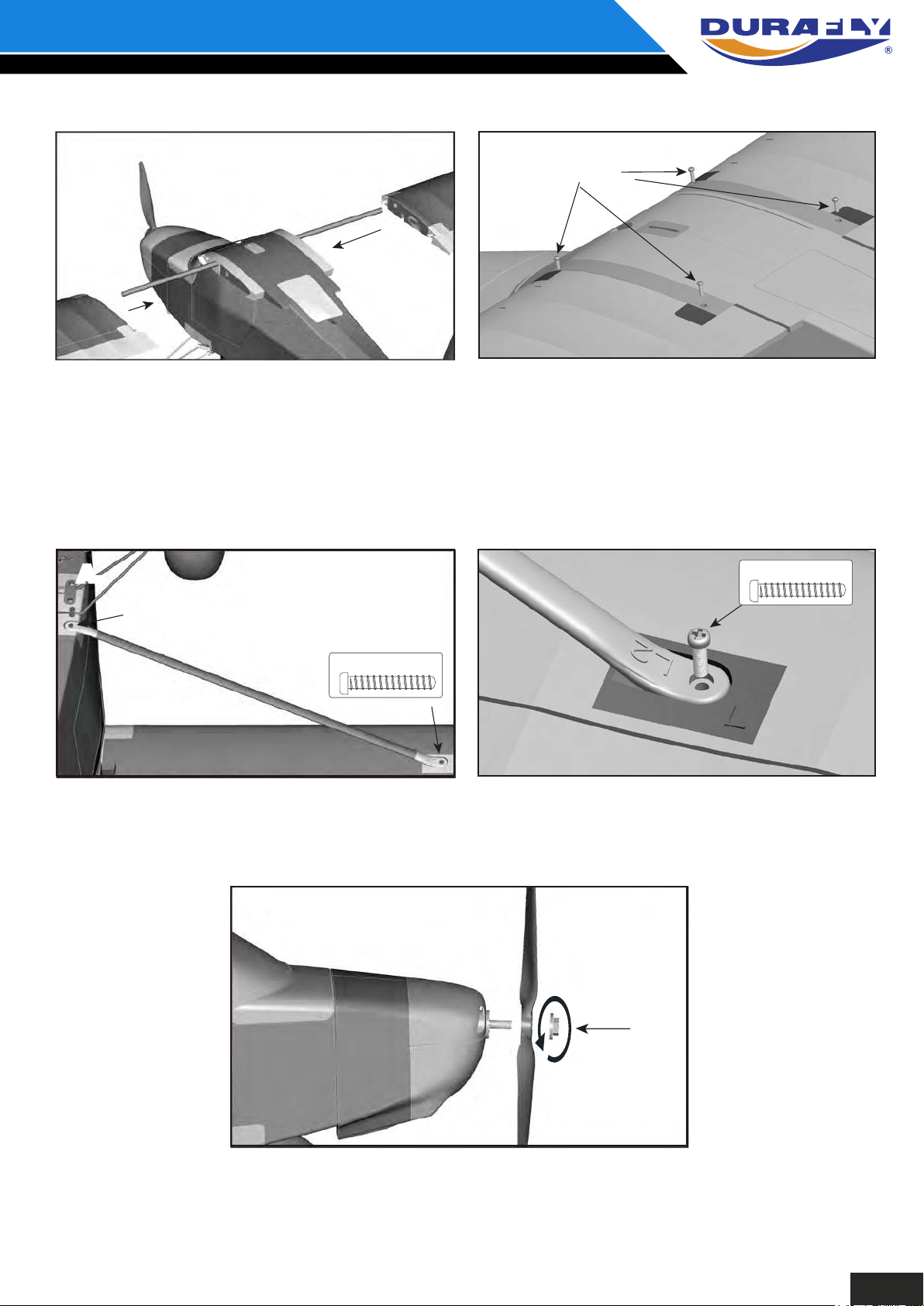
7.
A. B.
Note: For convenience clear tape alone can be used to secure the wing to the fuselage by
running the tape along the entire span of the wing join. However this is not
recommended if you intend to fly the Tundra aggressively.
8. Attach each wing strut to their respective sides (A), both struts are marked ‘L’ and ‘R’ to note left
and right hand sides if looking forward from the cockpit. Secure firmly in place using the
M2.5x8mm screws supplied (B).
M2.5x8mm
A.A.
M2.5x8mm
9. The final stage of assembly is to mount the Durafly 12”x6” carbon propeller using the prop nut as
shown (A). However at this stage it is HIGHLY recommended that all set-up and final checks of
the model be done before finally installing the prop firmly in place.
B.
M2.5x8mm
A.
Note: The propeller should be balanced out of the box, however it is recommended a final
balance check be carried out before attaching to the model. A well balanced prop will
greatly increase all round performance and efficiency of the model in flight.
6
Page 10
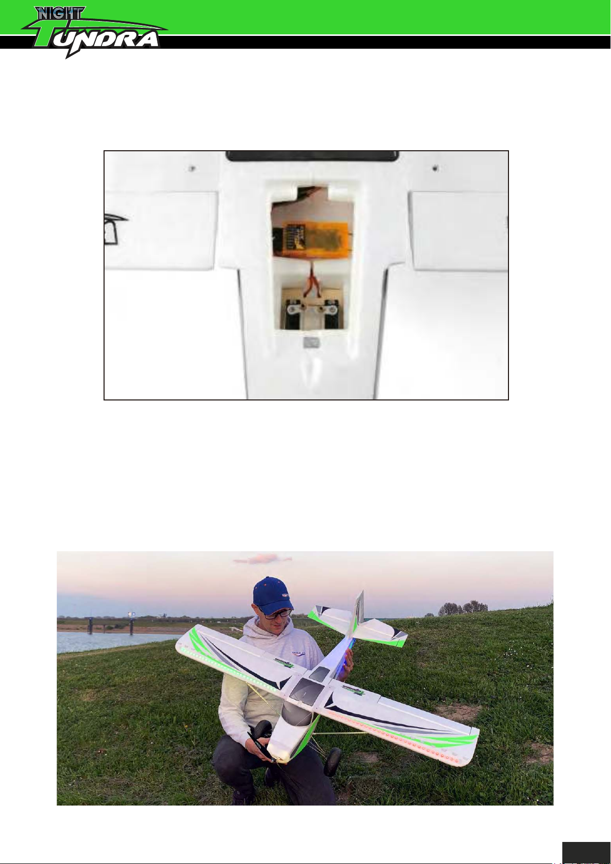
10. Install your choice of 6-channel receiver (OrangeRx R620X shown) using double sided foam
tape or Velcro in the location shown (A) under the rear fuselage access hatch. Ensure Rx aerials
are held away from the servos.
A.
Congratulations, basic assembly of your
Night Tundra is now complete.
Please perform a final check on all screws, bolts and
components, ensuring all are secureand firm in place.
17
Page 11
SETTING UP YOUR MODEL:
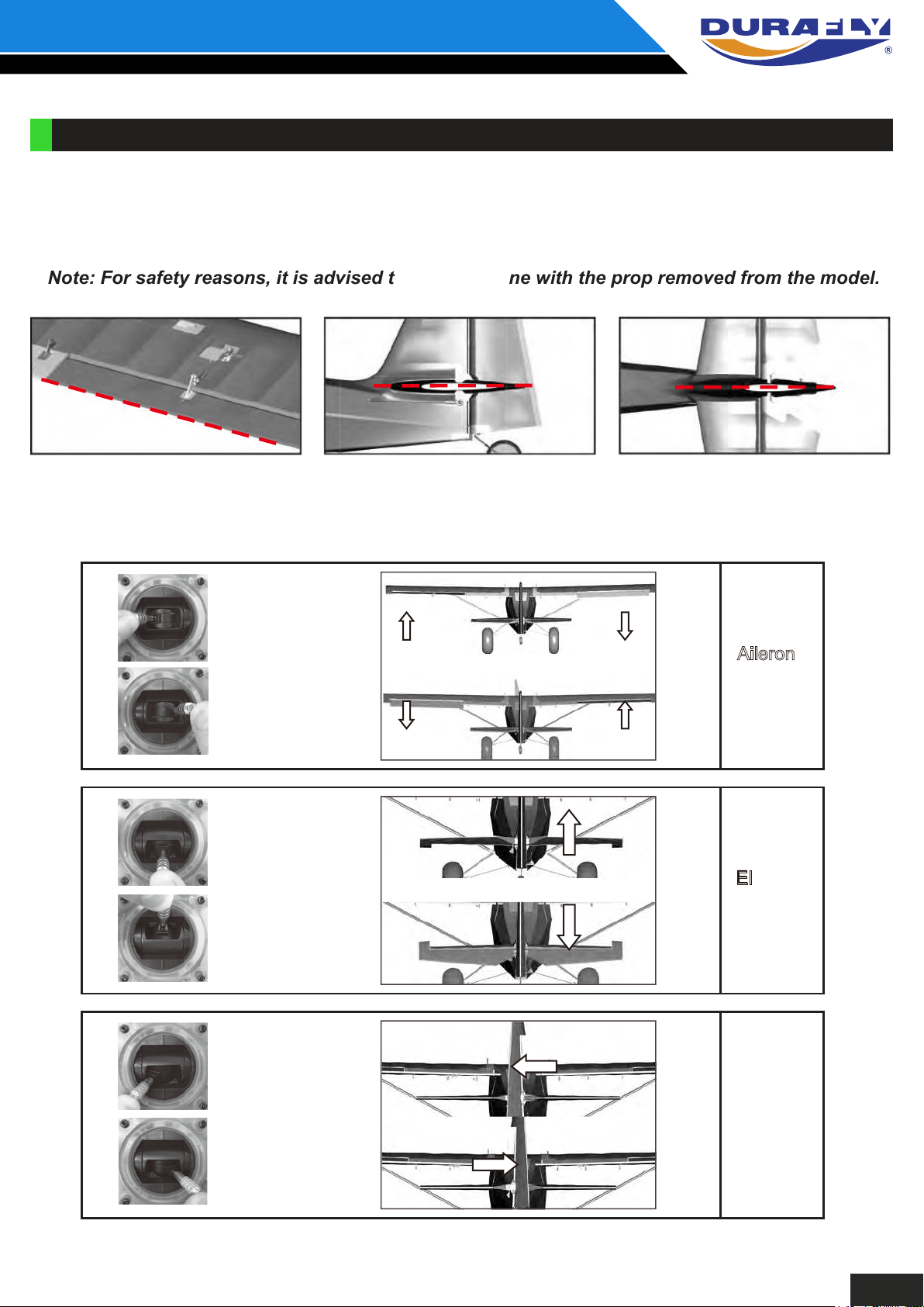
1. With your receiver installed and all servos plugged into their corresponding channels, connect the
flight battery to the ESC to power up the electronics. With the model now armed, ensure all
servos are centered and all control surfaces are level. If not, adjust by screwing the control
clevises by hand, clockwise or anti-clockwise until the control surfaces are level as shown.
Note: For safety reasons, it is advised that this is done with the prop removed from the model.
Aileron Elevator Rudder
2. Check all control surfaces are moving in the correct direction with the correct stick input (see below).
Roll left
Roll right
Pitch up
Pitch down
Yaw left
Aileron
(Roll)
Elevator
(Pitch)
Yaw right
Rudder
(Yaw)
8
Page 12
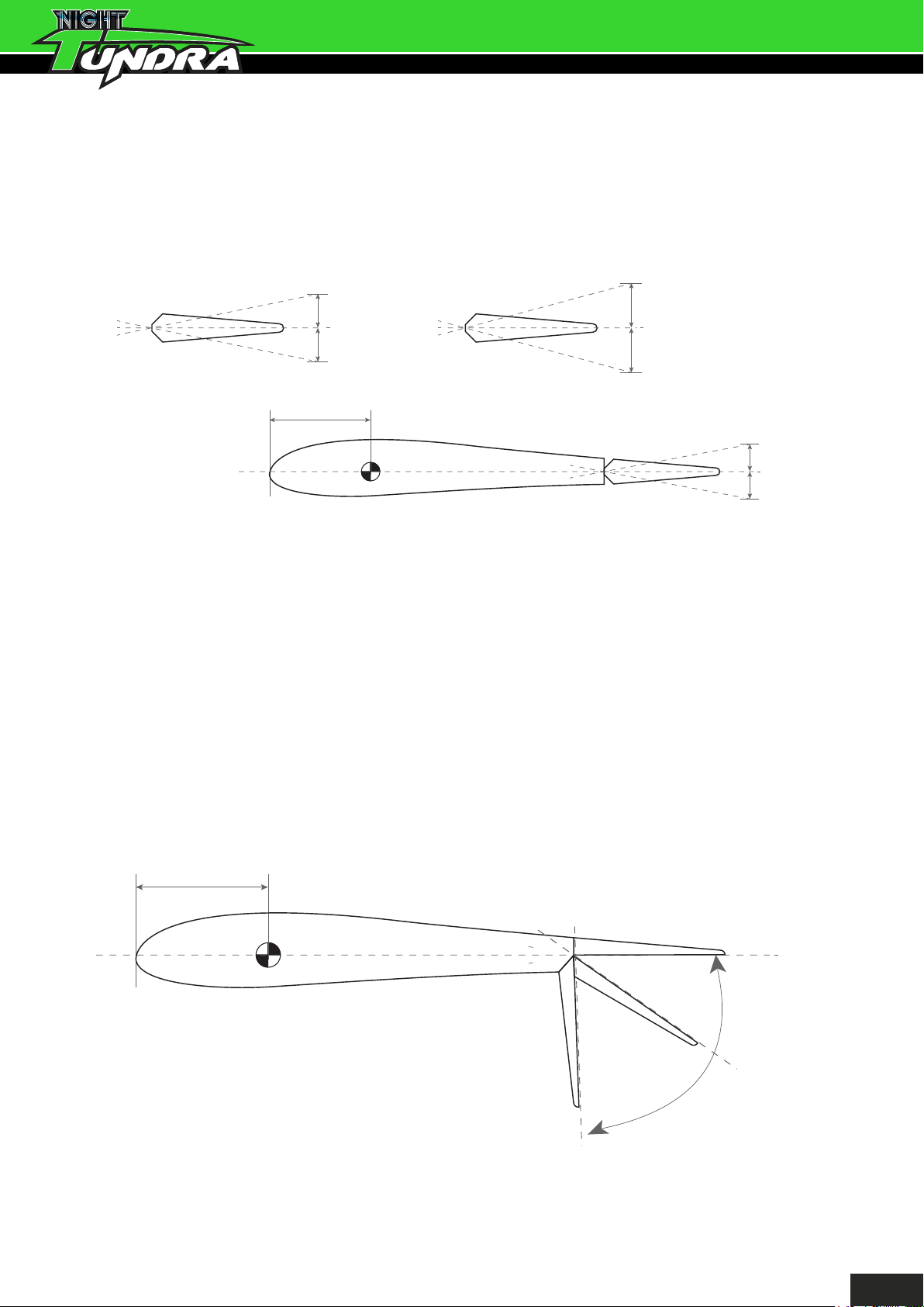
3. The Night Tundra handles very well in flight and that’s not down to good design alone, but a
good pre-flight set-up too. Before you fly your Night Tundra please follow the recommended settings
below for optimum handling and performance.
Control throws:
8-14mm
8-14mm
8-12mm
8-12mm
Elevator
Rudder
50-60mm
Aileron
10-20mm
10-20mm
*Elevator: ‘low rates’ 8mm, ‘high rates’ 14mm in either direction from neutral.
*Rudder: ‘low rates’ 8mm, ‘high rates’ 12mm in either direction from neutral.
*Ailerons: ‘low rates’ 10mm, ‘high rates’ 20mm in either direction from neutral.
4. Flaps on the Night Tundra will need to be set for 3 stages (up/no flap, mid flap and full down flap).
Do this either via your radio or mechanically by turning the clevises on the flap control rod (or
via both in most cases), set mid flap to approximately 45 degrees and full flaps to approximately
90 degrees to the wing. In the ‘up/no flap’ position ensure the flaps close fully without straining
the servos, and are both level with the trailing edge of the neutral ailerons. Also check that both
flaps deploy equally at every stage.
50-60mm
Flaps
45 degrees
90 degrees
9
Page 13
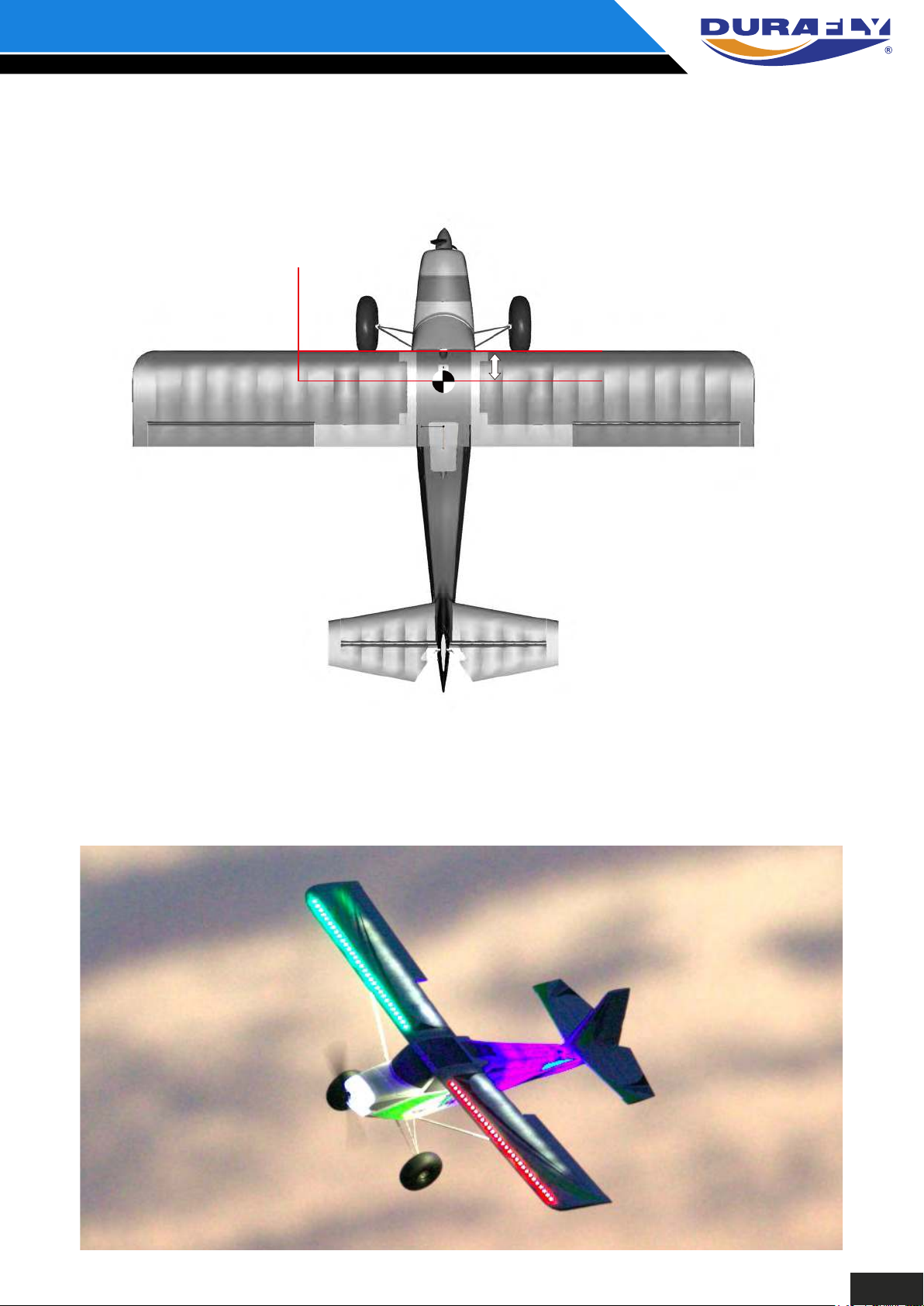
5. The recommended center of the gravity (CG) for the Night Tundra is approximately 50-60mm from
the leading edge of the wing. Your Night Tundra should balance within this range with
anything from a 1800mAh - 2200mAh 3S LiPo installed as far forwards as possible in the
battery area. Your battery can be secured in the battery bay area with the velcro provided.
CG Location:
50-60mm
CG
CG 50-60mm from leading edge.
With assembly and set-up now complete, your Durafly Night
Tundra should now be ready for flight. However we recommend
your read and follow the advice given in the following pages of
this manual before flying your model.
10
Page 14
NIGHT TUNDRA OPTIONS:
YOUR NIGHT TUNDRA COMES WITH SEVERAL FEATURES
Your Night Tundra comes with several features available to you during the assembly. Floats , FPV
canopy and tow mounting point are all included in the box. Use of a Candy dropper and skis are
optional extra’s not included. All however are covered in these following pages.
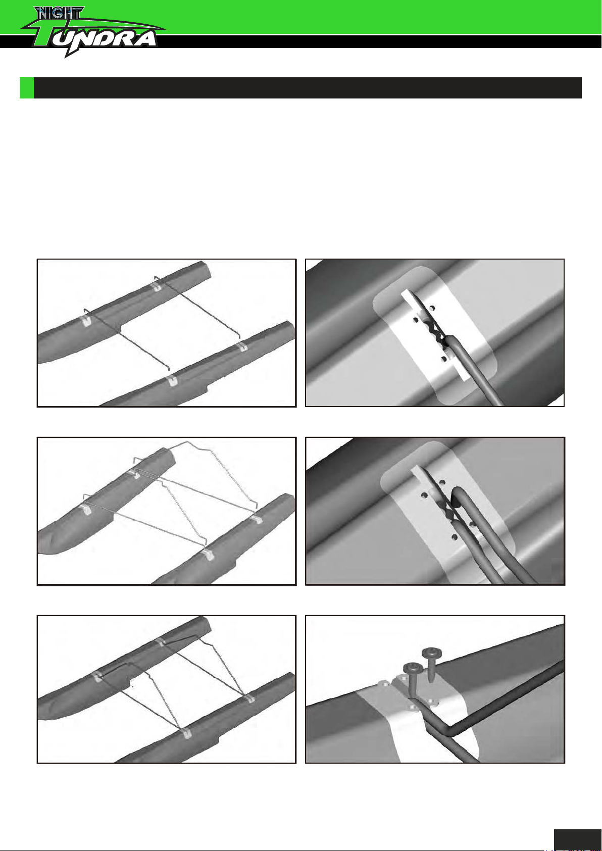
Floats
1. With each float placed on a level surface and parallel to one other, add the front and rear cross
bracing struts by inserting each end into the inner most hole of the float mounting plate (A). Now
insert the ends of the front and rear fuselage mounting struts into the center holes (B). With all
float struts installed as shown, secure in place using the M2x8mm screws (C).
A.
B.
A.
B.
C.
C.
11
Page 15
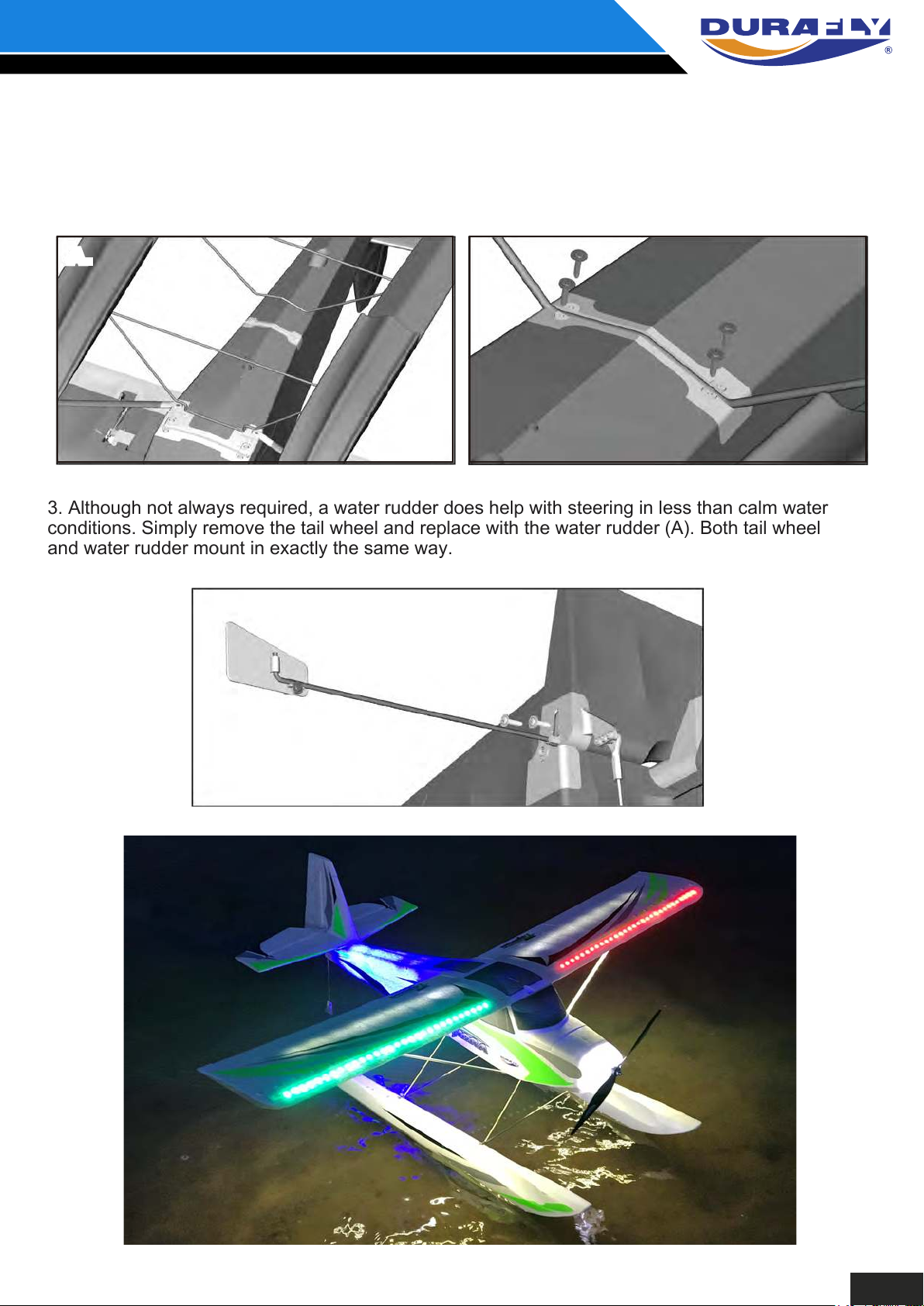
2. With the floats now fully assembled and landing gear completely removed, insert the front
fuselage mounting strut into the main gear housing and onto the rear mounting plate (A). Secure
the rear with supplied M2x8 screws (B) and the front using the original main gear mounting plate
and screws.
A. B.
3. Although not always required, a water rudder does help with steering in less than calm water
conditions. Simply remove the tail wheel and replace with the water rudder (A). Both tail wheel
and water rudder mount in exactly the same way.
A.
12
Page 16
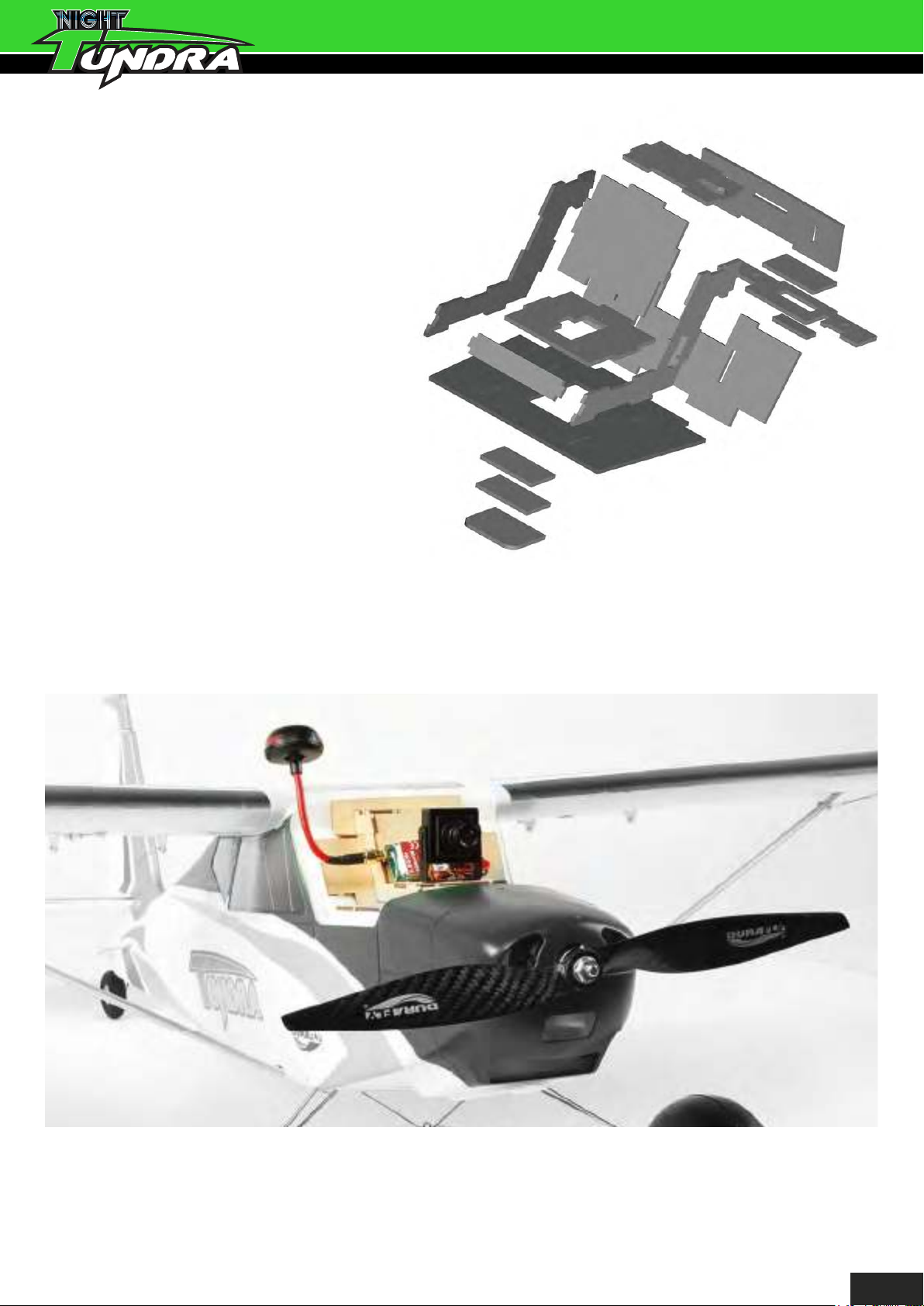
FPV Canopy
To assemble the plywood FPV canopy
you’ll need some CA and no more than
10 minutes to glue it all together. All parts
are laser cut and following the below
exploded diagram, the assembly should
be self-explanatory. Note: Allow some
time for the glue to cure on the magnet
so the bond is as strong as possible. Also
be mindful not to let any glue adhere to
the exposed surface
of the magnet.
With the canopy now assembled you are free to install your FPV equipment as you see fit. However
you may wish to follow the simple example shown below.
13C.14
Page 17
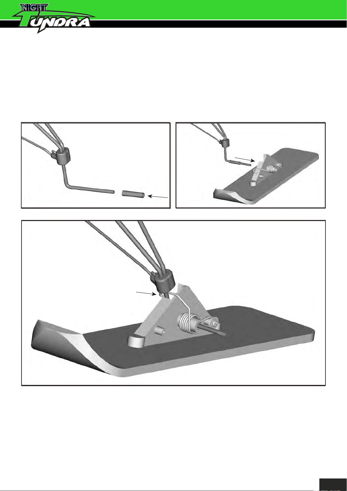
Tow line mounting point
1. With each float placed on a level surface and parallel to one other, add the front and rear cross
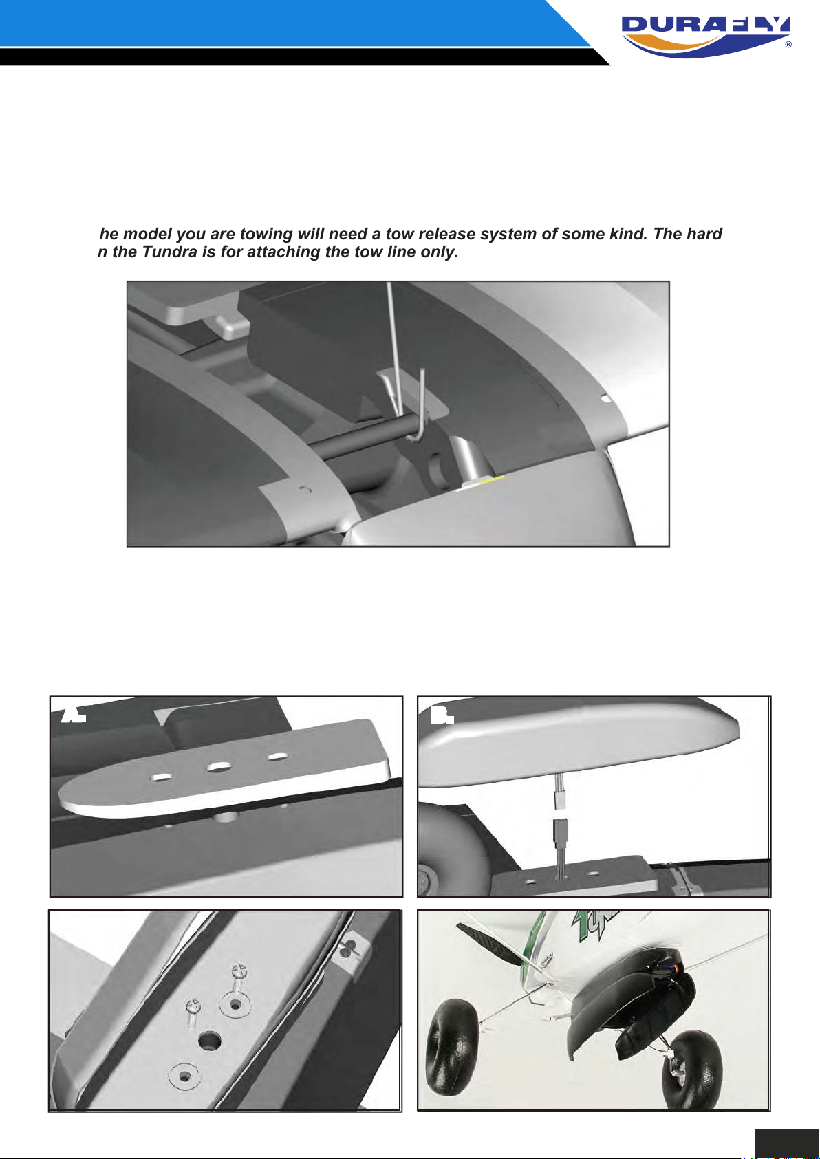
The built-in tow line hard mounting point gives the Night Tundra a solid point close to the CG to
attach a tow line for gliders etc. The below cutaway shows how the tow line should be inserted
and attached to the main spar through the tow line slot.
Note: The model you are towing will need a tow release system of some kind. The hard
point on the Tundra is for attaching the tow line only.
Optional Candy Dropper
Mounting the optional Candy Dropper is quick and easy. Position the foam filler over the mounting
holes on the underside of the fuselage (A). Feed the Y-lead supplied with the dropper through the
center hole and connect to a spare channel on your Rx (B). Secure the dropper using the bolts that
come with it to the fuselage (C).
A.
A.
B.B.
Page 18
Optional Skis
The optional skis are a worth while addition to the Night Tundra for flying from both snow and
soft sand. First remove the main wheels and slide the plastic sleeve over both axles (A). Then
slide each ski onto the axle/sleeve (B) and once in position hook the tension spring around the
back of the landing gear wire (C).
Note: You may wish to add a wheel collet to the axle to give the assembly some additional
security.
A. B.
C.
15
Page 19
MODEL FLYING PRECAUTIONS:
YOUR NIGHT TUNDRA COMES WITH SEVERAL FEATURES
PRE-FLIGHT CHECKS:
Always range check your model before any flight (especially when flying a new model for the first
time). Follow your radio manufacturers guidelines for performing this check.
Check all screw bolts and mounting points are firmly secure, including control horns and
clevises.
Only fly with fully charged batteries (both in your radio and model). Failure to do so could result
in loss of control, damage to the model and/or persons/property around you. Check your
batteries are fully charged.
With the model powered up ( ransmitter on first, then receiver/model) check that all surfaces are
free from damage/obstructions, moving in the correct directions and freely with stick input
Inspect the model and prop for any damage that may have occurred during transit and listen for
any unusual sounds from the electronics when powered up. If in doubt, do not fly.
With the model held securely and the prop free of obstructions, increase the throttle just slightly
to confirm the rotation of the prop is correct. The model should want to pull straight forward with
throttle.
.
If this is your first flight with the model double check the C/G is at the correct position. If not adjust
battery position inside model accordingly.
If you are an inexperienced model pilot seek the help and assistance of an experienced pilot to
perform these final checks and to test fly the model for you.
16
Page 20
FLYING THE NIGHT TUNDRA:
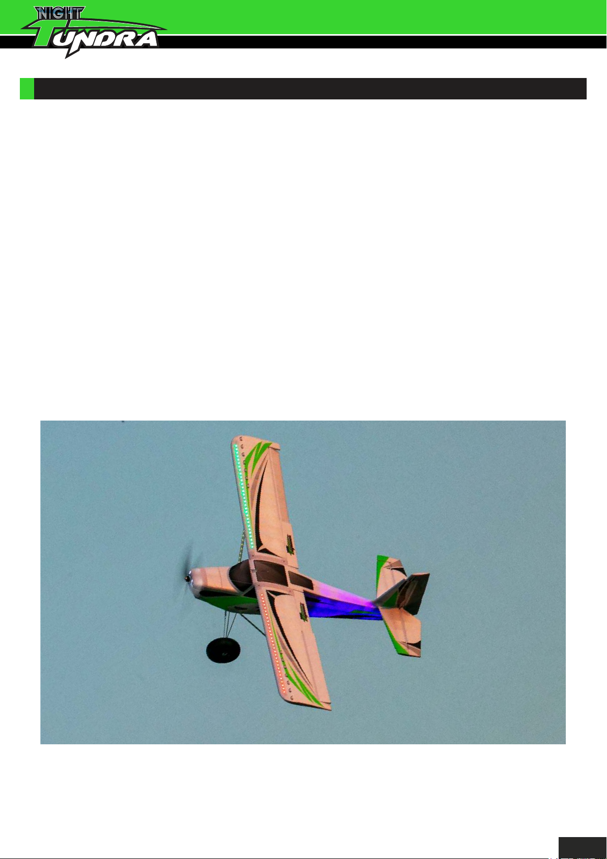
The Durafly Night Tundra is both an easy and versatile aircraft to fly and has no special
considerations when it comes to flying but do make sure you’ve followed the set-up guidelines and
recommendations in this manual thoroughly for the best flying experience.
Thanks to the powerful motor and prop combination you can be off the ground (or water) within just
a matter of meters, or half throttle will give you nice long rolling take-offs, however where’s the fun in
that! Once you have your model trimmed, the real fun starts with the zero roll-out, full flap take offs,
just be ready to hold in some down elevator! In the air the Night Tundra is super stable at any
speeds too, full throttle sport flying allows you to explore the full aerobatic potential of the Night
Tundra, where as at lower speeds and with an indulgent use of the flaps, the Night Tundra really
comes into its own with almost full STOL type flying characteristics, flying slow has never been so
much fun. On the ground too, with the very authentic bush style tires and functional sprung
undercarriage, the ground never looked so inviting. With the Night Tundra rolling across the ground
is just as exhilarating as rolling through the air.
Off water the only real consideration is getting of the surface of the water itself. This is greatly aided
by the use of half flaps on all take off runs as they will help lift the Night Tundra up off the surface of
the water. For towing, just remember to always keep the line tight and to stay below the model
being towed. In the snow or sand with skis, just be mindful that you have less prop clearance, but
maybe you’ll be having too much fun to notice!
17
Page 21
NIGHT TUNDRA TIPS:
If flying from a hard surface (tarmac, as a t, concrete etc) it is recommended that you remove
the spring system from the undercarriage to
When flying with floats of water, it is advised to always use at least half flaps on takeoff. Semi
deployed flaps will greatly increase the
When landing on water, always land with a good amount of forward momentum to help achieve
the smoothest water landings possible.
Use of water rudder should only be needed when flying from rough water. Generally the
standard rudder alone is sufficient for flying off calmer waters.
Due to the added weight of the floats, a 1800mAh 3S would be a more suitable LiPo to use
rather than the heavier 2200mAh 3S when flying from water. This will keep the overall wing
loading
If you intend to perform STOL style landings often with your Tundra, it is suggested you use the
optional tail brace upgrade supplied with most models. This will greatly improve the strength
and rigidity of the tail which will be of great benefit with the higher forces at play with landing
.
void excessive bouncing on landings.
Tundra's ability to lift off the water surface.
STOL.
For optimum flight performance/model longevity, it is highly recommended that you always fly
with a balanced prop. The supplied prop should be balanced, but it’s always good to check first.
Keep all leads within the fuselage area as tidy as possible. Tidy wires look better, allow for
easier access to all internal components, better battery installation, increased airflow around
electronics and a reduction in potential electronic signal interference (noise).
Do not leave your model in direct sunlight for prolonged periods of time
. This will have an adverse effect on the foam surface of the model.
Thank you again for purchasing the Durafly Tundra,
we know you’ll enjoy it immensely.
Don’t forget, spare parts are available for this model, please see
opposite for details.
18
Page 22
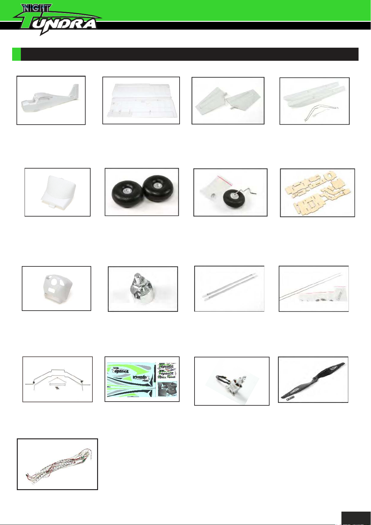
SPARE PARTS LISTING:
Fuselage Set
SKU: 9499000422-0
Canopy/Battery Hatch
w/Magnet
SKU: 9499000426-0
Main Wing Set w/Hinges & Horns
SKU: 9499000423-0
Main wheels
SKU: 9499000067-0
Horizontal Tail Set
SKU: 9499000064-0
Tail wheel Set
SKU: 9499000068-0
Float Set
SKU: 9499000065-0
FPV Tray
SKU: 9499000069-0
Nose Cowl
SKU: 9499000424-0
Main Landing Gear Assembly
SKU: 9499000384-0
LED Light Set
Prop Adapter
SKU: 9499000071-0
Decal Set
SKU: 9499000425-0
Wing Struts
SKU: 9499000072-0
3636-950KV Motor w/
Motor & Prop Adaptor
SKU: 9499000076-0
Hardware
SKU: 9499000073-0
12x6 Carbon Prop
SKU: 9499000077-0
SKU: 9499000427-0
19
Page 23
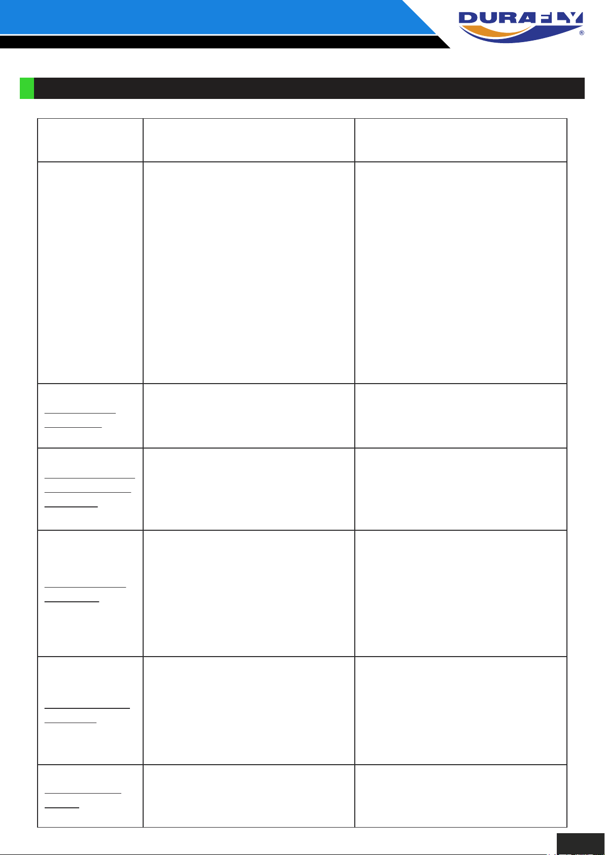
TROUBLE SHOOTING:
Problem Cause Solution
Motor does
not turn
Model moves
backwards
Control surfaces
not moving with
stick input
1. Batteries is not fully charged.
2. Transmitter battery low.
3. Motor not connected.
4. The motor is damaged.
5. Receiver is not bound to Tx.
6. ESC in set-up mode.
1. Prop installed backwards 1. Swap the prop around.
1. The servo lead is connected
to Rx incorrectly.
2. The servo is damaged.
1. Charge the batteries.
2. Install a charged battery.
3. Check for connection
between the ESC and motor.
4. Replace motor.
5. Consult Radio manual and
go through bind procedure
again.
6. Hold model and move
throttle to full position then
back down to idle.
1. Make sure the servo leads
are connected properly.
2. Replace servo.
Model does not
fly straight
Model does not
climb well
Limited Radio
Range
1. Control surfaces not centered.
CoG is not in the correct position.
2.
1. The battery is not fully charged.
2. Elevator servo is reversed.
3. CG too far backwards.
1. Transmitter/Receiver batteries
are flat.
1. Adjust the trims on the
transmitter.
2. Re-position LiPo as
suggested.
1. Charge the battery.
2. Change servo direction via Tx.
3. Move battery forwards.
1. Charge/replace batteries.
20
Page 24
Contact:
Notes:
21
Page 25

Notes:
22
Page 26

Notes:
23
Page 27

Notes:
24
Page 28

UK REP
EC REP
APEX CE SPECIALISTS LIMITED
M1 4HT, UK
APEX CE SPECIALISTS LIMITED
 Loading...