

Page 1

GLOSTER GLADIATOR MK1
DURAFLY 1100MM PLUG AND FLY
Page 2
Page 3
CONTENTS
12-17
18
19
19
20
21
22
23
24
24
Page 4

GLOSTER GLADIATOR MK1
DURAFLY 1100MM PLUG AND FLY
INTRODUCTION:
The Gloster Gladiator was a British built biplane fighter, it was used by the Royal Air Force and
Fleet Air Arm during the late 1930's. It was the RAF's last, and ultimate biplane fighter airplane
to be manufactured, but it was also the first to feature an enclosed cockpit.
The Durafly version of this iconic biplane is a replica of the Shuttleworth Collections Gloster
Gladiator Mk1 "K9785", believed to be the only airworthy example flying in the world today.
"K9785" depicts the markings of No. 73 Squadron, that operated Gloster Gladiators at RAF
Mildenhall in England from 1937 to 1938.
The Durafly Gloster Gladiator is manufactured in strong EPO foam, to the usual high standards
you have come to expect from this range of RC airplanes. As all other Durafly models, it comes
"Plug N Fly", this means it is supplied with an easy to assemble airframe, installed motor and
ESC, and pre-installed servos. The attention to detail is superb from the blistered cowl, scale
exhausts, and scale streamlined landing gear with scale wheels. The ribbed wings, tail, and
stringered fuselage depicts a fabric covered airframe, and blistered machine gun housings make
this a model you will be proud to own.
SPECIFICATION:
Wingspan:1100mm (43.3”)
Length: 938mm (36.9”)
Flying weight: 1600g (56.4 oz)
Motor: 3719-770KV brushless outrunner.
Battery: 2200mah 4S 30C or more recommended (not supplied)
Channels: 4-6 channel required.
ESC: Aerostar 40amp w/BEC
Servos: 4 x 9g digital
Prop: 2 blade 11x7
1
Page 5
CONTENTS:
1. Fuselage
2. Main Wings
3. Decal Sheet
4. Horizontal Stabilizer
5. Scale Detailing Parts
REQUIRED TO COMPLETE MODEL:
6. Scale Spinner w/Prop Adapter
7. Scale Landing Gear.
8. Large Diameter Scale Wheels.
9. Complete Accessory Pack Including 11x7 Prop,
Linkages, Y Lead, and Tool Kit
2
Page 6

GLOSTER GLADIATOR MK1
DURAFLY 1100MM PLUG AND FLY
ASSEMBLY of the Gloster Gladiator (PNF):
Note: If using the supplied stick on decals, we suggest you add these before building the model,
you may find it a bit easier. For advice on applying the decals, please go to pages 10-12 of this
manual.
1. Out of the box your Gladiator comes with reinforced foam hinges. However before assembly
each hinge line must be flexed back and forth 5-6 times to reduce tension and load on the servo.
Do this for all control surfaces before continuing. If you wish for extra security you can add some
hinge tape top and bottom to reinforce the hinge line.
3
Page 7
2. Remove one of the wheel collars from an
axle. Remove the inner wheel hub from one of
the wheels and slide it onto one of the axles
as shown. Then slide the wheel collar back on
to the axle.
3. Tighten the grub screw using the hex-key
supplied, ensure the grub screw tightens
onto the flat of the axle. A drop of thread
locker can be used if you wish for extra security.
4. Remove the outer hub from the wheel, then
slide the wheel back over the inner hub. Re-fit
the outer hub and carefully line up the screw
fixing holes.
6. Out of the box, the cowling and dummy
engine are just pushed on, they are not
secured in place. For the next steps you will
need to remove these from the fuselage.
5. Using the supplied 2.3mm x 10mm self-
tapping screws, secure the inner and outer
hubs together. Do not over-tighten or you will
strip the plastic out of the screw spigots.
7. Slot the landing gear into the groove in the
bottom of the fuselage, ensure the landing gear
fairings are facing the correct direction. Look at
the aerofoil shape.
4
Page 8
GLOSTER GLADIATOR MK1
DURAFLY 1100MM PLUG AND FLY
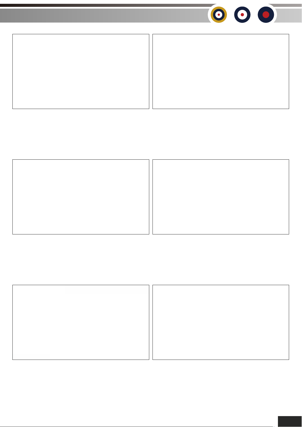
8. Use the supplied 2.3mm x 10mm hex
screws with the molded on washer to secure
the landing gear retaining straps in place.
10. Use a good contact adhesive to glue the
dummy exhausts into place. These slide in
from the side slightly so that the box section at
the front of the exhausts locate into the slots
into the fuselage.
9. Also use 2.3mm x 10mm hex self-tapping
screws to retain the landing gear fairings to the
sides of the fuselage.
11. Once again using a contact adhesive, glue
the air-scoop into place in the cross grooves
between the exhausts.
12. Replace the cowl and dummy engine and
secure in place using 2 of the supplied 2.3mm
x10mm self-tapping screws. Note: If the flange
on the inside of the cowl slightly fouls the front
of the dummy exhausts, then please trim a
piece of the flange off with cutters to allow for
the cowl to obtain a more snug fit.
13. The horizontal stabilizer and elevator come
pushed together in the box, pull these apart
and slide them through the rear of the fuselage
as shown. They are a good tight fit, so ensure
they are fully pushed home and the screw
holes line up.
5
Page 9
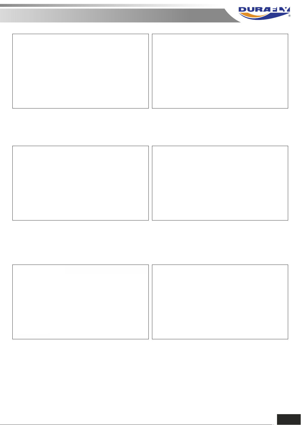
14. Connect the elevator halves using the
supplied 2.3mm x 6mm self-tapping screw.
15. Secure the horizontal stabilizer halves to
the fuselage using the supplied 2 off 2.3mm x
6mm self-tapping screws.
16. Connect the pushrod ball-link to the
elevator control horn. You may need to
clean some silver paint off of the ball
first.
18. Select the 2 short aileron pushrods and feed
the end with the 90° bend through the outer
holes in the servo arms, secure with the
supplied quick-keepers. Center the servos once
more, set the aileron at neutral and adjust the
ball-link as necessary. If this is a tight fit then
there may be some silver paint on the ball.
17. Center the elevator servo with either your
radio or a servo tester. Hold the elevator in the
neutral position and then tighten the
grub-screw on the servo connector.
19. Slot the bottom wing onto the fuselage wing
seat, ensure the aileron leads feed through the
hole into the radio compartment and are not
trapped beneath the wing. If you are using the
supplied "Y" lead, then it is best to connect this
now. If you are going to use separate aileron
channels then it is also best to fit your
extension leads at this point.
6
Page 10
GLOSTER GLADIATOR MK1
DURAFLY 1100MM PLUG AND FLY
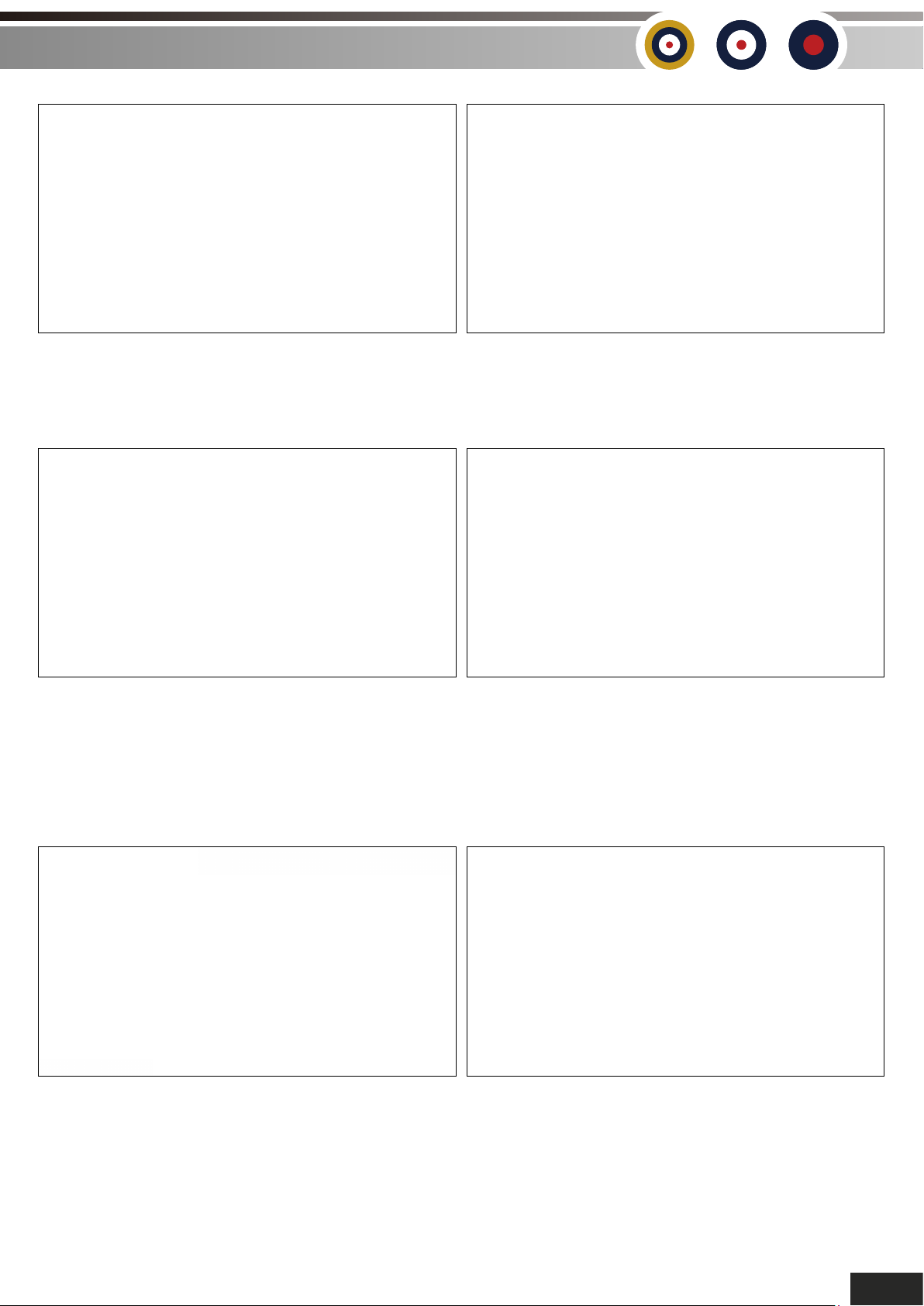
20. Secure the bottom wing to the fuselage
using the 4 supplied M3 x 20mm machine
screws.
22. Carefully identify which strut goes where
and which way around. The brackets for the
flying wires go towards the top wing, and the
top fixing hole that is countersunk goes to the
front. Secure the cabane with 2 off 2.3mm x
8mm hex screws with molded on washers.
21. The next step is to attach one of the
cabane struts to the fuselage.
23. The interplane struts can now be added.
Once again, very carefully identify which is
which. They need to rake forwards when
placed in the bottom wing, and the aerofoil
shape needs to face the correct way, into the
airflow.
24. The interplane struts push into the wings,
and the special fasteners that are factory
installed hold them in place. Push them in until
you hear a click, they are then secure. If you
need to remove them then carefully push the
locking tab away and pull out the strut.
25. Attach the second cabane strut, once
again use the supplied 2.3mm x 8mm hex
screws with the molded on washers.
7
Page 11
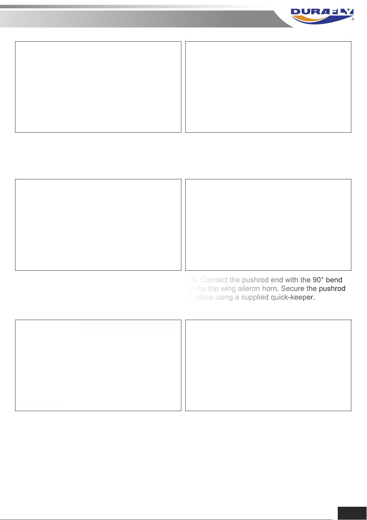
26. Next step is to attach the top wing. It is best
to start with one set of interplane struts and
firmly locate them, then locate the other side.
27. With the interplane struts firmly located, line
up the cabane struts to the top wing fixings.
Secure once again with the 2.3mm x 8mm hex
screws with the molded on washers.
28. Use the long pushrods to connect the top
and bottom ailerons. It is best to have the
aileron servos connected to your radio or a
servo tester and set the servos at neutral.
30. Adjust the length of the pushrod by screwing
the ball-link clockwise or anti-clockwise until it
perfectly aligns with the ball on the bottom wing
aileron. Ensure the bottom aileron is still set at
neutral, snap the ball-link into place. Repeat for
the other wing. Once again, clean off any silver
paint that may be on the ball.
29. Connect the pushrod end with the 90° bend
to the top wing aileron horn. Secure the pushrod
in place using a supplied quick-keeper.
31. Slide the spinner backplate onto the motor
shaft and locate it onto the hex driver. Next fit
the propeller, then the heavy prop nut, tighten
with a tommy-bar or similar. Then fit the
spinner cone, ensure this locates correctly into
the backplate, secure using the supplied M3 x
25mm machine screw. Note: Do not fit the prop
if you haven't yet set up your radio and the
ESC, ensure you do this before fitting the prop.
8
Page 12
GLOSTER GLADIATOR MK1
DURAFLY 1100MM PLUG AND FLY
32. Do a final check that everything is square,
and that both wings line up with each other.
34. Do the same with the elevator to ensure it
is neutral.
33. Double check that when your aileron stick
and the trim is at neutral that all the ailerons are
at neutral.
35. Do the same with the rudder to ensure it is
neutral.
36. Using a contact adhesive, glue the 2
fuselage machine guns into place as shown.
37. Using a contact adhesive, glue the 2 wing
machine guns into place as shown.
9
Page 13
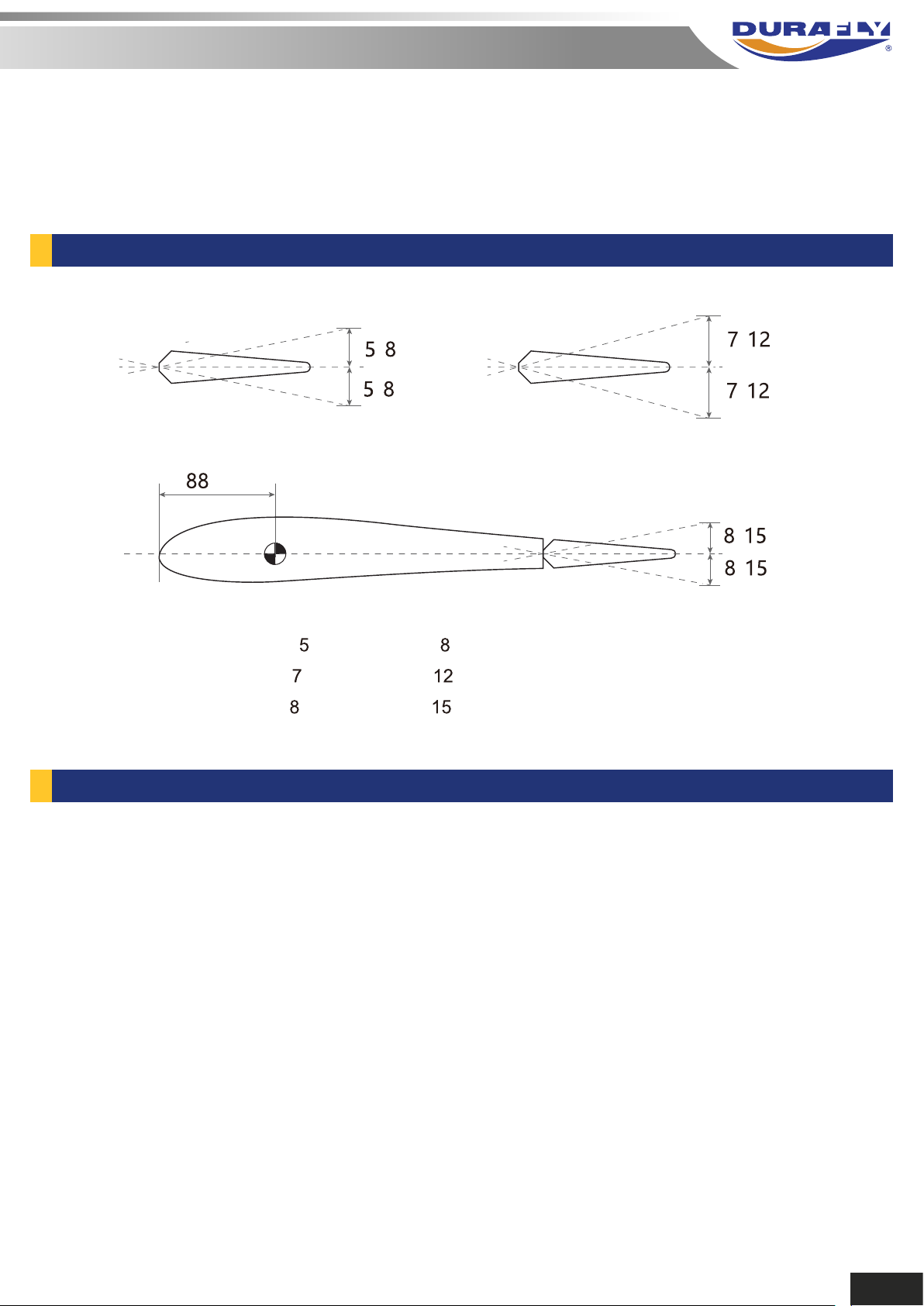
The Gladiator Mk1 handles very well in flight, and that’s not down to good design alone, but a good
pre-flight set-up too. Before you fly your Gladiator please follow the recommended settings below
for optimum handling and performance.
CONTROL THROWS:
- mm
- mm
Elevator
mm
*Elevator ‘low rates’ mm ‘high rates’ mm in either direction from neutral.
*Rudder ‘low rates’
*Aileron ‘low rates’
mm ‘high rates’ mm in either direction from neutral.
mm ‘high rates’ mm in either direction from neutral.
DECAL APPLICATION GUIDELINES:
Aileron
- mm
- mm
Rudder
- mm
- mm
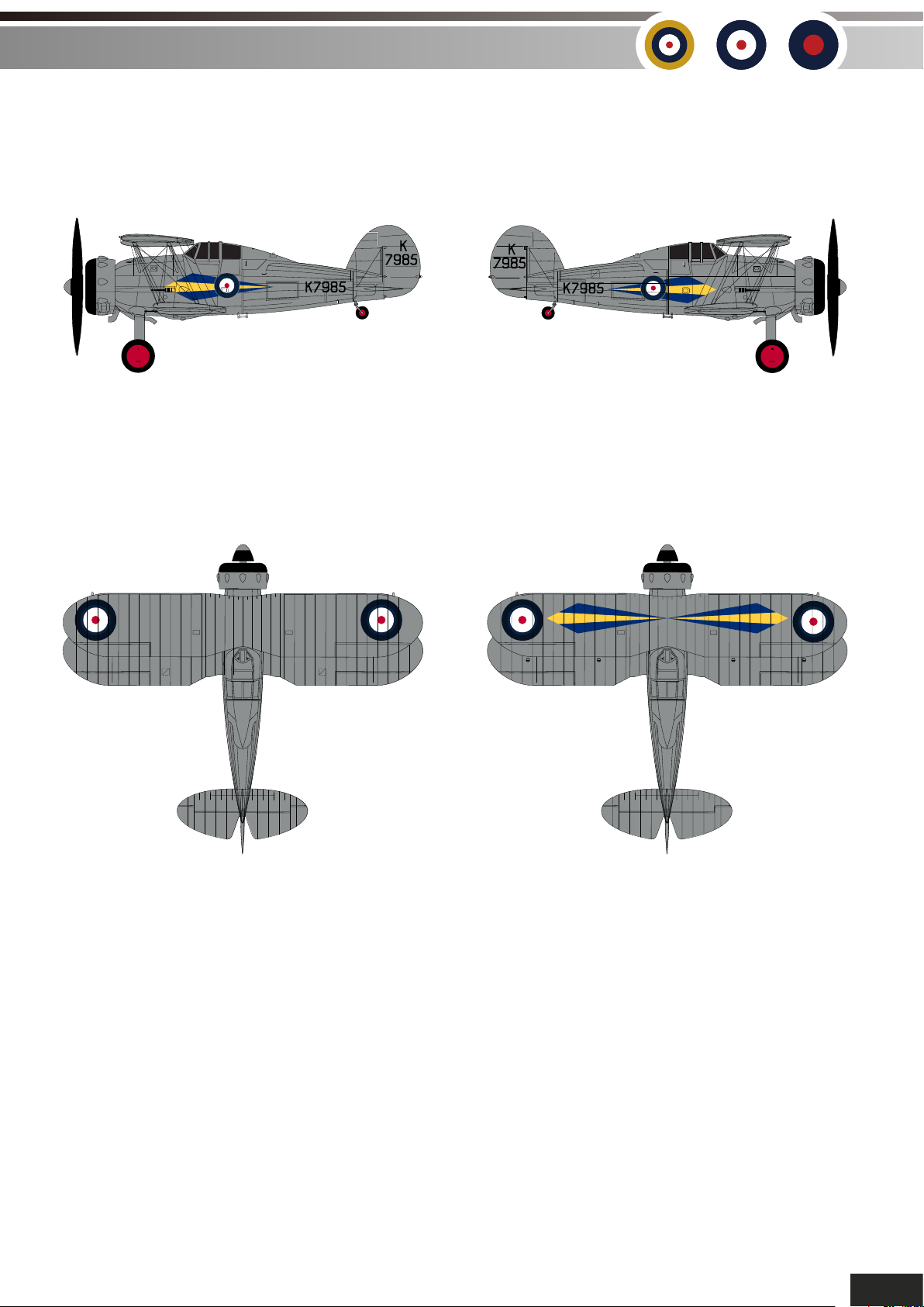
Applying the supplied decals will take you longer than assembling the model. This is because great
care must be taken when doing so. Please follow carefully the guidelines below to achieve the best
possible finish on your Gloster Gladiator.
10
Page 14
GLOSTER GLADIATOR MK1
OIL
G5/1815
GRIP
FIRST
AID
DURAFLY 1100MM PLUG AND FLY
G5/1824
CX
G5/1804
CX
LIFT HERE
G5/1824
CX
G5/1804
CX
G5/1701
CX
W
T
LIFT HERE
LIFT HERE
GRIP
FIRST
AID
OIL
G5/1815
Starboard side decalsPort side decals.
G5/1701
CX
W
T
G5/1701
CX
W
T
No STEP No STEP
DATUM
DATUM
DATUM DATUMDATUM DATUM
DATUM
DATUM
Top wing decals.Bottom wing decals.
11
Page 15
Note:
*
Study the scheme reference sheet carefully and understand fully where each decal should be
applied.
Position the decals carefully on the model according to the hen gently rub
(using a dry cloth) the decal in place
bubbles
If air bubbles are present, use the tip of a sharp blade to make a small hole in the bubble then
rub over it again to push the air out
rub from the center out to avoid wrinkles and air
12
Page 16
GLOSTER GLADIATOR MK1
DURAFLY 1100MM PLUG AND FLY
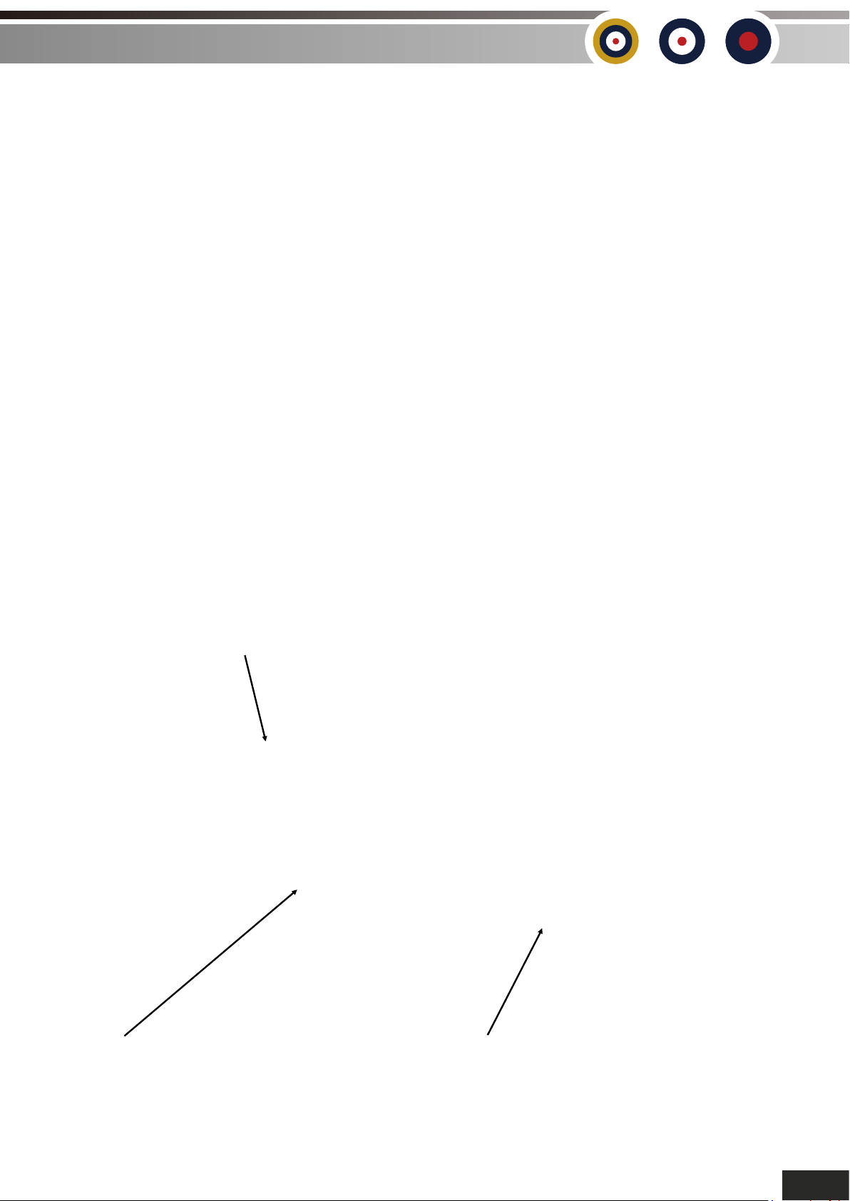
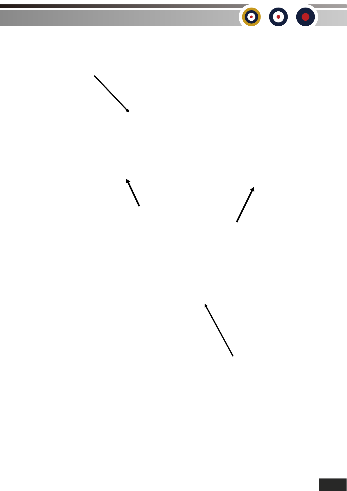
FLYING WIRE INSTALLATION
GUIDE FOR DURAFLY 1100mm GLOSTER GLADIATOR
CREATED BY TOM HUNT
#2 FUSELAGE STRUT FWD HOLE
LOWER INDB FITTING FWD-INBD HOLE
#3 LOWER FWD OUTBD FITTING#1 START
13
Page 17
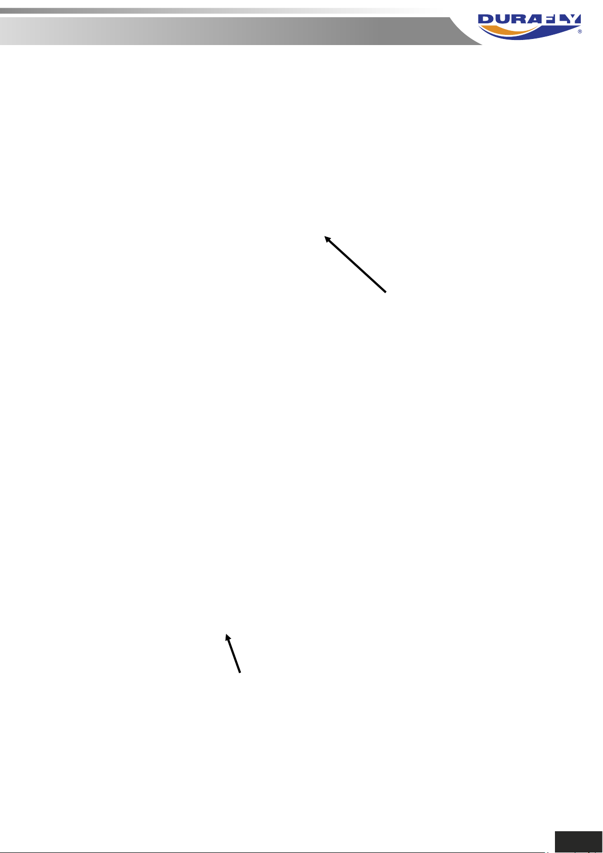
#4
UPPER AFT
OUTBD FITTING
#5
LOWER INDB FITTING
AFT-OUTBD HOLE
14
Page 18
GLOSTER GLADIATOR MK1
#7 FUSELAGE STRUT AFT HOLE
DURAFLY 1100MM PLUG AND FLY
#6 START
LOWER INDB FITTING
AFT-INBD HOLE
#8
LOWER AFT
OUTBD FITTING
#9
UPPER FWD
OUTBD FITTING
15
Page 19
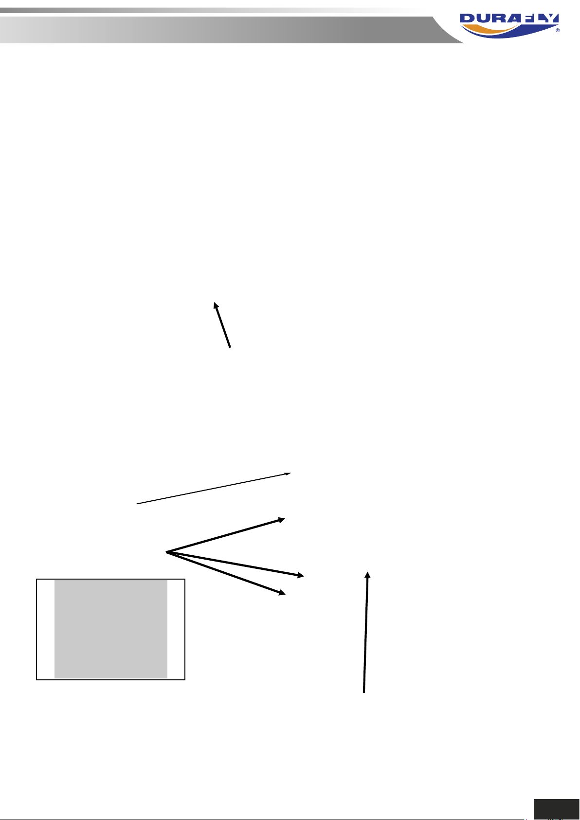
TUBE SITS BELOW
THIS WIRE
TUBE SITS ON TOP
OF THESE 3 WIRES
#10
LOWER FWD INBD FITTING
TRUE FRONT VIEW
Ø2.5 mm X 108 mm LONG FLYING WIRE STABILIZING
TUBE SUPPORT TACK GLUE TO WIRES USING FOAM
TAC, UHU PHOR OR SIMILAR. NOTE: THIS TUBE IS
OPTIONAL AND IS NOT SUPPLIED.
16
Page 20
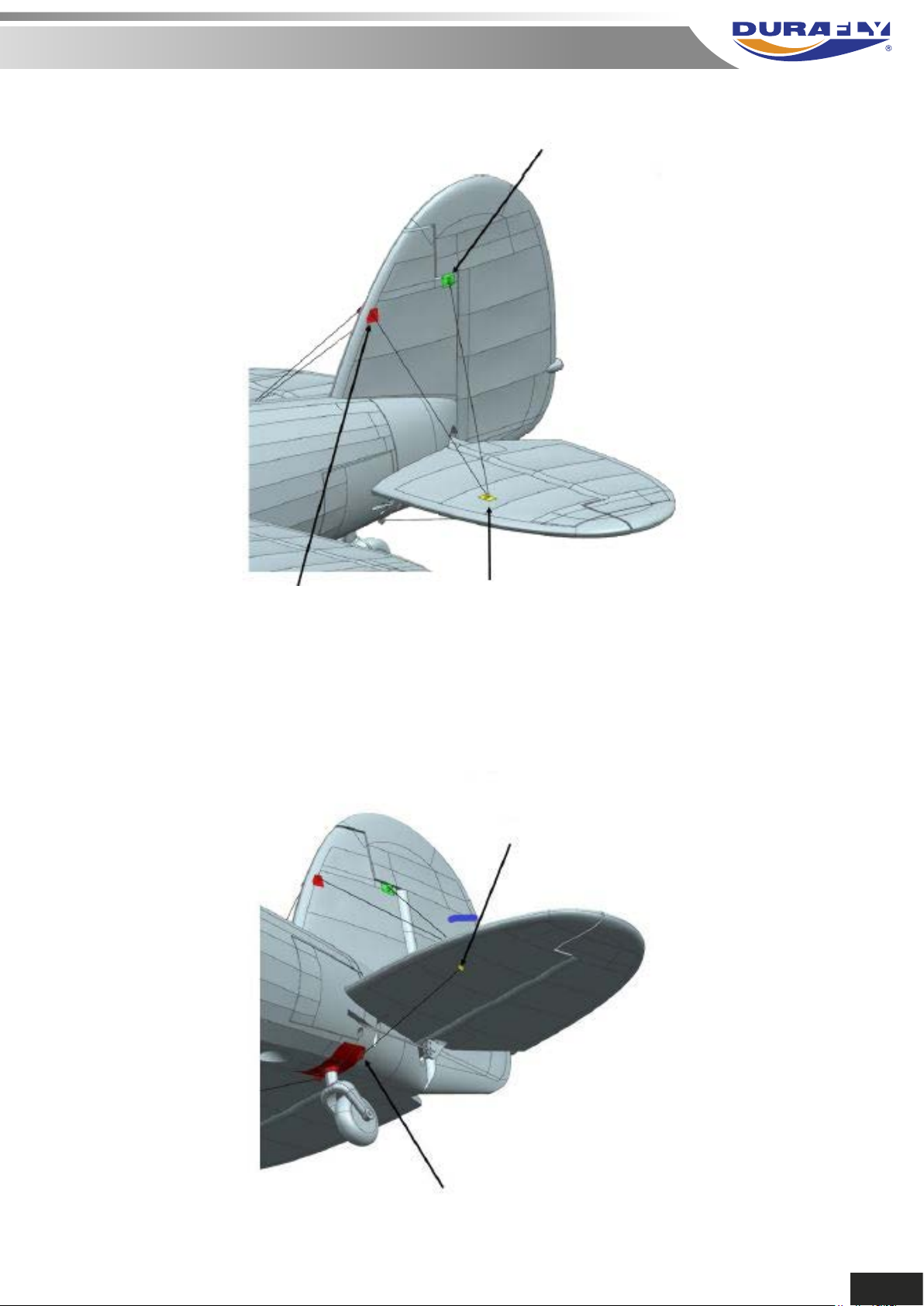
#13 TERMINATE AFT
FITTING TO VERTICAL FIN
HERE
#11 START FWD
FITTING VERTICAL
FIN
#12 OUTBD HORIZTAIL
FITTING
#15 TERMINATE LOWER HORIZTAIL
FITTING
#14 START LOWER FUSELAGE FITTING
17
Page 21
GLOSTER GLADIATOR MK1
DURAFLY 1100MM PLUG AND FLY
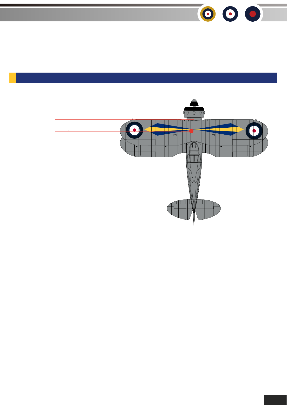
5. The center of gravity (CG) for the Gladiator is approximately 88mm from the leading edge of the
upper wing. To obtain the correct CG, the 2200mAh 4S LiPo needs to go as far forward as possible.
Once in position, the battery should be retained using the foam block supplied in the kit.
CG LOCATION:
CG 88mm
No STEP No STEP
DATUM DATUMDATUM DATUM
C of G is 88mm from the
leading edge of the upper wing.
DATUM
DATUM
DATUM
DATUM
With assembly and set-up now complete,
your Durafly Mk1 Gloster Gladiator should now be ready for flight. However
we recommend you read and follow the advice given in the following pages
of this manual before flying.
18
Page 22
MODEL FLYING PRECAUTIONS
Do not fly this model in poor
weather. High winds, low visibility, inclement temperatures, rain and storms are to be avoided.
Never attempt to catch this model whilst in flight. Even a slow
yourself and other and risks damage to the model.
This model is recommended for children no younger than 14 year old. All children, no matter what
age, should always be supervised by a capable and responsible adult when operating this model.
Always unplug your model battery when not in use. Never leave the battery installed in the model.
Remember to keep clear of the propeller at all times when your flight battery is connected.
Before flying, always turn on your transmitter first then plug your flight battery into the model.
After flying, always unplug your flight battery first then turn off your radio transmitter.
Exercise caution when charging your batteries and follow in full your battery manufacturers
safety guidelines when doing so.
moving model can cause harm to
PRE-FLIGHT CHECKS
Always range check your models radio before any flight (especially when flying a new model for
the first time). Follow your radio manufacturers guidelines for performing this check.
Check all screw /bolts and mounting points are firmly secured, including control horns and
.
Only fly with fully charged batteries (both in your radio and model). Failure to do so could result
in loss of control, damage to the model and/or persons/property around you. Check your
batteries are fully charged.
With the model powered up (transmitter on first, then receiver/model) check that all surface are
free from damage/obstructions, moving in the correct directions and freely with
Inspect the model and prop for any damage that may have occurred during transit and listen for
any unusual sounds from the electronics when powered up. If in doubt, do not fly.
With the model held securely and the prop free of obstructions, increase the throttle just slightly
to confirm the rotation of the prop is correct. The model should want to pull straight forward with
throttle.
If this is your first flight with the model double check the C/G is at the correct position. If not adjust
battery position inside model accordingly.
If you are an inexperienced model pilot then seek the help and assistance of an experienced
pilot to perform these final checks, and to test fly the model for you.
19
Page 23
GLOSTER GLADIATOR MK1
DURAFLY 1100MM PLUG AND FLY
FLYING YOUR MK1.
Before flying make sure you have followed closely the set-up guidelines on page 10, and pages
17-18. Start by taxying on the ground a little to get used to the handling. Be sure to always taxy
with full up elevator, use high rates and gentle use of the throttle. This will keep the model tracking
steady and true plus has the added bonus of looking far more scale. For take off you'll want to
hold in some right rudder to counter the rotational torque on the initial roll out. Slowly advance the
throttle whilst holding in just a little up elevator to keep the tail down as you begin to build up
speed, correcting direction with rudder as needed. As speed builds, ease off the amount of up
elevator you have held in, then as soon as you reach 1/2 to 3/4 throttle you'll start to see the
Gladiator gently lift of the ground.
Once in the air
Of course opening up to full throttle is very exciting,
but generally
. A full 'airshow' routine can be performed including loops, rolls, low banked passes,
S t-S's etc, all vertical man euv s as large as you wish with the 4S set-up.
Flight times vary according to and throttle use. An average flight of mixed
throttle flying will give you approximately -
Your stall is benign easily recovered from at
height by centering all sticks and a pplication of power.
Landing the Mk1 is a pleasure and a real treat for those who like to practice
'scale' type approaches as the to be 'flown' onto the deck through a
powered decent Once you have the fully lined up to the runway
and
good throttle management
be sure to use
20
Page 24
Mk1 TIPS
Thank you again for purchasing the Durafly .
We hope you’ll have many happy days of flying and look forward to
bringing you more Durafly models in the future.
Don’t forget, spare parts are available for this model,
please see the next page for details.
21
Page 25
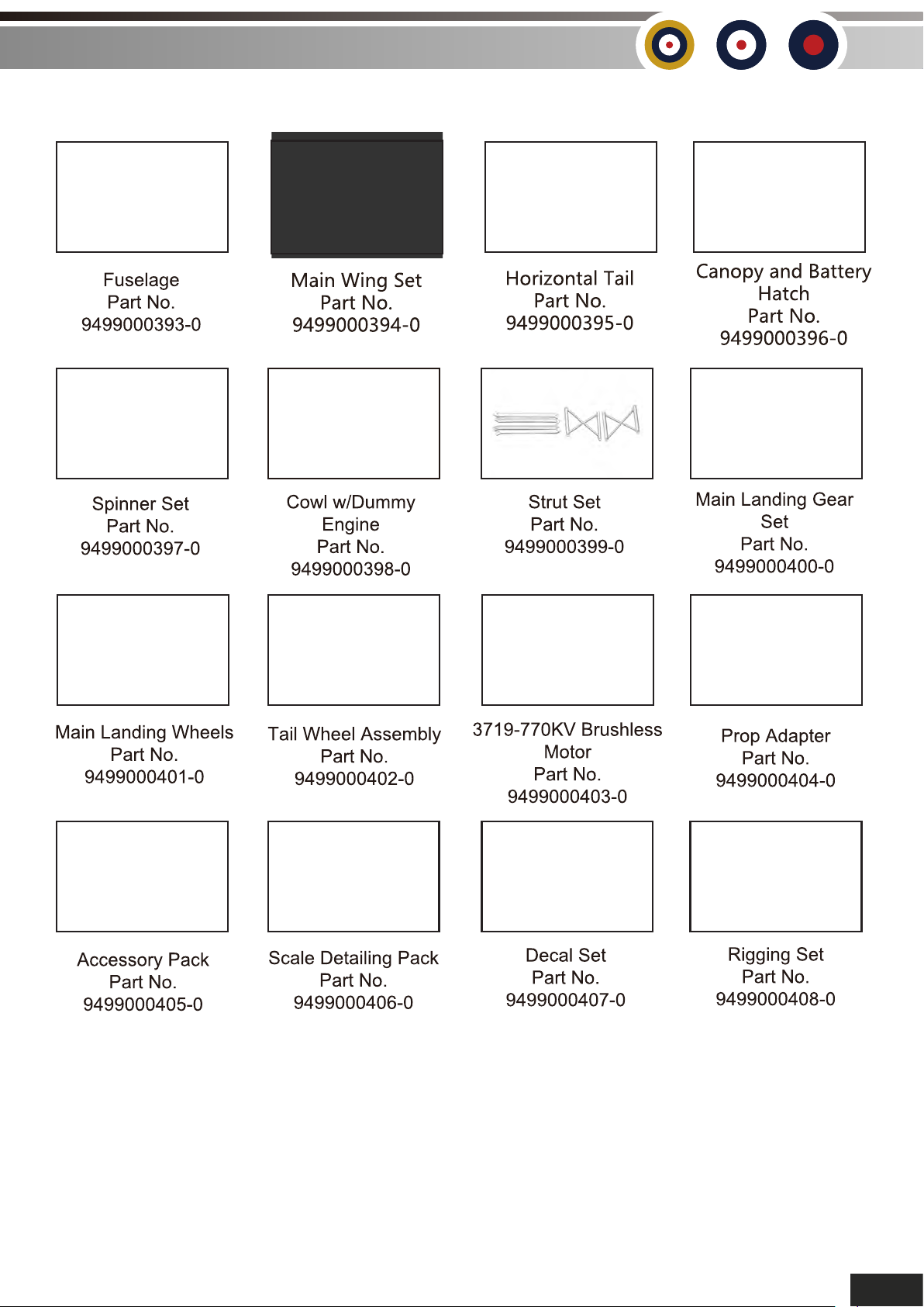
GLOSTER GLADIATOR MK1
SPARE PARTS
DURAFLY 1100MM PLUG AND FLY
22
Page 26
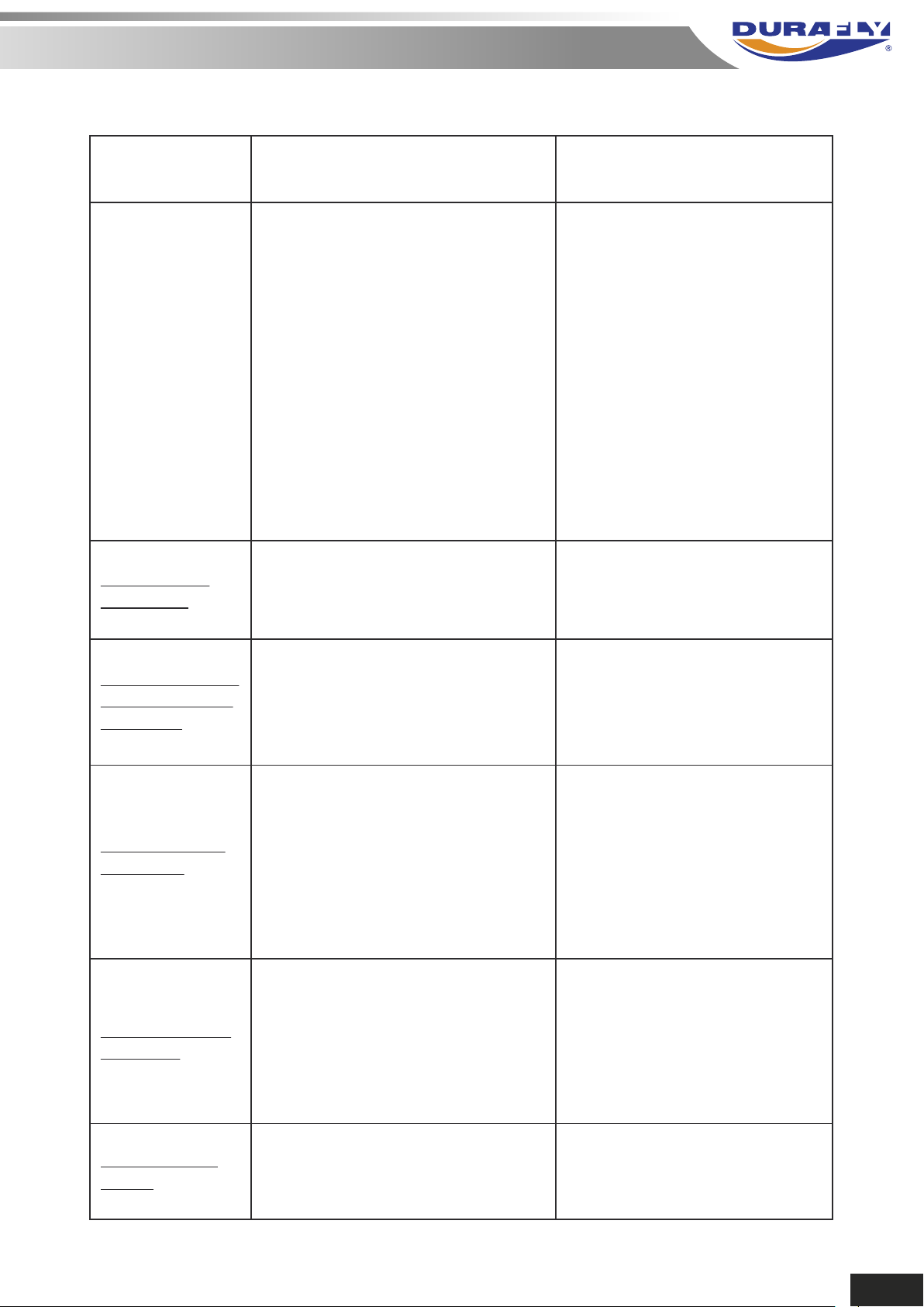
TROUBLE SHOOTING:
Problem Cause Solution
Motor does
not turn
Model moves
backwards
Control surfaces
not moving with
stick input
1. Battery is not fully charged.
2. Transmitter battery low.
3. Motors not connected.
4. The motor is damaged.
5. Receiver is not bound to Tx.
6. ESC in set-up mode.
1. Prop installed backwards
1. The servo lead is connected
to Rx incorrectly.
2. The servo is damaged.
1. Charge the batteries.
2. Install a full charged battery.
3. Check for connection
between the ESC and motor.
4. Replace motor.
5. Consult Radio manual and
go through bind procedure
again.
6. Hold model and move
throttle to full position then
back down to idle.
1. Turn the prop around.
1. Make sure the servo leads
are connect properly.
2. Replace servo.
Model does not
fly straight
Model does not
climb well
Limited Radio
Range
1. Control surfaces not centered.
CoG is not in the correct position.
2.
1. The battery is not fully charged.
2. Elevator servo is reversed.
3. CG too far backwards.
1. Transmitter/Receiver batteries
are flat.
1. Adjust the trims on the
transmitter.
2. Re-position lipo as
suggested.
1. Charge the battery.
2. Change servo direction via Tx.
3. Move battery forwards.
1. Charge/replace batteries.
23
Page 27
GLOSTER GLADIATOR MK1
If you wish to contact us directly please email:
DURAFLY 1100MM PLUG AND FLY
24
Page 28

UK REP
EC REP
APEX CE SPECIALISTS LIMITED
M1 4HT, UK
APEX CE SPECIALISTS LIMITED
 Loading...