

Page 1
Page 2

Features of the Bravado
1. ‘AirCore’ construction resulting in both a lightweight, yet strong structure.
2. Powerful set-up as standard for hardcore 3D and aerobatic performance.
3.Quick and easy assembly with minimum parts count.
4. Clean airframe design with easy battery access and generously sized control surfaces.
5. Made from durable and easy to maintain EPO foam and with spare parts readily available.
Specifications
Wingspan: 1000mm ( 39.4 in.)
Flying Weight: 700-780g (1.5 -1.7lbs)
Motor: 2814 Kv1000
ESC: 40 Amp
Servo: 4 x Turnigy TG9d 9g digital servo’s
Radio:4/more channel
Receiver: 4/more channel
Battery: 3 cell 1000-1300mah lipo 25c min (required)
Prop: 11x
Recommended Environment: Outdoor/large indoor area.
Assembly Time: Less than 1 Hour
Examine your kit carefully
Durafly model kits are subject to QC checks throughout production, and we sincerely hope that
you are completely satisfied with the contents of your kit. However, before assembling, we ask that
you check all parts against the parts list. If you are missing any parts, please contact Customer
Services via hobbyking.com. Also check for any damage to the any item within the box. Your model
has travelled a long way, and in some case could have sustained some damage. If you feel the
damage is beyond ressonable repare, please contact CS.
Please note:
We are constantly working on improving our models, therefore every model is subject to change
without notice.
This is a sophisticated hobby product and is NOT a toy. It must always be operated with caution,
common sense and some basic mechanical ability. This manual provides instructions as the the
assembly, safe opperation and maintainence of this hobby product. It is highly reccommneded that
you follow and read fullythe instructions and warnings stated in this manual including, safety,
assembly, set-up and flying guidelines in order to operate this product correctly and avoid damage
or serious injury.
Page 3
Do not fly under the conditions below
• Strong winds (more than 20pmh)
• Other storm like conditions
• Area close to high voltage wires
• Area with high density population
Cautions for flying
While parks make excellent flying areas, make sure you have permission to fly there and follow safety
guidelines set by local authorities.
Note for Storage
• Never leave you flight battery installed in the model when storing.
• If hanging the model, ensure the control surfaces are not taking the weight of the model.
• Store away from direct sunlight and ideally at room temperature.
• Secure your model for storage incase it moves and gets damaged.
Tools:
Required: Scissors, Balsa knife, Combination pliers, Screwdriver, Quick-dry glue
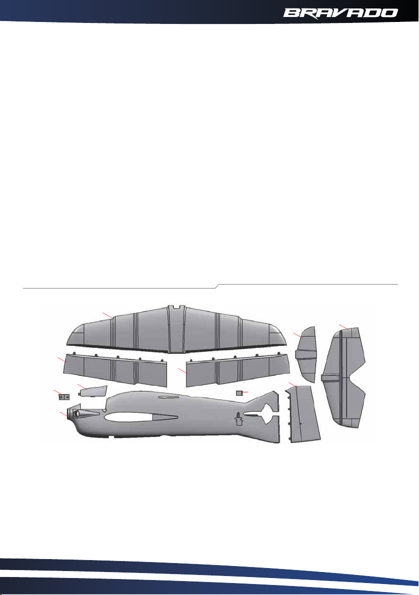
Foam parts included in the packing
2
5
10
3
3
8
9
9
1
1. Fuselage
4. Right aileron
7. Rudder bolt
10.Stabilizer
2. Wing
5. Winglet
8. Canopy
4
6
7
3. Left aileron
6. Rudder
9. Landing gear slice
02
Page 4
Parts included in the packing
12
17
16
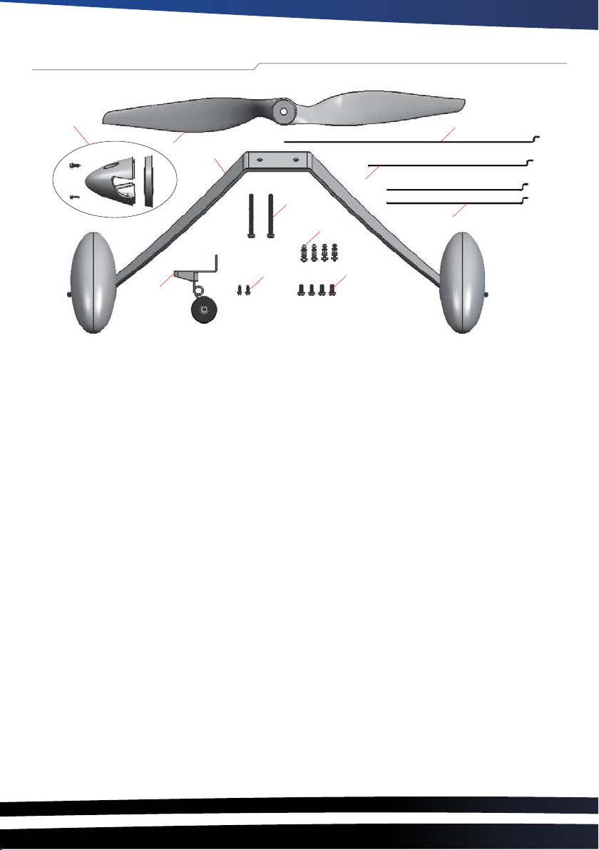
11.Landing gear
12. Spinner
13. Screw (M4*30)
14. Screw (M2*5)
15. Adjustor
11
19
13
15
14
16. Tail wheel
17. 1155 propeller
18. Rudder pushrod (φ1.2 piano wire)
19. Elevator pushrod (φ1.2 piano wire)
20. Aileron pushrod (φ1.2 piano wire)
21. Screw (M3*8)
21
18
20
Page 5
Assembly steps
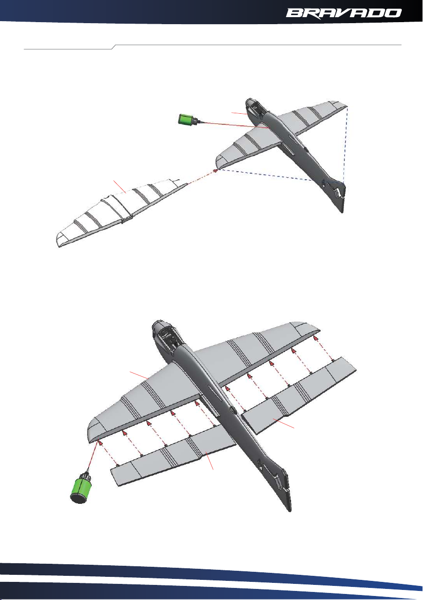
1. Aseembly begins with the wing (2) and fuselage (1). Incert the wing panel into the slot in the
fuselage and glue in place. Insure that distance A is equal to B.
1
B
2
2. Hinges (4 for each side) can now be glued into the pre-cut slots of the trailing edge of the wing
(2). Once dryed you can then glue the ailerons(3&4) to the hinges.
A
2
4
3
04
Page 6
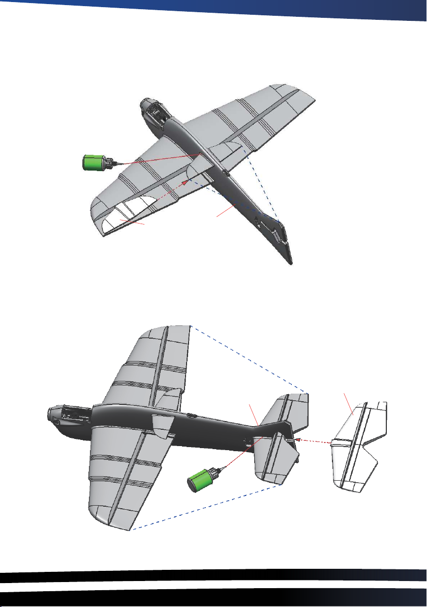
3. Insert the fuselage winglet (5) into the upper fusealge slot and glue in place.
Ensure distance C is equal to D.
D
C
5
4. The horizontal tail (17)can now be glued in place at the rear of the fusealge asr shown.
Ensure distances E and F are equal and that the tail is horizontally level.
1
F
17
1
E
Page 7
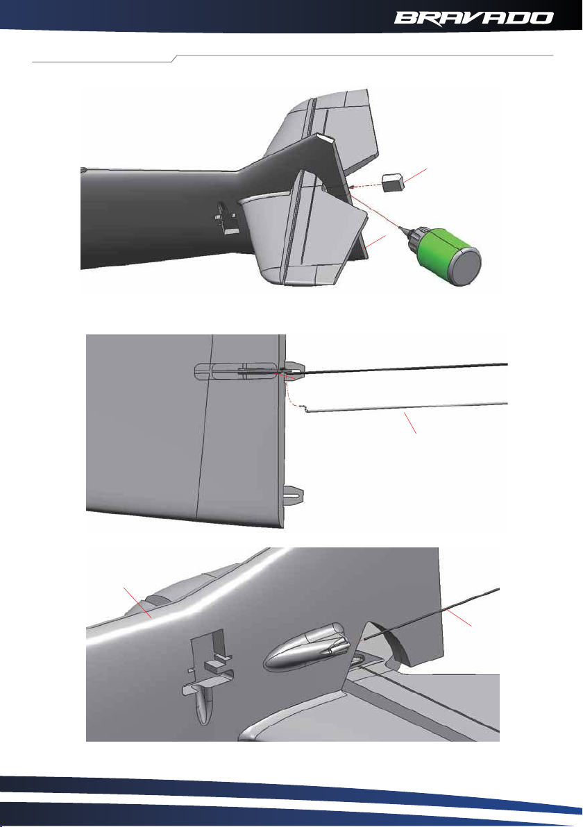
Fuselage Assembly
5. Place vertial trailing edge insert (7) into pre-cut slot at the rear of fuselage, then fix with glue.
7
1
6. Connect Z bend (18) to servo control horn on rudder (6), then push pushrod into pushrod tube.
6
18
1
18
06
Page 8
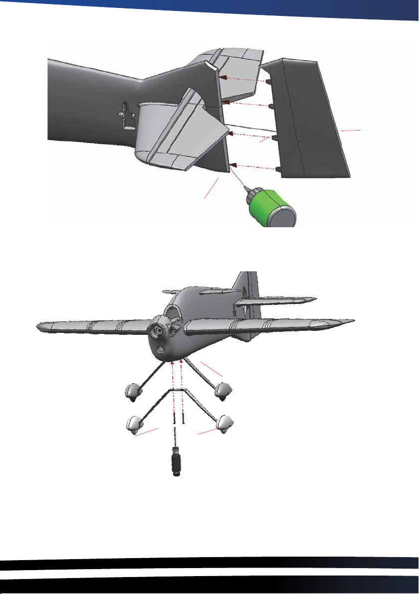
7. Glue 4 hinges into the rudder (6) then glue the rudder to the vertical tail (1) as shown below.
18
1
8. With the rudder in place the landing gear (11) can now be installed. Locate the supplied
M4x25mm bolts (13) and secure to the fuselage (1) using a screw driver as shown.
1
6
13
11
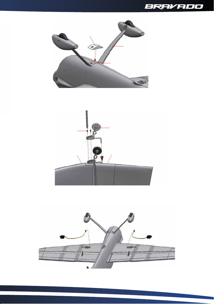
9. Once the landing gear (11) is secured, the gear foam cover (12) can be installed as shown with just
a small spot of glue.
Page 9
12
11
13
10. Locate the tail wheel assembly and install as detailed below using the supplied M2x5mm screws.
14
1
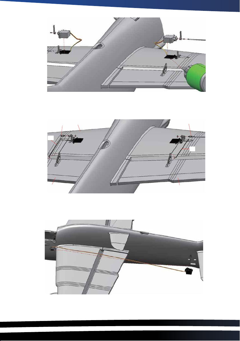
11. Install your 9g servo’s of choice into the molded pockets on the underside of the wing by guiding the
wires through into the center of the fuselage and securing in place with some glue as shown below.
16
6
KIT ONLY
08
Page 10
KIT ONLY
12. Glue the aileron control horn in place and connect the Z bend push rods (20) as shown. Ensure that your
servo horns are at 90 degree’s to the wing at this stage.
15
20
4
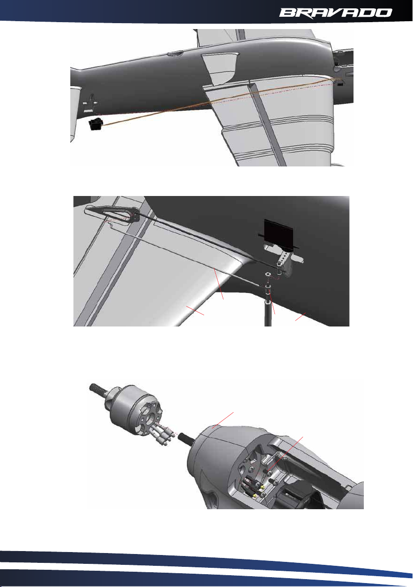
13. Your 9g rudder and elevator servo of choice can now be glued in place in the pre-molded pockets on
either side of the rear fuselage. NOTE, you must ensure your servo leads are long enough to reach the front
of the model, you may need to add extension leads so please check.
2
15
20
3
KIT ONLY
Page 11
KIT ONLY
14. Both the rudder (not shown) and the elevator push-rod Z bend and control horn can now also be install
just as before. Again ensure your servo horn is at 90 degree’s to the fusealge.
19
17
15
1
15. Install your choice of 2814 class motor onto the firewall as show below. It is suggested that thread lock
be used.
1
21
KIT ONLY
10
Page 12
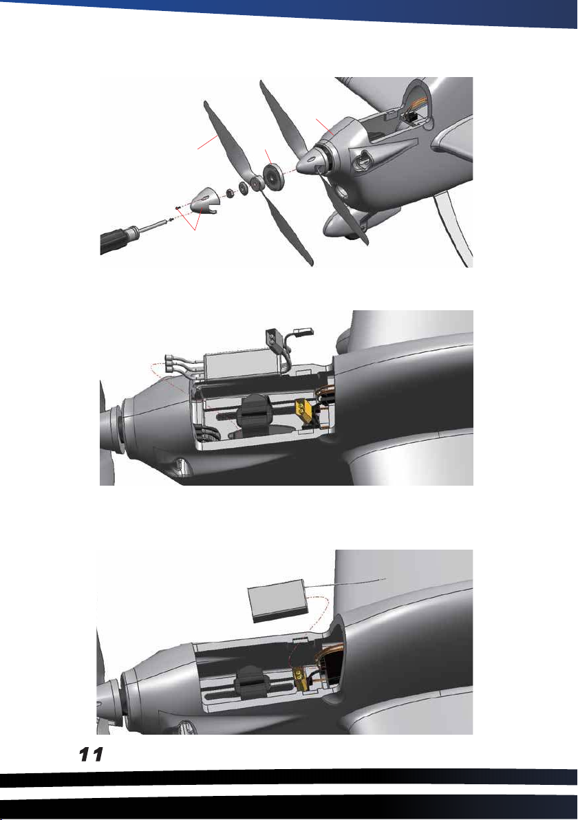
16. Locate the spinner assembly and first slide the spinner back plate (9) on the motor shaft followed
by theprop (10), washer and nut as shown. Firmly tighen the nut and finishby screwing the
spinner tip (9) in place.
1
10
9
9
17. Install your 30-40amp ESC of choice in the nose of the fuselage under the plastic battery tray as
detailed below.
KIT ONLY
18. Connect servo wires to coorisponding channels of your receiver and install directly behind the battery
tray on top of th wing center section. Secure in place with velcro.
Page 13
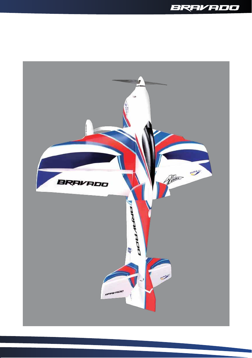
Assembly of your Durafly Bravado is now complete.
Before you move onto the final set-up of the model, we suggest
you perform a final check on all screws, bolts and components to
ensure all are secture and firmly in place.
12
Page 14
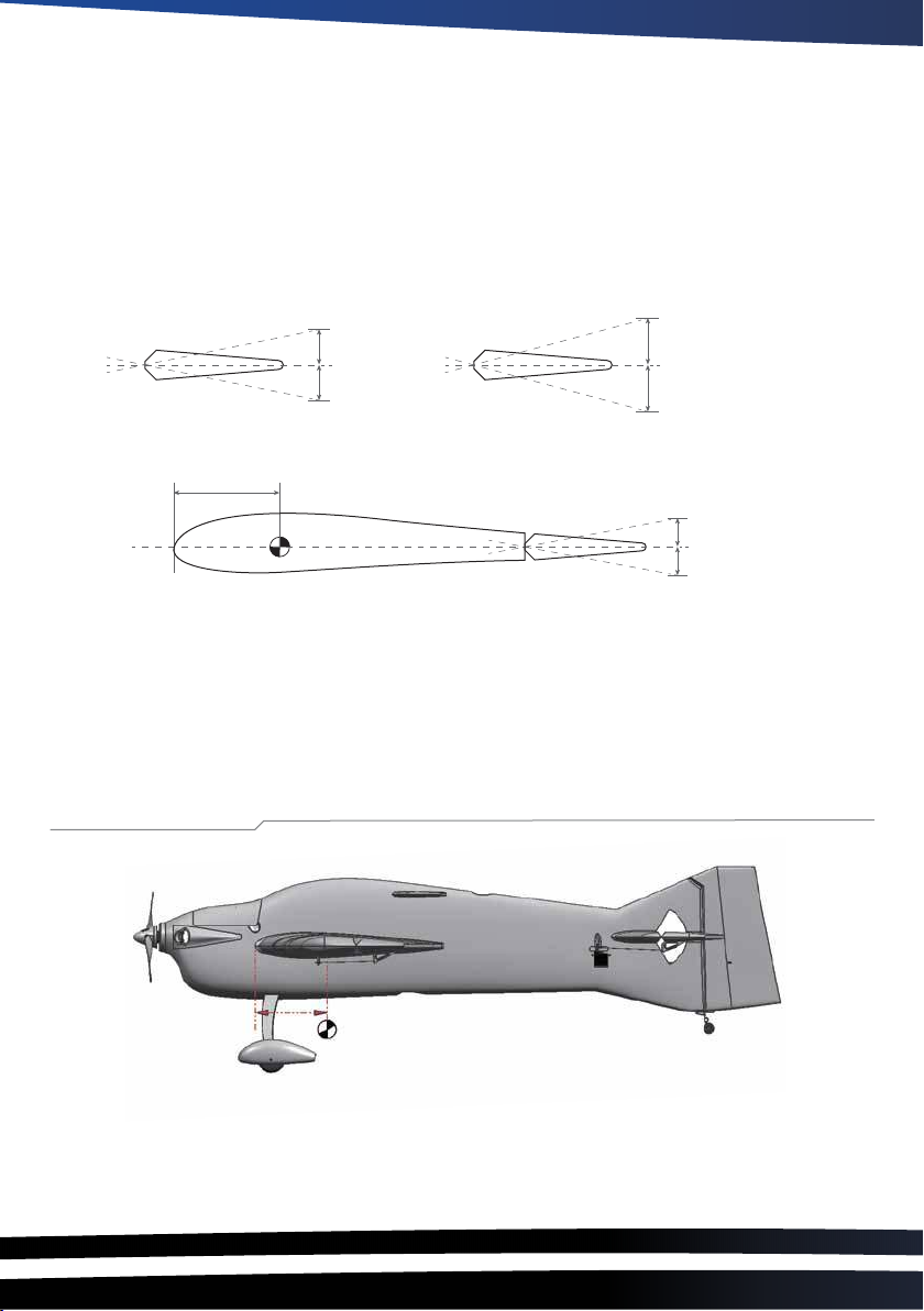
CG 120-130mm
1. With your receiver installed and all servos plugged into their corresponding channels, connect the
flight battery to the ESC to power up the model. With the model now armed, ensure all servo’s are
centered and all control surfaces are level. If not, adjust by turning the control clevis’s by hand
accordingly until the control surfaces are level as shown.
Note: For saftey reasons, it is advised that this is done with the prop removed from the model.
Control throws:
6 -8 mm
6 -8 mm
6 - 10 mm
6 - 10 mm
Elevator
90-95 mm ~
8 -12 mm
8-12 mm
Rudder
Aileron
* Elevator ‘low rates’ 15mm ‘high rates’ 30mm in either direction from neutral. (travel, 120% up and 100% down)
* Aileron ‘low rates’ 10mm ‘high rates’ 15mm in either direction from neutral.
* Rudder ‘low rates’ 15mm ‘high rates’ 25mm in either direction from neutral.
Center of Gravity
The centre of gravity (CG) should be at a position of 120mm-130mm away from leading edge, please
refer to above picture.
Page 15
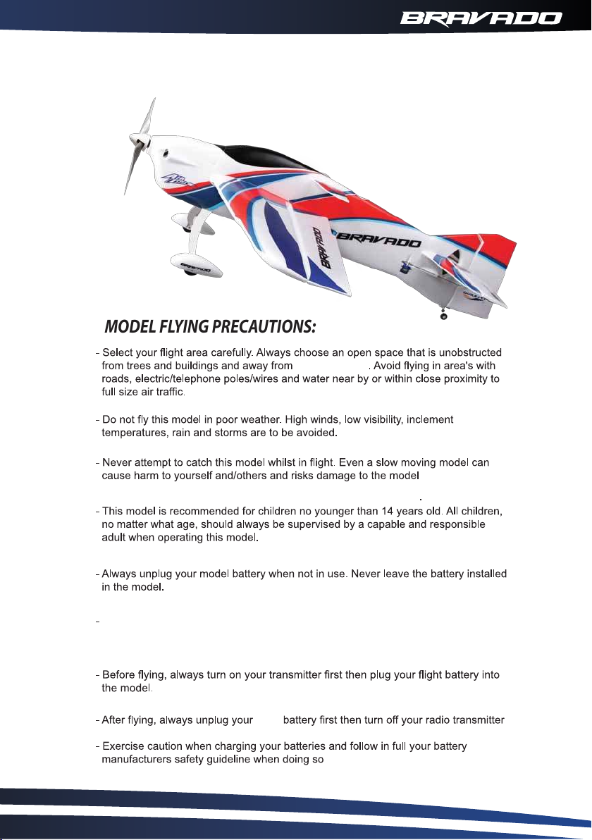
should now be ready for flight. However we recommend you read and follow the
With assembly and set-up now complete your Durafly Bravado
advice given in thefollowing stages of this manual before flying your model.
MODEL FLYING PRECAUTIONS:
crowded areas
Remember to keep clear of the propeller at all times when your flight battery is
connected.
flight
14
Page 16
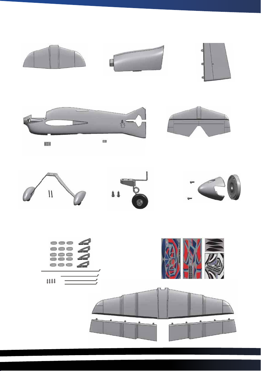
Spare parts
Winglet
9095000104-0
Canopy
9095000115-0
Rudder
9095000106-0
Fuselage
9095000102-0
Landing gear
9095000107-0
Control accessories set
9095000116-0
Tail Wheel
9095000108-0
Stabilizer
9095000105-0
Spinner
9095000107-0
Sticker Set
9095000113-0
Wing
9095000103-0
Page 17

Page 18

 Loading...