

Page 1
INSTRUION MANUAL
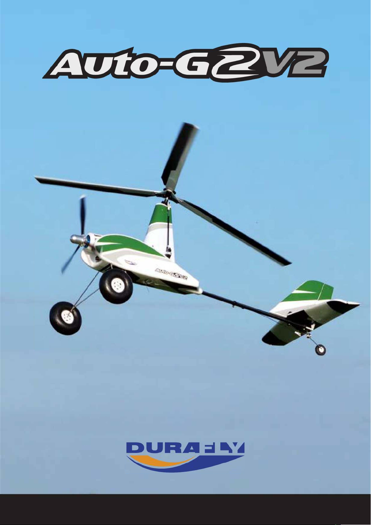
Please read this manual carefully before operating this plane.
Page 2
Page 3

CONTENTS
Introduction -------------------------------------------------------------------- 1
Specifications ----------------------------------------------------------------- 1
Kit Contents ------------------------------------------------------------------- 2
Required to complete the model ----------------------------------------- 2
Assembly -------------------------------------------------------------------- 3-7
Setting up the Auto-G2 V2 ------------------------------------------------ 8
C of G location --------------------------------------------------------------- 9
Model flying precautions -------------------------------------------------- 9
Pre-flight checks ------------------------------------------------------------ 9
Flying the Auto-G2 V2 ----------------------------------------------------10
Spare parts list ------------------------------------------------------------- 11
Trouble shooting ----------------------------------------------------------- 12
Contacts ----------------------------------------------------------------------13
Notes ----------------------------------------------------------------------13-15
Page 4
INTRODUCTION:
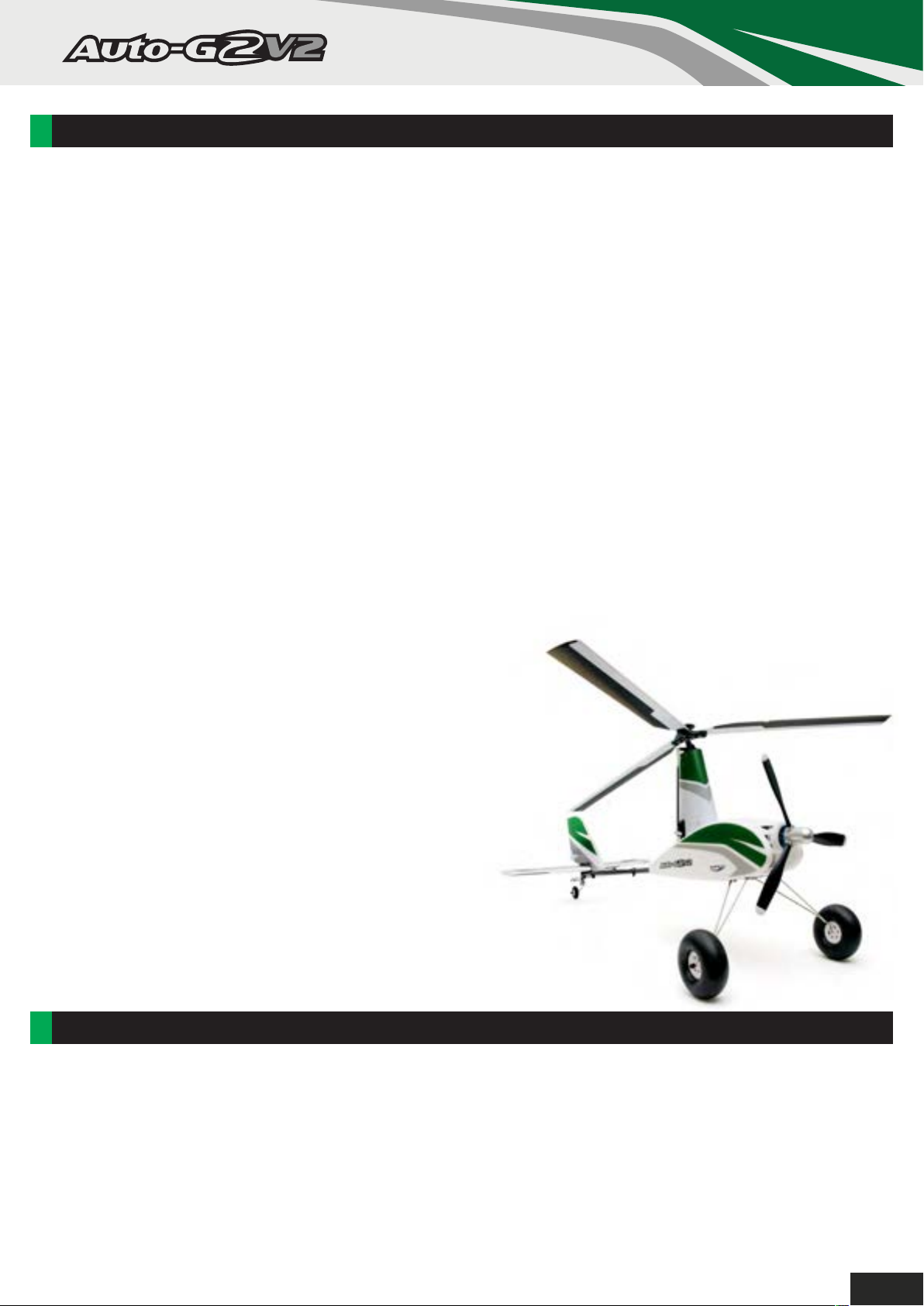
Thank you for choosing the Auto-G2 V2 gyro-copter. The Auto-G2 V2 will bring you a flying experience like
no other, it is pure fun to fly and have you smiling every time the wheels lift into the air. The original Auto-G
raised the bar by being the first Plug-N-Fly autogyro on the market, the Auto-G2 V2 has raised that bar
even higher. It is still very simple to assemble, looks amazing, and is brilliant fun to fly, in fact, it is
everything you have come to expect from the Durafly brand.
Take-offs are very straightforward as the Auto-G2 V2 has an auto-start rotor run-up system. This system
uses a small electric motor which you engage via a separate channel to spin up the rotors prior to take-off.
Once up to speed you perform a normal take-off, the one-way bearing assembly allows the rotors to spin
even faster as you accelerate and once airborne you switch the run-up motor off. Landings are a dream,
you can land the Auto-G2 V2 very similar to a conventional fixed-wing model. But with practice, very short
almost vertical landings are achievable with next to no ground run.
Autogyros are very unique aircraft utilizing an unpowered free-spinning main rotor to develop lift, and a
powered propeller to provide thrust. This makes them quite different from traditional fixed wing aircraft. The
Auto-G2 V2 offers you this very interesting design in an easy and simple to use plug and fly model.
For those of you looking for a new flying experience, the Auto-G2 V2 is just the ticket. This model will be
especially appealing to those who fly both helicopters and fixed wing aircraft as this model falls somewhere
between the two. With its very unique flight characteristics, the Auto-G2 V2 is by far one of the most
interesting models you'll ever have flown. In addition to its super slow flight and auto-rotation capability, it
can even perform simple aerobatics such as gentle stall turns.
This being the Auto-G2 V2, it has the following
improvements over the original version.
• Upgraded more durable rotor-head plate.
• Fibre reinforced pushrods.
• The rotor mast has now be fully encased and is more streamlined.
• Landing gear is wider giving more stability on the ground.
• Larger wheels so that it can be flown off of a variety of flying strips
• Landing gear has been braced to make it stronger.
• Motor has been cowled in.
• New color scheme.
• 3D printed pilots head.
The Auto-G2 V2 has been designed for intermediate and
experienced model pilots, so you will need some experience in
assembling, and flying models.
SPECIFICATIONS:
• Length : 795mm (31.3 inch)
• Height : 392mm (15.43 inch)
• Weight : 720g
• ESC : Durafly 20A brushless ESC
• Motor : Brushless motor x 1 (8OOkv)
• Servo : 9g x 4
• Radio : 5+ Channel
• Rotor Diameter (Three rotor blades) : 821 mm (2.33 inch)
• Battery : LiPo 11.1 v 1300mAh 30-50C x 1
1
Page 5
CONTENT:
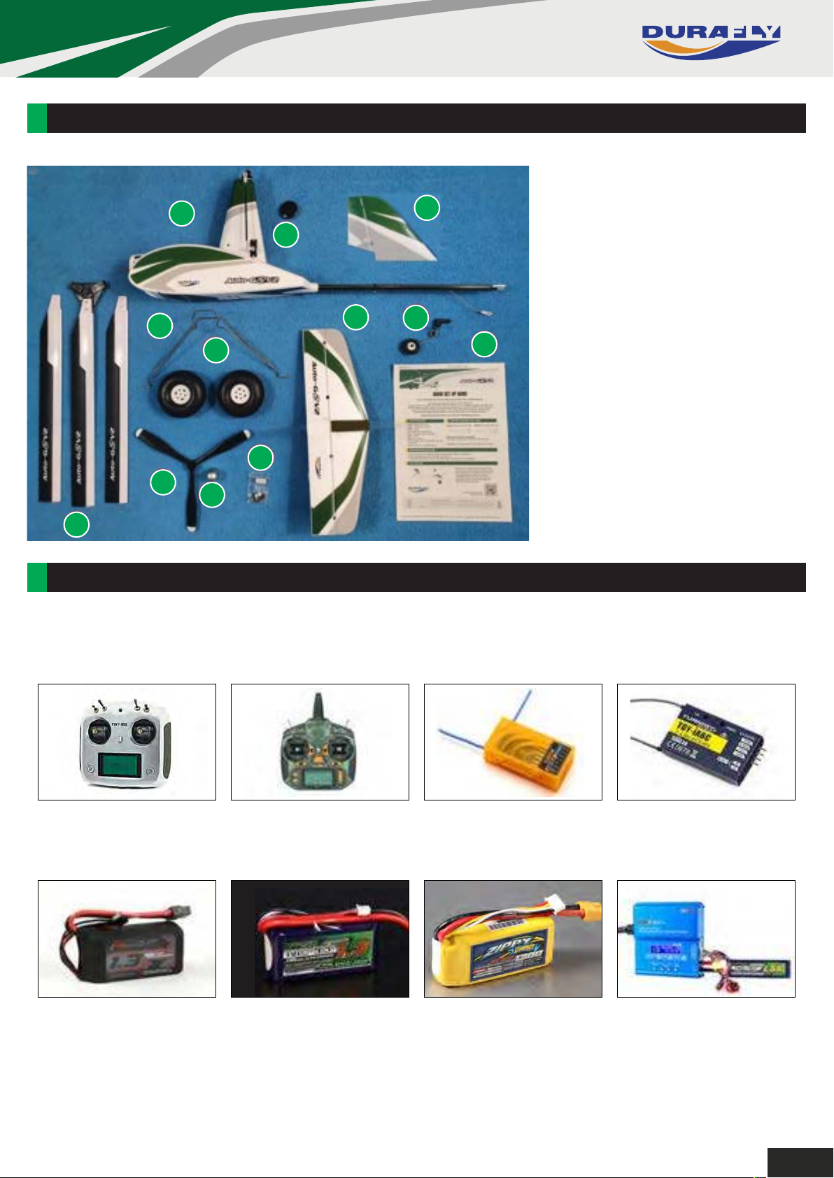
4
1.
Fuselage
1
3
2.
Rotor-Head Button
2
3.
Vertical Stabilizer
4.
Rotor Blades & Rotor Head
5.
7
9
8
10
12
11
5
Propeller
6.
Spinner
7.
Landing Gear
8.
Wheels
9.
Horizontal Stabilizer
10.
Tail Wheel Assembly
11.
Accessory Pack
6
12.
Quick Start Guide
REQUIRED TO COMPLETE MODEL:
In its ‘Plug-N-Fly’ format the Auto-G2 V2 will still require some additional accessories to get it ‘flight
ready’. Durafly recommends the products below for optimum performance and great value. All are
available at HobbyKing.com
Turnigy TGY-i6S Digital
Proportional Radio Control
System
SKU: 9114000053-0
OrangeRx Tx10i Mode 1 EU
Version 10ch 2.4GHz DSMX
Compatible Radio System
SKU: 9171001398-0
OrangeRx R615X DSM2/DSMX
Compatible 6Ch 2.4GHz Receiver
SKU: 9101800001-0
Turnigy iA6C PPM/ SBUS 8CH 2.4G
AFHDS 2A Telemetry Receiver
SKU: 9114000063-00
Turnigy Graphene 1300mAh
3S 45C LiPo Pack w/ XT60
SKU: 9067000125-0
Turnigy Nano-Tech
1300mah 3S 25~50C Lipo Pack
SKU: N1300.3S.25
ZIPPY Compact 1300mAh 3S 25C
Lipo Pack
SKU: ZC.1300.3S.25
IMAX B6AC V2 Professional
Balance Charger/Discharger
SKU: 9052000068-2
2
Page 6
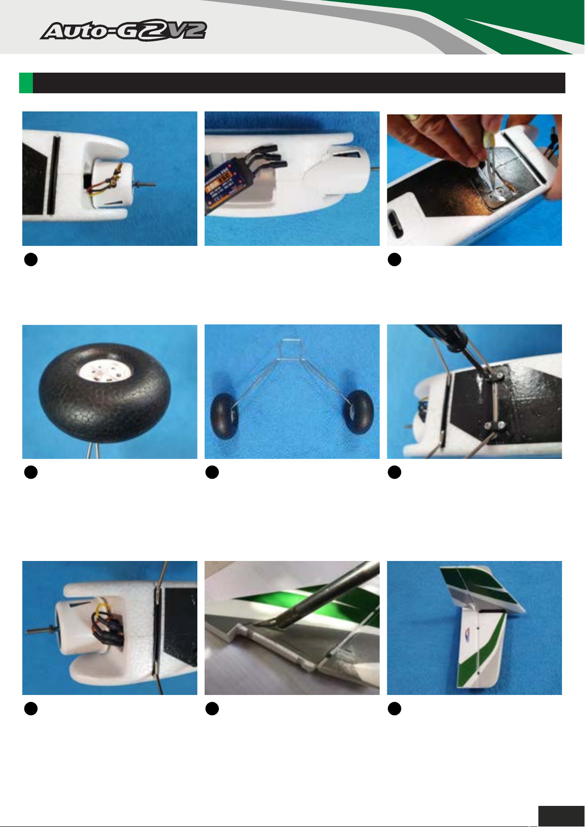
ASSEMBLY (PNF):
1
The first step in the assembly is to fit the landing gear, your ESC
to motor wires should be supplied disconnected. If not, then unplug
the ESC from the motor and slide the ESC wires out of the way of
the area where the landing gear is attached.
3
3 Attach the wheels to the landing
gear and retain using the white
plastic screw-on domed fittings.
4
3 Landing gear ready to be
attached. Tip: Use some silicone
grease on the axles, this will
reduce the acoustics caused by
the large wheels whilst flying.
2
With a sharp knife, remove the
covering over the rear landing
gear slot as shown.
5
Squeeze the front of the landing
gear into the front slot (this is quite
a tight fit). Retain the rear cross
brace using the black landing gear
straps and the 4 x self-tapping
screws provided.
6
3 Feed the ESC cables back
through the landing gear and plug
into the motor connectors, don't
forget to check the motor rotation
when you get to setting up your
radio.
7
3 Before gluing the vertical
stabilizer to the horizontal stabilizer,
remove the covering from the area
shown with a sharp knife.
8
Glue the vertical stabilizer to
the horizontal stabilizer.
3
Page 7
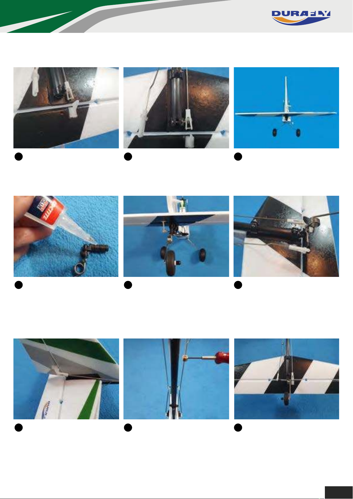
9
Slide the tail assembly onto
the tail boom, position the rear
clamp so that it is flush with the
end of the boom.
10
Using the M2 x 10mm nuts
and bolts provided, clamp the
tail assembly to the tail boom.
11
Check before fully tightening
the bolts that the assembly is in
alignment to the rotor mast.
12
3 Apply a spot of glue to the
spigot on the tail wheel assembly
then side it into the end of the tail
boom.
153 Connect the rudder pushrod
clevis the the rudder horn. Ensure
on all the clevises you slide the
rubber security keeper up as close
to the clevis pin as possible.
13
3 Check the alignment of the tail
wheel assembly as the glue sets,
ensure it remains perpendicular to
the tail assembly.
16
3 Centralize the rudder, then
slacken the grub-screw of the tail
wheel control rod collet, centralize
the tail wheel then re-tighten the
screw.
14
Connect the tail wheel and
elevator horns to the pushrod
clevises.
17
Make sure that the tail wheel is
in-line with the tail boom when the
rudder is central.
4
Page 8
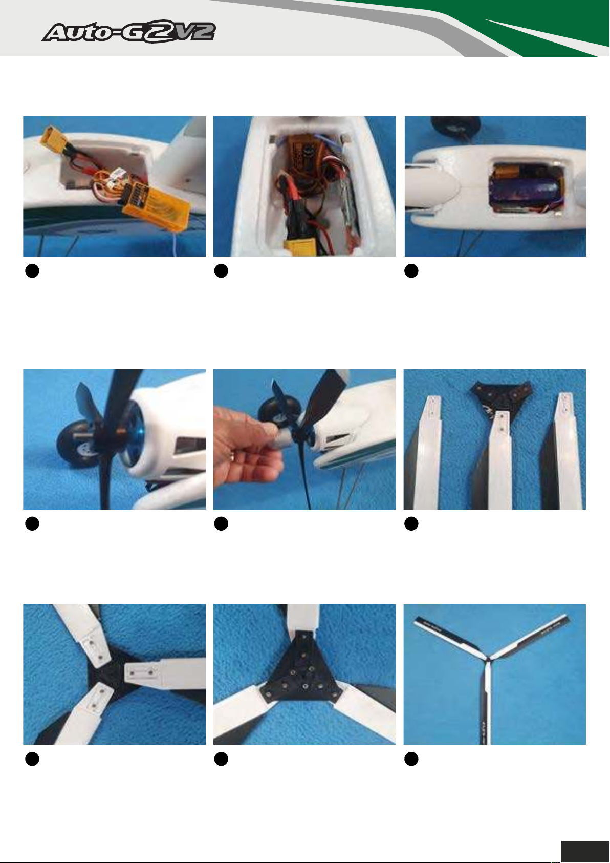
17
At this point it is best to install
your receiver to set up your radio
and the servos. Don't forget to
check the direction of the motor.
See further on in this manual for
the control throws.
18
Most small receivers should
sit nicely at the rear of the battery
compartment, just in front of the
servos. Use some doublesided
tape to fix the auto-start controller
to the side of the compartment.
19
Position your 1300mAh 3S as
shown in the battery compartment.
Please note: The auto-start system
has a built-in safety device, and will
not start when the battery is
connected, regardless of the switch
position.
20
3 Check that the hex-nut on the
motor shaft is wound down to the
end of the thread, slide the prop
on and locate the backplate of the
prop over the nut.
23
3 View of the finished assembly
center hub looking from the top.
213 Thread the spinner onto the
shaft and tighten fully by hand.
Note: The prop should be balanced,
but it is always advisable to check
the balance before fitting.
24
3 View of the finished assembly
looking from underneath. Note that
the angled end of the nut plates
match the triangular molding in the
middle.
22
The next step is to assemble the
main rotor. The rotor blades are
supplied with one blade attached to
the rotor hub as a pattern on how to
attach the other two.
25
View of the completed assembly
from the top. Note that the blades
have a negative incidence.
5
Page 9
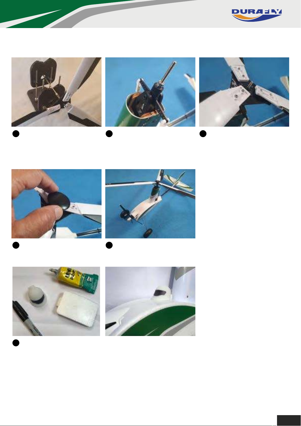
26
We highly recommend that
you balance the rotor-head as
shown with a good quality prop
balancer.
27
Before you fit the rotors, check
that the 2 nuts at the top of
the shaft are locked together.
28
Slide the rotor-head center plate
onto the main shaft until it touches
the two lock-nuts, rotor blades must
be on the top of the center-plate.
29
3 Screw the head button into
place to hold the rotor-head on.
30
3 The Auto-G2 V2 comes with a 3D printed pilots head for gluing to the
30
3 The basic assembly of your
Auto-G2 V2 is almost there.
battery hatch. This can be either painted, or colored in with marker pens.
6
Page 10
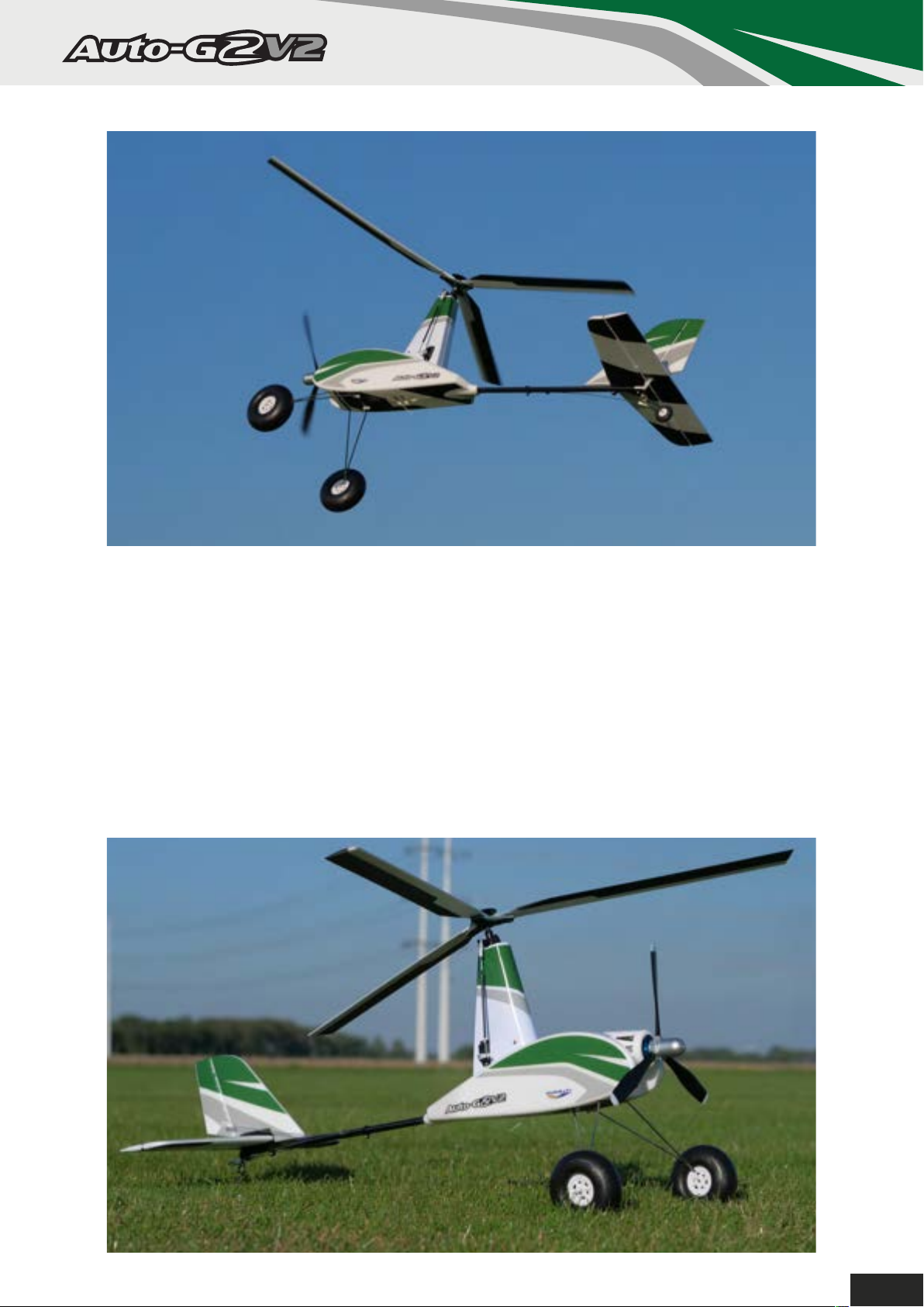
Congratulations, assembly of your
Auto-G2 V2 is now complete.
Please perform a final check of all the screws, nuts,
bolts and components, ensuring they are secure
and firmly in place.
7
Page 11
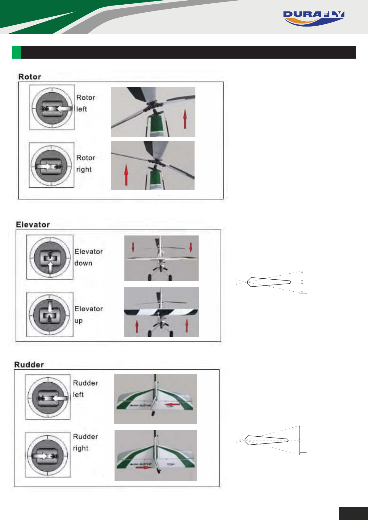
SETTING UP THE AUTO-G2 V2:
6(77,1*837+($872*9
&21752/7+52:6
5ROO$LOHURQ&RQWUROV
5DWHV([SR
1RUPDOIO\LQJUDWHV
H[SR
,QLWLDO)OLJKWVUDWHV
H[SR
CONTROL THROWS
Roll/Aileron Controls (Rates/Expo)
Normal flying: 75% rates, 25% expo
Initial Flights: 100% rates, 30% expo
Elevator:
10mm low, 14mm high
10 - 14mm
10 - 14mm
Rudder:
12mm low, 20mm high
12 - 20mm
12 - 20mm
8
Page 12
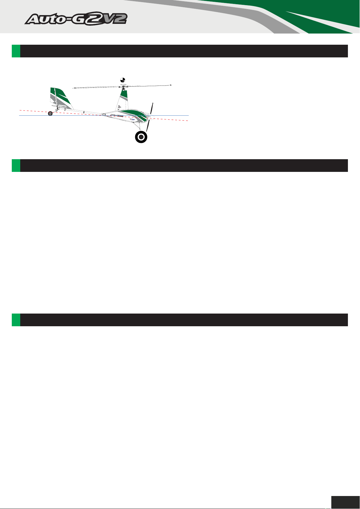
CG LOCATION:
With the recommended battery installed, lift the
AutoG2 V2 by the head and the nose should
drop to approximately 3-5 degree’s below the
horizon. This indicates you are within the
3-5°
Horizontal line
correct CG range. Add weight to the nose or tail
until you find a balance point you are
comfortable with within this range when flying.
MODEL FLYING PRECAUTIONS:
• Select your flying area carefully, always choose an open space that is free from obstructions and away from
crowded areas. Avoid flying in areas with roads, electric/telephone poles/wires, or within close proximity to
full size air traffic.
• Do not fly this model in poor weather, high winds, fog or mist, inclement temperatures, and rain and storms
are to be avoided.
• Never attempt to catch this model whilst in flight. Even a slow moving model can cause harm to yourself and
others, and risks damage to the model.
• This model is recommended for children no younger than 14 years old. All children, no matter what age,
should always be supervised by a capable and responsible adult when operating this model.
• Remember to keep clear of the propeller at all times when the flight battery is connected.
• Before flying, always turn on your transmitter first, then plug your flight battery into the model.
• After flying, always unplug your flight battery first, then turn off your radio transmitter. Never leave the battery
plugged in when not in use.
• Exercise caution when charging your battery, follow in full the manufacturers safety and charging guidlines.
PRE-FLIGHT CHECKS:
1. Always range check your model before any flight (especially when flying a new model for the first time).
Follow your radio manufacturers guidelines for performing this check.
2. Check all screw bolts and mounting points are firmly secure, including control horns and clevises. Also
check that the rotor head is secure and installed correctly (not upside down).
3. Only fly with fully charged batteries (both in your radio and model). Failure to do so could result in loss of
control, damage to the model and/or persons/property around you. Check your batteries are fully charged.
4. With the model powered up (transmitter on first, then receiver/model) check that all surfaces are free from
damage/obstructions, moving in the correct directions and freely with the stick inputs.
5. Inspect the model, prop and rotors for any damage that may have occurred during transit and listen for any
unusual sounds from the electronics when powered up. If in doubt, do not fly.
6. With the model held securely and the prop free of obstructions, increase the throttle just slightly to confirm
the rotation of the prop is correct. The model should want to pull straight forward with throttle.
9
Page 13

HINTS AND TIPS ON FLYING THE AUTO-G2 V2:
First, just a little insight into the differences between flying an autogyro and a conventional fixed-wing airplane.
Autogyros are often regarded as "unstable" by fixed-wing airplane pilots, this is certainly true if you try to fly an
autogyro using fixed-wing principles. Flown properly, an autogyro is actually safer and easier than flying a fixed-wing
airplane as it is unable to stall. A fixed-wing will stall if it is flown too slowly for the wing to produce lift, since the rotor
of an autogyro is always spinning, it simply cannot stall. If the forward airspeed becomes zero, the autogyro will slowly
drift to the ground rotors still spinning. Ok, a vertical landing in this manner will not be a smooth affair, but it should not
damage the model.
The one weakness they do have is that they can lose rotor control authority if you subject the rotor to negative-G
forces such as pushing the elevator stick forward (like going over a hump back bridge). Remember that a flying
autogyro hangs from the rotor much like an object hanging on a piece of string. As long as the autogyro is hanging
from the rotor, stability is maintained. The instant zero or negative-G is introduced, the rotor speed begins to decay
and stability is lost. If this situation occurs whilst flying then ease back on the elevator, this increases the angle of
attack causing the airflow to pass back up through the rotors allowing them to spin back up to speed and resume
stability. This is why in normal flight the rotors are angled backwards, this causes the airflow to pass up through the
rotors from underneath to keep them spinning at speed. Now you understand a little more about the differences in
flying your Auto-G2 V2 you should be ready for your first flights.
Set your rates to high and start with a bit of taxiing around to get used to the ground handling, make sure you hold in
full up elevator while taxiing. With the big bush-style wheels and wider, sturdier landing gear, you will notice that
taxiing around is much better with the Auto-G2 V2 than earlier versions of this model.
Once lined up for take-off into wind, hold a little bit of right roll (ailerons), as it will try to roll a little to the left as you
accelerate to lift-off, also hold in some up elevator. Flick the auto-start switch and wait for the rotors to spin up to
full-speed, once at full-speed gently open the throttle and keep the model straight using rudder. Ease of the elevator
as the speed increases and as the tail lifts up your Auto-G2 V2 should lift smoothly into the air and steadily climb-out,
you will most probably not be anywhere near full throttle to achieve a nice smooth climb-out. Switch the auto-start off
at this point and keep steadily climbing, then try a banked turn left of right to bring the model back towards the take-off
area. You will find when turning you will need to use the rudder a lot more than the roll control, this is something bank
and yank pilots will have to get used to, this method does not work with the Auto-G2 V2 or any autogyro for that
matter. If you have flown helicopters, or large scale models, you will be well used to this style of flying and
coordinating your turns using roll (ailerons), and rudder. Be careful not to fly too far away, as orientation with this style
of model is more difficult than with conventional fixed-wing airplanes.
Once at a safe height, throttle back a little and get used to the delightful flying characteristics of your Auto-G2 V2.
Once you are settled and getting familiar with the handling turn it into wind and slow it down by easing back on the
elevator and using the power to control the height. You will find that it will almost hover by using quite a lot of up
elevator, and quite a bit of power. We do not recommend that you aerobat the Auto-G2 V2, but it will do very nice stall
turns. Just remember that once you have completed the stall turn at the top of the maneuver, you will need to throttle
back ease back more on the elevator as the nose drops to slow the model down, this will keep the rotors spinning
nicely and not allow the model to over-speed.
By now you should be ready to attempt a landing approach, as normal, fly a nice left or right hand circuit and set
yourself up on the final approach to the landing area. Initially, just treat it the same as any fixed-wing airplane and fly it
down the approach using elevator and throttle control to achieve a steady descent. Once near the ground just round
out gently as normal, and with a bit of power still on gently flare, you don't need too much elevator to achieve a nice
3-point landing. Once you have flown the Auto-G2 V2 a few times, you will find you can really slow it up on landing
using lots of elevator and quite a bit of power, and land with very little forward speed for super short landings.
We hope you enjoyed your first flight with your Auto-G2 V2, and have many more enjoyable flights in the future.
Don't forget to watch our flying demo video: https://www.youtube.com/watch?v=aNTVGCxbk3w
Have fun, and happy flying.
The Durafly team.
10
Page 14
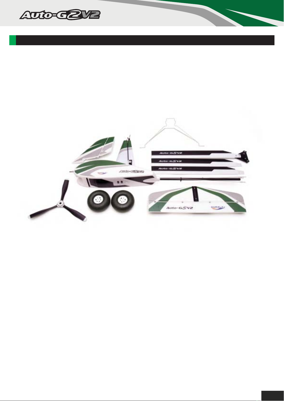
AUTO-G2 V2 SPARE PARTS LIST:
FULL RANGE OF SPARES
COMING SOON!
11
Page 15
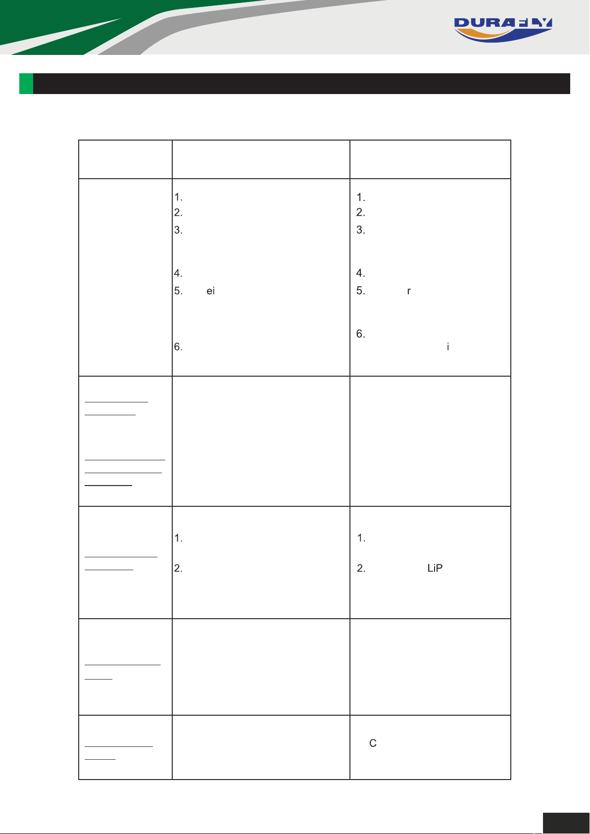
TROUBLE SHOOTING:
Problem Cause Solution
Motor does
not turn
Model moves
backwards
Control surfaces
not moving with
stick input
Battery is not fully charged.
Transmitter battery low.
Motors not connected.
The motor is damaged.
Rec ver is not bound to
Tx.
ESC in set-up mode.
1. Prop installed backwards
2. Motor direction reversed
1. The servo lead is connected
to Rx incorrectly.
2. The servo is damaged.
Charge the batteries.
Install a full charged battery.
Check for connection
between the ESC and
motor.
Replace motor.
Consult adio manual and
go through bind procedure
again.
Hold model and move
throttle to full pos tion then
back down to idle.
.dnuora porp eht nruT.1
2. Disconnect any two motor
wires from ESC, swap
around and reconnect.
1. Make sure the servo leads
are connect properly.
2. Replace servo.
Model does not
fly straight
Model does not
climb
Limited Radio
Range
Control surfaces not centered.
CG is not in the correct position.
1. The battery is not fully charged.
2. Elevator servo is reversed.
3. CG too far backwards.
1. Transmitter/ Receiver batteries
are flat.
Adjust the trims on the
transmitter.
Re-position o as
suggested.
1. Charge the battery.
2. Change servo direction
via Tx.
3. Move battery forwards.
1. harge/replace batteries.
12
Page 16
CONTACTS:
Notes:
13
Page 17

Made in China
 Loading...