

Page 1
1!of!4! September!12,!2014
!
!
BMS$360$48*
48$Volt*Battery*Management*System*
Owners*Guide*
(These instructions are intended for use by a technician familiar with electronic products)
• 2!Rack!unit!high!
• Up!to!40!Amps!max!load!
• Suggested!battery!capacity:!20!to!65!AH!
• Smart!Charging!and!Low!Voltage!Disconnect!
• Front!panel!indicators!for!AC!fail!
• 3!year!warranty
DESCRIPTION
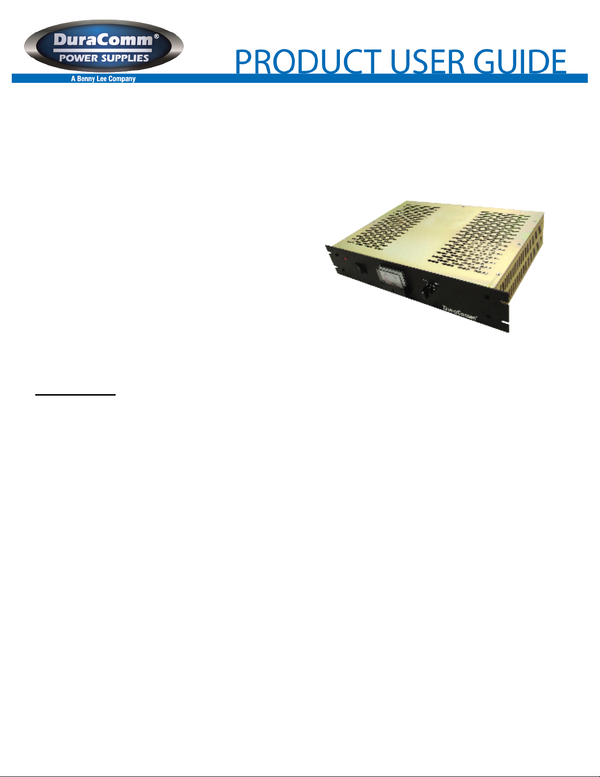
The Model BMS-360-48 is a complete battery management system for installations which already have a primary power
supply but are lacking battery backup. Smart Charging and battery protecting Low Voltage Disconnect maintain and prevent battery
failures caused by over-charging and excessively deep discharging. Dual Schottky diodes provide smooth transfer to battery power and
auto-revert to AC mains power that is seamless and glitch less.
The Smart Charger is designed to auto-charge and maintains Gelled electrolyte (Gel-Cell) and liquid electrolyte lead-acid 48
volt batteries up to 65 Amp Hour. The charger is a constant current monitoring charger for the charging and maintenance of fixed
location UPS, emergency lighting systems, and telecommunications battery backup systems.
The charger is protected against over loading by deep discharge start circuitry with auto shut down due to over-voltage, overtemperature, short circuit and reverse polarity.
Switching mode circuit design provides high efficiency, compact size, cool operation, and high reliability.
The Model BMS-360-48 incorporates an automatic Low Voltage Disconnect that monitors battery voltage and disconnects the
load when the battery voltage drops below 42 VDC. The LVD has been adjusted and calibrated at the factory for correct voltage
disconnect and re-connect. No adjustment is required.
The LVD is pre-set to disconnect the load at 42 VDC. However, to prevent premature or false disconnect when the battery
voltage drops below the 42 volt threshold a timer is started. If the battery recovers to above 42 volts, the timer resets and waits. The
battery can and will recover if the system is a repeater or remote base station or similar equipment that has a varying demand that
fluctuates from low to high current. The delay ensures the battery is not disconnected until necessary to prevent damage.
After the AC main power is restored and the battery is recharging, the LVD will reconnect the load when the battery voltage
exceeds 50 volts.
Page 2

2!of!4! September!12,!2014
SPECIFICATIONS
Operational DC Voltage…………………………………………………………………………………………..55.2 VDC, nominal
Maximum Current, continuous……………………………………………………………………………………………….40 Amps
Low Voltage Disconnect……………………………………………………………………………………………………... 42 VDC
Low Voltage RE-Connect………………………………………………………………………………………………………50 VDC
Maximum Charger output current……………………………………………………………………………………………6.2 Amps
AC Input voltage range (switch selectable, Factory Set)……………………………………………….100-130 or 200-260 VAC
Max inrush current, single cycle…………………………………………………………………………………………………..60 A
Input frequency range…………………………………………………………………………………………………………47-63 Hz
Typical Efficiency…………………………………………………………………………………………………………….……85 %
Short Circuit protection………………………………………………………………………………………..……Fold back Limiting
Overload Protection (operates)………………………………………………………………………………………..typical 110 %
Over Temperature……………………………………………………………………………..>195 F (90 C) auto output shutdown
Working Temperature range…………………………………………………………………………………-4 –140 F (-20 - +60 C)
Storage Temperature………………………………………………………………………………………-40 – 185 F (-40 - +85 C)
Size………………………………………………………………………………………...3.5” in (Two rack units) h x 19” w x 13” d!
Weight…………………………………………………………………………………………………………………..12.5 lb, nominal
CHARGER SPECIFICATIONS
Output Voltage, charger……………………………………………………………………………………………………..55.2 VDC
Maximum Charger Power, continuous…………………………………………………………………………………….360 Watts
Maximum Charger output current……………………………………………………………………………………………6.2 Amps
Max inrush current, single cycle………………………………………………………………………………………………60 Amps
AC Input voltage range (switch selectable)…………………………………………………….…………90-130 or 180-260 VAC
Input frequency range………………………………………………………………………………………………………..47-63 Hz
Typical Efficiency……………………………………………………………………………………………………..………….85 %
Short circuit protection………………………………………………………………………………………….....Fold back Limiting
Overload Protection (operates)…………………………………………………………………………………………Typical 110%
Over Temperature range…………………………………………………………..…………>195 F (90 C) auto output shutdown
Working Temperature range…………………………………………………………………………………-4 –140 F (-20 - +60 C)
Storage Temperature………………………………………………………………………………………-40 – 185 F (-40 - +85 C)
INSTALLATION WARNING
The individual user should take care to determine, prior to use or installation, whether this device is suitable, adequate or safe for the
use intended. Since individual applications are subject to great variation, DuraComm makers no representation or warranty as to the
merchantability, suitability or fitness of these units for any specific application.
DO NOT block any of the cooling vents on the sides and always allow adequate ventilation by not installing the unit inside tightly closed
spaces. Physical mounting position is not critical but the cooling vents must not be blocked. Make certain the input voltage switch is
set to the correct voltage BEFORE applying AC power.
The power supply output voltage measured at the rear panel terminals should be set to 56 VDC using an accurate voltmeter.
This is to compensate for the 0.3 volt drop of the diode switches. If this voltage is not correct, charger mis-operation will
result.
Connect the battery positive to the red terminal labeled, “Battery Positive (+)”.
Connect the load positive to the red terminal labeled, “Load Positive (+)”.
Connect the power supply positive output to the red terminal labeled, “Power Supply Positive (+)”.
Connect the power supply, battery and load negative outputs to the black terminal labeled, “Power Supply, Load, Battery Negative (-).
Page 3

3!of!4! September!12,!2014
CAUTION: Under no circumstances should more than 60 VDC be applied to the input. Permanent damage to the LVD
will result.
Make certain the unit is OFF. Double check the color coded leads from the battery, load and power supply. Select the proper AC input
voltage, 110-120 VAC or 220-240 VAC, prior to plugging the unit into the AC mains.
L.E.D. STATUS INDICATORS - There is one LED type status light located on the BMS unit.
When charging series connected batteries identical batteries must be used.
This completes the installation. Failures require investigation as to cause and/or repair of the unit.
THERE ARE NO USER SERVICEABLE PARTS INSIDE. SERVICE AND REPAIR MUST BE REFERRED TO QUALIFIED
FACTORY PERSONNEL.
INSTALLER NOTES
WARNING: THERE ARE NO USER SERVICEABLE PARTS INSIDE. SERVICE AND REPAIR MUST BE REFERRED TO
QUALIFIED FACTORY PERSONNEL.
NOTE: The individual user should take care to determine, prior to use or installation, whether this device is suitable, adequate or safe
for the use intended. Since individual applications are subject to great variation, DuraComm makes no representation or warranty as to
the merchantability, suitability or fitness of these units for any specific application.
RECOMMENDED COPPER WIRE SIZE FOR CURRENT CAPACITY
(Insulated Wire, Single Conductor in free air)
Current Level in Amperes
<7 AMPERES
Wire Size
20 AWG Up to 5 feet
18 AWG Up to 10 feet
14 AMPERES
18 AWG Up to 5 feet
16 AWG Up to 10 feet
20 AMPERES
16 AWG Up to 5 feet
14 AWG Up to 10 feet
30 AMPERES
14 AWG Up to 5 feet
12 AWG Up to 10 feet
40 AMPERES
12 AWG Up to 5 feet
10 AWG Up to 10 feet
50 AMPERES
10 AWG Up to 5 feet
8 AWG Up to 10 feet
70 AMPERES
8 AWG Up to 5 feet
6 AWG Up to 10 feet
100 AMPERES
6 AWG Up to 5 feet
4 AWG Up to 10 feet
!
Page 4

4!of!4! September!12,!2014
LIMITED WARRANTY
DuraComm warrants to the initial end user, each power supply manufactured by DuraComm to be free from defects in
material and workmanship, when in normal use and service for a period of three year from the date of purchase, from an
authorized DuraComm dealer.
Should a product manufactured by DuraComm fail or malfunction due to manufacturing defect, or faulty component,
DuraComm, at its option, will repair or replace the faulty product or parts thereof, which, after examination by
DuraComm, prove to be defective or not operational according to specifications in effect at the time of sale to the initial
end user. The product that is replaced or repaired under the provisions of this warranty, will be warranted for the
remainder of the original warranty period, only, and will not extend into a new three year warranty period.
The limited warranty does not extend to any DuraComm product which has been subject to misuse, accidental damage,
neglect, incorrect wiring not associated with manufacture, improper charging voltages, or any product which has had the
serial number removed, altered, defaced, or changed in any way.
DuraComm reserves the right to change, alter, or improve the specifications of its products at any time, and by so doing,
incurs no obligation to install or retrofit any such changes or improvements in or on products manufactured prior to
inclusion of such changes.
DuraComm requires any product needing in or out of warranty service to be returned to DuraComm. All requests for
warranty service must be accompanied by proof of purchase, such as bill of sale with purchase date identified. DuraComm
is not responsible for any expenses or payments incurred for the removal of the product from its place of use,
transportation or shipping expenses to the place of repair, or return expenses of a repaired or replacement product to its
place of use.
The implied warranties which the law imposes on the sale of this product are expressly LIMITED, in duration, to the three
(3) year time period specified herein. DuraComm will not be liable for damages, consequential or otherwise, resulting from
the use and operation of this product, or from the breach of this LIMITED WARRANTY.
Some states do not allow limitations on the duration of the implied warranty or exclusions or limitations of incidental or
consequential damages, so said limitations or exclusions may not apply to you. This warranty gives you specific legal
rights which vary from state to state.
This warranty is given in lieu of all other warranties, whether expressed, implied, or by law. All other warranties,
including WITHOUT LIMITATION, warranties of merchantability and fitness or suitability for a particular purpose, are
specifically excluded. DuraComm reserves the right to change or modify its warranty and service programs without prior
notice.
DuraComm® Corporation
6655 Troost Avenue
Kansas City, MO 64131
Phone (816) 472-5544 Fax (816) 472-0959
www.duracomm.com
 Loading...