

Page 1
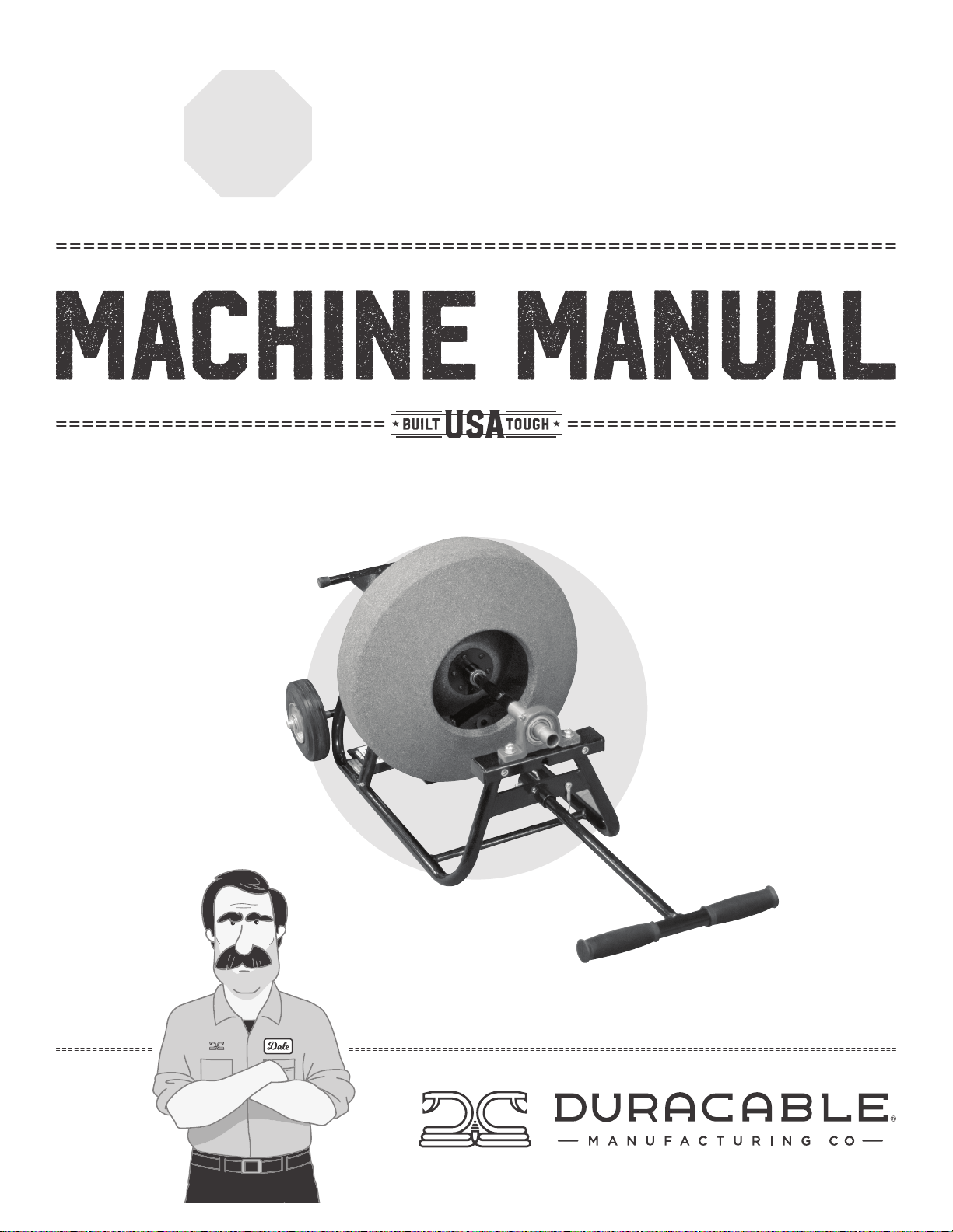
Read manual before operating
stop
keep manual for future reference
j-maxx
Right in there with you.
Page 2
J-MAXX MACHINE MANUAL
Table of Contents
2 Warranty, Parts and Service
3 Safety Labels
4-7 J-Maxx Information and Specifications
8-9 J-Maxx Machine Schematics and Parts List
10 J-Maxx Reel Schematics and Parts List
11-12 Mini Power Cable Feed and Return Schematics and Parts List
13-14 J-Maxx Electrical Schematics and Safety Information
15 How to Splice DuraFlex® Cable and How to Bond End Fittings
WARRANTY
Duracable Manufacturing Company warrants the J-Maxx machine to be free from defects in material and workmanship for a period of two years
from the date of purchase. Warranty service can be obtained by contacting Duracable Manufacturing Company at the address listed below. If a defect
is covered by warranty, Duracable Manufacturing Company will repair or replace the defective machine or component without charge for labor or
materials (freight is not included).
Warranty of the machine is limited to the original purchaser. Duracable Manufacturing Company assumes no responsibility for damage or injury from
accident, neglect, abuse, misuse or from damage due to repair or alterations by others. This warranty does not cover damage to the machine from use
of parts other than genuine Duracable brand parts.
Duracable Manufacturing Company’s sole obligation and the original purchaser’s sole remedy under this warranty shall be for repair or replacement
as described above. All other warranties, expressed or implied, including but not limited to, implied warranties of merchantability and fitness for a
particular purpose, are disclaimed. In no event shall Duracable Manufacturing Company be liable for any incidental or consequential damages.
PARTS AND SERVICE INSTRUCTIONS
Parts can be purchased from Duracable Manufacturing Company. Service work is also available. Service is performed by trained factory personnel.
Machines sent to the factory for evaluation and repair can be estimated and quoted prior to service work. When sending a machine, be sure to include
the return address and include instructions on how the repair should be handled. Instructions can either be included with the machine, explained to your
account manager over the phone (800-247-4081), or faxed (515-223-6109).
IMPORTANT
Keep this manual in a safe, convenient place for future reference. Important information about this machine, its diagrams and warranty information are
included in this manual.
Serial Number: Date of Purchase:
Duracable Manufacturing Company
300 Ashworth Road • West Des Moines, IA 50265
2
Page 3
Safety Labels
J-MAXX MACHINE MANUAL
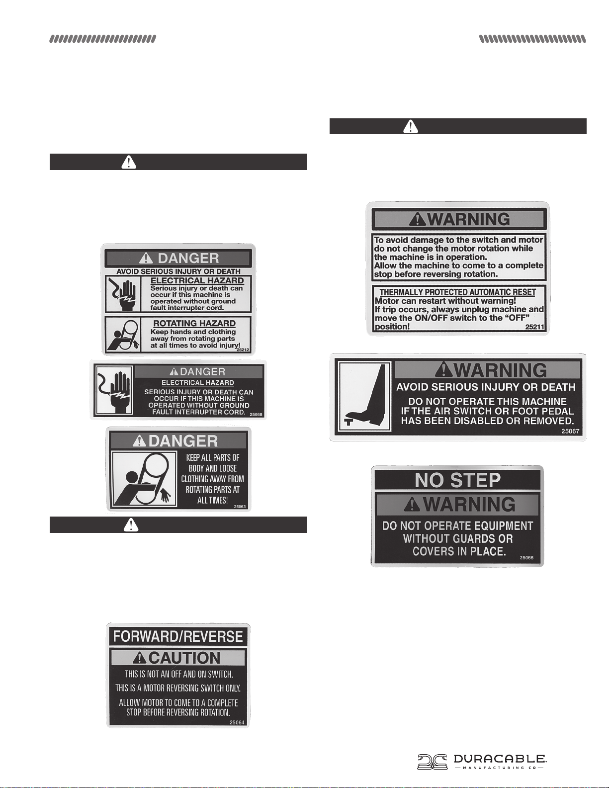
Duracable Manufacturing uses three signal words on its
safety labels and instructions. These words have the following
definitions:
DANGER
A ‘Danger’ label indicates an imminently hazardous situation
that, if not avoided, will result in death or serious injury. This
signal word is to be limited to the most extreme situation,
typically for machine components that, for functional purposes,
cannot be guarded. The word ‘danger’ will be in white letters on
a red background.
WARNING
A ‘Warning’ label indicates a potentially hazardous situation
that, if not avoided, could result in death or serious injury, and
includes hazards that are exposed when guards are removed.
It may also be used to alert against unsafe practices. The word
‘warning’ will be in black letters on an orange background.
CAUTION
A ‘Caution’ label indicates a potentially hazardous situation that,
if not avoided, may result in minor or moderate injury. It may also
be used to alert against unsafe practices. The word ‘caution’ will
be in black letters on a yellow background.
The safety label format includes the signal word and symbol, a
picture (not required), and the message.
3
Page 4
J-MAXX MACHINE MANUAL
Information and Specifications
Safe Machine Operation
Read this machine manual thoroughly before assembling or
operating the machine. Become familiar with its controls and
proper use before operating. Keep this manual in a handy place
for reference and parts replacement referral. This machine is
designed specifically for the purpose of opening and cleaning
drains. Use it for this purpose - do not use it for other purposes.
Use gloves to protect your hands. Wear them to feed and
retrieve cable. Use a material that cannot be easily grabbed by
the cable. Most leather gloves and certain rubber gloves work
well. Duracable Manufacturing has each type available through
the Duracable Product Catalog. Also, avoid the use of loosefitting clothes or jewelry when operating this machine.
Keep guards in place to protect the operator from the electric
motor and electrical wiring. These guards are for safety
protection and must be in place when running the machine.
Each machine is equipped with an air foot pedal. Use of the air
foot pedal to operate the machine is required for safe operation.
This allows the machine operator to turn the machine on or o
with the foot while keeping both hands on the cable.
Select a work area free from obstruction with room to work.
Keep the machine within three feet of the pipe opening, allowing
only enough room to work. This is required to shorten the length
of exposed cable, thus providing maximum control in hightorque situations. Take a position that is comfortable to the left
or right side of the machine for feeding or retrieving cable. For
high work openings, the machine can be placed on its back as
conditions require.
When performing a job, use the smallest blade first. Rinse the
pipe after each blade is run through the line in order to clean out
loosened debris. Then follow with the increasing sizes of blades
until the size used is one that actually scrapes the side of the
pipe or sewer. The blades are flexible and can be compressed
to enter most cleanout openings. Centrifugal force created by
the spinning cable forces the blades to expand to their natural
diameter or to the walls of the pipe. It is advisable to maintain a
very keen cutting edge on the blades at all times.
Place two hands on the cable between the outlet of your
machine and the cleanout, and keep them there at all times
during operation. Your hands placed in the proper position, will
provide a guide for the cable. Keep the machine within three feet
of the pipe opening.
As the blade makes contact with an obstruction in the line, it
stops the blade from turning and builds torque in the cable.
Do not permit the blade to get hung up in an obstruction for
more than three seconds. Torque buildup can be both helpful
and dangerous. It is helpful when pulled from the obstruction
in a timely manner. When the cable is pulled away, the tension is
released and the blade turns at a high speed. When the blade is
free, feed it back into the obstruction to make use of the built-up
power to clean the line. It is dangerous because excess torque
can cause looping over of the cable. Serious injury to fingers
and hands is possible unless precautions are observed. When
retrieving cable from the line, feed the cable into the machine
until the blade is close to the cleanout opening. Shut o the
machine and hand-feed the remaining cable into the machine.
Unpacking Your Machine
The J-Maxx is shipped to you with the following parts: the base
machine, a drum, and a revolving arm. When it arrives, remove
the parts immediately and inspect for damage. If any of the
contents are damaged, contact your motor freight carrier
immediately.
Moving Your Machine
Break the machine down into lighter-weight components to
move it to and from the job site. To do this, wrap the GFCI cord
and the air foot pedal cord in a convenient spot on the machine,
remove the revolving arm from its assembled position (leave the
cable inside it and keep it with the drum), and remove the drum
assembly. Various accessories are available from Duracable
Manufacturing to assist and protect the operator during the
moving process.
Assembling Your Machine
• Attach the D3L Drum Attachment to the male end on one end
of the cable. Position the cable end with attachment inside the
cable and snap into place. Feed the cable into the drum.
• Set the base machine in a down position on its rails.
• Pick up the drum, loaded with cable, with the cone shape to
the front of the machine (toward the switches) and slide it
onto the drum shaft. Be sure the orange drive lugs slide into
the openings in the back of the drum and engage fully.
• Feed the cable through the revolving arm until it is flush with
the end of the arm.
• Position the revolving arm inside the drum.
• Position the extension shaft on the revolving arm into the
center of the drum bearing.
• Place the revolving arm with cable extended into the rear side
of the head bearing.
• Slide the collar forward using an Allen Wrench to loosen and
tighten the collar.
• Slide the cable through the head bearing.
Disassembling Your Machine
To disassemble the J-Maxx machine, reverse the assembly
process.
4
Page 5
J-MAXX MACHINE MANUAL
Information and Specifications
Lubrication Maintenance
Caution: Do not over oil these points.
• Head Bearing Assembly - The roller bearing, located in the
front assembly, requires monthly lubrication. Use a grease
gun to lubricate the zerk fitting with multipurpose grease. A
lithium-base grease is recommended.
• Drum Shaft and Drum Bearings - The drum shaft requires
monthly lubrication. Use a multipurpose grease or heavy oil.
Keeping the shaft lubricated means the drum will slide and
will not ‘freeze’ to the shaft and need to be repaired. The drum
bearings require some light oil monthly.
• Belt - Check tension during the first 24 to 48 hours of operation.
• Belt Tension - Ideal deflection is 1/4”. Over tensioning shortens
belt and bearing life.
• Air Foot Pedal - Check for wear or stress cracks.
j-Maxx
1/3 HP Motor
Cable Care Instructions
Take care of your cable for optimum performance. The
recommended care procedure is as follows:
• Break in a new cable. To relieve the stress on new cable that
has been coiled since its manufacture, put it in a clean line and
run it for 10 minutes.
• Oil the cable once a week.
• Rinse the cable immediately after each use with the hottest
water available. This is especially important if the cable was in
acid or alkali during use.
• When one end of the cable begins to show wear, rewind and
use the opposite end. (Tip: order the same kind of end fittings
on both ends of the cable.)
• If the cable kinks, cut out the kink and splice the cable ends
together.
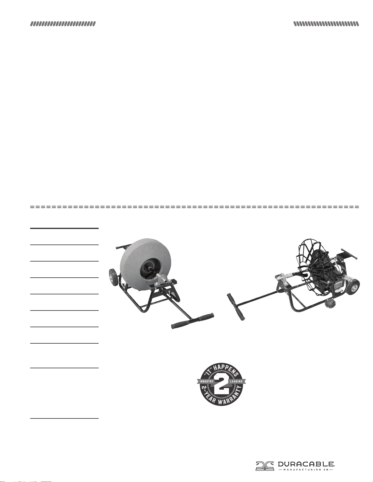
200 RPM
Belt Drive
19” Reel
1/2” x 75’ Cable
Detachable “T” Handle
2-Year Warranty
Continuous Weld
Uni-body Frame
USES:
1-1/4” to 3” lines,
Residential, Sinks,
Roof Vents,
Floor Drains
The J-Maxx with 16PRS, 16” enclosed polyethylene reel The J-Maxx with D1S1, 19” open spoke reel (standard package)
5
Page 6
J-MAXX MACHINE MANUAL
Information and Specifications
Frame
The J-Maxx’s frame consists of a uni-body construction
which allows the motor, head bearing and reel shaft
assemblies to be bolted directly to the frame.
Electrical Wiring
The J-Maxx’s electrical wiring is located in the conduit box
on the right side of the motor, housing both the forward/
reverse switch and the air foot switch. The Ground Fault
Circuit Interrupter (GFCI) is built into the electrical cord
for added safety. The air foot pedal is standard equipment
on The J-Maxx. This switch allows operators to turn the
machine on and o with their foot while their hands stay
on the cable.
RPM/Drive
The J-Maxx has a 1/3 HP motor and operates at 200 rpm.
The heavy-duty, self-aligning head bearing for The J-Maxx
has a cast housing which reduces stress and prevents
premature wear.
Maneuverability
The J-Maxx has optional 6” wheels and a detachable “T”
handle.
Cable and Reel Selections
The J-Maxx was designed to handle several reel sizes. The
reel selected is set in place and slipped onto the reel shaft.
Drive lugs are mounted on the drive plate and slip through
the openings in the back of the reel. The reel is held in
place by the revolving arm.
Standard Package
The J-Maxx’s standard package (part number J-Maxx SPA)
comes with the following items: revolving arm, 1/3 HP
motor at 200 rpm, 19” open metal spoke reel, 1/2” x 75’
cable, reel attachment, and choice of cable end fittings.
(Wheels and handle are not standard.) See the machine
packages and accessories chart on the next page for
additional options.
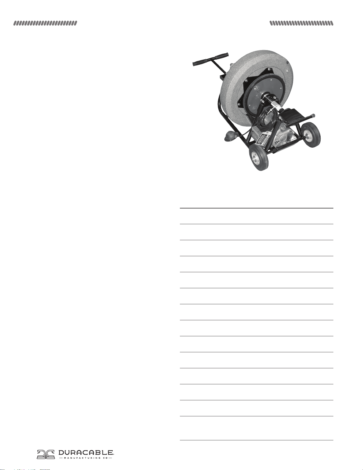
The J-Maxx shown above with 19PRS, 19” polyethylene reel.
(See options on the next page.)
Machine Specifications (Approximate)
Length of Machine 26”
Length of Machine with Wheels and Handle 44”
Width of Machine 13”
Width of Machine with Wheels and Handle 17.5”
Height of Machine 17”
Weight of Machine 44.5 lbs
Weight of Machine with Wheels and Handle 56.5 lbs
Weight of Narrow Wheels 13 lbs
Weight of D1S, 16” Open Spoke Metal Reel 9.5 lbs
Weight of 16PRS, 16” Polyethylene Reel 10.9 lbs
6
Weight of D1S1, 19” Open Spoke Metal Reel 10.5 lbs
Weight of 19PRS, 19” Polyethylene Reel 12.4 lbs
Line Size 1-1/4”-4”
Recommended Use: residential lines, sinks,
bathtubs, shower drains, roof vents and laundry drains
Page 7
J-MAXX MACHINE MANUAL
Information and Specifications
Reel
Reels
Part # Dimensions Description Part # Part # Part # Part # Part # Dimensions
D1S 16” Diameter Open Spoke Metal Reel D3L D2JS D3E D8SL2A with 31021
D1S1 19” Diameter Open Spoke Metal Reel
(standard)
D1SE 16” Diameter Enclosed Metal Reel D3S D2JS D3E D8SL2A with 31021
D1S1E 19” Diameter Enclosed Metal Reel D3S D2JM
16PRS 16” Diameter Enclosed Poylethylene
Reel
D1S1E 19” Diameter Enclosed Poylethylene
Reel
* Add CH in front of cable part # for Hollow Core.
* Add CI in front of cable part # for Inner Core.
* Maximum length of cable is not always the recommended length.
* Custom lengths are available.
Attachments
D3L D2JM
N/A N/A N/A D8SL2A with 31021
N/A N/A N/A D8SL9A with 31020
floating
Rings
D2JR
D2JR
floating ring
attachments
D3E
D3R (male end)
D3RJ (slip joint)
D3E
D3R (male end)
D3RJ (slip joint)
Revolving Arm Cables*
Arm Extension
D8SL9A with 31020
Arm Extension
Arm Extension
D8SL9A with 31020
Arm Extension
Arm Extension
Arm Extension
__38-090
__50-075
__50-090
__62-080
__38-090
__50-075
__50-090
__62-080
__38-090
__50-075
__50-090
__62-080
3/8” up to 90’
1/2” up to 75’
1/2” up to 90’
5/8” up to 80’
3/8” up to 90’
1/2” up to 75’
1/2” up to 90’
5/8” up to 80’
3/8” up to 90’
1/2” up to 75’
1/2” up to 90’
5/8” up to 80’
Machine Packages
Part # Horse Power RPM Reel Cable
J-MAXX SP 1/3 HP Motor 200 RPM D1S 3/8” x 75’
J-MAXX SPA 1/3 HP Motor 200 RPM D1S1 1/2” x 75’
J-MAXX SPB 1/3 HP Motor 200 RPM 16PRS 3/8” x 75’
J-MAXX SPC 1/3 HP Motor 200 RPM 19PRS 1/2” x 75’
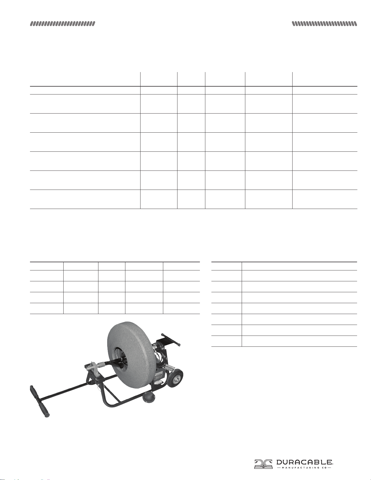
J-Maxx with 19PRS, 19” enclosed polyethylene reel
Machine Accessories / Replacement Parts
Part # Description
31005 1/3 HP Motor
25074 Air Foot Pedal (rubber) with 10’ Tubing
25061 Air Switch with Strain Relief Nut
DRC16 Cover for 16” Open Spoke Reel (D1S)
DRC19 Cover for 19” Open Spoke Reel (D1S1)
31001 Replacement Mobility Kit (wheels and handles)
DKIT1 Blade Kit
7
Page 8
J-MAXX MACHINE MANUAL
J-Maxx SchematiC
18
21
14
12
19
10
8
25 27
23
22
16
4
5
6
9
12
13
14
24
6
1
15
3
11
17
20
29
30
F
D
2
L
B
8
7
26 28
C
E
A
H
G
J
K
31
32
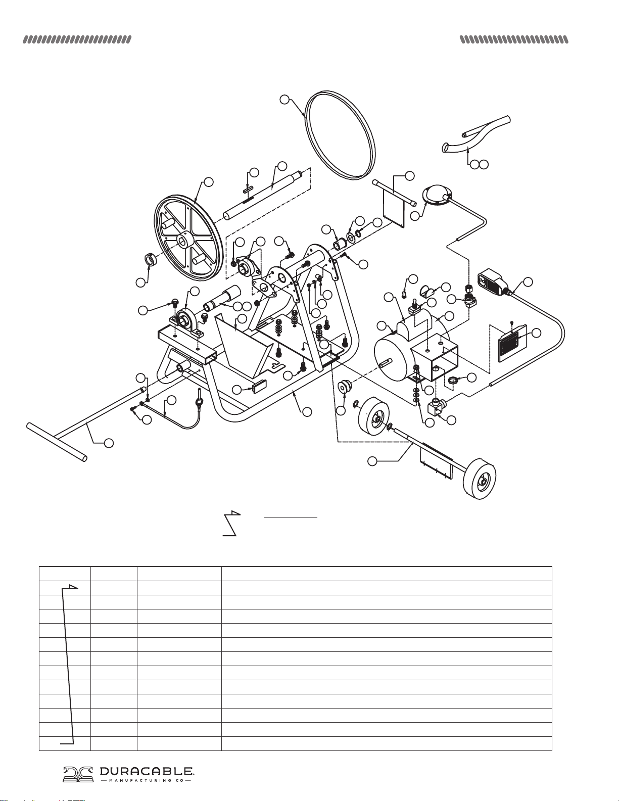
The entire line item in bold identifies the name of an entire assembly. The “Z” shaped
arrow identifies all the parts that make up that assembly. You can purchase the entire
assembly, or just the individual parts.
Item Qty. Part# Description
1 1 D31015 Frame, Red
2 1 31005 Motor Assembly
A 1 31005A Motor, 1/3 HP
B 1 25002 Switch, Detent - Forward/Reverse
C 1 25015 Switch Guard
D 1 ECT26 Rubber Switch Boot
E 2 25061 Air Foot On/O Switch with Nut
F 1 25074 Foot Pedal with 10’ Tube
G 1 ECT34 1/2” Strain Relief, 90° Snap Elbow with Dome Nut
H 1 ELN1 Electrical Nut, 1/2” NPT (National Pipe Thread)
J 1 25166 GFCI Cord, 16/3 x 22”
K 1 25064 Decal, Forward, Reverse Caution
L 1 25212 Decal, GFCI Rotating Danger
8
Page 9

J-MAXX MACHINE MANUAL
J-Maxx SchematiC
The entire line item in bold identifies the name of an entire assembly. The “Z” shaped
arrow identifies all the parts that make up that assembly. You can purchase the entire
assembly, or just the individual parts.
Item Qty. Part# Description
3 1 RRING14 External “E” Ring
4 1 WA32 Machine Bushing
5 1 SB19 Drum Shaft Bearing
6 6 FLSC1 5/16”-18 x 3/4” Hex Head Flange Screw
7 12 WA15 1/3” x 3/4” x .07” Stainless Steel Flat Washer
8 6 FLNUT3 5/16”-18 Hex Flange Nut, Locking
9 1 SB5 Bearing, Drum Shaft
10 1 31040 Drum Shaft
11 2 PHSC5 #10-32 x 1/2” Pan Head Thread Cutting Machine Screw
12 1 CCL1 Cable Clamp, Black
13 2 WA5 #10 External Tooth Lock Washer
14 1 HXNUT3 #10-24 Hex Nut
15 1 41010A Sheave, 4L x 1-1/2” Outside Dia
16 1 KEY6 1/4” x 1-3/8” Square Key
17 1 41010B Sheave, 4L x 11-1/4” Outside Dia with Drive Lugs
2 25090A Drive Lug
2 MM4 Drive Lug Cap, Red
2 WA10 3/8” Split Lock Washer
1 41008 Guard, Sheave
18 1 25120 Drum Shaft Bushing
19 1 41010C Belt, 4L x 37”
20 1 SB8 Head Bearing
21 2 FLSC7 3/8”-16 x 5/8” Hex Head Flange Screw
22 2 MM16 End Cap, Black
23 1 41009 Motor Guard
24 1 D25000 Decal, Machine Logo
25 1 31020 Revolving Arm Extension (D8SL9A revolving arm only)
26 1 D8SL9A Revolving Arm without Collar for 19” Reel
27 1 31021 Revolving Arm Extension (D8SL2A revolving arm only)
28 1 D8SL2A Revolving Arm without Collar for 16” Reel
29 1 JWKL Detent Ring with Attached Lanyard
1 31001 Mobility Kit
2 FLSC1 5/16-18x3/4 Hex Head Flange Screw
2 FLNUT3 5/16-18 Flange Lock Nut
30 1 31050 Vertical Support Assembly
31 1 31025 T-Handle with Grips
32 1 31045 Wheel Axle Assembly
9
Page 10
J-MAXX MACHINE MANUAL
5
4
3
1
2
7
6
8
9
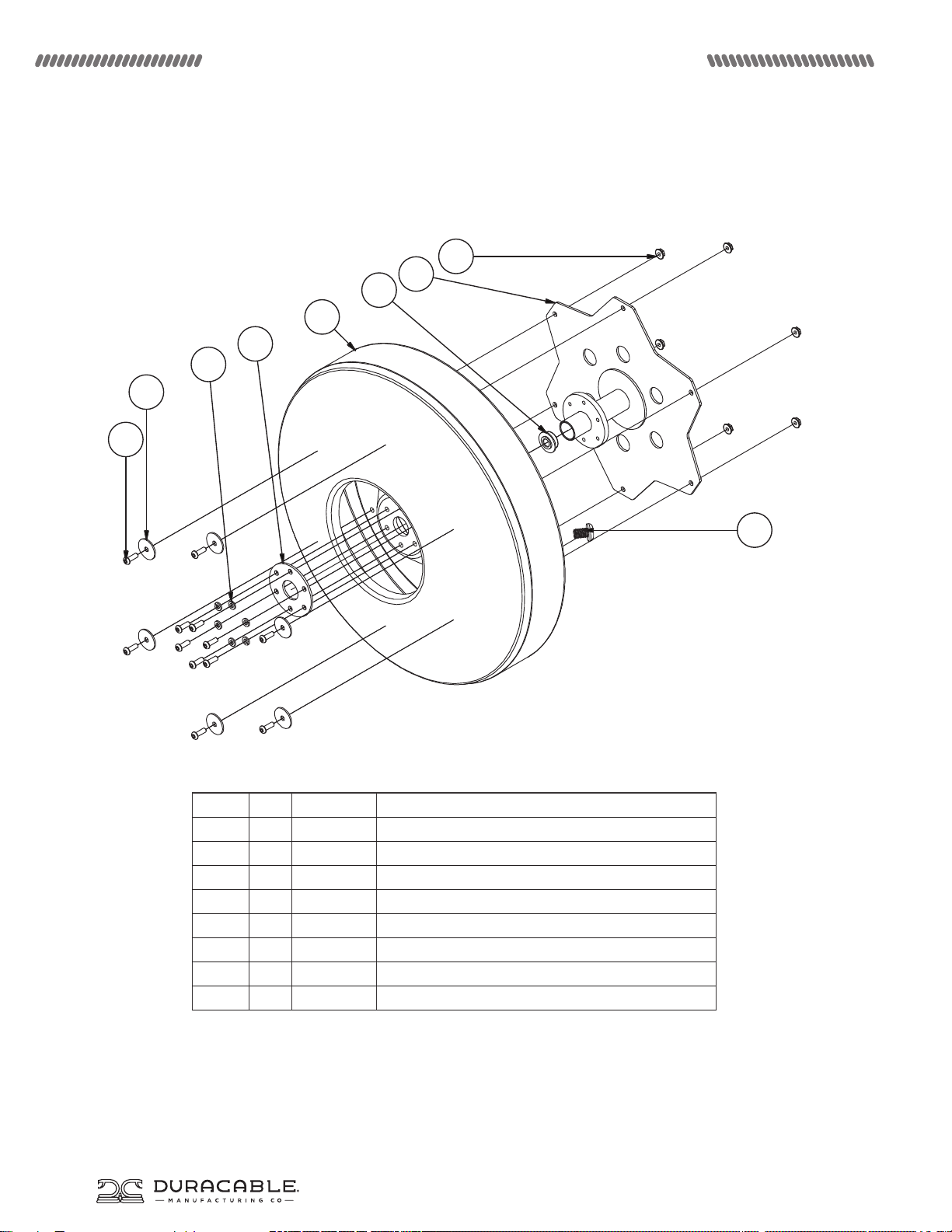
19PRS (19” Polyethylene Reel) Schematic for J-Maxx
Item Qty. Part# Description
1 1 D1HF Inner Clamp Washer
2 1 D6A Reel Bearing
2 6 WA22 .25 Lock Washer
3 6 WA47 .25 Body Washer
4 12 SHCS34 1/4-20 x 7/8 SBHS
5 6 FLNUT5 .25-20 Flange Nut
6 1 771409 Sled Plastic Drums Drive Hub Finished
8 1 MM60 .5-13 x .75 Std. Threaded Plug
9 1 771900 19” Sled Machine Plastic Drum
10
Page 11
J-MAXX MACHINE MANUAL
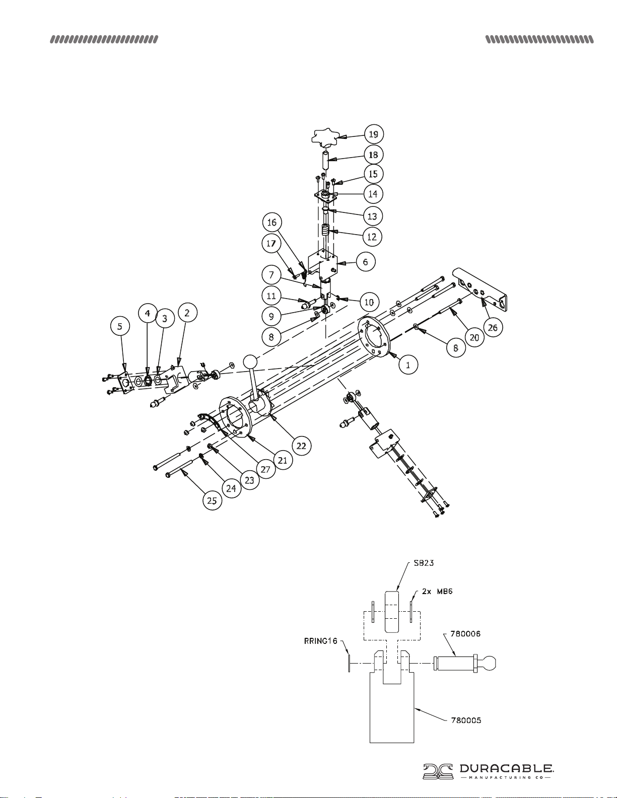
Mini Power cable feed and return SchematiC
Mini Power cable feed and return
Piston Kit SchematiC (Optional)
11
Page 12
J-MAXX MACHINE MANUAL
Mini Power cable feed and return SchematiC
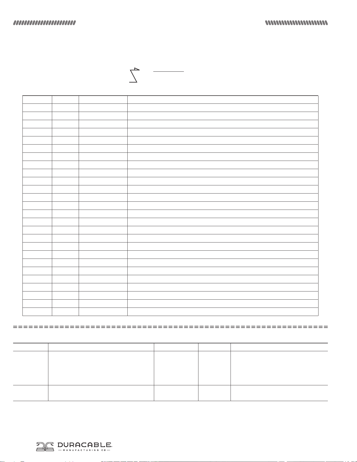
The entire line item in bold identifies the name of an entire assembly. The “Z” shaped
arrow identifies all the parts that make up that assembly. You can purchase the entire
assembly, or just the individual parts.
Item Qty. Part# Description
1 1 780009 Rear Plate
2 2 780001 Extruded Base Piston Housing w/Zirc3
3 4 MB5 .570 ID x .980 OD x .030 THK Thrust Washer
4 2 SB24 .566 ID x .986 OD x .078 WD Needle Thrust Bearing
5 2 780003 Base Piston Housing Back Plate
6 1 780002 Extruded Adjustable Piston Housing w/Zirc3
7 3 750005 Piston
8 10 MB6 .281 x .625 x .047 Stainless Thrust Washer
9 3 SB23 7 x 22 x 10.3 MM Roller Bearing
10 3 RRING16 7MM ‘E’ Clip
11 3 780006 .5 Ball Pivot Pin
12 1 SPR1 .15 x .75 x 1 Comp Spring
13 1 780007 .375 x .625 x .1875 Rest Pad
14 1 780004 Adjustable Piston Housing Backplate Weldment
15 12 PHSC13 10-24 x .5 PH Screw
16 1 SPR2 .042 DIA x 1.656 LG Expansion Spring
17 1 PHSC23 10-32 x .25 PH Screw
18 1 CPSS19 .5-13 x 2.5 Socket Set Screw
19 1 KNOB5 .5-13 x 2.75 Knob
20 4 HHCS53 .25-20 x 2.75 Hex Screw
21 1 780011 Front Plate
22 1 780008 Feed Directional Shifter Assembly Weldment w/Knob2
23 4 LN1 .25-20 Hex Lock Nut
24 2 WA22 .25 Lock Washer
25 2 HHCS54 .25-20 x 3.25 Hex Screw
26 1 780012 1100 - 3100 - 5200 Mount Bracket
27 1 780010 Arc R-N-F Decal
Power Cable Feed and Return Kits (Optional)
Kit Part # Description Included Parts Quantity Description of Included Parts
780005K Mini Power Cable Feed and Return Piston Kit 780005
780006
SB23
MB6
RRING16
SB23K Mini Power Cable Feed and Return Bearing Kit SB23
MB6
1
1
1
2
1
1
2
Upper/Lower Piston
Ball Pivot Pin
Roller Bearing
Thrust Washer
“E” Ring Clip
Roller Bearing
Thrust Washer
12
Page 13
J-MAXX MACHINE MANUAL
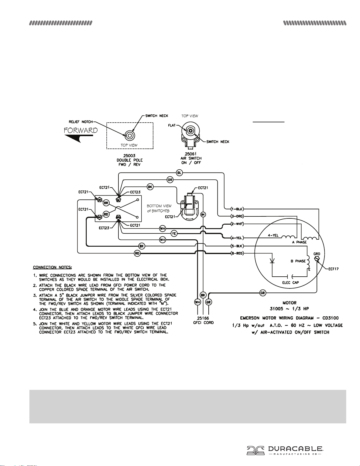
Electrical Schematic
MOTOR LEADS
#1 - BLUE
#2 - WHITE
#3 - ORANGE
#4 - YELLOW
#5 - BLACK
#8 - RED
The wiring diagram for the basic J-Maxx is shown above. If you experience any electrical diculties in operating your machine,
or you notice any frayed or inadequate wiring, or wiring that does not conform to the diagram, discontinue use of your machine
immediately and have a qualified electrician repair it, or return it for repair to Duracable Manufacturing.
13
Page 14
J-MAXX MACHINE MANUAL
Electrical Safety
Handle with Care
Most of us take electricity for granted. It has been with us
since the day we were born. We use it every day for light,
phone, home appliances, tools, and other equipment that
helps us maintain our standard of living. Although electricity
is one of the safest energy forms, we tend to forget how
powerful and dangerous it can be if not used properly.
Every year many people are injured or killed by electricity.
Most of these accidents could have been prevented with
simple precautions and careful use of electricity. Following are
some tips to help avoid electrical accidents. Read through this
information. Be sure you understand its importance. If you have
questions or feel you may have a potential electrical hazard, tell
your supervisor or call a qualified electrician immediately.
General Electrical Guidelines
Remember, electricity is always trying to make a circuit. It can
travel through an electric wire, metal pipe, or even your body.
Electrical shock can occur when you come in contact with an
energized electrical unit and a good conductor. Shock can range
from a slight tingle to a severe burn, or death by electrocution.
Electrical accidents happen in everyday situations. Most
electrocutions occur in a wet environment or when an electrical
product is being repaired or installed. Think about, and take
precautions against, potentially dangerous situations. When
disconnecting electrical cords, pull on the plug rather than the
cord to avoid damage. Use rubber gloves and rubber boots or
insulated shoes to protect yourself, especially if you are in a wet
or damp environment. Before using this machine, make sure a
properly grounded, three-prong, 110-volt outlet is available.
Where it is not available, use a three-prong adapter and connect
the grounding lug to a known ground. Never cut o a grounding
prong to fit a two-prong outlet. This eliminates the ground
protection.
Electrical Procedures
Do not leave the machine plugged in when not in use. Even with
the switch o, a machine can shock or electrocute its handler.
The J-Maxx machine must be grounded to protect the operator
from shock. This is accomplished by using the Ground Fault
Circuit Interrupter Cord (GFCI) to ensure proper grounding.
Check electrical cords before each use for signs of damage.
Repair or replace cords which are pinched, cracked, frayed, or
worn. Remember, the GFCI oers no protection against electric
shock for wiring preceding it in the system. Your GFCI is directwired to the machine, plug the GFCI into the power source
receptacle.Discontinue use and repair immediately any machine
that causes the slightest shock or is damaged in any way. It
could lead to a serious electrical shock or electrocution. Inspect
the machine daily for wear or damage that might expose live
electrical parts.
Ground Fault Circuit Interrupters (GFCI)
A GFCI works by detecting changes in electrical current flow.
It breaks the circuit before serious injury can occur. For your
protection, heed the “DANGER” warning on the machine cover
an use the GFCI cord. The GFCI must be tested before each use.
Use the following procedure:
• Insert the unit into a 110-volt, AC-grounded receptacle;
• Push the “test” button in - the red indicator light should go o;
• Push the “reset” button in - if the red indicator light goes on,
the unit is ready for use;
• Do not use the unit if the light does not go on when reset;
• Do not use the unit if the indicator light remains on when the
test button is pushed.
Extension Cords
• Use extension cords only when necessary.
• Position cords in use to prevent tripping hazards. Do not place
them in areas where they can be damaged by trac.
• Avoid coiling extension cords during use to prevent possible
overheating of the cord.
• Discard cracked or damaged cords.
• The following cord sizes and lengths should be observed
according to the National Electrical Code when using this
machine:
• 12 gauge wire - 75’ of cord, including 25’ of GFCI cord.
• 14 gauge wire - 50’ of cord, including 25’ of GFCI cord.
• Cord sizes smaller than 12 gauge should not be used for 3/4
HP motors. Larger gauge cords can be run greater distances,
but are not practical because of their size and weight.
• To protect your motor, observe the guidelines mentioned. If
you have a run more than 75’, use a generator to reduce your
cord length from the power source to a working distance
within these guidelines.
Overhead Power Lines
• When working outdoors, keep clear from overhead power
lines in all directions.
• Check the location of power lines before using a ladder. Use
approved ladders made of non-conductive material.
• Never place a ladder where it can slide into a power line.
• When carrying or moving a ladder or equipment, lower it to
avoid touching a power line.
• Never assume that a wire is safe to touch.
14
Page 15
J-MAXX MACHINE MANUAL
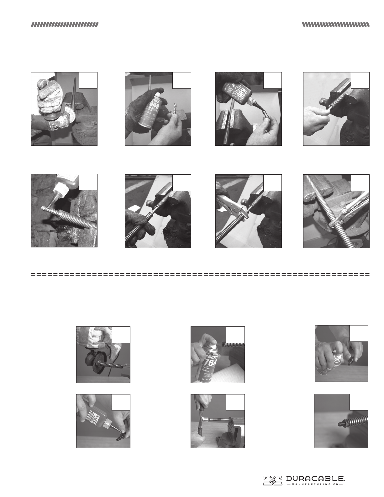
How to splice duraflex® cable
1 2 3 4
1. Cut a few inches off of each
cable end and remove any burrs
with a grinding disk or file.
5
5. Apply Loctite Retaining
Compound to other end of splice
core.
2. Spray Loctite Primer in and
around the cable end and splice
core to thoroughly remove
grease and grime.
6 7 8
6. Align other piece of cable onto
splice core.
How to Bond End Fittings to duraflex
You can attach end fittings and splice cores to DuraFlex cable using a chemical bonding process, which means you can make quick cable repairs on
the job—without welding. With Loctite Primer and Loctite Retaining Compound, you can quickly create a dependable bond that is as strong as a
conventional weld. Please note that these products are not the same thread-locking compounds available in hardware stores and plumbing-supply
houses, they are heavy-duty, permanent-bonding compounds made especially for jobs such as bonding cable fittings.
1. Cut the cable
end and remove
any burrs with a
grinding disk or
file.
1
2. Spray Loctite
Primer in and
around the
cable end to
thoroughly
remove grease
and grime.
3. Apply Loctite Retaining
Compound to splice core.
7. Place vise grips on free cable
end and turn counterclockwise.
®
cable
2
3. Spray Loctite
Primer on the
end fitting to
thoroughly
remove grease
and grime.
4. Insert splice core into cable
one turn.
8. Continue turning and the
cable ends will meet at the
center of the splice core.
3
4. Apply Loctite
Retaining
Compound to the
end fitting.
5. Using the
4 5
wrench (part
number EW),
screw the fitting
into the cable
end until fitting
is totally sealed.
6. The Retaining
Compound will be
fully bonded to
the cable in just a
few minutes.
6
15
Page 16
j-maxx Machine Manual
j-maxx
300 ASHWORTH ROAD
WEST DES MOINES, IOWA 50265
DURACABLE.COM 800.247.4081
ANSWER LINE: 877.257.1781
FAX: 515.223.6109
JMXMM
UPDATED JUNE 2017
 Loading...