

Page 1

Page 2

2
Table of Contents
COPYRIGHT................................................................................................4
REGULA T ORY STATEMENT................................................................................4
Federal Communications Commission Statement..........................................................................................................4
Caution.............................................................................................................................................................................. 4
Declaration of Conformity...............................................................................................................................................4
RF exposure warning........................................................................................................................................................5
Canada, Industry Canada (IC) Notices...........................................................................................................................5
Battery Disposal................................................................................................................................................................6
CLASS 1 LASER PRODUCT...........................................................................................................................................6
FCC W arning....................................................................................................................................................................7
IC W arning........................................................................................................................................................................7
BEFORE YOU START ................................................................8
PACKAGE CONTENTS.....................................................................................8
COMPONENTS............................................................................................. 9
Front V iew.........................................................................................................................................................................9
Back V iew........................................................................................................................................................................ 11
Right V iew........................................................................................................................................................................12
Left V iew..........................................................................................................................................................................12
T op View...........................................................................................................................................................................13
Bottom V iew.....................................................................................................................................................................13
Status Indicators..............................................................................................................................................................14
GETTING STARTED................................................................ 15
P
OWERING UP YOUR TABLET PC..................................................................... 15
Using Battery Power.......................................................................................................................................................15
INST ALLING THE BATTERIES........................................................................... 15
Charging the Battery.......................................................................................................................................................16
Charging T ime.................................................................................................................................................................16
Checking the Battery Level.............................................................................................................................................17
When to replace the Battery P ack..................................................................................................................................18
Removing the Batteries...................................................................................................................................................18
ST AR T ING YOUR TABLET PC .......................................................................... 19
Turning On Your T ablet PC............................................................................................................................................19
Changing the Display Orientation.................................................................................................................................19
U
SING THE STYLUS .................................................................................... 19
Calibrate the Screen........................................................................................................................................................19
Page 3

USING THE BIOS SETUP UTILITY..........................................21
BIOS SETUP MENU.................................................................................... 21
ST ARTING THE BIOS SETUP UTILITY................................................................ 21
NAVIGATING AND ENTERING INFORMATION IN BIOS.............................................. 22
OPTIONAL DEVICES .............................................................. 23
MAGNETIC STRIPE READER (MSR).................................................................. 23
MSR Specification...........................................................................................................................................................23
PIN PAD ................................................................................................. 24
SPECIFICATIONS ..................................................................25
Page 4

Preface
4
Copyright
Copyright© 2012. All rights reserved.
No part of this user manual may be transmitted, stored in a retrieval system, or
translated into any language or computer language, in any form or by any
means, without the prior written permission of the manufacturer. Information is
subject to change without prior notice.
Regulatory Statement
Federal Communications Commission Statement
This equipment has been tested and found to comply with the limits for a Class
B digital device, pursuant to Part 15 of the FCC Rules. These limits are designed
to provide reasonable protection against harmful interference in a residential
installation. This equipment generates, uses, and can radiate r a dio frequency
energy and, if not installed and used in accordance with the instructions, may
cause harmful interference to radio communications. However, there is no
guarantee that interference will not occur in a particular installation. If this
equipment does cause harmful interference to radio or television reception,
which can be determined by turning the equipment off and on, the user is
encouraged to try to correct the interference by one or more of the following
measures:
Reorient or relocate the receiving antenna.
Increase the separation between the equipment and the receiver.
Connect the equipment into an outlet on a circuit different from that to
which the receiver is connected.
Consult the dealer or an experienced radio/TV technician for help.
Shielded interconnect cables and shielded AC power cable must be employed
with this equipment to insure compliance with the pertinent RF emission limits
governing this device. Changes or modifications not expressly approved by the
system's manufacturer could void the user's authority to operate the equipment.
Caution
Any changes or modifications not expressly approved by the grantee of this
device could void the user’s authority to operate the equipment.
Declaration of Conformity
This device complies with part 15 of the FCC rules. Operation is subject to the
following conditions:
This device may not cause harmful interference
This device must accept any interference received, including interference
that may cause undesired operation.
Page 5

Preface
5
RF exposure warning
This equipment must be installed and operated in accordance with provided
instructions and must not be co-located or operating in conjunction with any
other antenna or transmitter. End-users and installers must be provided with
antenna installation instructions and transmitter operating conditions for
satisfying RF exposure compliance.
SAR Value: 1.119W/kg
Canada, Industry Canada (IC) Notices
This Class B digital apparatus complies with Canadian ICES-003 and RSS-210.
Operation is subject to the following two conditions: (1) this device may not
cause interference, and (2) this device must accept any interference, including
interference that may cause undesired operation of the device.
Radio Frequency (RF) Exposure Information
The radiated output power of the Wireless Device is below the Industry Canada
(IC) radio frequency exposure limits. The Wireless Device should be used in such
a manner such that the potential for human contact during normal operation is
minimized.
This device has been evaluated for and shown compliant with the IC Specific
Absorption Rate (“SAR”) limits when installed in specific host products operated
in portable exposure conditions.
Canada, avis d'Industry Canada (IC)
Cet appareil numérique de classe B est conforme aux normes canadiennes ICES003 et RSS-210.
Son fonctionnement est soumis aux deux conditions suivantes : (1) cet appareil
ne doit pas causer d'interférence et (2) cet appareil doit accepter toute
interférence, notamment les interférences qui peuvent affecter son
fonctionnement.
Page 6

Preface
6
Informations concernant l'exposition aux fréquences radio (RF)
La puissance de sortie émise par l’appareil de sans fil est inférieure à la limite
d'exposition aux fréquences radio d'Industry Canada (IC). Utilisez l’appareil de
sans fil de façon à minimiser les contacts humains lors du fonctionnement normal.
Ce périphérique a été évalué et démontré conforme aux limites SAR (Specific
Absorption Rate – Taux d'absorption spécifique) d'IC lorsqu'il est installé dans
des produits hôtes particuliers qui fonctionnent dans des conditions d'exposition
à des appareils portables.
Battery Disposal
THIS PRODUCT CONT AINS A LITHIUM- ION OR NICKEL-METAL HYDRIDE
BATTERY. IT MUST BE DISPOSED OF PROPERLY. C ONTACT LOCAL
ENVIRONMENT AL AGENCIES FOR INFORMATION ON RECYCLING AND
DISPOSAL PLANS IN YOUR AREA.
CLASS 1 LASER PRODUCT
LASERSCHUTZKLASSE 1 PRODUKT TO EN60825
CAUTION:
THIS APPLIANCE CONTAINS A LASER SYSTEM AND IS
CLASSIFIED AS A "CLASS 1 LASER PRODUCT.” TO USE THIS
MODEL PROPERLY, READ THE INSTRUCTION MANUAL
CAREFULLY AND KEEP THIS MANUAL FOR FUTURE REFERENCE.
IN CASE OF ANY TROUBLE WITH THIS MODEL, PLEASE CONTACT
YOUR NEAREST "AUTHORIZED SERVICE STATION.” TO PREVENT
DIRECT EXPOSURE TO THE LASER BEAM, DO NOT TRY TO OPEN
THIS ENCLOSURE.
ANNEX IV
Symbol for the marking of electrical and electronic equipment
The symbol indicating separate collection for electrical and electronic equipment
consists of the crossed-out wheeled bin, as shown below. The symbol must be
printed visibly, legibly and indelibly .
Page 7

Preface
7
CAUTION FOR ADAPTER
THIS TABLET PC IS FOR USE WITH DEDICATED AC ADAPTER.
BATTERY SAFETY
DANGER OF EXPLOSION IF BATTERY IS INCORRECTLY REPLACED.
REPLACE ONLY WITH THE SAME OR EQUIVALENT TYPE RECOMMENDED BY THE
MANUFACTURER. DISPOSE OF USED BATTERIES ACCORDING TO THE
MANUFACTURER'S INSTRUCTIONS.
CAUTION FOR RJ-45
The RJ-45 jack is not used for telephone line connection.
FCC Warning
This device complies with part 15 of the FCC Rules. Operation is subject to the
following two conditions:
1. This device may not cause harmful interference, and
2. this device must accept any interference received, including
interference that may cause undesired operation.
IC Warning
This Class B digital apparatus complies with Canadian ICES-003.
Cet appareil numerique de la classe B est conforme a la norme NMB-003 du
Canada.
Page 8
Before You Start
8
Before You Start
Congratulations on your purchase of this tablet PC.
This rugged tablet PC is portable and provides users with maximum mobile
computing experience in a wide range of working environments. Before you
begin using your tablet PC, read this chapter to familiarize yourself with the main
components installed in the system.
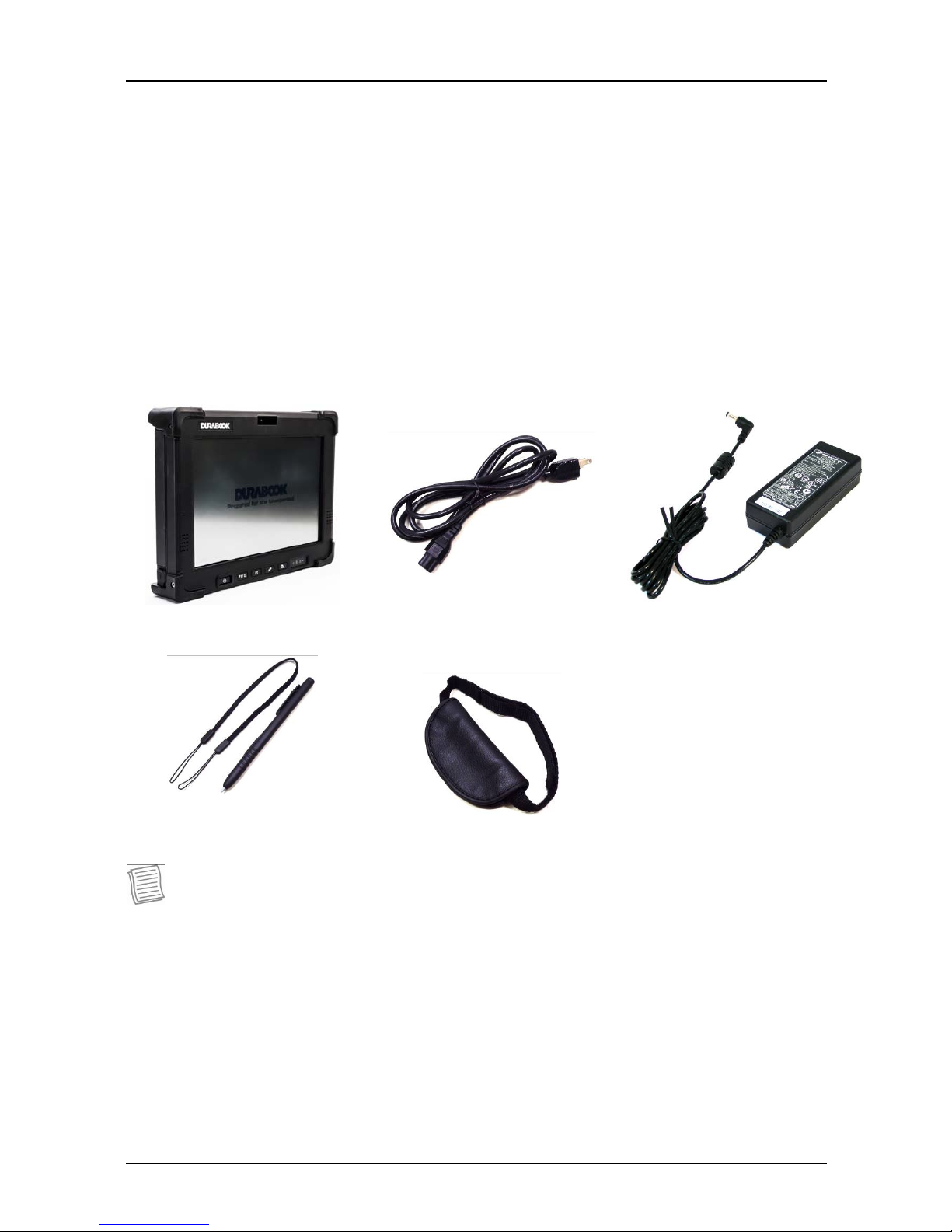
Package Contents
If any of following item is damaged, please contact your retailer.
Tablet PC Power cord Power adapter
Stylus Pen Hand-strap
NOTE
The pictures are for reference only, actual items may slightly differ.
Page 9
Before You Start
9
Components
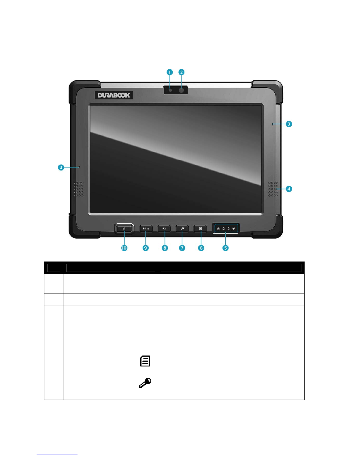
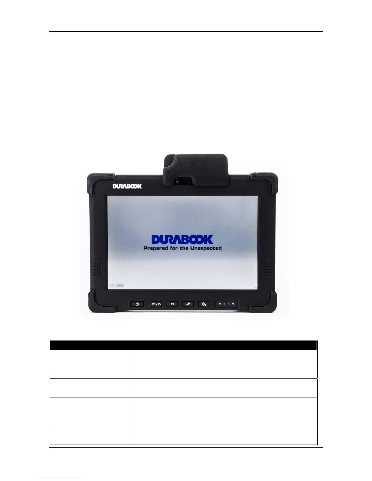
Front View
No. Item Description
1 Light Sensor Sense the ambient light condition for auto
backlight setting function.
2 Webcam Use for video conference.
3 Microphone Receive audio input.
4 Speaker Emit sound.
5 Status Indicators (Power,
Battery, Wireless)
Indicate the corresponding function status.
See “Status Indicators” on page 14.
6 Quick Menu button
Press to launch the Quick Menu.
7 Lock button
Press to launch the log in menu, similar as
pressing <Ctrl> + <Alt> + <Del> on a
PC.
Page 10
Before You Start
10
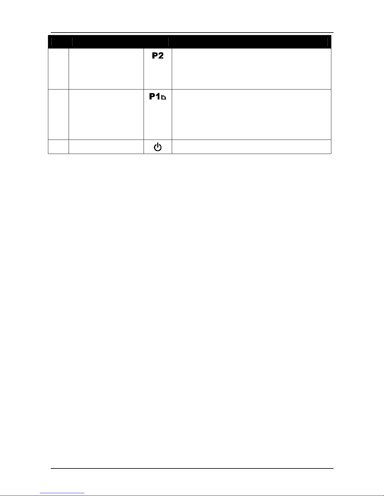
No. Item Description
8 Function button
(P2)
Press to launch an application assigned to
the button. See “錯誤! 找不到參照來源。 on
page 錯誤! 尚未定義書籤。” to program the
function button.
9 Function (P1) /
Rotate button
By default, press this button to rotate the
display 90° clockwise. Or, press this button
to launch an assigned application. See “錯
誤! 找不到參照來源。 on page 錯誤! 尚未定義
書籤。” to program the function button.
10 Power button
Press to power on and off the tablet PC.
Page 11
Before You Start
11
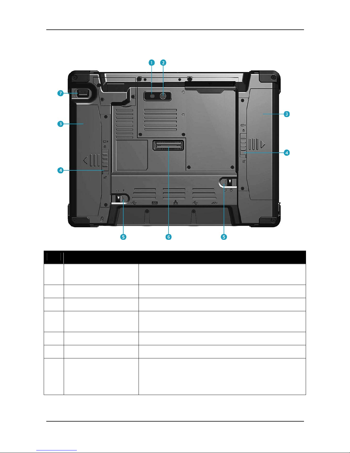
Back View
No. Item Description
1 Camera LED flash Provide additional lighting when taking pictures
under low light environment.
2 Camera Use to take pictures.
3 Battery pack Supply battery power to your tablet PC.
4 Battery latch Slide down the latch to release the battery pack
from the compartment.
5 Battery lock Lock the battery latch.
6 Docking connector Connect the tablet PC to a docking station.
7 Scanner button Press to trigger the Barcode scan function if the
barcode scanner is on. It can also be assigned as
the camera button in
Quick Menu.
Page 12
Before You Start
12
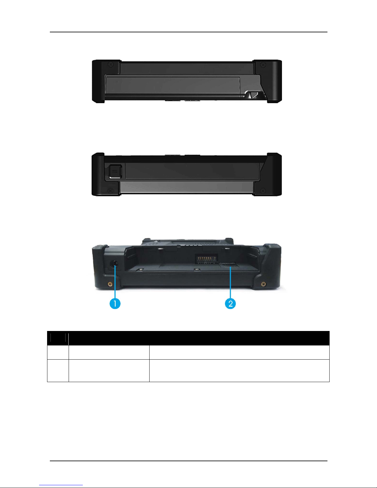
Right View
Left View
With battery pack
Without battery pack
No. Item Description
1 DC-in jack Connect the power adapter.
2 SIM card slot Use to insert a SIM card for WWAN, Gobi 3000, or
LTE module connection.
Page 13
Before You Start
13
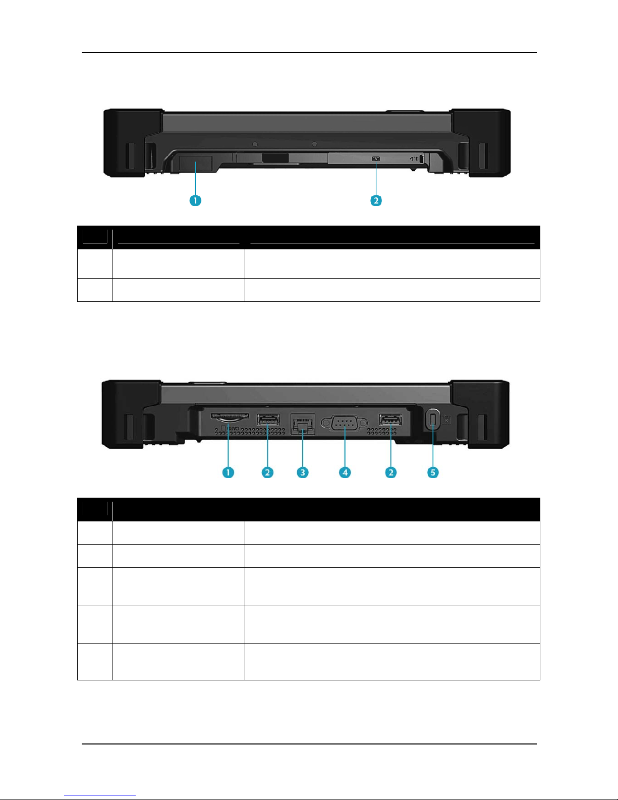
Top View
No. Item Description
1 Barcode scanner Use to scan for barcodes.
2 Smart card reader Use to insert smart cards.
Bottom View
No. Item Description
1 SD card slot Use to insert an SD card for external storage.
2 USB port Connect USB peripheral devices.
3 LAN (RJ-45) port
Connect to a local area network (LAN) using an
Ethernet cable.
4 Serial port (RS-232) Connect a peripheral device, such as a printer or
other device with serial port.
5 Kensington lock slot Connect to a Kensington-compatible tablet PC
security lock.
Page 14
Before You Start
14
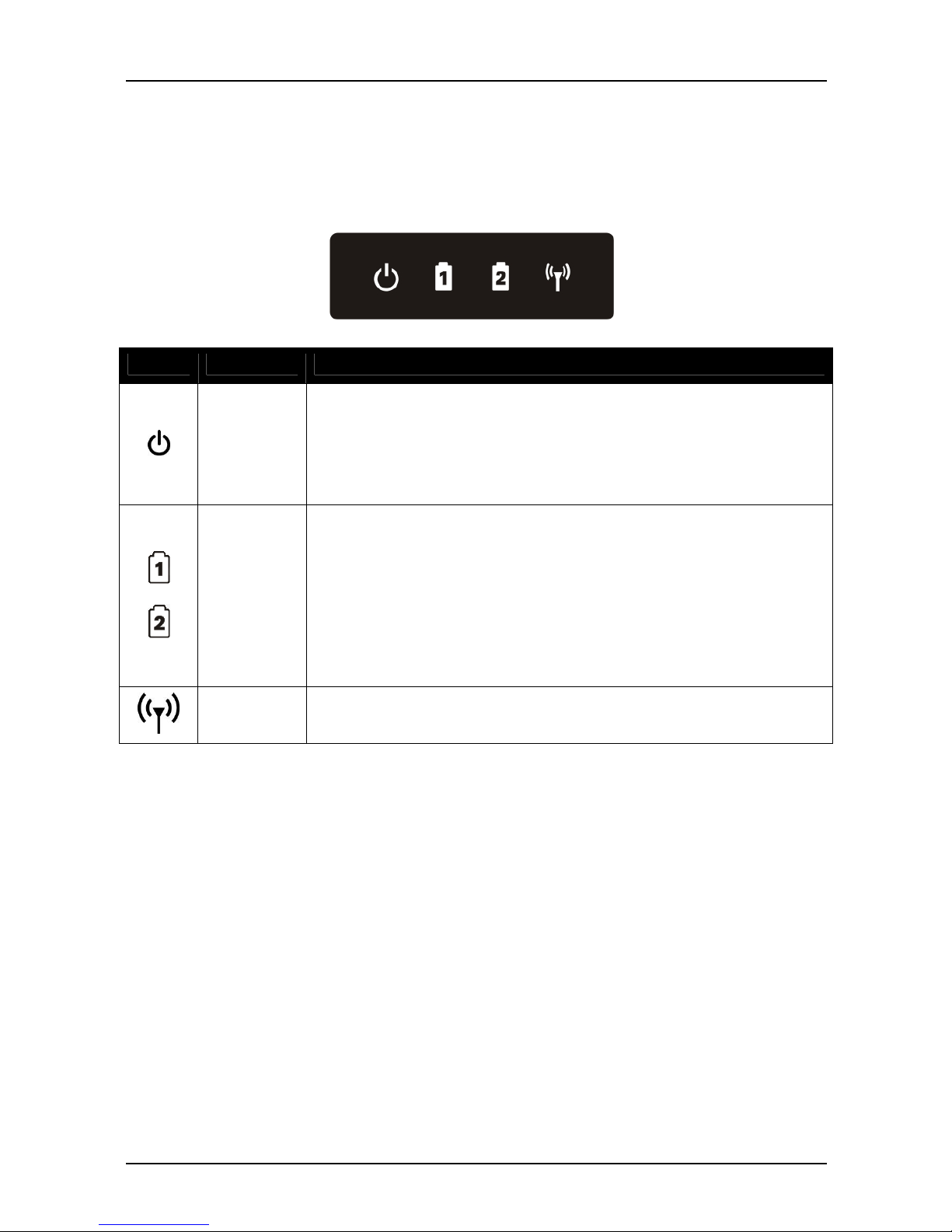
Status Indicators
The status indicators in the lower right corner of the tablet PC light up when a
particular function of the tablet PC is active. Each indicator is marked with a
symbol.
Icon Item Description
Power
Indicate the power status:
Off: Power is off or the tablet PC is in hibernate mode.
Green: Power is on.
Blinking Green: The tablet PC is in standby or sleep
mode.
Battery
Indicate the status of battery 1 and battery 2:
Green: The battery is fully charged with 95% power or
above.
Orange: The battery is charging.
Flashing Orange: Charging error.
Red: The battery is low with less than 10% power.
Off: The battery is discharged.
RF
The RF LED lights blue when the wireless (WLAN) and/or
Bluetooth function is enabled.
Page 15
Getting Started
15
Getting Started
This chapter will guide you on how to use your tablet PC.
Powering Up Your Tablet PC
Your tablet PC can be powered up using the AC adapter or the Lithium-ion
battery.
Using Battery Power
1. Install a charged battery in the battery compartment.
2. Remove the AC adapter (if plugged). Your tablet PC will automatically use
the battery power.
NOTE
If your tablet PC is connected to an electrical outlet and the battery is
installed, your tablet PC uses power from the electrical outlet.
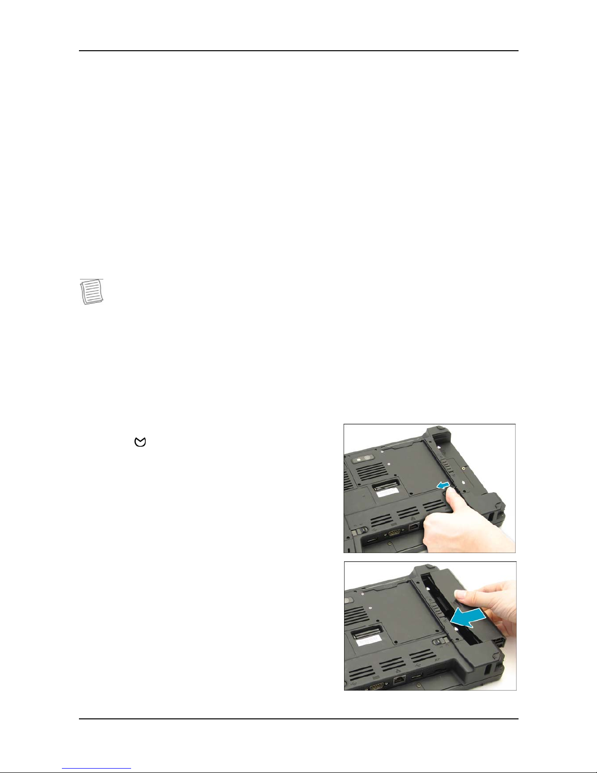
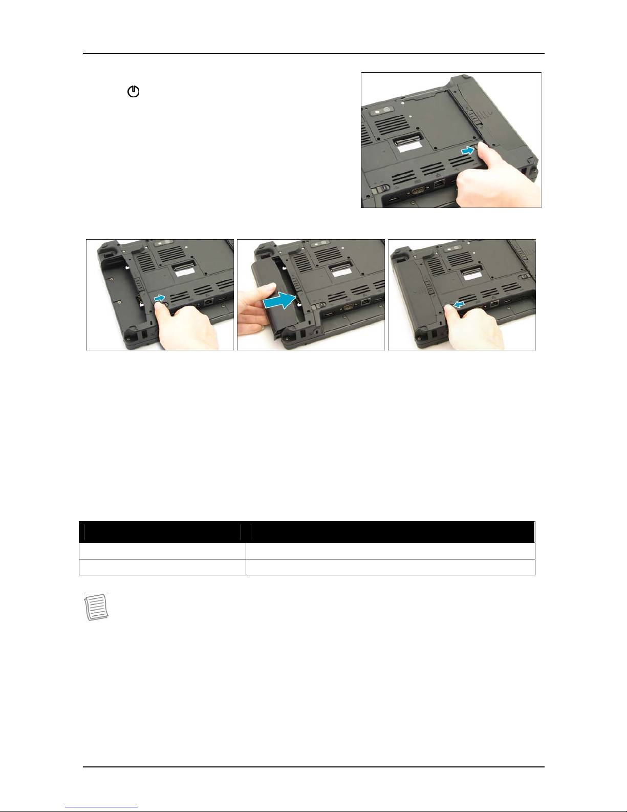
Installing the Batteries
To install the batteries, follow the steps below:
1. Make sure the battery lock is in the
unlock position.
2. Slide the battery pack into the
compartment and push completely until
the battery locks into place.
Page 16
Getting Started
16
3. Slide the battery lock to the
lock position.
4. Repeat steps 1 to 3 to insert the second battery.
Charging the Battery
The Lithium-ion battery is not fully-charged upon purchase.
To charge the battery, follow the steps below:
1. Install the battery to your tablet PC.
2. Connect the AC adapter to the DC-in jack of your tablet PC.
3. Connect the AC adapter to the power cord.
4. Plug the power cord to an electrical outlet.
Charging Time
Number of battery pack Charging duration (at 25ºC)
1 3.5 hours
2 6.5 hours
NOTE
The charging time may be longer if you are using your tablet PC while
charging the battery.
CAUTION
DO NOT charge the battery if the temperature is below 0ºC or higher than
60ºC.
Use only the supplied AC adapter. Using other AC adapters may damage the
battery or your tablet PC.
Page 17

Getting Started
17
Checking the Battery Level
It is important that you monitor the battery status regularly to ensure you do not
run out of power at a critical moment.
To check the remaining battery power, double tap the battery icon in the system
tray. The battery screen appears:
Page 18
Getting Started
18
When to replace the Battery Pack
The battery performance gradually decreases over time and usage. We
recommend you to replace your battery pack after 18 to 24 months of usage.
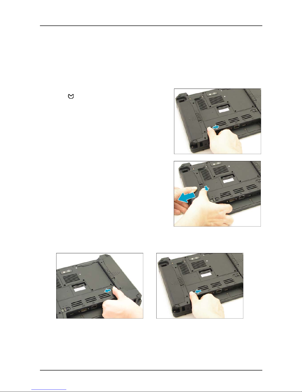
Removing the Batteries
To remove the batteries, follow the steps below:
1. Slide the battery lock to the
unlock position.
2. Press and hold down the battery latch and
slide the battery to remove it from the
compartment.
3. Repeat steps 1 and 2 to remove another battery.
Page 19
Getting Started
19
Starting Your Tablet PC
Turning On Your Tablet PC
Press the button until the Power LED lights up.
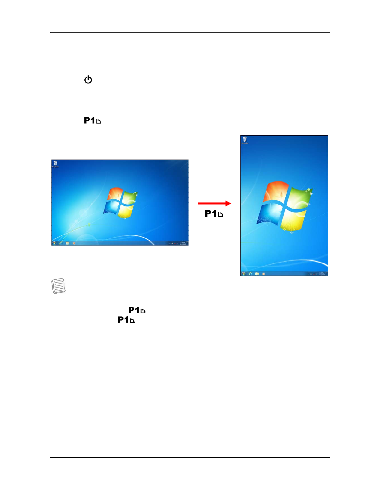
Changing the Display Orientation
Y ou can rotate the displa y orientation to suit yo ur preference.
Press the button to rotate the display 90°, 180°, and 270° clockwise.
NOTE
Y ou need to disable the Auto Rotate option in the Quick menu before pressing
the shortcut button ( ) to rotate the display.
Repeatedly press to rotate the display 180° and 270° clockwise.
Using the Stylus
This tablet PC may come with an integrated stylus for accurate control input to
the LCD touch panel. You can use the stylus to point, select, or drag items or
objects on the screen.
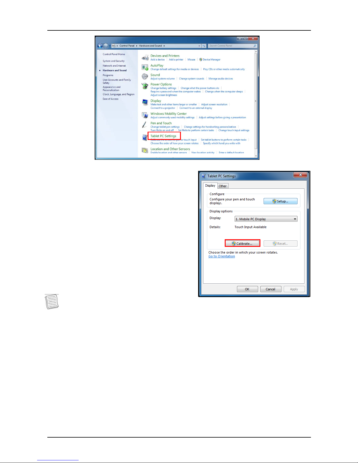
Calibrate the Screen
To ensure touch accuracy, calibrate the screen.
1. Tap Start > Control Panel.
2. Select Hardware and Sound > Tablet PC Settings.
Page 20
Specifications
20
3. Tap Calibrate.
4. Follow the on-screen instructions to
complete screen calibration.
NOTE:
If the optional digitizer is enabled, use a pencil to do the touch panel
calibration instead of using the digitizer pen.
Page 21
Specifications
21
Using the BIOS Setup
Utility
Your tablet PC has a BIOS setup utility which allows you to configure important
system settings, including settings for various optional functions of the tablet PC.
This chapter explains how to use the BIOS setup utility.
BIOS Setup Menu
The BIOS Setup Utility allows you to configure your tablet PC basic settings.
When you turn your tablet PC on, the system reads this information to initialize
the hardware so that it can operate correctly. Use the BIOS setup utility to
change your tablet PC start-up configuration. For example, you can change the
security and power management routines of your system.
Starting the BIOS Setup Utility
You can only enter the BIOS setup utility as the tablet PC is booting, that is
between the time you turn on the tablet PC and before the Windows interface
appears.
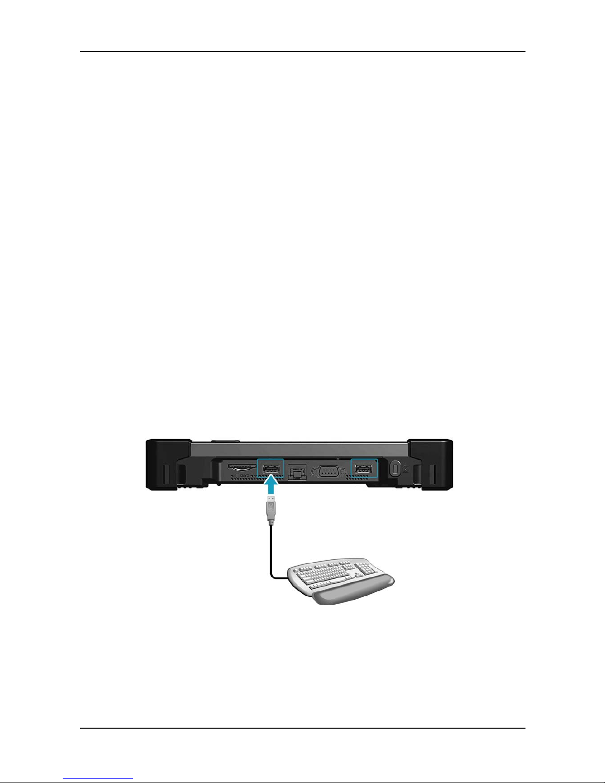
1. Connect a USB keyboard to one of the USB ports of your tablet PC.
2. If your tablet PC is already on, restart your tablet PC.
3. When the start up logo appears, press the <Enter> key on the USB keyboard
to enter the setup utility.
Page 22

Specifications
22
Navigating and Entering
Information in BIOS
Use the following keys to move between fields and to enter information:
External
Keyboard
Description
Selects screen.
Moves up/down to select items.
Enter Confirms the selection and enters the selected menu screen.
+ / - Changes an option for the selected items.
F1 Displays the Help screen.
F2 Invokes the previous values.
F3 Loads optimized default values.
F4 Saves the changes and exits Setup.
Esc
Exits any section. If you wish to exit the BIOS utility without
saving changes or go to the main menu, then press this key.
Users are allowed to enter new values to replace the default settings in certain
fields and some fields are specified by system default parameters and cannot be
modified by users. Reverse the attribute of the main options and press the
<Enter> or button to enter a submenu. Press the <Esc> button to return to
the previous configuration page.
Page 23
Specifications
23
Optional Devices
The functionality of your Tablet PC can be expanded with the use of devices,
such as the Magnetic Stripe Reader (MSR), Pin Pad, and others. These devices
are optional items and may be purchased separately.
Magnetic Stripe Reader (MSR)
The integrated Magnetic Stripe Reader (MSR) can be installed on yo ur Tablet PC
as shown below.
MSR Specification
MSR Specification
Supported Protocol
ANSI/ISO 7810, ISO 7811-1/6, 7813, JIS X6301, X6302,
AAMVA
Frequency
Two-frequency coherent phase (F2F) recording methods
ISO
ISO Track1 - IATA , Track2 - ABA and Track3 - THRIFT
decoding methods
Reading and
Encryption
Bi-directional card reading
Supplies 54 byte value
Encrypts all track data and the value
Speed
Card speed through the unit may vary from 3 ips to 100 ips (7
cm/s to 250 cm/s)
Page 24
Specifications
24
Pin Pad
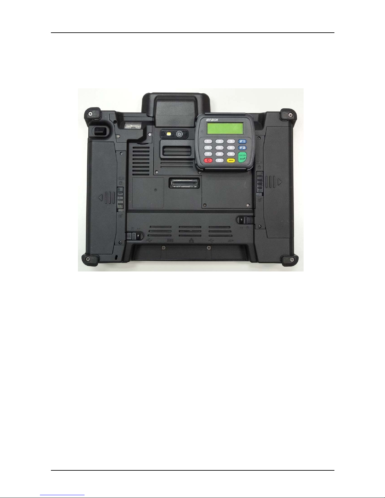
The Pin pad is designed with a ready-to-use interface. Install the Pin pad on the
back of your Tablet PC as shown below.
Page 25
Specifications
25
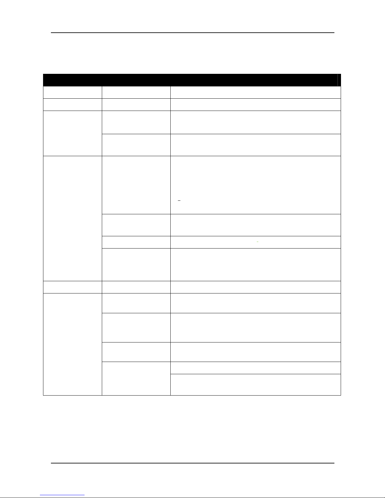
Specifications
Features Specifications
Processor Type & Speed Intel Atom N2600 1.6GHz 512KB x2 L2 cache
Chipset
NM10
Type
DDRIII 800
One 204-pin DDRIII SODIMM sockets for 2GB
System
Memory
Maximum
Memory
2GB
Display
Standard:
10.1” WXGA (1280x800) TFT LCD with resistive
multi-touch panel
Optional Sunlight readable:
10.1” WXGA (1280x800) TFT LCD with sunlight
readable resistive multi-touch panel
Screen Autorotation
Support screen auto-rotation
Light Sensor
Built-in ambient light sensor
Display
Digitizer
Optional Digitizer with active stylus pen with
USB interface battery-charger
Auto switch between digitizer and touch input
Storage SSD
mSA TA SSD 32/64/128 GB
Expansion Slot Smart card reader
SD card slot (SDHC)
Camera
Front facing 1.3M pixel camera
Optional rear facing 5M pixel auto-focus
camera
Barcode scanner
Optional Barcode scanner, support 1D/2D
barcode
Internal 10/100/1000M bit Ethernet LAN
I/O Devices
Communications
Intel Centrino Wireless N 135 (WLAN 1x1 b/g/n
and Bluetooth 4.0 EDR)
Page 26
Specifications
26
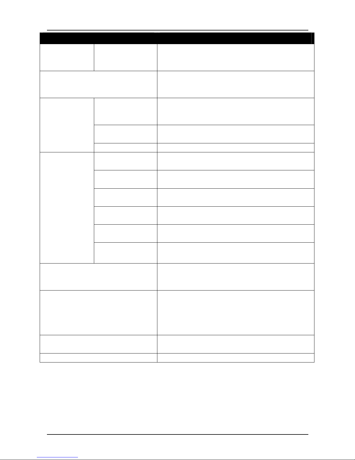
Features Specifications
I/O Devices I/O P orts
Bottom Side I/O: RS-232x1, RJ 45x1, USB
2.0x2, DC-inx1
Rear Side I/O: Docking connector x1
Audio
HD Audio
One speaker
Analog Mic. Array (With 2 Microphones)
AC/DC Adapter Input:100V-240V, 50Hz-60Hz,
Output:19V, 3.42A; 65W
Compliant with Energy Star 5.2
Battery Module Two Li-Ion battery packs
(11.1V, 2600mAh, 28.86 W)
Power
Battery Life 7~8 hrs
Operating
Temperature
-20°C ~ 45°C
Storage
Temperature
-33°C ~71°C
Operating
Humidity
5% ~ 95%
Drop 26 drops with 4 feet high to 2” plywood over
concrete, unit on with SSD
Dust Proof/Water
Sealing
IP-4X / IP-X3
Environment
Vibration MIL-STD 810G 514.6 Procedure I category 24
Figure 514.6E-1, unit on with SSD
Operating System Windows 7 Professional x86
Windows Embedded Standard 7 (by customer
request)
Security Computrace Enable BIOS
Administrator password
Boot password
TPM 1.2 (PCBA option)
Kensington Lock slot
Dimensions 274 (W) x 202 (H) x 45.9 (D) mm /
10.8 (W) x 8.0 (H) x 1.8 (D) inch
Weight Weight: 1.47 kg / 3.24 lbs
Specifications are subject to change without prior notice.
 Loading...