

dupol up200-gsm User Manual
UP200-GSM Rev.1.2 08/01/2014
UP200-GSM
Intercom and access control unit
operating on mobile GSM network
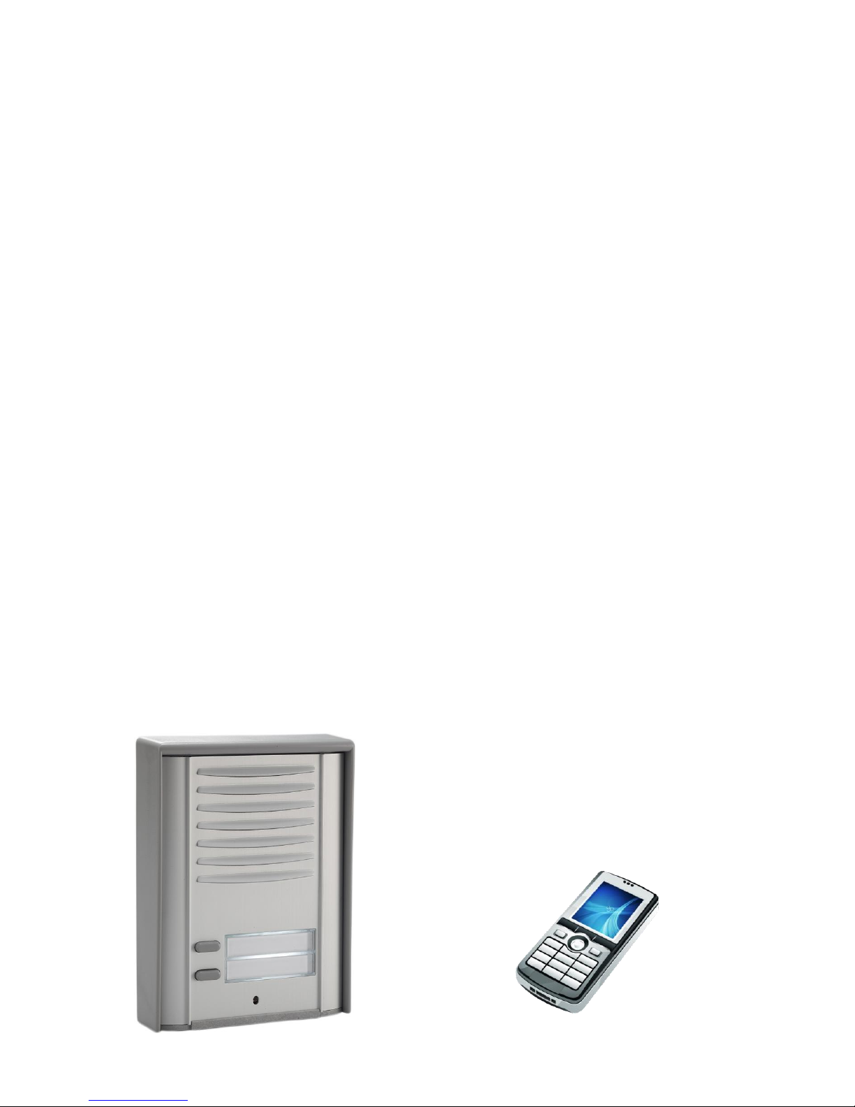
INTRODUCTION
The UP200-GSM is an intercom unit which as a cell
phone can call the owner’s mobile or landline phone.
By pressing the call button on the intercom, it makes
the voice connection in a few seconds, just like when
talking via a conventional intercom system. This way it
makes possible for the owner to receive the visitor’s
calls and talk to them at anytime and anywhere, even
when not at home.
The unit does not need any special installation or
complicated wiring, it needs power only and an active
SIM card.
FUNCTIONS
Wireless intercom with 2 pushbuttons
(for 1 or 2 apartments)
2 phone numbers can be assigned to each
pushbutton (set as primary and secondary)
Gate control function by free call, 100 user phone
numbers can be configured
Direct control for electric lock, can be controlled
during the conversation using the phone’s keys
The output can be activated by pushing the unit’s
call button (existing doorbell can be connected)
The outputs can be controlled by the contact input
(optional button for local control of the electric lock)
SMS forwarding (e.g. to forward the balance
information of pre-pay SIM card)
Configuring via USB using the PC software found
in the intercom unit
Remote configuring by SMS message
FEATURES
Compact design, all functions on 1 panel
Wide power voltage range, from 14V to 24V DC or
AC, regardless to polarity
Solar powered version is available (UP200-GSM-S)
1 contact input
1 relay output, max load: 1A@24V DC
1 voltage output with short circuit and overcurrent
protection, max power: 1A@12V DC
Programming port: mini USB B type
Communication: (2G) GSM 850, EGSM 900,
DCS 1800, PCS 1900 MHz
Network independent, accepts any SIM card
Operating temperature: -30°C / +60°C
Protection: IP54
APPLICATION AREA
Modern solution for wireless intercom system
(private homes, resorts, offices, premises)
Remotely controllable access control unit
Keyless door opening
Garage door opening/closing by phone
Emergency call unit
Info columns
ADVANTAGES
No missed clients or visitors, since the intercom
unit calls the owner’s mobile phone, no matter
where the owner is.
On call, the owner can let in the guest, client or
courier remotely.
In case of absence, burglary attempts can be
prevented by imitating the apparent presence.
Fast and easy installation, easy configuration
using a PC.
The solar powered version can be operated where
no power supply is available.
Possibility for communication from any fixed place.

UP200-GSM Rev.1.2 08/01/2014
OPERATION
Visitor mode
When the visitor pushes the call button, the device
initiates a voice call to the configured phone number.
If the called party accepts the call, the communication
establishes for the configured duration. During the
call, the connection cannot be interrupted nor by
making a call to the device, nor by pressing the button
again. The call is ended automatically when the
configured communication time expires, or the called
party can hang up the call at anytime on his/her
phone. The call is ended automatically if the called
party does not answer or is not available.
A new call is initiated only if the button is pressed
again.
Listen-in mode
The intercom unit can be called from any phone
number. In this case the unit accepts the call without
ringing and the voice connection establishes. The call
can be ended on the caller’s phone or by pressing the
call button on the unit.
If the call is initiated from a phone number which
is configured in the unit as gate opener number,
the device will consider the call as a gate opening
call. In this case voice connection is not
established, but the relay output is activated.
To make a “listen-in” call from such phone number,
use the #31# code in front of the number, this hides
the caller’s phone number (e.g.:
#31#0036301234567). The unit will already accept the
call received from unknown phone number.
Controlling the relay output
The RELAY (normally open, NO) relay output can be
controlled as follows, depending on the usage:
controlling by free call:
on incoming call, after identifying the caller ID, the
unit rejects the call and activates the output
e.g. garage door or barrier opening, for which max
100 user phone numbers can be configured
controlling by the pushbutton:
the relay activates when the call button is pushed
e.g. possibility to connect an existing door bell
controlling by the INPUT contact input:
the relay activates on external contact
e.g. garage door opening or closing
controlling by the phone’s:
while in call by pressing 1# of the phone’s
numbered keys the relay activates for the
configured time period
ATTENTION:
The RELAY and –OUT+ output s is activated in
parallel and independently from each other by
both menu items, the Control of outputs and the
Gate control. Please take this into consideration
when planning the usage!
Controlling the voltage output
The –OUT+ voltage output can be controlled as
follows:
controlling by the INPUT contact input:
after activating the input, the output activates for
the configured time period
e.g. optional indoor pushbutton for electric lock
control
controlling by the phone’s keys:
while in call by pressing 2# of the phone’s
numbered keys the output activates for the
configured time period
e.g. direct control of the electric lock
The voltage output is protected against short circuit
and overcurrent, thereby the output turns off upon
overcurrent and becomes operable again after the
termination of the fault.
Forwarding incoming SMS messages
The unit forwards the SMS messages received on its
SIM card (e.g. balance information in case of a
prepaid card) to the configured phone number. After
forwarding, the received message is deleted from the
SIM card. If there is no phone number configured, the
unit deletes the incoming messages without
forwarding.
Status LED indications
LED
Color
GSM OK
green
Is lit after connecting to the
GSM network and reaching
the sufficient GSM signal.
The sufficient signal is: 10
(on 0-31 scale)
GSM / SIM
ERROR
red
Is lit continuously if the device
cannot connect to the GSM
network.
Possible reasons:
- the GSM antenna is faulty or
is not connected
- the SIM card is not inserted,
- or the PIN code request is
not disabled,
- or the SIM card is faulty.
CALL IN
PROGRESS
green
Communication in progress.
A call or conversation is in
progress.
-OUT+
red
Voltage output activated
RELAY
red
Relay output activated

UP200-GSM Rev.1.2 08/01/2014
SETTING WITH MS WINDOWS APPLICATION
The intercom unit parameters (phone numbers, controls) can be configured using the Intercom configurator
software found on the internal storage of the device. You can run the program directly from the unit’s drive after
connecting to USB (Widows XP and Windows 7 compatible).
 Loading...