

DUPLO SEIKO CORPORATION Duprinter DP-460, Duprinter DP-340, Duprinter DP-440, Duprinter DP-330L, Duprinter DP-430 Service Manual
...
SERVICE MANUAL
V er.2
DUPRINTER
DP-460/DP-440
DP-430/DP-340
DP-330/DP-330L
N5-Y1071 2002.12
Be sure to read this manual carefully, so that you
repair and service this machine safely and
correctly. Do not begin work until you have
thoroughly understood the contents of this manual.
Repairing or servicing the machine with insufficient
knowledge about it could lead to unforeseen
accidents or falls in the machine's performance or
quality.
DUPLO SEIKO CORP.

1
Introduction
The cause of most accidents is failure to adhere to basic safety rules and observe
safety instructions. It is important to prevent potential causes of accidents from
occurring. In order to do so, read this manual carefully, and be sure to understand
all the safety instructions and correct inspection and servicing procedures that it
provides before beginning repair or servicing work.
Repairing or servicing the machine with insufficient knowledge about it could
lead to unforeseen accidents.
It is not possible to anticipate and describe in a manual such as this every possible hazard that could arise in the course of repair and servicing. Therefore, besides
observing the safety instructions marked in this manual and on the machine's
labels, service personnel should be safety-conscious and take other safety precautions as necessary. When performing repair or service work not covered by this manual, you should obtain safety guidance from an appropriately knowledgeable person.
Copyright 2002
DUPLO SEIKO CORPORATION
All Rights Reserved

2
'Safety-related instructions
If the instructions accompanying this symbol are ignored and the
machine is operated incorrectly, death or serious injury is likely to
result.
If the instructions accompanying this symbol are ignored and the
machine is operated incorrectly, death or serious injury, or else material
damage, is likely to result.
WARNING:
CAUTION:
Examples of pictorial symbols
A " " symbol tells you that a certain action is forbidden. Precisely what
is forbidden is indicated by a picture inside the symbol (in the example
here, the picture means that disassembly is forbidden), or in writing at the
side of the symbol.
A " " symbol means that a certain action is forbidden and/or that a
specific instruction must be followed. The specific instruction is indicated
by a picture inside the symbol (in the example here, the instruction is
"Remove the power plug from the socket").
IMPORTANT:
NOTE:
Draws attention to important information. If this information is ignored
and the machine is operated or serviced incorrectly, the machine`s
performance could drop, or it could break down.
Draws attention to information that is useful for operation or maintenance
of the machine, and to information about its performance, etc.
D Using the service manual
• This manual contains the following information: structure and function of major parts,
disassembly and reassembly procedures, specifications, and procedures for adjustment,
maintenance, inspection and corrective action. This information is current as of December
2002, and applies basically to the model DP-460/440/430/340/330/330L DUPRINTER.
From time to time, parts are changed to improve quality, performance or safety. Note therefore
that in some cases, certain parts or machine structure aspects described in the text or
illustrations of this manual may not be precisely the same as the product being serviced.
• Safety instructions marked with a " " (WARNINGS and CAUTIONS) are very important for
safety and must be observed.

3
Safety instructions
Safety instructions
Safety instructions
1. Cautions regarding the installation location
Installation environment
s Avoid installing the machine in places exposed to direct sunlight.
• Sunlight will cause the temperature in the machine's interior to rise, possibly leading to
malfunction of the control system.
• Sunlight could cause misoperation of the sensors.
• The heat of direct sunlight could cause deformation of the machine's plastic parts.
* Also avoid installation near to a ground glass window; light and heat penetrate such windows
although they are opaque.
s Avoid installing the machine in places subject to high or low temperature or humidity.
• High or low temperature or humidity could cause the machine to operate abnormally.
Suitable temperature and humidity ranges are:
Ambient temperature: 10y430y
Ambient humidity: 40%470%
Optimum temperature and humidity: 20y, 65%
• If the machine is installed near to faucets, water heaters or humidifiers, or in cool (sunless)
parts of a building or in the vicinity of water sources, the paper could absorb moisture and curl,
leading to misfeeds or poor image quality.
s Avoid installing the machine in places with open flames, or where reflected heat or other hot air
currents (from stoves, etc), or cold air currents from coolers, etc will strike it directly.
s Avoid installing the machine in poorly ventilated places.
s Avoid installing the machine in dusty places.
s The machine should not be tilting when it is used.
• Install the machine so that it is level.
(The machine should be level to within 5mm in the front-rear direction, and 5mm in the lateral
direction.)
sDo not install the machine on shaky, sloping or otherwise unstable surfaces.
• The machine could fall over on such surfaces, or fall off them, causing injury.
4
Safety instructions
Warning
• The machine's power supply voltage and power consumption depend on the model. Details of this
are given in the tables below. The power supply voltage and power consumption for the machine
are given in the table below. The machine's power supply voltage is indicated on the identification
plate located on the machine's left side; the machine must be connected to a power supply of the
voltage indicated.
a Otherwise, fire or electric shock could result.
If the power supply voltage is unstable or if the power supply has insufficient capacity, the
machine may not operate normally.
Make sure that the power supply has sufficient capacity for the system as a whole, including
optional equipment.
Connect to outlet of 120V AC, 60Hz, at least 15A
With no load*
At full load
Power consumption
No more than 130V AC
At least 110V AC
During platemaking : 250W
During printing at speed 3 (printing speed) :230W
On standby : 60W
Power supply voltage
}
Use power supply meeting these requirements
Connect to outlet of 230V AC, 50Hz, at least 8A
With no load*
At full load
Power consumption
No more than 250V AC
At least 210V AC
During platemaking : 250W
During printing at speed 3 (printing speed) :230W
On standby : 60W
Power supply voltage
}
Use power supply meeting these requirements
* 120V AC model
* 230V AC model
* "With no load" - when the machine is on standby.
* "At full load" - when the machine is running at maximum power consumption.
• Use only the power cord that is provided among the accessories.
Insert the power cord plug firmly into the socket, so that proper electrical contact is effected.
• Install the machine close to its power supply. The outlet used should be exclusively for the
machine, and have no other equipment connected to it.
If an extension cord is necessary, it should have a ground terminal, and be of the following ratings:
* For a 120V AC model: 130V, at least 15A, length not exceeding 5m.
* For a 230V AC model: 250V, at least 8A, length not exceeding 5m.
• Never tread on the power cord or pinch it between other objects, or accidents could result.
2. Cautions for installation work
• Install the machine in accordance with the installation procedure appended to this manual.
• Lock the casters after the machine is installed.
a Otherwise, the machine could move or fall over, causing injury.
• To move the machine, push it by its mounting base.
a Pushing the printing (upper) part of the machine could make it fall over.
CAUTION
Using the optional printer stand

5
Safety instructions
' Precautions for safe servicing
• Always remove the power cord plug from the outlet before starting work.
a Otherwise, you could get a shock or your hands/fingers could be injured.
• However, the plug must be left connected to the outlet when performing function checks (of
individual motors, a given series of operations, or electrical circuits). When motors are
operated alone in function checks, interlocks are deactivated, so be aware of the conditions and
positions of related equipment, and take great care not to put your hands or fingers into
moving parts.
• The cutter unit contains hazardous sharp blades. Exercise great care when inspecting the cutter
unit or replacing it or its parts.
a Otherwise, your hands/fingers could be injured.
• Do not touch the drum or rollers after turning on the jog switch.
• Do not put your hands or fingers inside the machine while the drum is rotating.
a Otherwise, your hands/fingers could get caught and crushed between the drum and rollers.
' Working clothes
• Wear clothing than enables you to work safely.
Warning
' Tools
• Use tools that are appropriate for the work.
CAUTION
3. Cautions for maintenance, inspection and servicing
• The tape clusters have hazardous blades. Exercise care when inspecting or replacing the
blades.
a Otherwise, your hands/fingers could be injured.
If optional tape clusters are used
t
M7-T3060
1Caution Sticker 1
Caution Sticker 2
6
Safety instructions
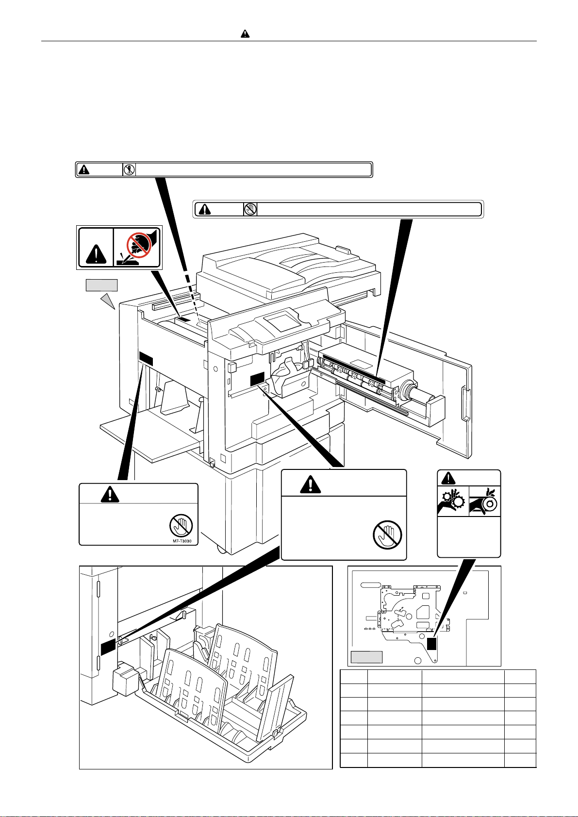
DLocations of warning stickers
The locations of the machine's warning stickers are shown below. To ensure safe work, read the
stickers and heed their instructions. Keep the stickers clean at all times. If they become damaged
or peel off, replace them with new ones.
No. Parts No. Name
Q'ty
q
L1-T3060 Warning Sticker 1
1
w
L5-T3020 Warning Sticker 2
2
e
r
M7-T3030
L8-T1090
Warning Sticker 3
Warning Sticker 4
1
1
View A
View A
M7-T3060
CAUTION
WARNING
Do NOT put hands inside machine
while it is operating.
Hands could get caught up
or crushed.
WARNING
● Do not remove this cover. The inside of the printer contains movable cutting instruments,
contact with which could result in injury.
L5-T3020
Do NOT touch the drum or rollers
when you operate the jog switch.
Do NOT put hands Inside
machine while it is operatung.
Hands could get caught up
or crushed.
WARNING
N5-T3010
Do not touch the roller below. Your clothes etc. may be stained with ink.
CAUTION
L8-T1090
WARNING
Use caution when working
near movable parts.
Disconnect power before
servicing.
q
t
y
e
w
r
y
N5-T3010
1

7
Chapter 8
Chapter 7
Chapter 6
Chapter 5
Chapter 4
Chapter 3
Chapter 2
Chapter 1
HELP Mode
Others
Troubleshooting
Maintenance / Check
Standard / Adjustment
Mechanism
Description of the Operation
Introduction


9
Table of Contents
Chapter 1
z Features................................................................................12
x Specifications ......................................................................14
c Dimensions ..........................................................................16
v System Setup.......................................................................18
b Part Names and Their Functions........................................19
n Operation Procedures.........................................................26
Chapter 2
z
Scanner Section.........................................................30
x
Platemaking/Master Feed/Ejection Section.............40
c
Paper Feed Section ...................................................66
v
Drum Driving Section................................................79
b
Press Section.............................................................85
n
Paper Ejection Section..............................................90
m
Drum Section .............................................................97
,
Option .......................................................................109
Chapter 3
z
Exterior .....................................................................112
x
Scanner Section.......................................................118
c
Platemaking/Master Feed/Ejection Section...........125
v
Paper Feed Section .................................................132
b
Drum Driving Section..............................................137
n
Paper Ejection Section............................................139
m
Drum Section ...........................................................144
Chapter 4
z
Scanner Section.......................................................154
x
Platemaking/Master Feed/Ejection Section...........156
c
Paper Feed Section .................................................164
v
Drum Driving Section..............................................169
b
Press Section...........................................................171
n
Paper Ejection Section............................................173
m
Drum Section ...........................................................175
,
Electrical System.....................................................179
.
Option .......................................................................188
Chapter 6
z
Troubleshooting Guide ...........................................194
x
Error Display ............................................................211
Chapter 7
Chapter 8
z
Electrical Parts Layout and Their Functions.........314
x
Overall Wiring Layout..............................................325
z
HELP Mode List .......................................................214
x
Overview...................................................................218
c HELP Mode Functions and Operation Procedures
.......219
(1)Accessing HELP Modes......................................219
(2)Guide to the HELP Mode Descriptions..............219
• HELP Mode Descriptions .....................................220
Introduction.................................................................................1
Using the service manual ..........................................................2
Safety instructions ...............................................................3
1.Cautions regarding the installation location........................3
2.Cautions for installation work...............................................4
3.Cautions for maintenance, inspection and servicing .........5
• Locations of warning stickers................................................6
Troubleshooting
Chapter 5
z
Guaranteed Periodical Maintenance......................190
x
Cleaning and Oiling.................................................190
c
Periodical Maintenance...........................................191
Maintenance / Check
Standards / Adjustment
HELP Mode
Others
Mechanism
Description of the Operation
Introduction


11
z Features........................................................................12
x Specifications...............................................................14
c Dimensions...................................................................16
v System Setup ...............................................................18
b Part Names and Their Functions................................19
1. Machine exteriors....................................................19
2. Sectional (structural) view of the machine ...........22
3. Control Panel ..........................................................24
n Operation Procedures .................................................26
1. Platemaking & Printing...........................................26
2. Multiple Image Printing / 2 IN 1 Layout Mode.......27
1
Chapter 1 Introduction

12
z Features
chap.1
zFeatures
Size A3/B4 printing(Printing area)
DP-460/440/430 : A3 ( 290X423mm )
DP-340/330/330L : B4 ( 250X355mm )
1.
High-speed platemaking2.
High print quality3.
Align paper4.
High-performance lamp5.
Simple operation6.
Full range of necessary functions
q
Documents are easily enlarged or reduced.
In addition to same-size printing, there are three
automatic settings for both enlargement and
reduction. Further, the margin (94% reduction)
function can be used for these automatic settings.
7.
• Zoom settings : (70, 81, 86, 115, 122, 141%)
• Same-size : (100%) printing
Size A/B models
• Free zoom : 50% -500% ( 1% )
Enlargement :141% [A4/A3, B5/B4]
*
4
122% [A4/B4, A5/B5]
115% [B4/A3, B5/A4]
*
4
Reduction : 86% [A3/B4, A4/B5]
*
4
81% [B4/A4, B5/A5]
70% [A3/A4, B4/B5]
*
4
*4:
Maximum printing area of DP-340 and DP-330
is B4(2509355mm).
• Zoom settings : (64, 74, 77, 121, 129, 141%)
• Same-size : (100%) printing
Inch size models
• Free zoom : 50% -500% ( 1% )
Enlargement :141%
129% [LTR/LDG]
121% [LGL/LDG]
Reduction : 77% [LGL/LTR]
*
5
74% [LDG/LGL]
*
5
67% [LDG/LTR]
*5:
Maximum printing area of DP-340 and DP-330
is 11"914"(2509355mm).
w
Self-diagnosis
The machines have self-diagnostic functions.
Messages for self-diagnosed errors, as well as
consumable part replacement prompt messages,
appear on an LCD panel.
e
Book shadow erasure
Shadows in the middle or at the edges of book
documents can be erased.
r
Adjusting the Printing Position(vertical)
In addition to vertical direction adjustment.
Print the first sheet of paper.(document size : A4R )
DP-460 : 24 seconds*
1
DP-440/340 : 19 seconds*
1
DP-430 : 24 seconds*
1
DP-330/330L : 23 seconds*
1
*1:Time required to print the first sheet of paper
after the platemaking key is pressed.
A new, originally-developed superfine thermal
head gives beautifully accurate reproductions of
fine print and halftone photographs.
Its resolution is 600dpi in the primary scanning
and 600dpi in the secondary scanning.
Its resolution is 400dpi in the primary scanning
and 400dpi in the secondary scanning.
Its resolution is 300dpi in the primary scanning
and 600dpi in the secondary scanning.
DP-430/330/330L
DP-440/340
DP-460
Adjusting the eject enables both thin and thick
sheets of paper to be aligned neatly.
A long-life, high-brightness xenon arc lamp is
used to illuminate the documents. Since the
lamp's intensity is not affected by temperature
variation*2, printing quality at low temperatures
is greatly enhanced*3.
*2: The lamp is filled with xenon gas, which means
that it does not require heat to vaporize mercury,
as a fluorescent lamp does, and therefore its
intensity does not vary with temperature.
*3: Increased viscosity of the ink at low temperatures
results in fainter printing than at normal
temperatures.
Operation is simplified by concealing
occasionally-used keys under a panel, leaving
just the basic function keys permanently
accessible.

13
z Features
chap.1
User setting
q
Memory Function
Equipped with a memory function (for 9
items) able to memorize frequently used
settings.
w
Optimize Print
Optimal images can be printed in times of
low/high temperature by setting the
temperature and the print speed.
e
Initial Paper Size setting
The paper size and print speed, etc., that
are valid when the power is turned on can
be set.
r
Document Memory
The last platemaking image can be
memorized, and used later for platemaking
without having to read it out again.
8.
Special functions
The HELP mode items listed below can now also be
used in the user mode. And the power save mode can
cut power consumption.
q
Fine Start
w
Auto Clear
e
Pre-print
r
Batch Print
t
Auto Power Off
y
Auto LCD Off
u
Long Paper mode
(OP: when mounting the long paper unit)
i
Ink Circulation
o
Tape Cluster ( tape inserter )
(OP: when mounting the tape cluster)
!0
Double Feed Detection
!1
Drum selection ( A3/A4 )
(OP: when mounting the A3/A4 drum unit)
9.
Option
q
S2-ADF
w
Drum unit
e
A3/A4 Drum unit
r
Tape Cluster
t
PC Interface kit 2
y
Key card counter 4
u
Postcard stacker
i
Long paper unit
10.
t
Document modes
The "Text-Photograph", "Text-Fine Lettering",
"Photograph-Fine Lettering", "Screen 1 & 2" and
"Photo Dark" Modes selecting, accommodating
printing of a wider variety of documents.
y
Adjusting the contrast control
The degree of contrast for printing can be
adjusted.

14
x Specifications
chap.1
xSpecifications
• Specifications
Model
Model name
DUPRINTER
DP-460 DP-440 DP-430 DP-340 DP-330 DP-330L
Floor model
Thermal digital master making
24 sec ( A4R 100% )
600dpi
19 sec ( A4R 100% )
400dpi
400dpi
19 sec ( A4R 100% )
24 sec ( A4R 100% )
300 dpix 600 dpi
23 sec ( A4R 100% )
300 dpix 600 dpi
Flat bed scanner
100 sheets (64 - 128gsm)
Stencil print
MAX. 297mm x 432mm
290mm x 423mm
290mm x 423mm (A3) (11.4"x16.6")
250mm x 355mm (B4) (9.8"x14") 8.3"x14" (LGL)
1,500 sheets(64gsm)
1,500 sheets (64gsm)
MAX: 297mm x 432mm
With Long paper unit (service part) : Max: 540mm
MIN: 100mm x 150mm
Master making method
Master making interval
Resolution
Scanning method
ADF (Optional)
Printing method
Sheets, book ( max: 10kg)Document type
Document size
Scanning area
Image area ( max)
Feeding capacity
Stacking capacity
Paper size
53gsm -210gsm (45kg-180kg)Paper weight
13lb - 110lb (Index)
Feeding pressure adj.( 3 steps )
Separator adj. ( 3 steps )
120 ppm ( 45-120 ppm, 5 steps) 130 ppm ( 45-130 ppm, 5 steps)
Print speed
100%Zoom A/B size
Inch size
Preset reduction/enlargement: 70, 81, 86, 115, 122, 141%
94%
Zoom: 50 - 500%
Auto zoom: 70, 81, 86, 115, 122, 141%
100%
Preset reduction/enlargement: 64, 74, 77, 121, 129, 141%
94%
Zoom: 50 - 500%
Auto zoom: 64, 74, 77, 121, 129, 141%
Vertical : +/- 15mm [ shown on the LCD by 0.5(mm)]Registration adjustment
Horizontal: +/- 10mm [shown on the LCD by 0.5(mm)]
Text,Photo,Text/Photo,Text Fine,Photo Fine,Screen1,Screen2,Photo DarkImage modes
Contrast control : Text mode, Photo mode, Text/Photo mode
Master making density: 5stepsContrast control
Print density: 11 steps
Automatic control (600ml, 1000ml)Ink supply method
Drum unit exchangeColour print
Roll master automatic feed Master feeding method
Automatic ejection/ master rolling-up method Master ejection method
50sheetsUsed master capacity
320 x 240 dot matrix full- dot matrix LCD ( with contrast control) LCD
OK monitor ( LCD graphic)
Remainig master display function, remainig master ejection display function
* Specifications are subject to change without notice.
+/- 5mm
(Within operating temperature)

x Specifications
chap.1
15
Other function
Model name
DUPRINTER DP-460/440/430/340 /330/330L
Image Rotation ( 90 & 180 degree)
Colour Separation (equipped in online printer driver)
Document Size Auto Scan
Multiple Exposure ( 2, 4, 8, & 16- up.)
Book Shadow Erasure ( adjustable)
Memory Function ( 9 pattern of settings of control panel can be stored.)
Confidential Safeguard
Initial setting (when the power is turned on.)
Optimize Print (
P-roller control according to user’s input of temperature and speed.
)
Online (IEEE1284 standard bi-directional parallel interface)
NB:For USB connection, optional interface kit II is required.
Document Memory , Auto Clear
Fine Start , Pre-print
Batch Print
Auto LCD Off
Auto Power Off
Ink Circulation
Double Feed Detection
S2-ADF [100sheets (64gsm)]Option
Drum unit
Tape inserter
PC interface kit II
Key card counter 4 ( built-in type)
Cabinet( with front door)
Cabinet( open )
Power source Domestic:100V +/- 10%, 50/60Hz, 3.0A
120V :120VAC60Hz, 2.5A
230V :230VAC50Hz, 1.3 A
250W(
during plate making
),230W(
during 3rd speed printing
),60W(
during standby
)Power consumption
In use: 1374mm(W) x 738mm(D) x 1089mm(H)Dimension
Folded: 753mm(W) x 738mm(D) x 1089mm(H)
With optional ADF attached:
In use: 1374mm(W) x 738mm(D) x 1228mm(H)
Folded: 753mm(W) x 738mm(D) x 1228mm(H)
119kgWeight
10 -30 degree(C)Operating temperature
Standard : Parallel bi-directional interfaceOnline
Confirmed with IEEE1284 (compatibility mode, nibble mode)
Printer driver must be installed in computer
[Windows95/98/Me, Windows NT4.0,Windows 2000/XP Professional/Home Edition]
Printer driver must be installed in computer
[Windows95/98/Me, Windows NT4.0,Windows 2000/XP Professional/Home Edition]
I/F PCB must be installed in the main unit.
* Specifications are subject to change without notice.
A3/A4 drum unit (Attachable to DP-460/440/430 only)
Optional : USB, SCSI interface (
PC interface kit II)
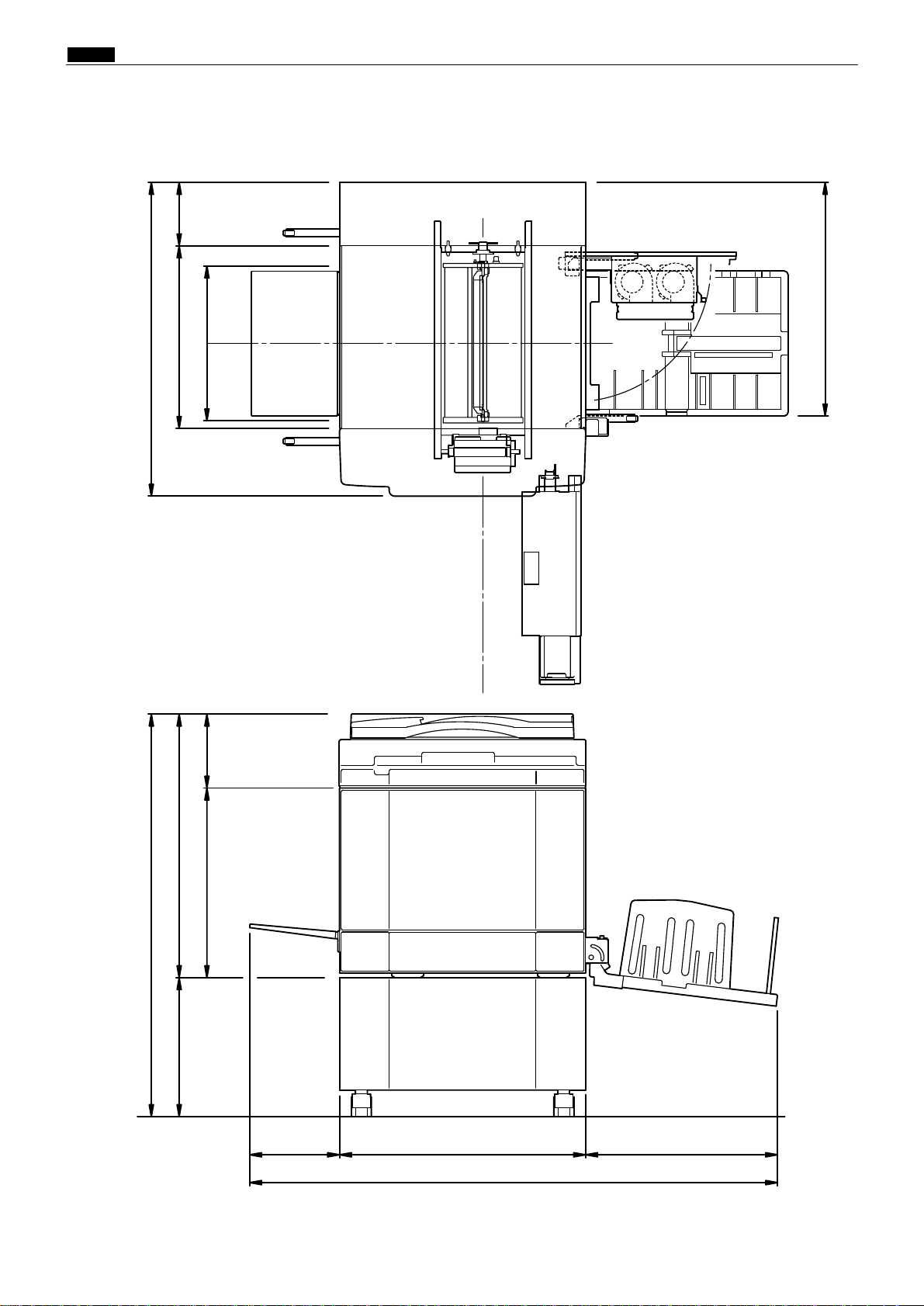
c Dimensions
chap.1
16
44000B
cDimensions
790.6
160
790.6
460
390
588.5
1013.9
664350
186.5477.5
226.5
483.5
620
1330
( mm )

c Dimensions
chap.1
17
MEMO

v System Setup
chap.1
18
vSystem Setup
1. Before Installation
The machine and its optional equipment are set up as follows:
Documents prepared on a personal computer can be printed on this machine.
The PC interface kit is required to connect this machine to a personal computer.
DDP system
NOTE :
KEYCARD COUNTER 4
: Option
TAPE CLUSTER 4
Cabinet (Printer stand)
Personal computer
S2-ADF
Duplo Direct Print System
Drum unit
A3/A4 drum (Attachable to DP-460/440/430 only)
44000C
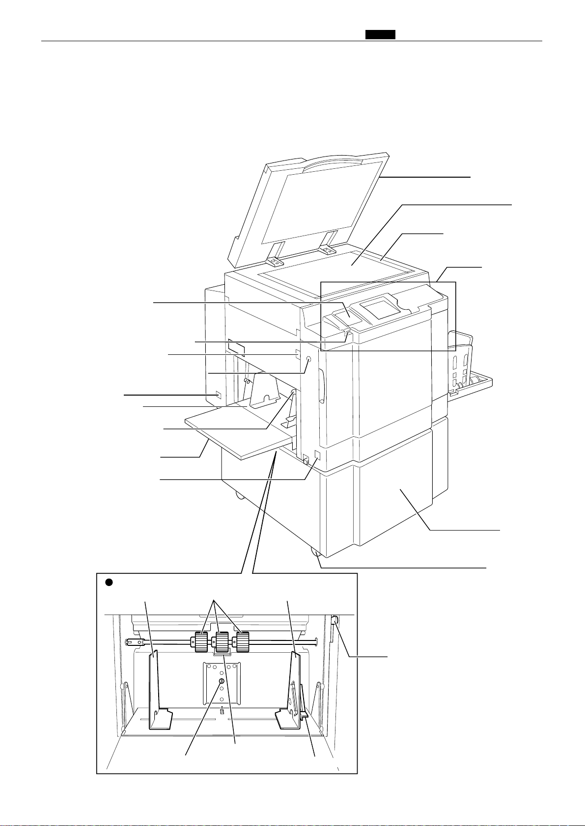
Panel cover
Contrast adjusting dial
Scanner switch
Feed tray descend switch
(Elevator down switch)
Inlet
Feed tray
Feed pressure
adjuster lever
Supplemental
paper tray
Power switch
Document cover
Glass
Vertical size scale plate
Control panel
Caster locks
Cabinet
(Optional)
Feed pressure adjuster lever
Feeder guide F
Paper feed roller
Feeder guide R
Paper separator unit
Paper feed section
Feeder guide lock leverSeparat pressure adjuster screw
b Part Names and Their Functions
chap.1
19
440AAe
bPart Names and Their Functions
1. Machine exteriors
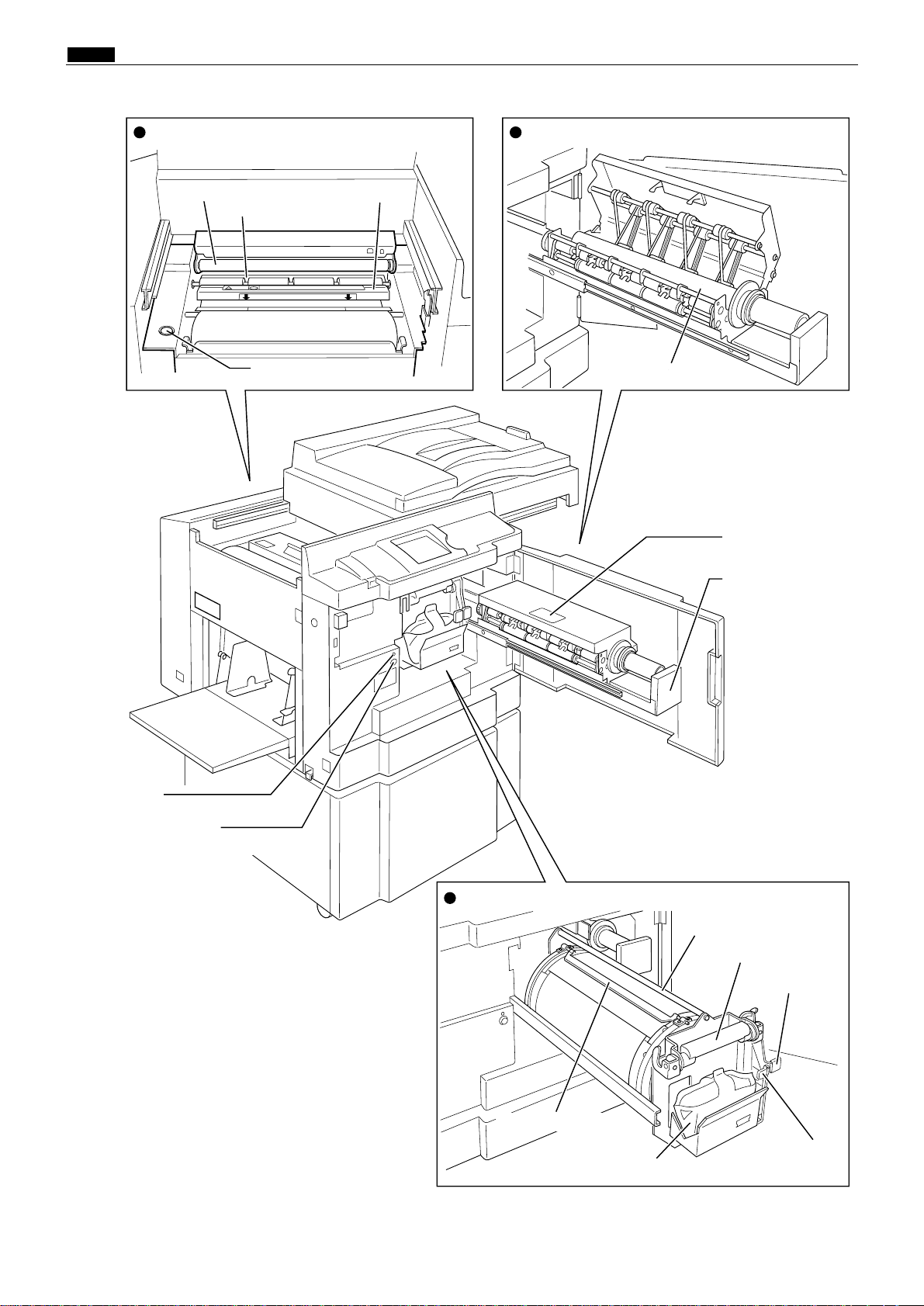
b Part Names and Their Functions
chap.1
20
Master ejection box
lid release lever
Master ejection box
lever
LED
JOG switch 1
(Drum rotator switch 1)
Master ejection core
Master ejection sectionMaster feed section
Drum bar
Drum handle
Drum securing
lever
Ink puck holder
release lever
Ink puck
Master clump
Drum section
Master roll cut switch
Cutter
Platen roller
Thermal head
440BBe
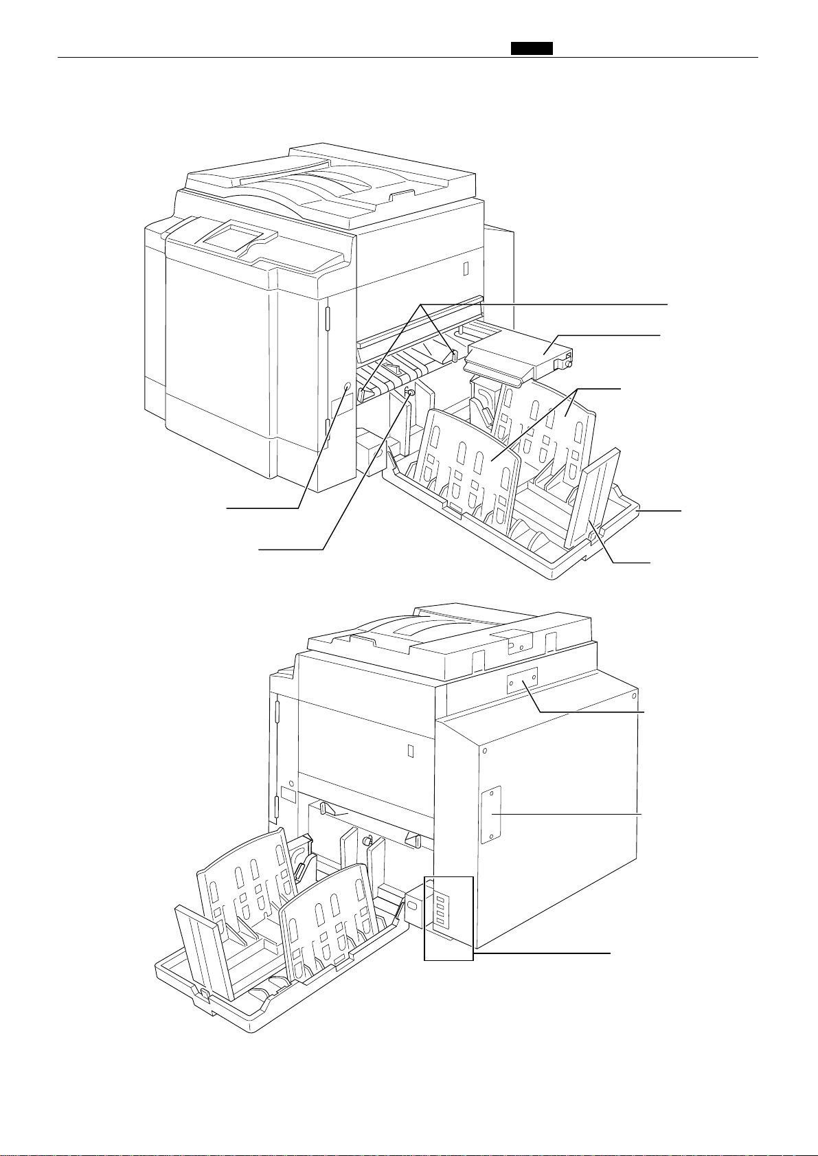
b Part Names and Their Functions
chap.1
21
JOG switch 2
(Drum rotator switch 2)
Paper aligning lever
Jump plate
Top blow fun
Paper stacker guide
Paper stopper
S2-ADF
connector cover
(Optional)
Interface kit II
(Optional)
Connectors (Optional)
Print tray
440CCe
b Part Names and Their Functions
chap.1
22
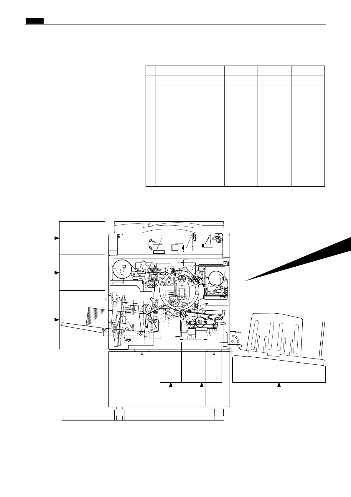
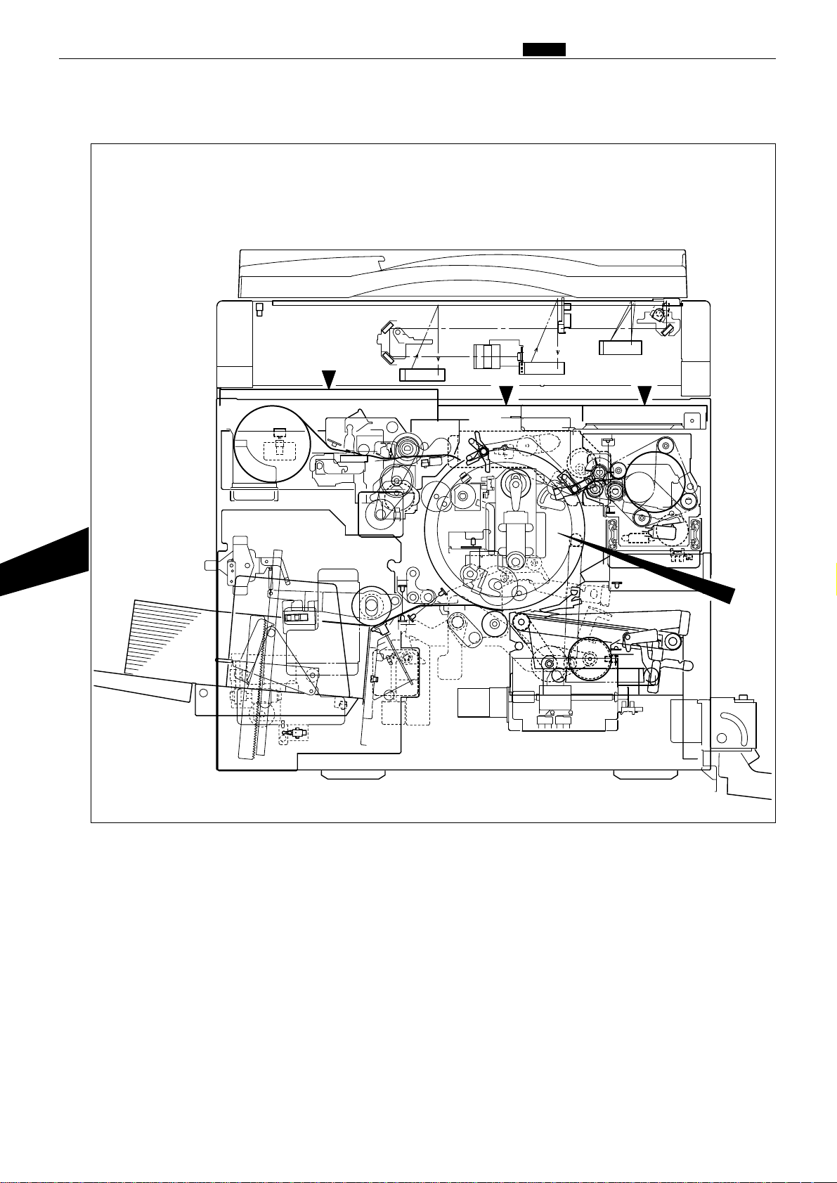
2. Sectional (structural) view of the machine
1
2
3
56 7
No.
1
2
2A
2B
2C
3
4
5
6
7
8
Section Name
Scanner section
Platemaking/Master feed/ejection section
Platemaking/Master feed section
Master ejection section
Master clamp opening/closing section
Paper feed section
Drum driving section
Press section
Paper ejection section
Print tray
Drum section
30page
40page
40page
52page
54page
66page
79page
85page
90page
4
97page
Mechanism
118page
125page
125page
129page
130page
132page
137page
4
139page
4
144page
Srandard/Adjustment
154page
156page
156page
157page
159page
164page
169page
171page
173page
4
175page
Description of
the Operation
44000Ae
4,8
2A
2B
2C
44000A1e
b Part Names and Their Functions
chap.1
23
b Part Names and Their Functions
chap.1
24
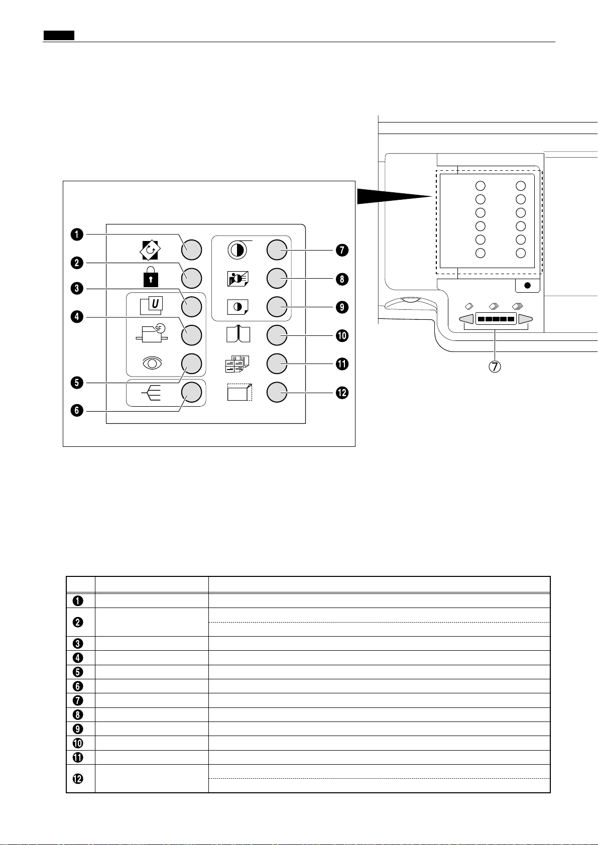
3. Control Panel
EDIT key
NameNo. Function
Switches to rotate the document image for plate.
CONFIDENTIAL SAFEGUARD key
Enables confidential safeguard function.
Prints cannot be made unless a new master is made.
USER SETTING key Switches to User setting list display.
SPECIAL FUNCTION key
Switches to Special function list display.
CURRENT SETTING key
Shows a list of current setting of the machine.
SORTER MODE key Switches to sorter mode display.
MASTER DARKNESS key
Switches to Master darkness control display.
MASTER CONTRAST key
Switches to Master contrast control display.
PRINT DARKNESS key Switches to Print Darkness control display.
BOOK SHADOW ERASURE key
Switches to Book Shadow erasure setting display.
MULTIPLE EXPOSURE key
Switches to multiple exposure setting display.
94% key
Reduces image to 94%.
94% key can be used in conjunction with preset zoom setting.
94 %
2Keys inside of the panel cover
b Part Names and Their Functions
chap.1
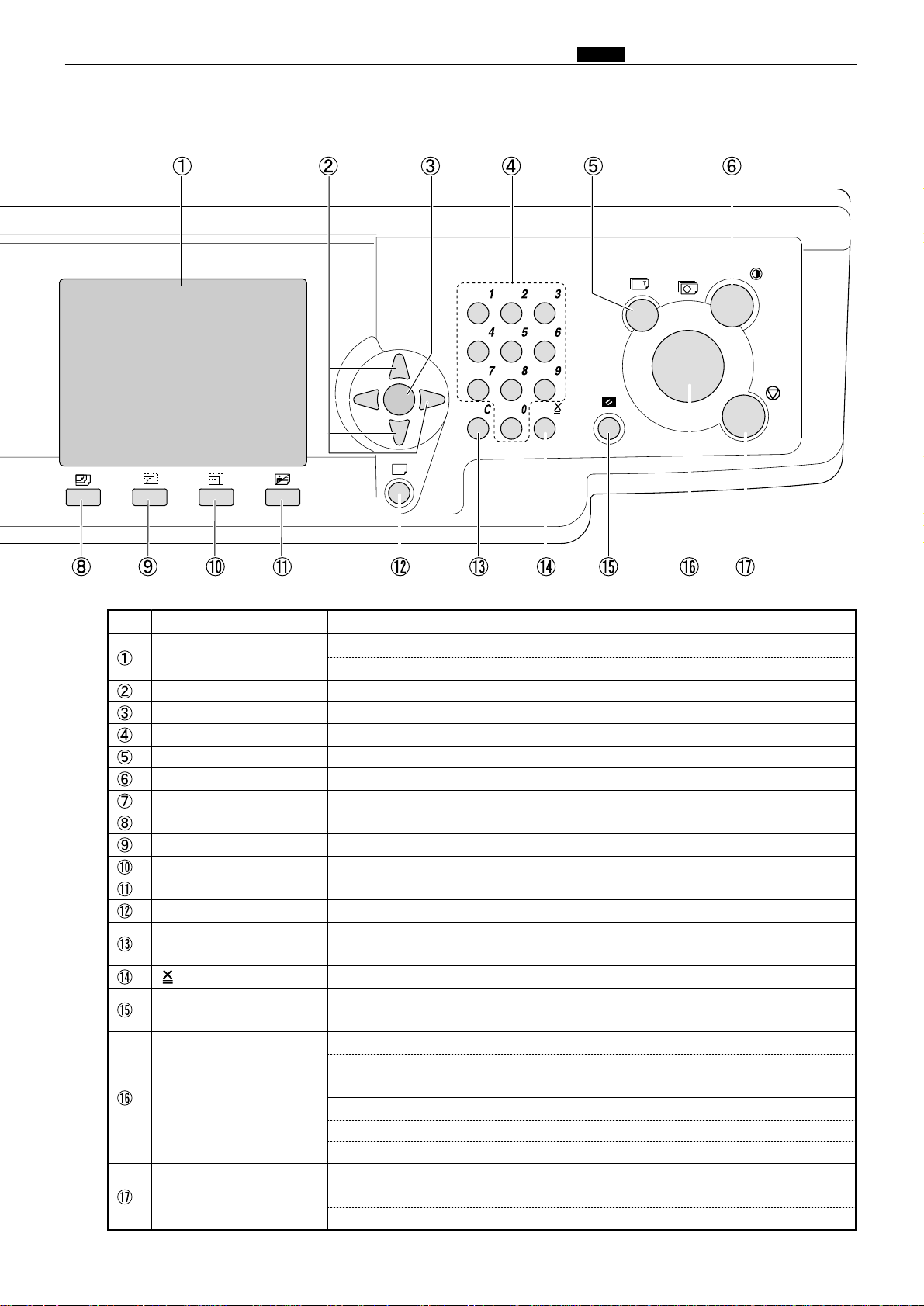
25
LCD
NameNo. Function
Displays current settings and status of the machine e.g. print volume,
and error messages in case of error.
Cursor keys Selects setting item and adjusts printing position.
OK key Enters specified setting.
Ten keys Enter the print volume etc.
TEST PRINT key Prints 1 copy to check the image position and density etc.
PLATE MAKING key Starts making a master.
PRINT SPEED key Switches to Print speed control display.
PAPER SIZE key Switches to Paper size selection display.
ZOOM key Switches to Zoom setting display.
PRINT POSITION key Switches to Print Position control display.
IMAGE MODE key Switches to image mode selection display.
CANCEL key
Cancels settings in Special Functions etc and returns to main display.
CLEAR key
Returns the print volume to 0.
Other settings on the control panel are not changed.
key Enters the print and group number in batch printing.
ALL CLEAR key
Return all settings on the control panel to default.
( Press and hold at least 1 second.)
PRINT key
Starts printing. This key does not start making a master.
Printing cannot start when the lamp o the key is red.
Confirm that the light is Blue before pressing.
When equipped with optional ADF unit:
When next document is set on the ADF, next master making starts automatically
after a printing is finished.
STOP key
Stops printing.
*While the machine is not working, indicates the total print quantity
and the total master quantity.
n Operation Procedures
chap.1
26
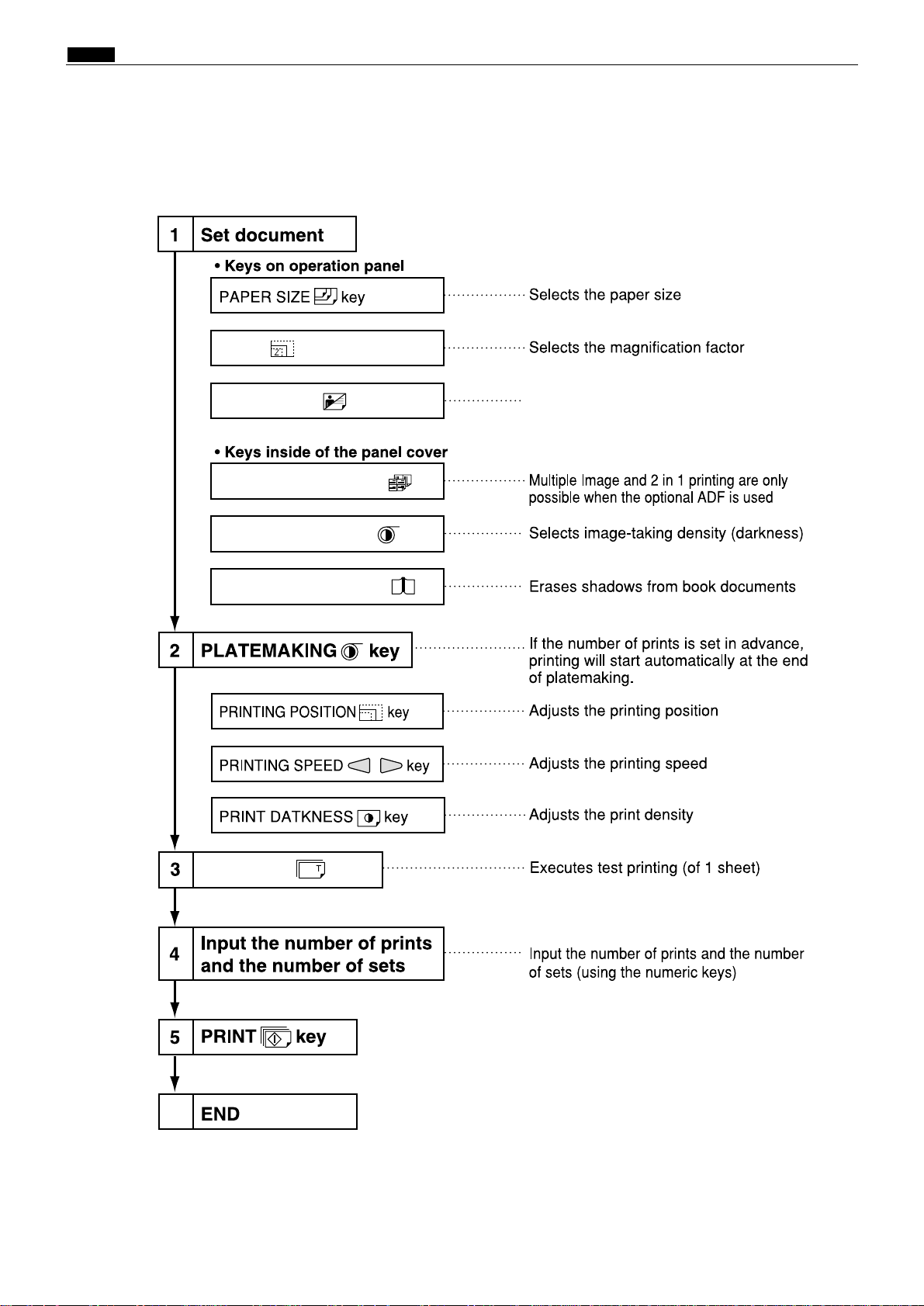
nOperation Procedures
1. Pratemaking & Printing
ZOOM key
IMAGE MODE key
MULTIPLE EXPOSURE key
MASTER DARKNESS key
TEST PRINT key
6
BOOK SHADOW ERASER key
Selects Text , Photograph ,
Text / Photograph Mode
n Operation Procedures
chap.1
27
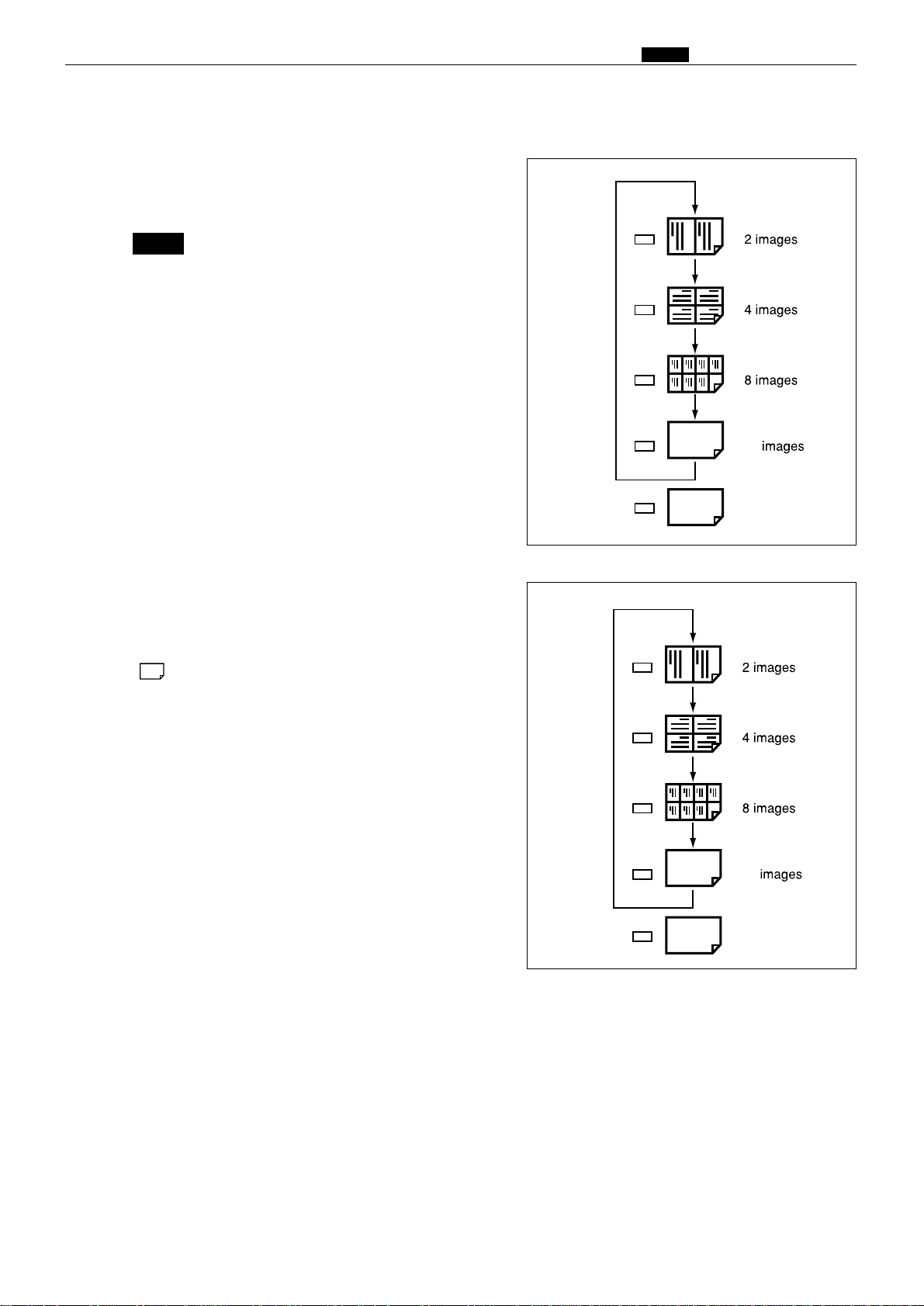
2. Multiple Image Printing / 2 IN 1 Layout Mode
In the normal state (when the ADF is not connected) the
mode is switched by pressing the multiple printing
selection key as follows.
Each press of the multiple printing selection key
makes a different multiple printing indicator
light up, in sequence.
To set the number of images, press the key until
the indicator for the desired number of images
is lit.
2in1
16
NOTE :
When the ADF is connected, the multiple printing selection
key can also be used to select the 2 in 1 Layout Mode, as
shown below.
To activate the 2 in 1 Layout Mode, press the key until the
" " icon is lit.
2in1
16
2in1

28
Chapter 2 Description of the Operation
z Scanner Section...........................................................30
1. Description...............................................................30
2. Sequence of Operation...........................................31
(1) Sequence of the Scanner Operation ..................31
(2) Sequence of the Scanner Operation (ADF).......31
(3) Operation with the Document
Cover Open / Closed ..........................................32
1. Reading the Document Size...........................32
2. Reading the Document Darkness..................32
2
Platemaking Area for the Selected Paper.....33
2
Platemaking Area for the Book Shadow
Erasing Mode..................................................33
3. Function of Parts and Circuit.............................34
(1) Home Position Sensors ......................................34
(2) Document Sensor ..............................................35
(3) Document Cover Sensor.....................................37
(4) CCD / Lamps ......................................................38
(5) Scanner Unit Open / Close Detection................39
x Platemaking / Master Feed / Ejection Section...........40
Platemaking /
Master Feed Section
........................40
1. Description...............................................................40
2. Sequence of Operation...........................................41
(1) Operation when the master set ........................41
(2) Platemaking / Master Feeding ..........................42
3. Function of Parts ....................................................43
(1) Thermal Head.....................................................43
(2) End Mark Sensor ...............................................46
1. Master Setting Error Detection......................47
2. Master End Detection......................................47
(3) Master top sensor...............................................48
(4)
Master Detect Sensor ........................................49
(5) Cutter Unit.........................................................50
(6)
Master Feed Clutch (Electromagnetic clutch)..51
Master Ejection Section ...........................................52
1. Description...............................................................52
2. Circuit.......................................................................52
3. Function of Parts ....................................................53
(1) Master Ejection Sensor......................................53
1. Master Ejection Error Detection.....................53
2.
Rotation Control of the Eject(Roll-up) Motor
.........53
Master Clamp Opening/Closing Section ...............54
1. Description...............................................................54
2.
Operation of Master Clamp Open / Close Lever
........55
(1) Structure.............................................................55
(2) Master Attach / Detach Operation....................56
(3) Clamp Opening / Closing
Lever Position (A / B / C Mode) .........................57
3. Function of Parts ....................................................58
(1) A / B / C Mode Detect Sensor.............................58
4. Returning Operation Flowchart
When the Power is Cut Off Accidentally...............59
Master Clamp Opening/Closing Section ...............60
1. Description...............................................................60
2.
Operation of Master Clamp Open / Close Lever
........61
(1) Structure.............................................................61
(2) Master Attach / Detach Operation....................62
(3) Clamp Opening / Closing
Lever Position (B / C Mode)...............................63
3. Function of Parts ....................................................64
(1) B / C Mode Detect Sensor ..................................64
4. Returning Operation Flowchart
When the Power is Cut Off Accidentally...............65
Product No.: initial lot - 020455313
Product No.: 020455314 -

29
2
c Paper Feed Section .....................................................66
1. Description...............................................................66
2. Operation .................................................................67
(1) Rotation of the Paper Feed Roller and
Timing Roller.....................................................67
(2) Paper Feed Roller Drive.....................................68
(3) Driving of the Timing Roller..............................69
(4) Escape the Guide Roller.....................................70
(5) Paper Feed Length.............................................71
3. Function of Parts.....................................................72
(1) Printing Position Adjustment Mechanism .......72
(2) Double Feed Detect Mechanism........................74
(3) Elevator Top Limit Sensor.................................75
(4) Elevator Lower Limit Switch ............................76
(5) Paper Sensor.......................................................77
(6) Elavator Encoder Sensor ..................................78
(7) Long Paper Unit Mechanism( Option ) ............78
v Drum Driving Section ..................................................79
1. Description...............................................................79
2. Function of Parts ....................................................80
(1) Drum Stop / JAM Detect Position Sensor.........80
(2) Master Attach / Detach Position Sensor...........81
(3) JOG Switch 1,2(Drum Rotation Switch 1,2).....82
(4) Control of the Main Motor.................................83
1. Rotation Speed Control by Encoder Sensor ...84
2. Selecting the Speed..........................................84
b Press Section ...............................................................85
1. Description...............................................................85
(1) Press Roller Timing & Printing Area................85
2. Function of Parts ....................................................87
(1) P-Roll Sensor......................................................87
(2) Switching the Contact Pressure........................88
1. Contact pressure position sensing..................89
n Paper Ejection Section................................................90
1. Description...............................................................90
2. Function of Parts ....................................................91
(1) Paper Stripper Finger........................................91
(2) Top Blow Fan......................................................92
(3) Paper Ejection Jam Sensor ...............................93
1. Paper JAM Detection Timing .........................94
(4) Paper Ejection Belt ............................................95
1. Paper ejection belt speed.................................95
(5) Paper aligning mechanism ................................96
m Drum Section ...............................................................97
1. Description...............................................................97
2. Circuit.......................................................................98
3. Function of Part.......................................................99
(1) Ink Detection......................................................99
1. LED Display and Output Signal on
the Ink Detection PCB Unit..........................100
2. "CHANGE INK" Display Timing..................101
(2) Ink Roller Up / Down Mechanism...................102
(3) Ink Pump..........................................................104
(4) Drum Switch.....................................................105
(5) Fine Start Mode................................................106
(6) Drum Shift Mechanism....................................107
(7) Front Cover Detection Switch .........................108
, Option .........................................................................109
(1) TAPE CLUSTER..............................................109
 Loading...