

Duplo DUPRINTER DP-440, DUPRINTER DP-430, DUPRINTER DP-340, DUPRINTER DP-330 Service Manual
Page 1

Page 2

Page 3

1
Introduction
The cause of most accidents is failure to adhere to basic safety rules and observe
safety instructions. It is important to prevent potential causes of accidents from
occurring. In order to do so, read this manual carefully, and be sure to understand
all the safety instructions and correct inspection and servicing procedures that it
provides before beginning repair or servicing work.
Repairing or servicing the machine with insufficient knowledge about it could
lead to unforeseen accidents.
It is not possible to anticipate and describe in a manual such as this every possible hazard that could arise in the course of repair and servicing. Therefore, besides
observing the safety instructions marked in this manual and on the machine's
labels, service personnel should be safety-conscious and take other safety precautions as necessary. When performing repair or service work not covered by this manual, you should obtain safety guidance from an appropriately knowledgeable person.
Copyright 2002
DUPLO SEIKO CORPORATION
All Rights Reserved
Page 4

2
'Safety-related instructions
If the instructions accompanying this symbol are ignored and the
machine is operated incorrectly, death or serious injury is likely to
result.
If the instructions accompanying this symbol are ignored and the
machine is operated incorrectly, death or serious injury, or else material
damage, is likely to result.
WARNING:
CAUTION:
Examples of pictorial symbols
A " " symbol tells you that a certain action is forbidden. Precisely what
is forbidden is indicated by a picture inside the symbol (in the example
here, the picture means that disassembly is forbidden), or in writing at the
side of the symbol.
A " " symbol means that a certain action is forbidden and/or that a
specific instruction must be followed. The specific instruction is indicated
by a picture inside the symbol (in the example here, the instruction is
"Remove the power plug from the socket").
IMPORTANT:
NOTE:
Draws attention to important information. If this information is ignored
and the machine is operated or serviced incorrectly, the machine`s
performance could drop, or it could break down.
Draws attention to information that is useful for operation or maintenance
of the machine, and to information about its performance, etc.
D Using the service manual
• This manual contains the following information: structure and function of major parts,
disassembly and reassembly procedures, specifications, and procedures for adjustment,
maintenance, inspection and corrective action. This information is current as of January
2002, and applies basically to the model DP-440/DP-430/DP-340/DP-330 DUPRINTER.
From time to time, parts are changed to improve quality, performance or safety. Note therefore
that in some cases, certain parts or machine structure aspects described in the text or
illustrations of this manual may not be precisely the same as the product being serviced.
• Safety instructions marked with a " " (WARNINGS and CAUTIONS) are very important for
safety and must be observed.
Page 5

3
Safety instructions
Safety instructions
Safety instructions
1. Cautions regarding the installation location
Installation environment
s Avoid installing the machine in places exposed to direct sunlight.
• Sunlight will cause the temperature in the machine's interior to rise, possibly leading to
malfunction of the control system.
• Sunlight could cause misoperation of the sensors.
• The heat of direct sunlight could cause deformation of the machine's plastic parts.
* Also avoid installation near to a ground glass window; light and heat penetrate such windows
although they are opaque.
s Avoid installing the machine in places subject to high or low temperature or humidity.
• High or low temperature or humidity could cause the machine to operate abnormally.
Suitable temperature and humidity ranges are:
Ambient temperature: 10y430y
Ambient humidity: 40%470%
Optimum temperature and humidity: 20y, 65%
• If the machine is installed near to faucets, water heaters or humidifiers, or in cool (sunless)
parts of a building or in the vicinity of water sources, the paper could absorb moisture and curl,
leading to misfeeds or poor image quality.
s Avoid installing the machine in places with open flames, or where reflected heat or other hot air
currents (from stoves, etc), or cold air currents from coolers, etc will strike it directly.
s Avoid installing the machine in poorly ventilated places.
s Avoid installing the machine in dusty places.
s The machine should not be tilting when it is used.
• Install the machine so that it is level.
(The machine should be level to within 5mm in the front-rear direction, and 5mm in the lateral
direction.)
sDo not install the machine on shaky, sloping or otherwise unstable surfaces.
• The machine could fall over on such surfaces, or fall off them, causing injury.
Page 6

4
Safety instructions
Warning
• The machine's power supply voltage and power consumption depend on the model. Details of this
are given in the tables below. The power supply voltage and power consumption for the machine
are given in the table below. The machine's power supply voltage is indicated on the identification
plate located on the machine's left side; the machine must be connected to a power supply of the
voltage indicated.
a Otherwise, fire or electric shock could result.
If the power supply voltage is unstable or if the power supply has insufficient capacity, the
machine may not operate normally.
Make sure that the power supply has sufficient capacity for the system as a whole, including
optional equipment.
Connect to outlet of 120V AC, 60Hz, at least 15A
With no load*
At full load
Power consumption
No more than 130V AC
At least 110V AC
During platemaking : 250W
During printing at speed 3 (printing speed) :230W
On standby : 60W
Power supply voltage
}
Use power supply meeting these requirements
Connect to outlet of 230V AC, 50Hz, at least 8A
With no load*
At full load
Power consumption
No more than 250V AC
At least 210V AC
During platemaking : 250W
During printing at speed 3 (printing speed) :230W
On standby : 60W
Power supply voltage
}
Use power supply meeting these requirements
* 120V AC model
* 230V AC model
* "With no load" - when the machine is on standby.
* "At full load" - when the machine is running at maximum power consumption.
• Use only the power cord that is provided among the accessories.
Insert the power cord plug firmly into the socket, so that proper electrical contact is effected.
• Install the machine close to its power supply. The outlet used should be exclusively for the
machine, and have no other equipment connected to it.
If an extension cord is necessary, it should have a ground terminal, and be of the following ratings:
* For a 120V AC model: 130V, at least 15A, length not exceeding 5m.
* For a 230V AC model: 250V, at least 8A, length not exceeding 5m.
• Never tread on the power cord or pinch it between other objects, or accidents could result.
2. Cautions for installation work
• Install the machine in accordance with the installation procedure appended to this manual.
• Lock the casters after the machine is installed.
a Otherwise, the machine could move or fall over, causing injury.
• To move the machine, push it by its mounting base.
a Pushing the printing (upper) part of the machine could make it fall over.
CAUTION
Using the optional printer stand
Page 7

5
Safety instructions
' Precautions for safe servicing
• Always remove the power cord plug from the outlet before starting work.
a Otherwise, you could get a shock or your hands/fingers could be injured.
• However, the plug must be left connected to the outlet when performing function checks (of
individual motors, a given series of operations, or electrical circuits). When motors are
operated alone in function checks, interlocks are deactivated, so be aware of the conditions and
positions of related equipment, and take great care not to put your hands or fingers into
moving parts.
• The cutter unit contains hazardous sharp blades. Exercise great care when inspecting the cutter
unit or replacing it or its parts.
a Otherwise, your hands/fingers could be injured.
• Do not touch the drum or rollers after turning on the jog switch.
• Do not put your hands or fingers inside the machine while the drum is rotating.
a Otherwise, your hands/fingers could get caught and crushed between the drum and rollers.
' Working clothes
• Wear clothing than enables you to work safely.
Warning
' Tools
• Use tools that are appropriate for the work.
CAUTION
3. Cautions for maintenance, inspection and servicing
• The tape clusters have hazardous blades. Exercise care when inspecting or replacing the
blades.
a Otherwise, your hands/fingers could be injured.
If optional tape clusters are used
Page 8

6
Safety instructions
DLocations of warning stickers
The locations of the machine's warning stickers are shown below. To ensure safe work, read the
stickers and heed their instructions. Keep the stickers clean at all times. If they become damaged
or peel off, replace them with new ones.
No. Parts No. Name
Q'ty
q
L1-T3060 Warning Sticker 1
1
w
L5-T3020 Warning Sticker 2
2
e
r
M7-T3030
M7-T3060
Warning Sticker 3
Caution Sticker 1
1
1
M7-T3060
CAUTION
WARNING
Do NOT put hands inside machine
while it is operating.
Hands could get caught up
or crushed.
WARNING
● Do not remove this cover. The inside of the printer contains movable cutting instruments,
contact with which could result in injury.
L5-T3020
Do NOT touch the drum or rollers
when you operate the jog switch.
Do NOT put hands Inside
machine while it is operatung.
Hands could get caught up
or crushed.
WARNING
N5-T3010
Do not touch the roller below. Your clothes etc. may be stained with ink.
CAUTION
t
N5-T3010
Caution Sticker 2 1
q
r
t
e
w
Page 9

7
Chapter 8
Chapter 7
Chapter 6
Chapter 5
Chapter 4
Chapter 3
Chapter 2
Chapter 1
HELP Mode
Others
Troubleshooting
Maintenance / Check
Standard / Adjustment
Mechanism
Description of the Operation
Introduction
Page 10

9
Table of Contents
Chapter 1
z Features................................................................................12
x Specifications ......................................................................14
c Dimensions ..........................................................................16
v System Setup.......................................................................18
b Part Names and Their Functions........................................19
n Operation Procedures.........................................................26
m Option...................................................................................28
Chapter 2
z
Scanner Section.........................................................32
x
Platemaking/Master Feed/Ejection Section.............42
c
Paper Feed Section ...................................................62
v
Drum Driving Section................................................75
b
Press Section.............................................................81
n
Paper Ejection Section..............................................86
m
Drum Section .............................................................93
,
Option .......................................................................105
Chapter 3
z
Exterior .....................................................................108
x
Scanner Section.......................................................114
c
Platemaking/Master Feed/Ejection Section...........120
v
Paper Feed Section .................................................127
b
Drum Driving Section..............................................132
n
Paper Ejection Section............................................134
m
Drum Section ...........................................................139
Chapter 4
z
Scanner Section.......................................................148
x
Platemaking/Master Feed/Ejection Section...........150
c
Paper Feed Section .................................................158
v
Drum Driving Section..............................................163
b
Press Section...........................................................165
n
Paper Ejection Section............................................167
m
Drum Section ...........................................................169
,
Electrical System.....................................................173
.
Option .......................................................................182
Chapter 6
z
Troubleshooting Guide ...........................................188
x
Error Display ............................................................205
Chapter 7
Chapter 8
z
Electrical Parts Layout and Their Functions.........298
x
Overall Wiring Layout..............................................309
z
HELP Mode List .......................................................208
x
Overview...................................................................212
c HELP Mode Functions and Operation Procedures
.......213
(1)Accessing HELP Modes......................................213
(2)Guide to the HELP Mode Descriptions..............213
• HELP Mode Descriptions .....................................214
Introduction.................................................................................1
Using the service manual ..........................................................2
Safety instructions ...............................................................3
1.Cautions regarding the installation location........................3
2.Cautions for installation work...............................................4
3.Cautions for maintenance, inspection and servicing .........5
• Locations of warning stickers................................................6
Troubleshooting
Chapter 5
z
Guaranteed Periodical Maintenance......................184
x
Cleaning and Oiling.................................................184
c
Periodical Maintenance...........................................185
Maintenance / Check
Standards / Adjustment
HELP Mode
Others
Mechanism
Description of the Operation
Introduction
Page 11

11
z Features........................................................................12
x Specifications...............................................................14
c Dimensions...................................................................16
v System Setup ...............................................................18
b Part Names and Their Functions................................19
1. Machine exteriors....................................................19
2. Sectional (structural) view of the machine ...........22
3. Control Panel ..........................................................24
n Operation Procedures .................................................26
1. Platemaking & Printing...........................................26
2. Multiple Image Printing / 2 IN 1 Layout Mode.......27
m Option ...........................................................................28
1. DUPRINTER Option.................................................28
(1) TAPE CLUSTER 4.............................................28
1
Chapter 1 Introduction
Page 12

12
z Features
chap.1
zFeatures
Size A3/B4 printing(Printing area)
DP-440/DP-430 : A3 ( 290X423mm )
DP-340/DP-330 : B4 ( 250X355mm )
1.
High-speed platemaking2.
High print quality3.
Align paper4.
High-performance lamp5.
Simple operation6.
Full range of necessary functions
q
Documents are easily enlarged or reduced.
In addition to same-size printing, there are three
automatic settings for both enlargement and
reduction. Further, the margin (94% reduction)
function can be used for these automatic settings.
7.
• Zoom settings : (70, 81, 86, 115, 122, 141%)
• Same-size : (100%) printing
Size A/B models
• Free zoom : 50% -500% ( 1% )
Enlargement :141% [A4/A3, B5/B4]
*
4
122% [A4/B4, A5/B5]
115% [B4/A3, B5/A4]
*
4
Reduction : 86% [A3/B4, A4/B5]
*
4
81% [B4/A4, B5/A5]
70% [A3/A4, B4/B5]
*
4
*4:
Maximum printing area of DP-340 and DP-330
is B4(2509355mm).
• Zoom settings : (64, 74, 77, 121, 129, 141%)
• Same-size : (100%) printing
Inch size models
• Free zoom : 50% -500% ( 1% )
Enlargement :141%
129% [LTR/LDG]
121% [LGL/LDG]
Reduction : 77% [LGL/LTR]
*
5
74% [LDG/LGL]
*
5
67% [LDG/LTR]
*5:
Maximum printing area of DP-340 and DP-330
is 11"914"(2509355mm).
w
Self-diagnosis
The machines have self-diagnostic functions.
Messages for self-diagnosed errors, as well as
consumable part replacement prompt messages,
appear on an LCD panel.
e
Book shadow erasure
Shadows in the middle or at the edges of book
documents can be erased.
r
Adjusting the Printing Position(vertical)
In addition to vertical direction adjustment.
Print the first sheet of paper.(document size : A4 )
DP-440/DP-340: 21 seconds*
1
DP-430/DP-330: 27 seconds*
1
*1:Time required to print the first sheet of paper
after the platemaking key is pressed.
A new, originally-developed superfine thermal
head gives beautifully accurate reproductions of
fine print and halftone photographs.
Its resolution is 400dpi in the pel path direction
and 400dpi in the line progression direction.
Its resolution is 300dpi in the pel path direction
and 600dpi in the line progression direction.
DP-430/DP-330
DP-440/DP-340
Adjusting the eject enables both thin and thick
sheets of paper to be aligned neatly.
A long-life, high-brightness xenon arc lamp is
used to illuminate the documents. Since the
lamp's intensity is not affected by temperature
variation*2, printing quality at low temperatures
is greatly enhanced*3.
*2: The lamp is filled with xenon gas, which means
that it does not require heat to vaporize mercury,
as a fluorescent lamp does, and therefore its
intensity does not vary with temperature.
*3: Increased viscosity of the ink at low temperatures
results in fainter printing than at normal
temperatures.
Operation is simplified by concealing
occasionally-used keys under a panel, leaving
just the basic function keys permanently
accessible.
Page 13

13
z Features
chap.1
User setting
q
Memory Function
Equipped with a memory function (for 9
items) able to memorize frequently used
settings.
w
Optimize Print
Optimal images can be printed in times of
low/high temperature by setting the
temperature and the print speed.
e
Initial Paper Size setting
The paper size and print speed, etc., that
are valid when the power is turned on can
be set.
r
Document Memory
The last platemaking image can be
memorized, and used later for platemaking
without having to read it out again.
8.
Special functions
The HELP mode items listed below can now also be
used in the user mode. And the power save mode can
cut power consumption.
q
Sorter Fine Start
w
Auto Clear
e
Pre-print
r
Batch Print
t
Auto Power Off
y
Auto LCD Off
u
Long Paper mode
i
Ink Circulation
o
Tape Cluster ( tape inserter )
!0
Double Feed Detection
!1
Drum selection ( A3/A4 )
9.
Option
q
S2-ADF
w
Drum unit
e
A3/A4 Drum unit
r
Tape Cluster
t
PC Interface kit 2
y
Key card counter 4
u
Postcard stacker
i
Long paper unit
o
Sorter
10.
t
Document modes
The "Text-Photograph", "Text-Fine Lettering",
"Photograph-Fine Lettering", "Screen 1 & 2" and
"Photo Dark" Modes selecting, accommodating
printing of a wider variety of documents.
y
Adjusting the contrast control
The degree of contrast for printing can be
adjusted.
Page 14

14
x Specifications
chap.1
xSpecifications
• Specifications
Model
Model name
DUPRINTER
DP-440
DUPRINTER
DP-430
DUPRINTER
DP-340
DUPRINTER
DP-330
Floor model
Thermal digital master making
21 sec ( A4 100% )
400dpi
400dpi
21 sec ( A4 100% )27 sec ( A4 100% ) 27 sec ( A4 100% )
300 dpix 600 dpi 300 dpix 600 dpi
Flat bed scanner
100 sheets (64 - 128gsm)
Stencil print
MAX. 297mm x 432mm
290mm x 423mm
290mm x 423mm (A3) (11.4"x16.6") 250mm x 355mm (B4) (9.8"x14")
1,500 sheets(64gsm)
1,500 sheets (64gsm)
MAX: 297mm x 432mm
With Long paper unit (service part) : Max: 540mm
MIN: 100mm x 150mm
Master making method
Master making interval
Resolution
Scanning method
ADF (Optional)
Printing method
Sheets, book ( max: 10kg)Document type
Document size
Scanning area
Image area ( max)
Feeding capacity
Stacking capacity
Paper size
53gsm -210gsm (45kg-180kg)Paper weight
13lb - 110lb (Index)
Feeding pressure adj.( 3 steps )
Separator adj. ( 3 steps )
120 ppm ( 45-120 ppm, 5 steps)
Within operating temperaturePrint speed
100%Zoom A/B size
Inch size
Preset reduction/enlargement: 70, 81, 86, 115, 122, 141%
94%
Zoom: 50 - 500%
Auto zoom: 70, 81, 86, 115, 122, 141%
100%
Preset reduction/enlargement: 64, 74, 77, 121, 129, 141%
94%
Zoom: 50 - 500%
Auto zoom: 64, 74, 77, 121, 129, 141%
Vertical : +/- 15mm [ shown on the LCD by 0.5(mm)]Registration adjustment
Horizontal: +/- 10mm [shown on the LCD by 0.5(mm)]
Text,Photo,Text/Photo,Text Fine,Photo Fine,Screen1,Screen2,Photo DarkImage modes
Contrast control : 5steps
Master making density: 5 steps Contrast control
Print density: 11 steps
Automatic control (600ml, 1000ml)Ink supply method
Drum unit exchangeColour print
Roll master automatic feed Master feeding method
Automatic ejection/ master rolling-up method Master ejection method
50sheetsUsed master capacity
320 x 240 dot matrix full- dot matrix LCD ( with contrast control) LCD
OK monitor ( LCD graphic)
Remainig master display function, remainig master ejection display function
* Specifications are subject to change without notice.
Page 15

x Specifications
chap.1
15
Other function
Model name DUPRINTER DP-440 / 430 / 340 / 330
Image Rotation ( 90 & 180 degree)
Colour Separation (equipped in online printer driver)
Sorter Mode setting ( sort, no sort, group)
Document Size Auto Scan
Multiple Exposure ( 2, 4, 8, & 16- up.)
Book Shadow Erasure ( adjustable)
Memory Function ( 9 pattern of settings of control panel can be stored.)
Confidential Safeguard
Initial setting (when the power is turned on.)
Optimize Print (
P-roller control according to user’s input of temperature and speed.
)
Online (IEEE1284 standard bi-directional parallel interface)
NB:For USB/SCSI connection, optional interface kit II is required.
Document Memory , Auto Clear
Fine Start , Pre-print
Batch Print
Auto LCD Off
Auto Power Off
Ink Circulation
Double Feed Detection
S2-ADF [100sheets (64gsm)]Option
Drum unit
Tape inserter
PC interface kit II
Key card counter 4 ( built-in type)
Cabinet( with front door)
Cabinet( open )
Power source Domestic:100V +/- 10%, 50/60Hz, 3.0A
120V :120VAC60Hz, 2.5A
230V :230VAC50Hz, 1.3 A
250W(
during plate making
),230W(
during 3rd speed printing
),60W(
during standby
)Power consumption
In use: 1374mm(W) x 738mm(D) x 1089mm(H)Dimension
Folded: 753mm(W) x 738mm(D) x 1089mm(H)
With optional ADF attached:
In use: 1374mm(W) x 738mm(D) x 1228mm(H)
Folded: 753mm(W) x 738mm(D) x 1228mm(H)
119kgWeight
10 -30 degree(C)Operating temperature
Parallel bi-directional interface (standard)Online
Confirmed with IEEE1284 (compatibility mode, nibble mode)
Printer driver must be installed in computer
[ Windows95/98/Me, Windows NT4.0/2000,]
Printer driver must be installed in computer
[ Windows95/98/Me, Windows NT4.0/2000,]
[ Macintosh (MacOS7.6.1 - 9.1)]
I/F PCB must be installed in the main unit.
USB, SCSI interface ( optional) PC interface kit II
* Specifications are subject to change without notice.
A3/A4 drum unit (DP-440/DP-430)
Page 16

c Dimensions
chap.1
16
44000B
cDimensions
790.6
160
790.6
460
390
588.5
1013.9
664350
186.5477.5
226.5
483.5
620
1330
( mm )
Page 17

v System Setup
chap.1
18
vSystem Setup
1. Before Installation
The machine and its optional equipment are set up as follows:
Documents prepared on a personal computer can be printed on this machine.
The PC interface kit is required to connect this machine to a personal computer.
DDP system
NOTE :
KEYCARD COUNTER 4
Drum unit
: Option
TAPE CLUSTER 4
Cabinet (Printer stand)
Personal computer
S2-ADF
Sorter
Duplo Direct Print System
44000C
Page 18

Panel cover
Contrast adjusting dial
Scanner switch
Feed tray descend switch
Inlet
Feed tray
Feed pressure
adjuster lever
Supplemental
paper tray
Power switch
Document cover
Glass
Vertical size scale plate
Control panel
Caster locks
Cabinet
(Optional)
Feed pressure adjuster lever
Feeder guide F
Paper feed roller 1,2
Feeder guide R
Paper separator unit
Paper feed section
Feeder guide lock leverSeparat pressure adjuster screw
b Part Names and Their Functions
chap.1
19
440AAe
bPart Names and Their Functions
1. Machine exteriors
Page 19

b Part Names and Their Functions
chap.1
20
Master ejection box
lid release lever
Master ejection box
lever
LED
JOG switch 1
(Drum rotator switch 1)
Master ejection core
Master ejection sectionMaster feed section
Drum bar
Drum handle
Drum securing
lever
Ink puck holder
release lever
Ink puck
Master clump
Drum section
Master cut switch
Cutter
Platen roller
Thermal head
440BBe
Page 20

b Part Names and Their Functions
chap.1
21
JOG switch 2
(Drum rotator switch 2)
Paper aligning lever
Jump plate
Top blow fun
Paper stacker guide
Paper stopper
S2-ADF
connector cover
(Optional)
Interface kit II
(Optional)
Connectors (Optional)
Print tray
440CCe
Page 21

4,8
2A
2B
2C
44000A1e
b Part Names and Their Functions
chap.1
b Part Names and Their Functions
chap.1
22 23
2. Sectional (structural) view of the machine
1
2
3
56 7
No.
1
2
2A
2B
2C
3
4
5
6
7
8
Section Name
Scanner section
Platemaking/Master feed/ejection section
Platemaking/Master feed section
Master ejection section
Master clamp opening/closing section
Paper feed section
Drum driving section
Press section
Paper ejection section
Print tray
Drum section
32page
42page
42page
54page
56page
62page
75page
81page
86page
4
93page
Mechanism
114page
120page
120page
124page
125page
127page
132page
4
134page
4
139page
Srandard/Adjustment
148page
150page
150page
151page
153page
158page
163page
165page
167page
4
169page
Description of
the Operation
44000Ae
Page 22

b Part Names and Their Functions
chap.1
b Part Names and Their Functions
chap.1
24 25
3. Control Panel
EDIT key
NameNo. Function
Switches to rotate the document image for plate.
CONFIDENTIAL SAFEGUARD key
Enables confidential safeguard function.
Prints cannot be made unless a new master is made.
USER SETTING key Switches to User setting list display.
SPECIAL FUNCTION key
Switches to Special function list display.
CURRENT SETTING key
Shows a list of current setting of the machine.
SORTER MODE key Switches to sorter mode display.
MASTER DARKNESS key
Switches to Master darkness control display.
MASTER CONTRAST key
Switches to Master contrast control display.
PRINT DARKNESS key Switches to Print Darkness control display.
BOOK SHADOW ERASURE key
Switches to Book Shadow erasure setting display.
MULTIPLE EXPOSURE key
Switches to multiple exposure setting display.
94% key
Reduces image to 94%.
94% key can be used in conjunction with preset zoom setting.
LCD
NameNo. Function
Displays current settings and status of the machine e.g. print volume,
and error messages in case of error.
Cursor keys Selects setting item and adjusts printing position.
OK key Enters specified setting.
Ten keys Enter the print volume etc.
TEST PRINT key Prints 1 copy to check the image position and density etc.
PLATE MAKING key Starts making a master.
PRINT SPEED key Switches to Print speed control display.
PAPER SIZE key Switches to Paper size selection display.
ZOOM key Switches to Zoom setting display.
PRINT POSITION key Switches to Print Position control display.
IMAGE MODE key Switches to image mode selection display.
CANCEL key
Cancels settings in Special Functions etc and returns to main display.
CLEAR key
Returns the print volume to 0.
Other settings on the control panel are not changed.
key Enters the print and group number in batch printing.
ALL CLEAR key
Return all settings on the control panel to default.
( Press and hold at least 1 second.)
PRINT key
Starts printing. This key does not start making a master.
Printing cannot start when the lamp o the key is red.
Confirm that the light is Blue before pressing.
When equipped with optional ADF unit:
When next document is set on the ADF, next master making starts automatically
after a printing is finished.
STOP key
Stops printing.
*While the machine is not working, indicates the total print quantity
and the total master quantity.
94 %
2Keys inside of the panel cover
Page 23

n Operation Procedures
chap.1
26
nOperation Procedures
1. Pratemaking & Printing
ZOOM key
IMAGE MODE key
MULTIPLE EXPOSURE key
MASTER DARKNESS key
Page 24

n Operation Procedures
chap.1
27
2. Multiple Image Printing / 2 IN 1 Layout Mode
In the normal state (when the ADF is not connected) the
mode is switched by pressing the multiple printing
selection key as follows.
Each press of the multiple printing selection key
makes a different multiple printing indicator
light up, in sequence.
To set the number of images, press the key until
the indicator for the desired number of images
is lit.
2in1
16
NOTE :
When the ADF is connected, the multiple printing selection
key can also be used to select the 2 in 1 Layout Mode, as
shown below.
To activate the 2 in 1 Layout Mode, press the key until the
" " icon is lit.
2in1
16
2in1
Page 25

m Option
chap.1
28
mOption
1. DUPRINTER Option
(1) TAPE CLUSTER 4
23S0029
23S0030
23S0031
43SH0104
1cm
q
Open out the tape cluster body.
w
Install the new tape. Make sure it will wind off in the
correct direction.
e
Lift up the lever and pass the tape through the slot.
r
Make about 1cm of tape protrude out of the slot.
t
Swing the tape cluster body back in.
Lever
Tape
Tape cluster body
Page 26

m Option
chap.1
29
MEMO
Page 27

30
Chapter 2 Description of the Operation
z Scanner Section...........................................................32
1. Description...............................................................32
2. Sequence of Operation...........................................33
(1) Sequence of the Scanner Operation ..................33
(2) Sequence of the Scanner Operation (ADF).......33
(3) Operation with the Document
Cover Open / Closed ..........................................34
1. Reading the Document Size...........................34
2. Reading the Document Darkness..................34
2
Platemaking Area for the Selected Paper.....35
2
Platemaking Area for the Book Shadow
Erasing Mode..................................................35
3. Function of Parts and Circuit.............................36
(1) Home Position Sensors ......................................36
(2) Document Sensor ..............................................37
(3) Document Cover Sensor.....................................39
(4) CCD / Lamps ......................................................40
(5) Scanner Unit Open / Close Detection................41
x Platemaking / Master Feed / Ejection Section...........42
Platemaking /
Master Feed Section
........................42
1. Description...............................................................42
2. Sequence of Operation...........................................43
(1) Operation when the master set ........................43
(2) Platemaking / Master Feeding ..........................44
3. Function of Parts ....................................................45
(1) Thermal Head.....................................................45
(2) End Mark Sensor ...............................................48
1. Master Setting Error Detection......................49
2. Master End Detection......................................49
(3) Master Lead Edge Sensor..................................50
(4)
Master Detection Sensor...................................51
(5) Cutter Unit.........................................................52
(6)
Master Feed Clutch (Electromagnetic clutch)..53
Master Ejection Section ...........................................54
1. Description...............................................................54
2. Circuit.......................................................................54
3. Function of Parts ....................................................55
(1) Master Ejection Sensor......................................55
1. Master Ejection Error Detection.....................55
2. Rotation Control of the Roll-up Motor............55
Master Clump opening/Closing Section ................56
1. Description...............................................................56
2.
Operation of Master Clump Open / Close Lever
........57
(1) Structure.............................................................57
(2) Master Set / Removal Operation.......................58
(3) Clump Opening / Closing
Lever Position (A / B / C Mode) .........................59
3. Function of Parts ....................................................60
(1) A / B / C Mode Sensor.........................................60
4. Returning Operation Flowchart
When the Power is Cut Off Accidentally...............61
c Paper Feed Section .....................................................62
1. Description...............................................................62
2. Operation .................................................................63
(1) Rotation of the Paper Feed Roller and
Timing Roller.....................................................63
(2) Paper Feed Roller Drive.....................................64
(3) Driving of the Timing Roller..............................65
(4) Escape the Guide Roller.....................................66
(5) Paper Feed Length.............................................67
3. Function of Parts.....................................................68
(1) Printing Position Adjustment Mechanism .......68
(2) Double Feed Detection Mechanism...................70
(3) Elevator Top Limit Sensor.................................71
(4) Elevator Bottom Limit Sensor...........................72
(5) Paper Detection Sensor......................................73
(6) Long Paper Unit Mechanism( Option ) ............74
Page 28

31
2
v Drum Driving Section ..................................................75
1. Description...............................................................75
2. Function of Parts ....................................................76
(1) Drum Stop / JAM Detection Position Sensor....76
(2) Master Set / Removal Position Sensor..............77
(3) JOG Switch 1,2(Drum Rotation Switch 1,2).....78
(4) Control of the Main Motor.................................79
1. Rotation Speed Control by Encoder Sensor ...80
2. Selecting the Speed..........................................80
b Press Section ...............................................................81
1. Description...............................................................81
(1) Press Roller Timing & Printing Area................81
2. Function of Parts ....................................................83
(1) P-Roller Sensor...................................................83
(2) Switching the Contact Pressure........................84
1. Contact pressure position sensing..................85
n Paper Ejection Section................................................86
1. Description...............................................................86
2. Function of Parts ....................................................87
(1) Paper Stripper Finger........................................87
(2) Top Blow Fan......................................................88
(3) Paper Ejection Jam Sensor ...............................89
1. Paper JAM Detection Timing .........................90
(4) Paper Ejection Belt ............................................91
1. Paper ejection belt speed.................................91
(5) Paper aligning mechanism ................................92
m Drum Section ...............................................................93
1. Description...............................................................93
2. Circuit.......................................................................94
3. Function of Part.......................................................95
(1) Ink Detection......................................................95
1. LED Display and Output Signal on
the Ink Detection PCB Unit............................96
2. "CHANGE INK" Display Timing....................97
(2) Ink Roller Up / Down Mechanism.....................98
(3) Ink Pump..........................................................100
(4) Drum Detection Switch....................................101
(5) Fine Start Mode................................................102
(6) Drum Shift Mechanism....................................103
(7) Front Cover Detection Switch .........................104
, Option .........................................................................105
(1) TAPE CLUSTER..............................................105
Page 29

32
z Scanner Section
chap.2
zScanner Section
1. Description
The document is illuminated with the lamps, and the document reflection in proportion to the document
image darkness is imaged on the CCDs through the mirror and lens. Then it is resoluted into picture elements
and converted photoelectrically.Additionally the machine is equipped with 3 reflecting sensors that sense the
size of documents placed on the document glass.
• The optical system gose forward (to the left) or back ward with a stop position of scanner home
position sensor(PS1).
Optical System Operation
440340
• When ADF is attached, set the ADF Home Position Sensor (PS2) as the optical system stop position, and
then read the document darkness.
Optical System Operation (with ADF attached)
440341
Glass
Mirror
Mirror
Lens
Scanner
home position sensor(PS1)
CCD
Lamp
ADF
home position sensor(PS2)
ADF home position
sensor(PS2)
Glass
Scanner
home position sensor(PS1)
Mirror
Mirror
CCDLens
Lamp
Document
Document
cover sensor
Document
sensor 1,2,3
Document
sensor 4
Document
sensor 5
Document
Document
cover sensor
Document
sensor 1,2,3
Document
sensor 4
Document
sensor 5
Page 30

33
z Scanner Section
chap.2
(1)
Sequence of the Scanner Operation
(with ADF unconnected)
2. Sequence of Operation
1)When the PLATEMAKING key is pressed, the
optical system moves to the left and reads the
image.
Image reading begins
440344
Image reading
440342
(2)
Sequence of the Scanner Operation(with ADF connected)
440343
2) When image reading is complate, the lamp goes
out, but the optical system decelerates, then stops.
Following that, the optical system moves right
and returns to the home position.
3) The system is then on standby for the printing
process.
1)
When the
PLATEMAKING key
is pressed, the
optical
system will perform shading at home
position (PS1), and then move to the left.
3) After it returns, the optical system is then on
standby for the printing process.
2)
The optical system reads the image stopped at
home position (PS2). When image reading is
complete, it immediately moves to the right
and returns to the home position.
Image reading
Image reading begins
440344
Page 31
34
z Scanner Section
chap.2
When the document cover is opened at a certain angle, the document cover position
sensor changes to be in the state of photopassing.
The lamps lights up.
When the document cover is closed at a certain angle, the document cover position sensor
changes to be in the state of photointerrupting.
d
1. Reading the Document Size
2
The document sensors sense the document's length in
the pel path and line progression directions.
2When the ADF is installed, the document size
(pel path direction) sense for ADF side.
2. Reading the Document Darkness
2
The optical system goes forward to read the document
darkness immediately after the document size is
read.
2
The area over which darkness is sensed is determined
according to the document size sensed.
Vertical size plate
tip end
Approx. 30mm
Plate glass
Document
Darkness sensing area
d
(3)
Operation with the Document Cover Open / Closed
440348
Page 32

35
z Scanner Section
chap.2
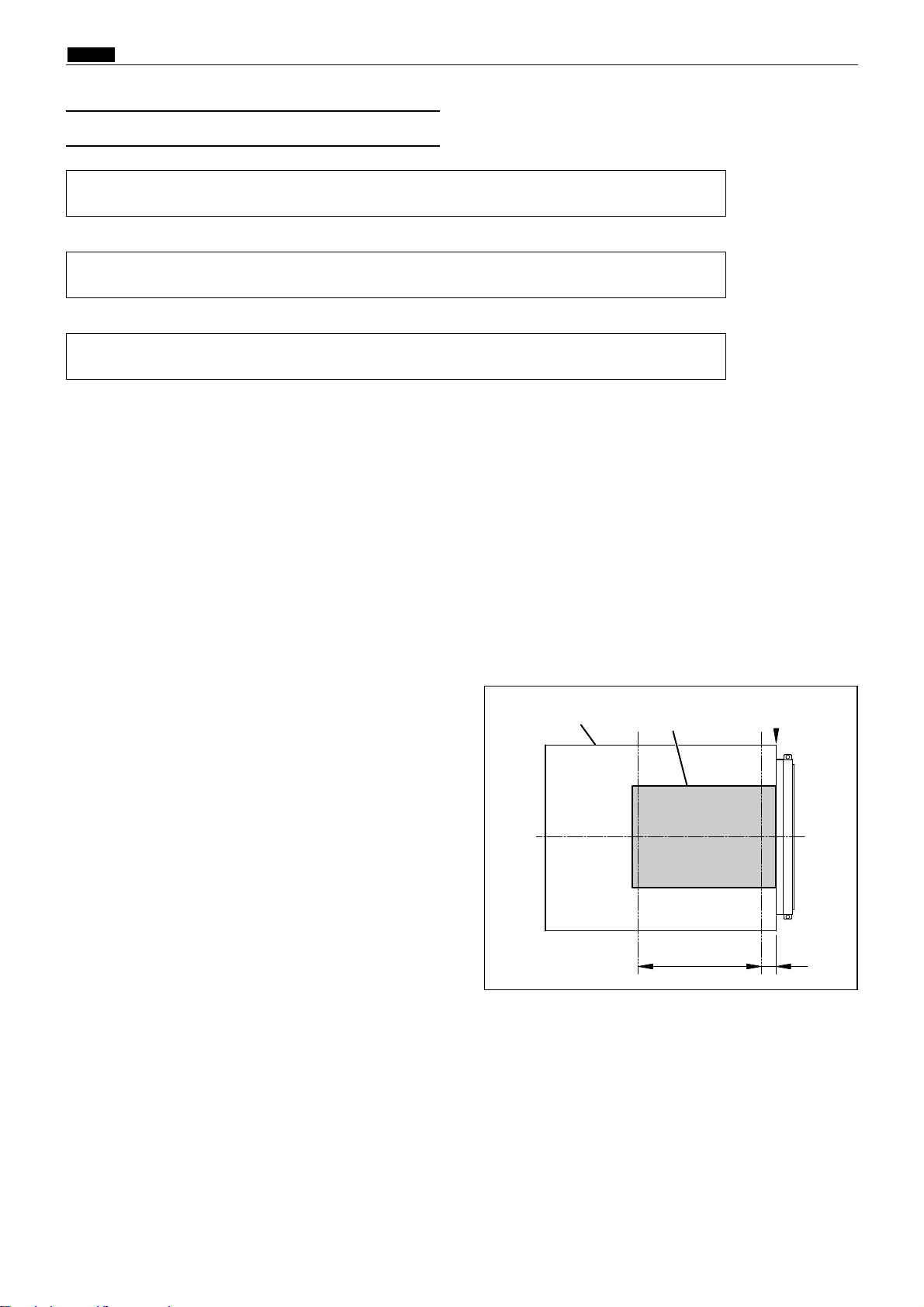
Platemaking Area for the Book Shadow Erasing Mode
When the platemaking is performed in the book shadow erasing mode, the platemaking area is limited 3
mm inner than the normal platemaking area as shown in the figure. 15mm is left in the central section
(stitching section).[Shadow erasing as desired is not included.]
* During multiple image printing, the book shadow erasing mode can not be used.
Platemaking Area for the Selected Paper
2The platemaking area varies depending on the selected paper size as shown below.
* When the magnification error is 0 in the pei path
direction or in the line progression direction, the
size for the same size (1:1) platemaking is shown.
A : Pel path direction
B : Line progression direction
NOTE
Selected paper size
A ( Remarks
A3
290A 414A
204 290
B4 251 358
A5 142 204
B5 176 251
LDG 273 414
LGL 210 350
LTR 210 273
STMT 172 210
MAX 290 414
11"914" 251 358
MINI 134 210
DP-440/430
DP-440/430
DP-440/430
DP-340/330
DP-340/330
A4 290 204
A4 R
1%)
B (
1%)
Page 33

36
z Scanner Section
chap.2
3. Function of Parts and Circuit
(1) Home Position Sensors
Description
PS1 detects the optical system home position when ADF is not used.
PS2 detects the optical system home position when ADF is used.
Scanner home position sensor (PS1)
Main PCB unit
Red
Blue
CN11-11
2
3
1
2
3
-3
Yellow
Red
Blue
Yellow
-2
5V
5V
5V
0
Photopassing :0V
Photointerrupting:5V
Circuit
Operation
23S0214
440W01e
Photointerrupting plate
Slider A
Scanner
home position sensor(PS1)
ADF
home position sensor(PS2)
Slider A
Photointerrupting plate
Photointerrupting
plate
Photointerrupting
plate
A shading plate is attached on slider A of the optical system. The position where PS1 is shaded becomes the
optical system home position when ADF is not attached.
The position where PS2 is shaded becomes the optical system home position when ADF is attached.
ADF home position sensor (PS2)
Red
Blue
CN11-41
2
3
4
5
6
-6
Orange
Red
Blue
Orange
-5
5V
5V
5V
0
Main PCB unit
Photopassing :0V
Photointerrupting:5V
440W02e
• Standard (ADF not attached) • With ADF attached
Page 34

37
z Scanner Section
chap.2
(2) Document Sensors
Description
Document sensors 1, 2 and 3 (pel path) sense the document's length in the pel path direction when it is
placed on the document glass.
Document sensor 4 (line progression path) / document sensor 5 (line progression path) senses the
document's length in the line progression path direction when it is placed on the document glass.
A3
B4
LG
LD
A4
LT
B5
ST
A5
A5R
B5R
LTR
A4R
STR
STR
LTR
MINIR MINIR
LD
LT LG
ST
MINI
A4R
A3
B5R
B4
A5R
A4
B5
A5
MINI
A3
B4
LG
LD
A4
LT
B5
ST
A5
A5R
B5R
LTR
A4R
STR
STR
LTR
MINIR MINIR
LD
LT
LG
ST
MINI
A4R
A3
B5R
B4
A5R
A4
B5
A5
MINI
440345e
Document
sensor 1,2,3
Document sensor 4
( A / B size )
Document
sensor 5
Document sensor 4
( inch size )
Page 35

38
z Scanner Section
chap.2
Document sensor 1,2,3 (pel path)
Document sensor 4 (line progression path)
Document sensor 5 (line progression path)
Light blue
Pink
CN12-11
2
3
1
2
3
-3
Light green
-2
5V
5V
Red
44
-4
Blue
55
-5
Green
Blue
CN12-61
2
3
6
7
8
-8
Red
-7
Gray
Blue
CN12-91
2
3
9
10
11
-11
Red
-10
5V
5V
5V
0
5V
5V
5V
0
Light blue
Pink
Light green
Red
Blue
Green
Blue
Red
Gray
Blue
Red
5V
0
Main PCB unit
Paper present :0V
No paper :5V
Paper present :0V
No paper :5V
Paper present :0V
No paper :5V
Circuit
440W03e
Page 36

39
z Scanner Section
chap.2
Description
The document cover position sensor detects opening and closing of the document cover (or ADF if the ADF is installed).
Operation
Sensor is photointerrupted with the document cover closed, The photointerrupter rotates as the document
cover is opened and sensor is photopassed.
Document cover position sensor
Red
Blue
CN6-11
2
3
22
23
24
-3
Light green
Red
Blue
Light green
-2
5V
5V
5V
0
Main PCB unit
Photopassing :0V
Photointerrupting:5V
Circuit
(3) Document Cover Position Sensor
2When the document cover is closed
Document cover position sensor : photointerrupted
2When the document cover is opened
Document cover position sensor : photopassed
440W04e
440338
Photointerrupted Photopassed
Fulcrum Fulcrum
OPEN
CLOSE
Page 37

40
z Scanner Section
chap.2
(4) CCD / Lamp
Description
The lamp illuminates the document and the reflected light is transmitted onto the CCDs.The CCDs output
the image signals in level of voltage.
This machine adopts a xenon lamp which is lit quickly when turned on, and the quantity of light is
stable.The lamp is lit when the the control signal CN1-1 for the lamp inverter unit is LOW (0V) .
The table below shows the specification for the CCD.
Drive PCB unit
Lamp inverter unit
CN9-9
7
8
9
-11
-10
CN1-1
-3
-2
CN12-1
-12
CN12-12
CN12-11
-1
CN2-1
-4
1
2
3
12
1
7
8
9
Gray
Brown
Blue
CCD PCB unit
Lamp
Document
Main PCB unit
Circuit
• Lamp
• CCD
Specification
No. Item Specification
1
Optical signal storage time (SH cycle) 2.048 msec./ line
2 Frequency 2.5MHz
3 The number of effective picture elements 4800 picture elements
4
Reading width
(This is not the image width which can be processed.)
305mm
5 Reading density
15.7 dot/mm(400DPI)
440W05e
Page 38

41
z Scanner Section
chap.2
Operation
When the
scanner unit
is closed, the switch is pressed; OPEN. the switch is attached to the plate spring,
which keeps the switch from too much pressure. When the
scanner unit
is open, the actuator is released; the
micro switch is turned to CLOSE.
Description
Opening and closing of scanner unit cover is detected by scanner unit cover open / close detection SW (MS3).
This machine does not work (except for the master cut SW and the jog SW) unless the scanner unit is closed
firmly. The machine stops immediately when the scanner unit is open. (after finishing platemaking if
platemaking is being performed.)
• When the scanner unit is opened •When the scanner unit is closed
Scanner open/close SW
When the scanner unit is closed:Open
When the scanner unit is opend:Close
Main PCB unit
Pink
Pink
CN4-14
-15
5V
5V
0
When the scanner unit is closed:0V
When the scanner unit is opend :5V
Circuit
(5) Scanner Unit Open / Close Detection
440W06e
440339
Scanner unitScanner unit
Switch ON
Switch OFF
Page 39

42
x Platemaking / Master Feed / Ejection Section
chap.2
xPlatemaking / Master Feed / Ejection Section
Make the master clump of the drum unit clump the master top end, performing platemaking on the master
with the thermal head. (In this machine, the master on the drum is ejected at the same time when
platemaking is performed.)
The master is conveyed to the drum unit via the platen roller and sponge roller1,2 by driving of the master
feed stepping motor, while it is being processed in the head section. Sponge roller2 is driven through the
master feed clutch (electromagnetic clutch), and controls the amount of master conveyed to the master clamp
section of the drum unit with the master feed clutch ON / OFF.
The end mark sensor starts to detect when the end mark (black) section printed on the end of the roll master
is conveyed. "CHANGE MASTER" is displayed on the LCD panel. The end mark sensor also detects whether
the master is conveyed properly through the sensor.
Cutter unit
Master feed clutch
Sponge roller 2
Master detection sensor
Master cover switch
Platen roller
Master cat
switch
Thermal head
Master feed stepping motorEnd mark sensor
1. Description
Platemaking / Master Feed Section
Platemaking / Master Feed section
Master Clump Opening /
Closing Section
Master Ejection Section
See page 54
See page 56
440315
440314
Thermal head up/down motor
Thermal head position sensor
Sponge roller 1
Master lead edge sensor
Page 40

43
x Platemaking / Master Feed / Ejection Section
chap.2
2. Sequence of Operation
(1) Operation when the master set
Platen roller
Master lead edge sensor
Photo passing
//
Photo interrupting
Sponge roller 1Switch ON
440346
440347
When the master cover is closed, the platen roller
and sponge roller1 rotate and feed out
the document for 10 seconds.
When the master lead edge sensor is interrupted,
the master is fed a few steps and stopped.
If the master lead edge does not reach the master
lead edge sensor, "MASTER SETTING ERROR" is
displayed.
Page 41

44
x Platemaking / Master Feed / Ejection Section
chap.2
Operation
When platemaking operation starts, the drum unit
rotates to perform master removal process. The
drum which has finished master removal process
stops at the master set position.
Open the master clump.
Sponge roller2 rotates with the master feeding
clutch ON. A certain amount of the master tip end
is fed to the master clump section and the sponge
roller stops.
Open the master clump
After the master clump is closed and clump the
master tip end, the drum rotates to roll up the
master.
When the master bottom end reaches the top of the
drum, master set is completed. Commence printing.
Master feeding clutch
Sponge roller 2
Master tip end
Master clump
Drum
Cutter
*Check the length of the master and
drum rotation angle to control the
drum rotation.
*As the electromagnetic clutch is OFF,
the sponge roller is free.
(2) Platemaking / Master Feeding
63S00211
63S00212
63S00213
63S00214
Page 42

292.6 0.1mm
45
x Platemaking / Master Feed / Ejection Section
chap.2
(1)Thermal Head
Description
The thermal elements are in alignment in the pel path direction, and are heated on the image section to make
holes on the master film.
Specifications
Circuit
3. Functions of Parts
DC-DC PCB unit
CN2-1
-14
Main PCB unit
CN5-1
-24
CN4-1
-6
-
CN1-1
-6
-
Thermal head
No. Item DP-440
1
Picture element density
400DPI (15.7 dot/mm)
2 Effective memory width
440W07e
DP-340
400DPI (15.7 dot/mm)
260.1 0.1mm
DP-430
300DPI (11.81 dot/mm)
DP-330
300DPI (11.81 dot/mm)
260.2 0.2mm
Page 43

46
x Platemaking / Master Feed / Ejection Section
chap.2
Exterior and Lot No.
Lot No.
Lot No. is shown with 4 digits including alphabet. Each digit has the following meanings. Serial No. in
the production month Production month (See the table) Production year
Serial No.
Serial No. in the production month
Production month (See the table)
Production year (Year of decade)
ABCDEFGHI JKL
Jan. Feb. Mar. Apr. May. Jun. Jul. Aug. Sep. Oct. Nov. Dec.
Sign
Month
NOTE :
Lot No.
Thermal resistor line
309 0.5(DP-440), 309 0.2(DP-430)
292.57 0.1(DP-440), 292.7 0.1(DP-430)
Signal connector
Pin (No.1)Pin (No.1)
Power connector
440349
440350
Thermistor
Label :DP-440 / DP-340 Label :DP-430 / DP-330
Lot No.
Label :DP-440 / DP-340
Label :DP-430 / DP-330
Page 44

47
x Platemaking / Master Feed / Ejection Section
chap.2
NOTE :
440351
H-43
0100
0101
0101
0101
0101
0110
0110
0110
H-44
1011
1000
1001
1010
1011
1000
1001
1010
Lank
1
2
3
4
5
6
7
8
1822 - 1860
1861 - 1899
1900 - 1939
1940 - 1979
1980 - 2019
2020 - 2059
2060 - 2099
2100 - 2139
0110 1011 9 2140 - 2179
0111 1000 10 2180 - 2220
0111 1001 11 2221 - 2261
0111 1010 12 2262 - 2302
0111 1011 13 2303 - 2343
1000 1000 14 2344 - 2384
1000 1001 15 2385 - 2425
1000 1010 16 2426 - 2466
Lank
00
01
02
03
04
05
06
07
3825 - 3908
3909 - 3993
3994 - 4077
4078 - 4162
4163 - 4246
4247 - 4330
4331 - 4415
4416 - 4499
08 4500 - 4583
09 4584 - 4668
10 4669 - 4752
11 4753 - 4837
12 4838 - 4921
13 4922 - 5005
14 5006 - 5090
15 5091 - 5075
DP-440 / DP-340 DP-430 / DP-330
Resistance value
Resistance
Resistance value is described on the label. When the head is replaced and the HELP mode is
initialized, set the DIP-SW (H-43,H-44) of the HELP mode.
HELP mode H-43,44 \ see p.263
Lank
Label :DP-440 / DP-340
Label :DP-430 / DP-330
Resistance valueLank
Page 45

48
x Platemaking / Master Feed / Ejection Section
chap.2
End mark sensor PCB unit
CN4-4CN1-1
-3
-4
-7
-6
5V
5V
5V
VR1
0
5V
Blue
Red
Light green
Blue
Red
Light green
-2
-5
OrangeOrange
4
Main PCB unit
Reflection light amount
The larger the reflection light amount is, the
smaller the output voltage is. The smaller the light
amount is, the larger the output voltage is.
The value is checked with the HELP 07.
* Adjustment of end mark PCB unit
Adjust the HELP mode H-07 so the difference
between the maximum value of the black level and
the white level becomes 20 or more.
HELP mode H-07 \ see p.228
Description
The end marks are located at a fixed distance
relative to the master; as the master is being fed,
the end mark sensor senses master condition and
the end marks by means of intensity of reflected
light.
(2) End Mark Sensor
End mark
End mark sensor
Circuit
23S0219
440W08e
2Value of the HELP mode H-07
Black level maximum
White level 5 Black level maximum - 20 or more
Page 46

49
x Platemaking / Master Feed / Ejection Section
chap.2
1. Master Setting Error Detection
Operation
In platemaking, the end mark sensor uses amount of reflected light to detect presence or absence of a master
on the transfer path. Then the following displays and operations are performed:
2When a master setting error is detected, "MASTER SETTING ERROR" is displayed and printing is not
processed.
2"MASTER SETTING ERROR" is only cleared by opening and closing the master cover.
(It is not cleared by turning the power off.)
2Printing is not performed but platemaking is only performed when the display is cleared after "MASTER
SETTING ERROR" is displayed. (Because the master is not attached to the drum.)
Timing
(1) While platemaking is being processed, the reflection light amount does not turn to be in a white level.
(Master detection sensor)
(2)
When platemaking process is finished (before printing process), the reflection light amount is in a white level.
MIN
MAX
HELP 07
Display value
Smaller
Larger
Reflection
light amount
White level top limit
Black level maximun 20 or more
Black level top limit
00
63
Timing
When it is considered that the end mark is read under the following conditions, "CHANGE MASTER" is
displayed.
q While the master is rolling up to the drum during platemaking, the following is checked.
w When the master passes under the end mark sensor, the amount of reflected light is read.
e If the following conditions are met, it is considered as master end.
Maximum Minimum 20 and Maximum white level top limit
2. Master End Detection
Operation
The end mark is printed on the area about 1 m from the end of the master.
2When the end mark is detected, "CHANGE MASTER" is displayed.
2When "CHANGE MASTER" is displayed, plate-making is not performed next.
(The display is not cleared by turning the power off.)
Page 47

50
x Platemaking / Master Feed / Ejection Section
chap.2
Master lead edge sensor
Main PCB unit
Red
Blue
CN4-281
2
3
7
8
9
-30
Green
Red
Blue
Green
-29
5V
5V
5V
0
Photopassing :0V
Photointerrupting:5V
(3) Master Lead Edge Sensor
Reflection light amount
The larger the reflection light amount is, the
smaller the output voltage is. The smaller the light
amount is, the larger the output voltage is.
The value is checked with the HELP 05.
Description
The master lead edge sensor is located at a fixed
distance relative to the master. By means of
reflected light, this sensor senses the presence of
the master on the master travel path. If the
intensity of the reflected light does not reach the
"white" level (which indicates presence of the
master) a single time during platemaking, "SET
MASTER ROLL PROPERLY" is displayed.
Circuit
HELP mode H-05 \ see p.224
440316
440W09e
Master lead edge sensor
Master
Page 48

51
x Platemaking / Master Feed / Ejection Section
chap.2
440317
(4) Master Detection Sensor
Reflection light amount
The larger the reflection light amount is, the
smaller the output voltage is. The smaller the light
amount is, the larger the output voltage is.
The value is checked with the HELP 07.
Description
The master detection sensor is located at a fixed
distance relative to the drum. By means of reflected
light, this sensor senses master setting errors.
When a master setting error occurs, "MASTER
SETTING ERROR" is displayed.
While the master is not set to the drum, printing
will not start even if the PRINT key is pressed.
Instead, “CANNOT PRINT” is displayed.
Master detection sensor PCB
CN10-1CN1-1
-2
-3
-3
-2
5V
5V
5V
VR1
0
5V
Red
Blue
Black
Main PCB unit
Circuit
HELP mode H-07 \ see p.229
Sensitivity adjustment of master detection sensor
Adjust variable resistor dial VR1 so that the
difference between the black and white levels is 30
or more. Preferably, the value when master
presence is sensed should be around 10.
Master detection sensor
440W10e
Page 49

52
x Platemaking / Master Feed / Ejection Section
chap.2
Description
Completed, the stepping motor for platemaking and the drum stops temporarily, the cutter motor is turned on
to drive the cutter and the master is cut.
CN1-1
-32
CN9-7
-8
Cutter motor(M5)
Black
Red
Black
Red
1
2
5
6
Drive PCB unit
-
CN3-1
-32
Main PCB unitDC-DC PCB unit
-
CN3-1
-12
-
CN3-1
-12
-
Circuit
(5) Cutter Unit
440W11e
Page 50

x Platemaking / Master Feed / Ejection Section
chap.2
53
Operation
1) In the platemaking process, when the drum stops
in the master winding position, the master
feeding clutch comes on, so that sponge roller2 is
driven and feeds out the master by a fixed
amount.
2) The master clump opens and closes, to clump the
master.
3) When the master is wound onto the drum, the
master feed clutch turns off, leaving sponge
roller2 free to be turned by the master as it is
wound off the drum.
(6)
Master Feed Clutch(Electromagnetic clutch)
Description
Sponge roller2 is attached to the bottom section of the master conveyance way of the master feeding unit, and
is driven via the master feeding clutch (CL1) by the platemaking motor. The rotation of sponge roller2 is
controlled with the master feeding clutch ON / OFF.
CN1-1
-32
CN9-5
-6
Master feed clutch
Black
Black
Black
Black
1
2
3
4
Drive PCB unit
-
CN3-1
-32
Main PCB unit
-
C
Circuit
63S00217
63S00218
63S00219
Master feeding clutch
Sponge roller 2
Master tip end
Master clump
Drum
B mode
C mode
B mode
23S0323E
Page 51

54
x Platemaking / Master Feed / Ejection Section
chap.2
When the drum stops at the plate detachment position and the master clump which clumps the master tip
end is opened (C mode), the pulling roller on the rolling section of the master ejection box pulls the master tip
end into the box inside, and the master is rolled up to the core.
If no core is installed, or when the master is fully wound onto the core, the core full switch (MS8) is
mechanically actuated, and the message "CHANGE MASTER EJECTION CORE" appears on the LCD panel.
Blue
Blue
Brown
Black
7
8
1
2
Roll-up motor
Ejection box sensor
Master ejection sensor
photo-emitting PCB
Master ejection box full switch
Master ejection sensor
photo-receiving PCB
Gray
Pink
Blue
Yellow
Orange
Orange
3
4
1
2
5
6
M
CN9-24
-25
-20
-21
-1
-2
-22
-23
Drive PCB unit
Main PCB unit
5V
5V
5V
1
2
1
2
16
17
Red
Blue
CN20-41
2
3
-6
Pink
-5
5V
5V
5V
0
Photopassing :0V
Photointerrupting:5V
2. Circuit
1. Description
Master Ejection Section
Pulling roller
Plate detachment
position
Master ejection sensor
photo-emitting PCB
Ejection box sensor
Master ejection box
full switch
Roll up motor
Master ejection sensor
photo-receiving PCB
440318
440W13e
Master ejection unit
Page 52

Timing
If the variation in the amount of light received by
the master ejection sensor during the making of 1
plate is less than a certain level (8 in the HELP06
display value), a plate ejection error is deemed to
have occurred.
55
x Platemaking / Master Feed / Ejection Section
chap.2
2. Rotation Control of the Roll-up Motor
If the roll-up motor is kept rotating when the master tip end is pulled to the ejection box in the plate
detachment process, the drum is actuated by the master and the stop position slips. To prevent this, the
roll-up motor is stopped when the master is detected by the master ejection sensor. (If the master is not
detected by the master ejection sensor, the Roll-up motor is stopped by the timer.)
(1) Master Ejection Sensor
Description
Photo-emission from the master ejection sensor is
received on the master ejection sensor, and the
sensor detects with the photo strength whether the
master is pulled to the master ejection box.
Photo-receiving amount is checked with the
HELP06.
1. Master Ejection Error Detection
Operation
While one platemaking is being processed, the difference of photo-receiving amount is less than 8 by checking
with the HELP5, which is determined as an master ejection error. The following display and operation are
shown.
2"PLATE EJECTION ERROR" is displayed on the LCD panel and printing is not processed.
2"PLATE EJECTION ERROR" is cleared with the ALL CLEAR key , STOP key pressed.
2A master ejection error is not detected for one platemaking soon after a plate ejection error or master
setting error is detected.
¡If incorrect sensing occurs due to sensor malfunction, etc., HELP32can be used to
prohibit plate ejection error sensing.
IMPORTANT :
Smaller Larger
Photo-receiving amount
3. Function of Parts
HELP mode H-32 \ see p.254
HELP mode H-06 \ see p.226
HELP mode H-06 \ see p.226
2
HELP mode H-06 value
00
63
2
HELP mode H-06 value
Value without master : the photo receiving amount of
the master ejection sensor at the position where the
first paper jam is detected after starting platemaking.
00
Threshold value
63
Threshold value :
Value without master + 8
Time
Page 53

56
x Platemaking / Master Feed / Ejection Section
chap.2
1) When platemaking starts, the drum unit rotates
from the stop position to the opening / closing
lever section (master removal position) and it
stops temporarily. (B mode)
1. Description
The master clump on the drum unit is opened or closed by the two opening / closing levers' rotation operation.
The opening / closing levers (one for the master set position, and the other for the master removal position)
are on the master clump opening / closing section on the main body rear side.
The master clump is opened or closed during platemaking. Opening / closing operation is as follows:-
5) Rotate the drum, to wind the master onto it.
4) Open and close the master clump to have it grip
the leading edge of the used master.
3) Close the master clump, rotate the drum again
and stop the drum at the next opening / closing
lever section (master set position).
2) Open the master clump to have the used master
tip end gripped by the plate ejection unit.
Master Clump Opening / Closing Section
Master clump opening / closing lever
(Master set position)
Master clump opening /
closing section
440319
Master clump opening / closing lever
(Master removal position)
Page 54

57
x Platemaking / Master Feed / Ejection Section
chap.2
The following is the structure of the master clump opening / closing section viewed with the rear cover opened.
The rotation stop position of the master clump opening / closing lever is determined by the clump motor and
two cams. There are 3 rotation stop positions: A mode, B mode and C mode. Their functions are as follows:-
(1) Structure
2. Operation of Master Clump Open / Close Lever
The drawing below is a section through the machine's interior, viewed from the control side.
Master clump opening / closing lever
Master clump opening / closing section
2A mode 2B mode 2C mode
Clump motor
B mode adjusting cam
Master set position
Drum
Master removal position
A / C mode adjusting cam
B mode sensor
A / C mode sensor
Master clump opening / closing lever
Master clump
23S0266
Page 55

58
x Platemaking / Master Feed / Ejection Section
chap.2
(2)
Master Set / Removal Operation
The drum rotates to the master
removal position Stop
The drum rotates to the master
set position Stop
Page 56

59
x Platemaking / Master Feed / Ejection Section
chap.2
(3) Clump Opening / Closing Lever
Position (A / B / C Mode)
Mode Photointerrupter stop position / state of sensor
Functions
In the normal state or during printing, the
master clump opening / closing lever turns
out from the master clump opening /
closing lever.
A
m
o
d
e
B
m
o
d
e
C
m
o
d
e
The master clump opening / closing lever
pinch the master clump opening / closing
arm.
The master clump is open. This state
occurs when the master is set or removal.
B mode sensor
(PS4)
B mode sensor
(PS4)
B mode sensor
(PS4)
A / C mode sensor (PS3)
A / C mode sensor (PS3)
A / C mode sensor
(PS3)
Photointerrupting
gPh
oto-passing
or
Photopassing
g
Photo-
interrupting
Photopassing
Photointerrupting
Photo-interrupting
Photopassing
Photopassing
Page 57

60
x Platemaking / Master Feed / Ejection Section
chap.2
The mode is detected under the following conditions
2A mode
When the B mode sensor (PS4) is photointerrupted, the A / C mode sensor (PS3) detects the edge of
photointerrupting fphotopasing.
*With the power ON, the A mode is determined when the B mode sensor is in the photointerrupting state
and the A/C mode sensor is in the photopassing state. If not in the A mode with the power ON, the
master clump opening / closing lever rotates to the B mode and stops. When the lever stops at the
B mode, the drum rotates with the drum rotation switch and returns to the A mode at the stop position.
2B mode
When the A/C mode sensor is photointerrupted, the B mode sensor detects the edge of photointerrupting /
/photopassing or photopassing - photointerrupting.
2C mode
When the B mode sensor is photopassing, the A/C mode sensor detects the edge of photointerrupting
f
photopassing.
(1) A / B / C Mode Sensor
B mode detection sensor(PS4)
Main PCB unit
Red
Blue
-91
2
3
-11
Green
-10
5V
5V
5V
0
A/C mode detection sensor(PS3)
Red
Blue
CN17-31
2
3
-5
Orange
-4
5V
5V
5V
0
CN1-1
-32
CN9-26
-27
Clump motor(M3)
Yellow
Orange
2
1
18
19
Drive PCB unit
-
CN3-1
-32
-
Photopassing :0V
Photointerrupting:5V
Photopassing :0V
Photointerrupting:5V
Circuit
Operation / Sequence
3. Function of Parts
440W14e
Page 58
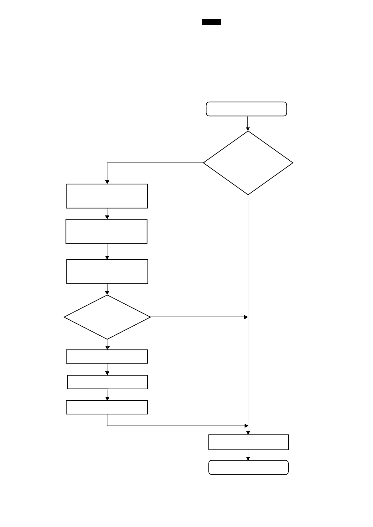
61
x Platemaking / Master Feed / Ejection Section
chap.2
4.
Returning Operation Flowchart When the Power Is Cut Off Accidentally
The machine returns to the initial state automatically when the power is turned off mistakenly during processing platemaking, master removal and master set simultaneously or when the power returns after it is
interrupted.
Power ON
Master removal / set process
"PLEASE WAIT" display
Set / removal operation
continues
"PLATE EJECTION ERROR"
displayed?
Open the scanner
Remove the mis-set master
Close the scanner
Standby
Initial desplay
Is the state the same
as the previous state
(before the power
is turned OFF)?
Process other than
removal / set
"PLEASE WAIT" lights out
no
Power ON
yes
Page 59

62
c Paper Feed Section
chap.2
1. Description
Feeding of the paper is performed by the paper separator (employing the center separation method) and paper
feed roller (there is no corner finger). Elevation of the feed tray is powered by the elevator motor.The paper
lead edge sensor is equipped at the rear of the paper feed roller. When the paper does not reach the paper lead
edge sensor or the signal sensor during the preliminary feeding, “PAPER JAM ON THE LEFT SIDE” appears.
Paper fed by the paper separator and paper feed roller is fed further by the timing roller and guide roller to
the point where its leading edge is sandwiched between the drum and the press roller. Then the pression of
the timing roller and guide roller is released (by moving the guide roller upward several mm), so that the
paper is fed through at a speed equal to the circumferential speed of the drum and press roller. The press
roller sensor senses the paper feed condition; if a feed error occurs, the message “PAPER JAM ON THE
FEEDER SIDE” is
displayed.
For details, see “1.Paper Jam Detection Timing” in chapter 2 (n Paper ejection section).
\See page 90
cPaper Feed Section
(Signal solenoid)
440301
Paper separator
Paper feed roller
Elevator motor
Feed traySupplemental paper tray
Timing roller
Press roller
Guide roller
P-roller sensor
LPU
(Long Paper Unit)
Paper detection sensor
Elevator top limit sensor
Elevator bottom
limit switch
Paper feed stepping motor
Printing position
adjusting unit
Paper lead edge sensor
Double feed detection sensor
Page 60

63
c Paper Feed Section
chap.2
Timing roller
Paper feed segment
Timing segment
Pinion gear
Paper feed roller
When the main motor turns, the paper feed cam rotates, causing the paper feed segment and timing segment
to execute the reciprocating motion shown below, which turns the pinion gear.
2. Operation
(1) Rotation of the Paper Feed Roller and
Timing Roller
440302
Paper feed cam
Page 61

64
c Paper Feed Section
chap.2
The paper feed roller is driven by the paper feed stepping motor via the timing belt. The rotational timing is
controlled by the program.
(2) Paper Feed Roller Drive
Paper feed roller
Paper feed stepping motor
Timing belt
440303
Page 62
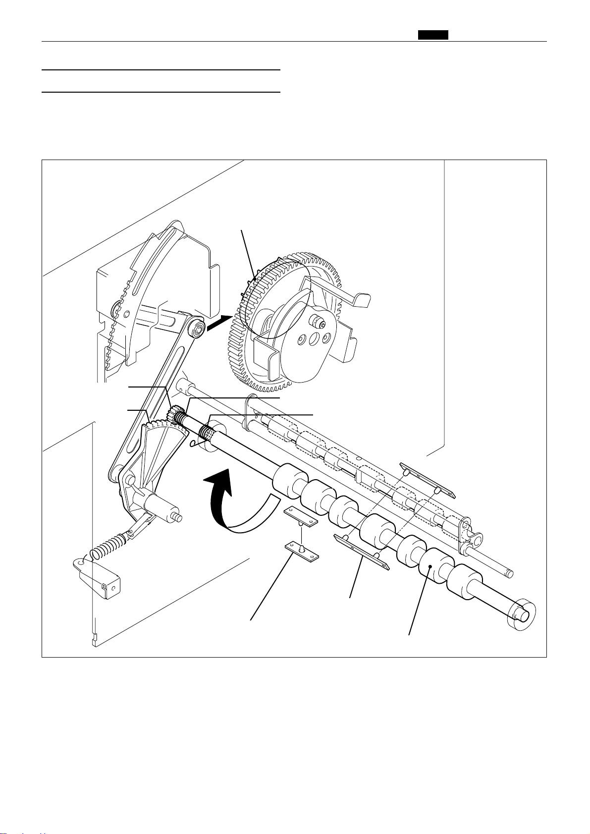
65
c Paper Feed Section
chap.2
Timing roller is actuated to rotate by the pinion gear and spring clutch. When the paper feed cam rotates, the
reciprocating motion of the timing roller segment is transmitted to the pinion gear, and the spring clutch
works to rotate the Timing roller in the direction of conveyance.
(3) Driving of the Timing Roller
Timing roller
Paper feed cam
Spring clutch
Spring clutch
Pinion gear
Paper feed segment
440304
Paper lead edge sensor
Double feed detection sensor
Page 63

66
c Paper Feed Section
chap.2
440305
After the Press roller is pressed to the drum, the printing paper is gripped firmly with the drum and Press
roller, the Guide roller is released from the Timing roller. This is called "escaped". Escape timing is within a
period when the printing paper is conveyed about 10 mm after it is gripped with the drum and Press roller.
(4) Escape the Guide Roller
¡When the timing is too late, the printing paper is gripped at two places too long. Thus
master elongation and slippage occur.
¡On the contrary, when the timing is too early, the printing paper is not gripped at all, and it
is not well settled. Thus creasing of paper and dispersion of the printing position occurs.
IMPORTANT :
Escape cam
Timing roller
Guide roller sensor
Press roller
Guide roller
Paper
Drum
about
10mm
about
10mm
Guide roller motor
Page 64

67
c Paper Feed Section
chap.2
The “paper feed length” is the length by which the paper feed roller feeds out the print paper. When the paper
feed roller feeds out the print paper, the guide roller is pressed against the timing roller and does not rotate;
as a result, the paper arches up between the paper separator and the timing roller, since the distance between
these two items is only 80mm, while the length by which the paper is fed out from the paper feed roller is
95mm. This arching has the effect of correcting any skewing of the paper (as the leading edge is held firm
between the guide and timing rollers). It also has the effect of lessening the load on the timing roller when it
feeds the paper through, thus minimizing slippage.
For feed amount, the leading edge of the paper is detected by the paper feed length sensor and paper feed is
controlled by program( HELP mode H-86,88 ).
HELP mode H-86,88 \ see p.294,296
¡If paper feed length is too large: the arching dimension will be too large, and if the paper is
of a very stiff type, it will buckle up between the paper feed roller and the paper feed inlet
(upper), causing a PAPER JAM error ("PAPER JAM ON THE FEEDER SIDE").
¡If paper feed length is too small: the arching dimension will be too small, so that arching
will be unable to correct skewing of the paper, and skewing and wrinkling will be liable to
occur. Furthermore, the slippage that occurs when the timing roller feeds the paper
through will be very large, resulting in printing position errors.
IMPORTANT :
(5) Paper Feed Length
Cam follower
Paper feed cam
Paper feed roller
Guide roller
Paper separator
Timing roller
440306
Paper lead edge sensor
Double feed detection sensor
Page 65

68
c Paper Feed Section
chap.2
The printing position is adjusted by changing the
timing of the paper toward the drum with the
PRINTING POSITION key on the control panel.
Description
When the PRINTING POSITION key on the control
panel is pressed, the link cam is driven by the
motor. As the link cam moves, the cam follower
position (bearing) from the paper feed cam changes.
Accordingly drive timing for the timing roller can
be changed.
2Press the key ;
Cam follower moves in the direction of : e Drive timing of the timing roller becomes earlier.
Paper timing becomes earlier, and the picture image moves backward.
2Press the key ;
Cam follower moves in the direction of : b Drive timing of the timing roller becomes later.
Paper timing becomes later, and the picture image moves forward.
(1)
Printing Position Adjusting Mechanism
¡
Pressing makes cam follow-
er move in the bdirection
¡
Pressing makes cam follow-
er move in the edirection
Timing roller
Link cam
Printing position motor
Paper feed cam
Cam follower
440307
3. Functions of parts
ADJUST
PRINT POS.
OK
Top / bottom
center sensor
Top / bottom
encoder sensor
440352e
Page 66

69
c Paper Feed Section
chap.2
Top/bottom center sensor
Main PCB unit
Red
Blue
-291
2
3
-31
White
-30
5V
5V
5V
0
CN1-1
-32
CN9-3
-4
Top/bottom motor(M6)
Orange
Yellow
1
2
1
2
Drive PCB unit
-
Photopassing :0V
Photointerrupting:5V
Top/bottom encoder sensor
Red
Blue
CN20-11
2
3
-3
Black
-2
5V
5V
5V
0
Photopassing :0V
Photointerrupting:5V
Circuit
Operation
Top and bottom limit of print position is detected by
the top/bottom encoder sensor and the center sensor.
The center position is detected by the standard
position sensor.
The top/bottom encoder sensor detects the
top/bottom motor rotation.
The main PCB unit controls the number of
top/bottom motor rotations with the top/bottom
encoder sensor signal.
Operation with the Power ON
The printing position returns to the standard
position by operating with the power ON,
depending on the sensor state as follows.
2
When positioned between the standard position
and the bottom limit:
Rotate the printing position motor normally (CW)
to return the printing position to the standard.
2
When positioned between the standard position
and the top limit:
Rotate the printing position motor reversely
(CCW) to return the printing position to the standard.
Top/bottom center sensor
Printing position
Top/bottom encorder sensor
Bottom limit Standard Top limit
: Photointerrupting
: Photopassing
440W15e
440353e
Page 67

70
c Paper Feed Section
chap.2
Description
Circuits
Double feed detection sensor
photo-receiving PCB
(2) Double Feed Detection Mechanism
The double feed detection sensor is mounted at the rear of the paper lead edge sensor to detect feeding of multiple papers.
When it is detected, “DOUBLE FEEDING ERROR” is displayed on the LCD. If double feeding occurs with the
tape cluster (optional) equipped, the tape is inserted.
440W32e
440354
Blue
CN4-1
-2
Main PCB unit
Drive PCB unit
Main PCB unit
Light green
5V
5V
5V
5V
4
3
-8
CN8-7
Glay
Blue
1
2
Paper lead edge sensor
photo-emitting PCB
Double feed detected sensor
photo-receiving PCB
-10
CN8-9
White
Blue
1
2
Signal sensor
photo-emitting PCB
-6
CN4-5
Blue
Pink
4
Blue
CN8-11
-12
Orange
5V
2
1
Signal sensor
photo-receiving PCB
Blue
CN4-2
-3
Yellow
5V
3
1
Paper lead edge sensor
photo-receiving PCB
5
Double feed detected sensor
photo-emitting PCB
Double feed detection sensor
photo-emitting PCB
Paper lead edge sensor
photo-receiving PCB
Paper lead edge sensor
photo-emitting PCB
Page 68

71
c Paper Feed Section
chap.2
(3)
Elevator Top Limit Sensor
Description
Circuits
Operation
The elevator top limit sensor senses decrease of the paper pile, and the top limit position of the feed tray.
It does so by detecting the up/down motion of the paper feed shaft.
Sensing of feed tray top limit
2When the feed tray rises, the paper in it presses the paper feed roller upward, making the paper feed shaft
lever (photointerrupter) rotate upwards about its fulcrum, until it no longer obstructs the sensor’s light
beam. Restoration of the sensor’s light beam signals that the paper tray has reached the top limit, and
triggers stopping of the feed tray’s rise.
Sensing of paper decrease
2As printing progresses and the paper decreases, the paper feed roller gradually descends, until it obstructs
the sensor’s light beam. When this happens, the feed tray is raised until the light beam is restored.
If the light beam is not restored within about 30 seconds of the sending of the RAISE FEED TRAY
command, error E002 (elevator lock) is displayed.
Elevator top limit sensor(PS9)
Red
Blue
CN4-221
2
3
3
4
5
-24
Light green
Red
Blue
Light green
-23
5V
5V
5V
0
Main PCB unit
Photopassing :0V
Photointerrupting:5V
440W16
440311
Paper feed roller
Elevator top limit sensor
Paper
Paper feed shaft lever Elevator top limit sensor
Paper
Page 69
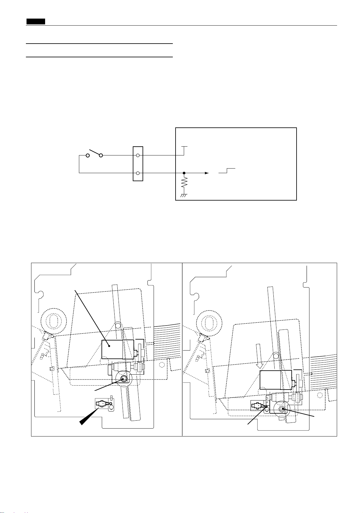
72
c Paper Feed Section
chap.2
(4)
Elevator bottom Limit Switch
Description
Circuits
Operation
This is a micro switch that senses the bottom limit position of the feed tray.
When the feed tray rises, the bracket disengages from the switch and the switch closes. When the feed tray
descends to its bottom limit position, the bracket engages the switch’s actuator, opening the switch.
If the switch does not open within about 30 seconds of the sending of the LOWER FEED TRAY command, error
E002 (elevator lock) is displayed.
Elevator bottom limit switch
descent(push):OPEN
Light blue
Light blue
CN4-20
-21
5V
5V
0
1
2
Main PCB unit
440W17e
Elevator motor
Actuator
440312
Elevator bottom
limit switch
2Bottom limit position
Gear
Gear
Page 70

73
c Paper Feed Section
chap.2
¡
When there is no paper :
¡
When there is paper placed :
(5) Paper Detection Sensor
Description
Circuits
Operation
Senses presence/absence of paper in the feed tray. When the paper in the tray runs out, the message "ADD
PAPER" is displayed and printing stops.
When there is no paper, the sensor is in the state of photopassing(open). When paper is placed inside, the
sensor is in the state of photointerrupting(close). When an absence of paper is detected, the message "ADD
PAPER" is displayed on the LCD panel.
2When absence of paper is sensed, platemaking, printing and test printing are not possible.
2If the paper runs out during printing, "ADD PAPER" is displayed on the LCD panel, printing is stopped,
and the feed tray descends to its lower limit position.
2If the paper runs out during platemaking, operation continues until the end of the platemaking process,
then operation stops (without proceeding to the printing process), and the feed tray descends to its lower
limit position.
Paper detection sensor
paper present : CLOSE
paper absent : OPEN
Red
Blue
CN4-251
2
3
6
7
8
-27
Purple
Red
Blue
Purple
-26
5V
5V
5V
0
Main PCB unit
Photopassing :0V
Photointerrupting:5V
440313
440W18e
Photointerrupting
Photopassing
Paper
Paper detection sensor
Page 71

74
c Paper Feed Section
chap.2
(6) Long Paper Unit Mechanism (Option)
Circuits
Brown
White
2
1
G - roller motor
M
CN9-1
-2
Drive PCB unit
G - roller
sensor
Red
Blue
CN9-28
1
2
3
-30
Yellow
-29
5V
5V
5V
0
Photopassing :0V
Photointerrupting:5V
440W33e
Description
With the LPU unit equipped, duration the timing roller and the guide roller are detached from each other is
extended (the guide roller is lifted by a few millimeters), thus the paper with the maximum length of 540 mm
can be fed through.
Page 72

75
v Drum Driving Section
chap.2
vDrum Driving Section
1. Description
Main motor encoder sensor
Encoder
Main motor
Drum gear
Drum stop / JAM detection
position sensor
Drum position cam
440320
Master set / removal
position sensor
Page 73

76
v Drum Driving Section
chap.2
440322
Drum position cam
(1) Drum Stop / JAM Detection Position
Sensor
2. Function of Parts
The drum stop / JAM detection position sensor detects the drum stop position and JAM detection position.
2The drum stop position is the position where the drum stops at the same time when a beep sounds after the
JOG switch (drum rotation switch) is kept pressing.
2The JAM detection position is the timing to check paper jamming in the paper ejection section.
2Paper jamming in the paper ejection section is checked in the above timing with the jam sensor (photo-
receiving) and P roll sensor.
Operation
The drum stop / JAM detection position sensor is positioned while the drum is rotating as follows:-
2The drum stop position is detected with the edge of photointerrupting / photopassing.
2The JAM detection position is detected with the edge of photopassing / photointerrupting.
Drum stop/JAM detection position sensor(P5)
Red
Blue
CN17-61
2
3
-8
Yellow
-7
5V
5V
5V
0
Main PCB unit
Photopassing :0V
Photointerrupting:5V
Circuit
440W19e
Drum stop/JAM detection
position sensor
JAM detection
position
JAM detection
position
Drum stop
position
Drum stop
position
Drum stop/JAM detection
position edge
Drum stop/JAM detection
position sensor
JAM detection position edge
Page 74

77
v Drum Driving Section
chap.2
(2) Master Set / Removal Position Sensor
The master set / removal position sensor detects the drum stop position when the plate is attached or
detached. It also detects the speed reducing timing for stopping at the printing speed and for pressing the
JOG switch (drum rotation
switch).
Operation
The following is the state of the master set / removal position sensor while the drum is rotating.
2The master detachment position is detected with the edge of photopassing fphotointerrupting.
2The master set position is detected with the edge of photointerruptingfpotopassing.
2The drum speed is reduced to the slow (before-stop) speed at the master removal position before the drum
stops.
Master set/removal position sensor(PS6)
Red
Blue
CN17-121
2
3
-14
Purple
-13
5V
5V
5V
0
Main PCB unit
Photopassing :0V
Photointerrupting:5V
Circuit
440W20e
Master set/removal position sensor
Master removal
position
Master set
position
Master removal
position
Master set
position
440321
Drum position cam
Master removal position edge
Master set position edge
Master set / removal
position sensor
Page 75

78
v Drum Driving Section
chap.2
Description
The drum rotates as long as the JOG switch (drum rotation switch) is pressed (within one rotation) and stops
at the stop position with a beep.
When the drum stops there, the LED mounted on the JOG switch 1 will light up.
In the normal state, the drum rotates (within one
rotation) when the JOG switch (drum rotation
switch) is kept pressed and the drum stops at the
stop position, reducing the speed to the slow
(before-stop) speed at the first master removal
position.
When the P-roller sensor is in the photopassing
state (P-roller ON) at the first plate detachment
position, the drum passes the stop position
without reducing the speed.
Drum rotation 1 switch
Drum rotation 2 switch
Purple
Purple
CN4-8
-9
5V
5V
0
Light green
Light green
CN21-5
-6
5V
5V
0
1
2
Main PCB unit
Circuit
(3)
JOG Switch 1,2 (Drum Rotation Switch 1,2)
JOG switch
(Drum rotation switch)
JOG switch (drum rotation switch) (SW3)
440355
440W21e
2When the JOG Switch (Drum Rotation Switch) Is
Pressed Down
Sequence of Operation
Drum stop/JAM detection position sensor
Master removal position
Master set
position
Drum stop position
JAM detection position
Master removal position :
drum reduce the speed
Drum stop position : drum stops
Master set/removal position sensor
Main motor
P-roller sensor
When the P-roller sensor is in the photopassing state(P-roller ON),
the drum dose not reduce the speed at the master removal position.
JOG switch
(Drum rotation switch)
Page 76

79
v Drum Driving Section
chap.2
(4) Control of the Main Motor
Main motor encoder sensor(PS7)
DC24V
Main motor(M1)
Main motor PCB unit
Main PCB unit
Red
Blue
Red
Brown
Brown
Blue
Blue
Blue
CN1-1
CN4-1
-2
-3
-4
CN5-1
-2
1
2
3
-3
Gray
-2
5V
5V
5V
0
Main 4
Main 3
Main 2
Main 1
Inter lock monitor
Encoder dividing
+5V
GND
CN3-1CN15-21
-22
-23
-24
-25
-26
-27
-28
-2
-3-4-5
-6-7-8
Blue
Red
Orange
White
Black
Gray
Light blue
Purple
Terminal plate(+24)
Terminal plate(GND)
Circuit
440W22e
Page 77

80
v Drum Driving Section
chap.2
1. Rotation Speed Control by Encoder Sensor
The encoder sensor detects the main motor
rotation. The main motor PCB Unit controls the
number of main motor rotations with the encoder
sensor signal. The encoder sensor signal is
transmitted to the main PCB Unit as encoder
dividing signal (8 dividings). The number of main
motor rotations is checked with the HELP01.
2. Selecting the Speed
The speed is selected with the main 1 - 4 on the main PCB Unit.
The following are the speed depending on the pin state.
Slow 2 is applied to accelerating only. it is not used to reduce the speed. All the speeds
including slow 1 are accelerating speeds. if the slow 1 is not operated, all the other speeds
are not operated.
IMPORTANT :
STOP
Pre-stop 1 Pre-stop 2
JOG
1st
SPEED
2nd
SPEED
3rd
SPEED
4th
SPEED
5th
SPEED
CN 15-25 Main 1
1
L H L H L H L H
-26 Main 2
1
L L H H L L H H
-27 Main 3
1
L L L L H H H H
-28 Main 4 H L L L L L L L L
HELP mode H-01 \ see p.217
Page 78

81
b Press Section
chap.2
bPress Section
1. Description
(1) Press Roller Timing & Printing Area
Description
In this machine, the master is rolled up to the
drum, ink is transferred to the drum and the
printing paper is pressed to the drum by the press
roller to print.
Printing is performed on only the sections that
meet the following requirements.
1) The sections of the master on which holes are
made by processing platemaking. (platemaking area)
2) The hole sections of the drum.
3) The section of the drum pressed with the
press roller. (the area pressed ON)
When the pressed-on position is 0 under the
normally adjusted conditions, relations among 1), 2)
and 3) are as follows*-
Drum gear
Press roller
Press lever
P-roller sensor
(mm)
DP-440/430
428
438
423
Press ON length
Drum hole section length
Printing area length
440308
Center of the
master clump shaft
Bottom end of the
hole section
Cam
Paper
Cancel lever
Signal solenoid
Contact pressure unit
70
42315
6
54
( mm )
Cancel lever
DP-340/330
370
370
355
: 438
: 370
DP-340/330
DP-440/430
: 423
: 355 Printing area
DP-340/330
DP-440/430
: 428
: 370 Press area
DP-340/330
DP-440/430
: 310
: 270
DP-340/330
DP-440/430
Page 79

82
b Press Section
chap.2
The press roller is ON (the press roller is pressed to the drum) or OFF by operating the press lever up and
down with the cam inside the drum gear.
Press roller : OFF Press roller : ON
Do not press off later than the hole
section end position since ink
seeps from the bottom end of the
master.
IMPORTANT :
Adjusting the printing area means that the cam
curve goes up and down as shown in the figure. The
timing of drum ON / OFF varies depending on the
cam curve`s up and down. The ON position is before
the drum hole section, so the printing area is not
influenced. (Do not shorten the printing area length
as it is influenced.) The OFF position is only
changed and the printing area is adjusted.
P-roller sensor
Cam
Press roller
Press lever
440309
Press OFF position Press ON position
Drum hole section
end
Drum hole section
start
Printing
area
Printing area
Cancel lever
Signal solenoid
: 423mm
: 355mm
DP-340/330
DP-440/430
Page 80

83
b Press Section
chap.2
(1) P- roller Sensor
The P- roller sensor detects up and down of the press roller.
The press roller only ascends when the paper is fed from the paper feed section by the cancel lever.
The P- roller sensor also is used to know whether the paper is fed.
Operation
The P- roller sensor position varies depending on the press roller position as follows:-
• When the press roller is OFF (DOWN) : photointerrupting
• When the press roller is ON (UP) : photopassing
P-roller sensor(PS8)
Main PCB unit
Red
Blue
CN17-151
2
3
-17
Light blue
-16
5V
5V
5V
0
Photopassing :0V
Photointerrupting:5V
Circuit
2. Function of Parts
440W23e
Press roller : OFF Press roller : ON
Cam
Press roller
Press lever
440309
P-roller sensor
Cancel lever
Signal solenoid
Page 81

84
b Press Section
chap.2
(2) Switching the Contact Pressure
The contact pressure can be switched on the operation panel. When it is changed on the operation panel, the
contact motor will start up to effect the switch as soon as the PRINT key is pressed.
Circuits
Brown
Purple
1
2
1
2
Pressure motor
Pressure center switch
Green
Green
1
2
M
CN12-8
-9
CN21-1
-2
Drive PCB unit
Main PCB unit
5V
Pressure position switch
White
White
3
4
-3
-4
5V
Pressure encoder sensor
Red
Blue
CN12-10
1
2
3
-12
Orange
-11
5V
5V
5V
0
1
3
2
Photopassing :0V
Photointerrupting:5V
Press roller
Pressure center
switch
Pressure motor
Pressure
encoder sensor
Pressure
position switch
440310
440W24e
Page 82

85
b Press Section
chap.2
2Low contact pressure position:
Sensed by pressure center switch.
Switch turns from OFF to ON in response to
movement in the direction of the arrow.
2Standard contact pressure position:
Sensed by pressure center switch.
Switch turns from OFF to ON in response to
movement in the direction of arrow 1.
Switch turns from ON to OFF in response to
movement in the direction of arrow 2.
2Hi contact pressure position:
Sensed by pressure position switch.
Switch turns from ON to OFF in response to
movement in the direction of arrow1.
Switch turns from OFF to ON in response to
movement in the direction of arrow2.
1. Contact pressure position sensing
1 2
1
2
440362
440363
440364
Pressure position switch
Pressure center switch
Pressure center switch
Drum unit
Press roller
Page 83
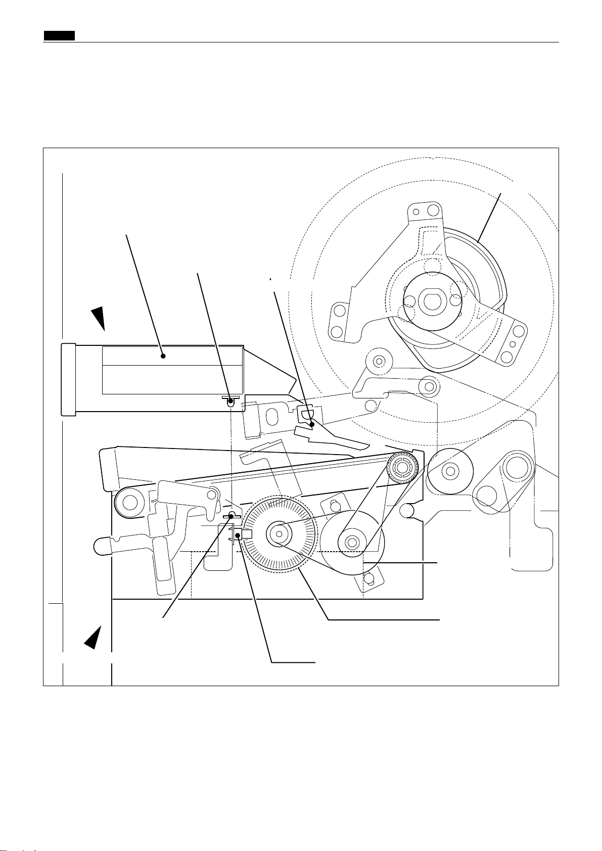
86
n Paper Ejection Section
chap.2
nPaper Ejection Section
1. Description
In the paper ejection section the printed paper is removed from the drum and is ejected to the print tray.
Escape cam
Paper stripper finger
Paper ejection motor
Top blow fan
440323
Paper ejection fan
Eject fan encoder sensor
Paper ejection JAM
sensor(Photo-emitting)
Paper ejection JAM
sensor(Photo-receiving)
Paper ejection fan unit
Top blow fan unit
Page 84

87
n Paper Ejection Section
chap.2
2. Functions of Parts
Mechanical Structure and Operation
In addition to the paper stripper finger installed in the center, there are two sub paper remover fingers on
both sides. There is an air diffuser on the tip of the finger. Compressed air transmitted from the air pump is
blowed out of this hole to detach the tip end of the paper from the drum.
To remove the paper from the drum firmly, the gap between the tip of finger and the drum surface and
between the tip of finger and the corner of the master clump are adjusted as follows:-
Air pump
Sub paper
stripper finger
Paper
stripper finger
Sub paper
stripper finger
Drum
surface
Approx
0.5mm
Paper stripper
finger
(1) Paper Stripper Finger
440325
440324
Page 85

88
n Paper Ejection Section
chap.2
-3
-4
Top brow fan 2
Red
Black
1
2
CN10-1
-2
Top brow fan 1
Red
Black
1
2
22
23
20
21
Drive PCB unit
F
F
Operation
During printing, the fan blows a constant stream of air at the paper stripper finger, from the rear. This assists
paper stripping and also presses the paper against the ejection belt, which stabilizes ejection.
Top blow fan
Paper stripper finger
Circuit
(2) Top Blow Fan
440W26e
440328
Top blow fan unit
Top blow fan 2
Top blow fan 1
Page 86

89
n Paper Ejection Section
chap.2
Description
The JAM sensor photo-receiving element is installed on the paper ejection fan unit and detects whether the
paper is ejected normally. When it is detected that the paper is not ejected normally, "PAPER JAM ON THE
EJECTION SIDE" is displayed on the LCD panel.
Operation
The JAM photo-emitting PCB is installed in the top blow fan, and the photo-receiving PCB in the paper
ejection fan unit. HIGH with the optical path interrupted. LOW with the optical path passing.
There are two cases of interruption; interrupted by the paper and the top blow fan is open.
Circuit
(3) Paper Ejection JAM Sensor
440W25e
440326
Paper ejection JAM
sensor(Photo-emitting)
Paper ejection JAM
sensor(Photo-receiving)
Paper ejection JAM sensor
photo-emitting PCB
1
Blue
CN17-24
3
Yellow
-25
Paper ejection JAM sensor
photo-receiving PCB
2
1
Gray
Blue
CN17-18
-19
5V
5V
Main PCB unit
Page 87

90
n Paper Ejection Section
chap.2
2Paper jamming on the ejection side
JAM1: The bottom end of the paper is not ejected.
When the JAM sensor (light-emitting and light-receiving) is interrupted at the timing of JAM detection
position edge (photopassing \ photointerrupting) of the drum stop / JAM detection position sensor
PS5.
JAM2: The tip end of the paper is not ejected.
When the JAM sensor is not interrupted at all while the P-roller sensor is in the state of photopassing
(pressed ON).
JAM (stop): When the JAM sensor is interrupted as the top blow fan unit is open when the machine stops.
The display is cleared when the sensor is in the state of photopassing.
2Paper jamming on the feeder side
JAM3:
The paper does not pass the signal sensor though the paper is fed. The P-roller sensor is not in the state
of photopassing when the drum rotates twice after the paper feed is ordered ON.
1. Paper Jam Detection Timing
Description
Paper jamming is divided into two types: "PAPER JAM ON THE EJECTION SIDE" and "PAPER JAM ON THE
FEEDER SIDE". Paper jamming is detected under the following conditions. When paper jamming is detected,
"PAPER JAM" is displayed on the LCD panel, and the machine stops printing operation. The display is
cleared by removing the cause of paper jam and pressing the STOP key or by restarting printing.
Sequence of Operation
440327
Paper ejection JAM
sensor(Photo-emitting)
P-roller sensor
Master set/removal position sensor
Paper ejection JAM
sensor(Photo-receiving)
Drum stop/JAM detection position sensor
Drum stop/JAM detection position sensor
Master set/removal position sensor
P-roller sensor
Paper ejection JAM sensor
Drum stop position sensor
JAM detection
position sensor
Drum stop
Drum stopJAM
A4 B4 A3
A4 LG B4
DP-440 / DP-430
DP-340 / DP-330
Bottom end of paper
Sensor photointerrupted
Sensor photopassing
JAM
A4 B4 A3
A4 LG B4
A4 B4 A3
A4 LG B4
Page 88

91
n Paper Ejection Section
chap.2
2nd speed
190rpm
130rpm
150rpm
165rpm
5th speed
Description
The paper ejection belt takes the paper stripped off the drum by the paper stripper finger to the print tray.
The belt is driven by the paper ejection motor. Its speed is sensed by an eject fan encoder sensor.
1. Paper ejection belt speed
The paper ejection belt is controlled to the speed that matches the printing speed.
The belt speeds that are set for the various printing speeds are shown in the table below. The set speeds can
be adjusted using HELP01.
Eject fan encoder sensor
Red
Blue
CN2-11
2
3
-3
White
-2
5V
5V
5V
0
CN7-1
-2
Paper ejection motor
Black
Red
1
2
CN10-5
-6
Paper ejection fan
Red
Black
1
2
Drive PCB unit
F
M
1
3
2
Photopassing :0V
Photointerrupting:5V
Printing speed
Paper ejection belt speed
3rd speed
4th speed
225rpm
1st speed
(4) Paper Ejection Belt
Circuit
Eject fan encoder sensor
Paper ejection motor
Paper ejection belt
HELP mode H-01 \ see p.220
440329
440W27e
Page 89

92
n Paper Ejection Section
chap.2
(5) Paper aligning mechanism
Description
Paper can be aligned neatly by considering the ejection angle.
Adjustments should be made in accordance with paper thickness.
For thinner paper: Set the lever in the upper position.
For thicker paper: Set the lever in the lower position.
* Although the lever is usually set at the intermediate position for paper of normal thickness (65g/m2), the
lever position should be adjusted depending on the condition of the paper.
Lever
Thinner paper
Ticker paper
440330
Normal(65g/ )
Page 90

93
m Drum Section
chap.2
mDrum Section
The ink control section is in the drum unit. The ink control section is supplied with ink in the ink pack
attached to the drum unit by the motor. The ink control section has an ink detection function, and is always
supplied with a fixed amount of ink. Printing darkness is adjusted by changing the gap between the squeegee
roller and the ink roller. Five color inks are available: black, red, blue, green and brown. Perform color
printing to replace the drum unit for each color. (Press the drum rotation switch to the drum home position to
replace the drum unit.)
In this machine, whether there is a drum or not is detected. If the drum is not attached properly, it is taken as
"NO DRUM", and "NO DRUM" is displayed on the LCD panel.
Ink detection PCB unit
Ink motor
Master clump
Squeegee roller
Ink roller
1. Description
440331
Ink roller up/down motor
Ink roller up/down sensor
Ink pump
Drum limit sensor
Drum center sensor
Drum shift motor
Drum detection switch
Page 91

94
m Drum Section
chap.2
Green
Brown
2
1
2
1
Ink roller motor
M
CN12-1
-2
Drive PCB unit
Main PCB unit
13
1
Blue
3
-3
2
Brown
1
-4
14
Black
2
-5
3
Brown
White
3
4
1
2
Ink roller up/down motor
M
CN14-7
-8
12
24
Pink
Blue
Drum shift motor
-3
-4
Yellow
-5
White
-6
Light green
-2
Black
CN14-1
4
6
2
5
1
3
M
+23V
Ink detection PCB unit
CN1-3
-1
-2
Drum limit sensor
Red
Blue
CN21- 71
2
3
- 9
Glay
- 8
5V
5V
5V
0
1
3
15
16
3
5
2 4 4
Photopassing :0V
Photointerrupting:5V
Drum center sensor
Red
Blue
1
2
3
-12
White
-11
5V
5V
5V
0
4
6
5
6
6
8
5 17 7
Photopassing :0V
Photointerrupting:5V
Ink roller up/down sensor
Red
Blue
1
2
3
-15
Purple
-14
-10
-13
5V
5V
5V
0
1
3
18
19
9
11
2 7 10
Photopassing :0V
Photointerrupting:5V
2. Circuit
440W28e
Page 92
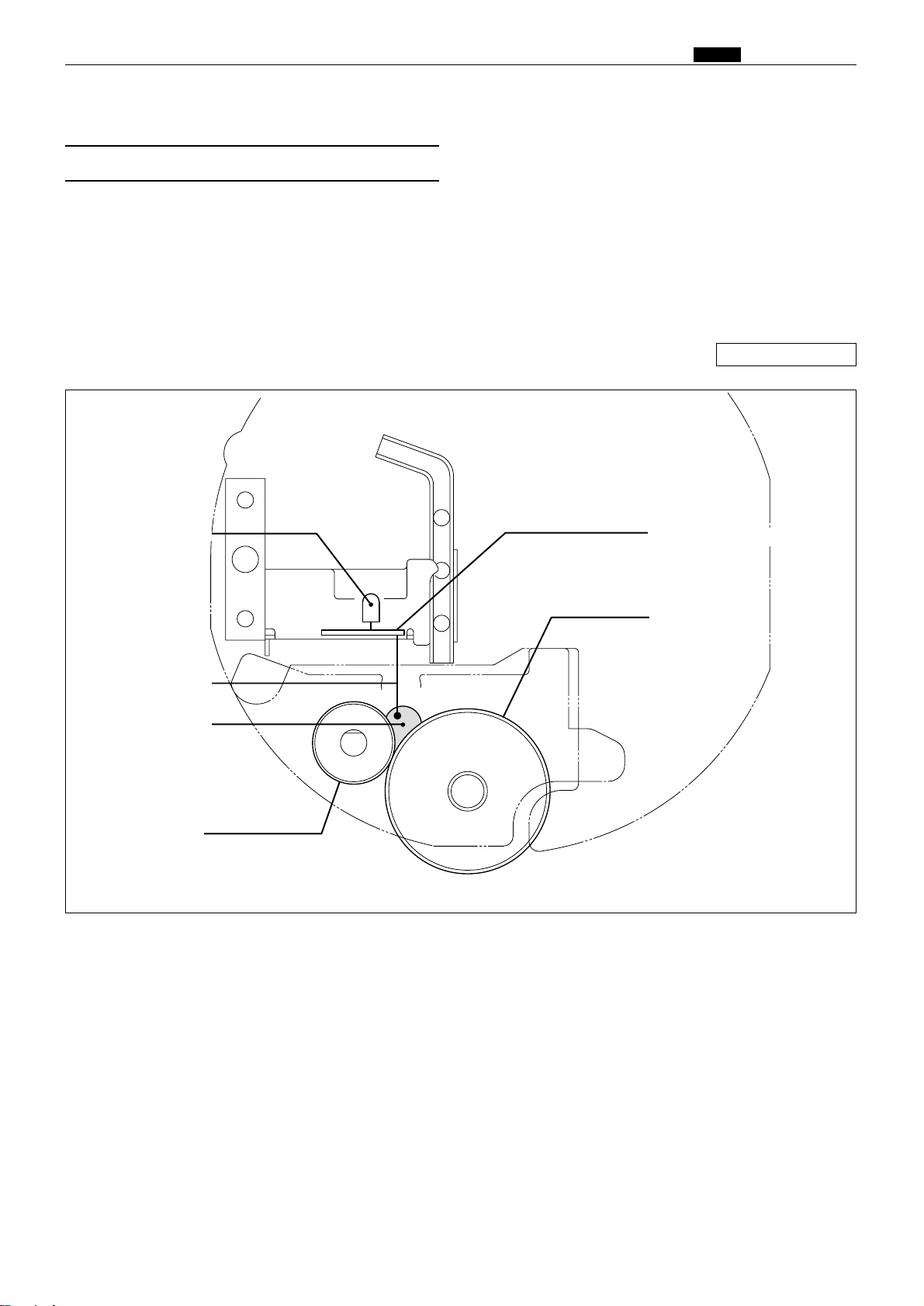
95
m Drum Section
chap.2
Description
The ink amount variation in the ink control section is read by the electric capacity variation between the
detection needles on the ink detection PCB Unit and the GND and the ink signal is output to the main PCB
Unit. The main PCB Unit controls the motor ON and OFF by this signal.
When NO INK continues while the drum rotates 20 times (the number of drum unit rotations; it varies
depending on the printing speed.*) during printing, it is determined that the ink pack is empty, "CHANGE
INK" is displayed and the machine stops printing.
(1) Ink Detection
3. Function of Parts
\See page 97
440332
Ink detection PCB unit
LED
Squeegee roller
Ink roller
Ink
Detection needle
Page 93

96
m Drum Section
chap.2
2Timing of the LED and the ink motor operation is
as follows. The ink motor works during printing
(driving output signal).
Ink detection PCB unit
LED CN1-2
No ink Light out +5V
Ink Light up 0V
2Ink detection PCB unit
Between the CN12-3 and GND
1. LED Display and Output Signal on the Ink
Detection PCB Unit
2When the electric capacity variation between the
detection needles on the ink detection PCB Unit
and GND is over the threshold value, the LED on
the ink detection PCB Unit lights up and the ink
signal (0V) is output.
Page 94
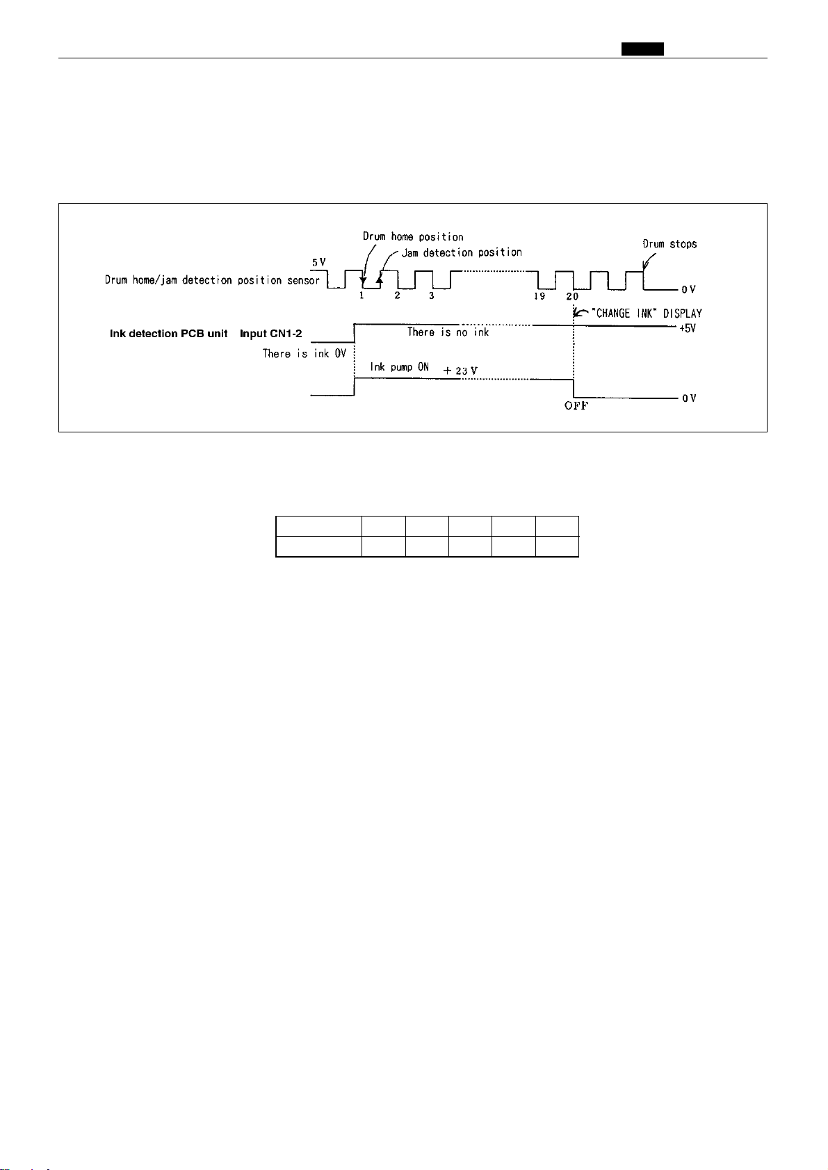
97
m Drum Section
chap.2
2. "CHANGE INK" Display Timing
When HIGH (5V) is output by detecting ink while the drum continues to rotate 20 times (the number of
rotations varies depending on the printing speed.*) during printing, it is detected that the ink pack is empty,
"CHANGE INK" is displayed on the error display, and printing stops. At the same time the power for the ink
motor is turned off.
*The drum rotates until "CHANGE INK" is displayed after HIGH is output from the ink detection PCB unit
during printing. The number of drum rotations varies depending on the printing speed as follows:-
Printing speed
Number of rotations
1
4526838041005120
Drive PCB unit Output CN12-5
Page 95
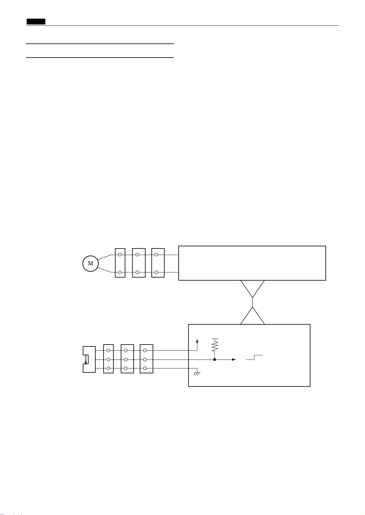
98
m Drum Section
chap.2
Description
At times other than printing, the ink roller is separated from the inner surface of the drum by a fixed
clearance. During printing, however, the press roller rises and presses the ink roller into contact with the
drum inner surface, so that ink is supplied via the drum inner surface to the printing paper. This mechanism
prevents ink from being supplied to the drum inner surface if the printer is run without any paper.
When the master is detached in the platemaking process, ink on the drum surface is removed along with the
document, which means that in the first printing after the master is attached, there is a possibility of
insufficient ink on the drum surface, resulting in faint images.
To prevent such ink insufficiency when in the first printing, the machine is equipped with a mechanism for
raising and lowering the ink roller. Before paper is fed in, this mechanism pushes the ink roller against the
drum inner surface, so that ink is forcibly supplied immediately prior to the start of printing. As a result, the
images on the first sheet printed after platemaking are sufficiently bold.
Ink roller up and down operations are included as elements in the Fine Start mode, together with contact
pressure adjustment, and therefore are optimally controlled in accordance with room temperature, length of
time out of use, number of sheets in last run, etc.
Ink roller up/down sensor
Red
Blue
CN21-131
2
3
-15
Purple
-14
5V
5V
5V
0
CN1-1
-32
CN14-7
-8
Ink roller up/down motor
Brown
White
1
2
3
4
12
24
Drove PCB unit
-
CN3-1
-32
-
1
3
18
19
9
11
2 7 10
Main PCB unit
Photopassing :0V
Photointerrupting:5V
Circuit
(2) Ink Roller Up/Down Mechanism
440W29e
Page 96

99
m Drum Section
chap.2
¡Standby position during printing
Cam is in the bottom position, and the ink roller is
raised up by a spring. The ink roller up/down
sensor is in the state of photopassing(OPEN),
signalling that the ink roller has reached the upper
limit position. In this position, the ink roller is not
touching the drum inner surface.
¡Ink roller descent
The motor turns, and cam pushes the ink roller
downward. When edge plate rotates, the ink roller
up/down sensor is in the state of photointerrupting
(CLOSED), the sensor signals that the roller has
reached the bottom limit position, and the motor
stops. In this position, the ink roller is pressed
against the drum inner surface, and ink will be
supplied even if the machine performs printing
without paper.
¡Ink roller ascent (to standby position)
The motor turns, and when cam reaches the bottom
position, the spring raises the ink roller up. When
the ink roller up/down sensor is in the state of
photopassing, the sensor signals that the roller is in
the raised position, and the motor stops.
Operation
Ink roller up / down motor
Ink roller up / down sensor
Cam
Cam
Spring
440357
440358
440359
440360
Spring
Edge plate
Ink roller
Ink roller up /
down sensor
Drum inner
surface
Edge plate
Cam
Ink roller up / down motor
Ink roller
Photopassing
Drum inner
surface
Photopassing
Photointerrupting
Page 97

100
m Drum Section
chap.2
Description
The ink control section in the drum is supplied with ink in the ink pack by driving the ink motor.
Operation
The piston performs suction and release operation by moving up and down.
When the piston moves up, it draws ink from the
ink pack into the pump.
When the piston moves down, the pump releases
ink.
Mechanical Structure
(3) Ink Pump
440333
440334 440335
Ink motor Ink pump
Page 98
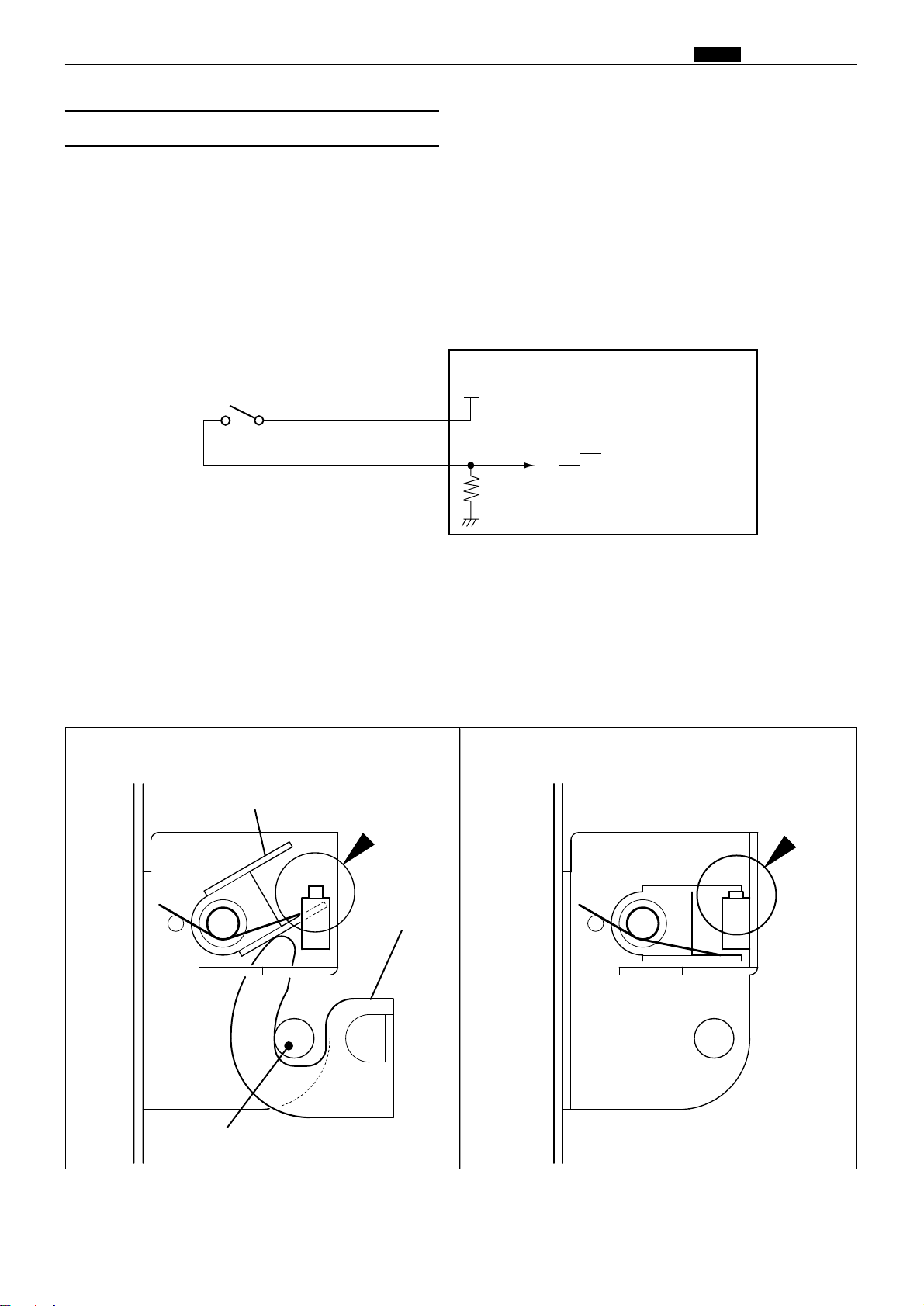
101
m Drum Section
chap.2
Description
The drum switch detects whether the drum is installed to the machine.
When it is detected that there is no drum installed, "NO DRUM" is displayed on the error LCD panel the
machine stops operation. When no drum is detected during operation, all the operations stops emergently.
Operation
When the drum is attached to the main body, the cam unit covers the pin and is locked firmly. The difference
of the cam unit prevents the cam unit from being loosened due to the machine vibration.
When the pin is at the bottom of the cam unit difference, the drum SW is open as shown in the figure. When
the pin is over the cam unit difference, the drum SW is closed.
Drum detection switch
No drum : CLOSE
Drum installed : OPEN
Main PCB unit
White
White
CN4-10
-11
5V
5V
0
No drum : 0V
Drum installed : 5V
Circuit
(4)Drum Detection Switch
Lever
Switch OFF
Pin
Cam unit
440336
2No drum2Drum installed
440W30e
Switch ON
Page 99

102
m Drum Section
chap.2
(5) Fine Start Mode
This mode automatically sets optimum values for the following start conditions: timing of ink roller actuation
during platemaking, number of no-paper rotations with the ink roller actuated, and contact pressure at printing start. These optimum settings are based on room temperature, the length of time the printer was out of
use, and the number of prints last time it was used. They ensure clear printing right from the first sheet after
platemaking.
*Room temperature of 10; or below can cause insufficient ink supply, even in Fine Start Mode.
Standby state The cam turns a half-revolution, so that the ink
roller is pressed against the drum inner surface.
Then the drum rotates.
The cam turns a half-revolution, so that the ink
roller moves out of contact with the drum inner surface.
Printing begins.
Cam
Ink
Roller
Screw
Motor
Drum
Ink roller
Press roller
Spring
Squeegee
roller
Operation
Page 100

103
m Drum Section
chap.2
(6) Drum Shift Mechanism
Description
The printing position (left and right) can be switched automatically via the operation panel. If the position is
changed via the operation panel, the drum shift motor starts moving by turning the PRINT key on.
Operation
Shifting amount of the printing position in the pel path direction is detected by combining the drum center
sensor and the drum limit sensor to detect the standard position by using the drum center senor.
* Operation during plate making
The following operations are performed by pressing the PLATEMAKING key.
When the drum shift motor is rotated clockwise (CW), the drum is shifted from the drum home position to
the plate making position (opposite from the control).
After master setting, the drum is returned to the drum home position by rotating the drum shift motor
counterclockwise (CCW).
Drive PCB unit
Main PCB unit
Pink
Blue
Drum shift motor
-3
-4
Yellow
-5
White
-6
Light green
-2
Black
CN14-1
4
6
2
5
1
3
M
Drum limit sensor
Red
Blue
CN21- 71
2
3
- 9
Glay
- 8
5V
5V
5V
0
131516 3
5
2 4 4
Photopassing :0V
Photointerrupting:5V
Drum center sensor
Red
Blue
1
2
3
-12
White
-11
5V
5V
5V
0
46 5 6 6
8
5 17 7
Photopassing :0V
Photointerrupting:5V
-10
Circuit
Sensor
440W34e
Drum limit sensor
440361
Drum center sensor
Drum shift motor
 Loading...