

Duplo Duprinter DP-43E, Duprinter DP-43S, Duprinter DP-31S, Duprinter DP-33E, Duprinter DP-33S Service Manual
...Page 1

DUPRINTER
DP-43E/S
DP-33E/S
DP-31E/S
V er.2
SERVICE MANUAL
Be sure to read this manual carefully, so that you
repair and service this machine safely and
correctly. Do not begin work until you have
thoroughly understood the contents of this manual.
Repairing or servicing the machine with insufficient
knowledge about it could lead to unforeseen
accidents or falls in the machine's performance or
quality.
DUPLO SEIKO CORP.
Page 2

1
Introduction
The cause of most accidents is failure to adhere to basic safety rules and observe
safety instructions. It is important to prevent potential causes of accidents from
occurring. In order to do so, read this manual carefully, and be sure to understand
all the safety instructions and correct inspection and servicing procedures that it
provides before beginning repair or servicing work.
Repairing or servicing the machine with insufficient knowledge about it could
lead to unforeseen accidents.
It is not possible to anticipate and describe in a manual such as this every possi-
ble hazard that could arise in the course of repair and servicing. Therefore, besides
observing the safety instructions marked in this manual and on the machine's
labels, service personnel should be safety-conscious and take other safety precau-
tions as necessary. When performing repair or service work not covered by this man-
ual, you should obtain safety guidance from an appropriately knowledgeable person.
Copyright c 1999
DUPRO SEIKO CORPORATION
All Rights Reserved
Page 3

2
'Safety-related instructions
'Service work-related instructions
If the instructions accompanying this symbol are ignored and the
machine is operated incorrectly, death or serious injury is likely to
result.
If the instructions accompanying this symbol are ignored and the
machine is operated incorrectly, death or serious injury, or else material
damage, is likely to result.
WARNING:
COUTION:
Examples of pictorial symbols
A " " symbol tells you that a certain action is forbidden. Precisely what
is forbidden is indicated by a picture inside the symbol (in the example
here, the picture means that disassembly is forbidden), or in writing at the
side of the symbol.
A " " symbol means that a certain action is forbidden and/or that a specific instruction must be followed. The specific instruction is indicated by a
picture inside the symbol (in the example here, the instruction is "Remove
the power plug from the socket").
IMPORTANT:
NOTE:
Draws attention to important information. If this information is ignored and
the machine is operated or serviced incorrectly, the machine`s performance could drop, or it could break down.
Draws attention to information that is useful for operation or maintenance
of the machine, and to information about its performance, etc.
D Using the service manual
• This manual contains the following information: structure and function of major parts, disas-
sembly and reassembly procedures, specifications, and procedures for adjustment, mainte-
nance, inspection and corrective action. This information is current as of May 1999, and applies
basically to the model DP-43E/S,33E/S,31E/S Duprinter.
From time to time, parts are changed to improve quality, performance or safety. Note therefore
that in some cases, certain parts or machine structure aspects described in the text or illustra-
tions of this manual may not be precisely the same as the product being serviced.
• Safety instructions marked with a " " (WARNINGS and CAUTIONS) are very important for
safety and must be observed.
Page 4

3
Safety instructions
Safety instructions
Safety instructions
1. Cautions regarding the installation location
Installation environment
• Avoid installing the machine in places exposed to direct sunlight.
• Sunlight will cause the temperature in the machine's interior to rise, possibly leading to mal-
function of the control system.
• Sunlight could cause misoperation of the sensors.
• The heat of direct sunlight could cause deformation of the machine's plastic parts.
* Also avoid installation near to a ground glass window; light and heat penetrate such windows
although they are opaque.
• Avoid installing the machine in places subject to high or low temperature or humidity.
• High or low temperature or humidity could cause the machine to operate abnormally.
Suitable temperature and humidity ranges are:
Ambient temperature: 10y430y
Ambient humidity: 40%470%
Optimum temperature and humidity: 20y, 65%
• If the machine is installed near to faucets, water heaters or humidifiers, or in cool (sunless)
parts of a building or in the vicinity of water sources, the paper could absorb moisture and curl,
leading to misfeeds or poor image quality.
• Avoid installing the machine in places with open flames, or where reflected heat or other hot air
currents (from stoves, etc), or cold air currents from coolers, etc will strike it directly.
• Avoid installing the machine in poorly ventilated places.
• Avoid installing the machine in dusty places.
• The machine should not be tilting when it is used.
• Install the machine so that it is level.
(The machine should be level to within 5mm in the front-rear direction, and 5mm in the lateral
direction.)
•Do not install the machine on shaky, sloping or otherwise unstable surfaces.
• The machine could fall over on such surfaces, or fall off them, causing injury.
Page 5
4
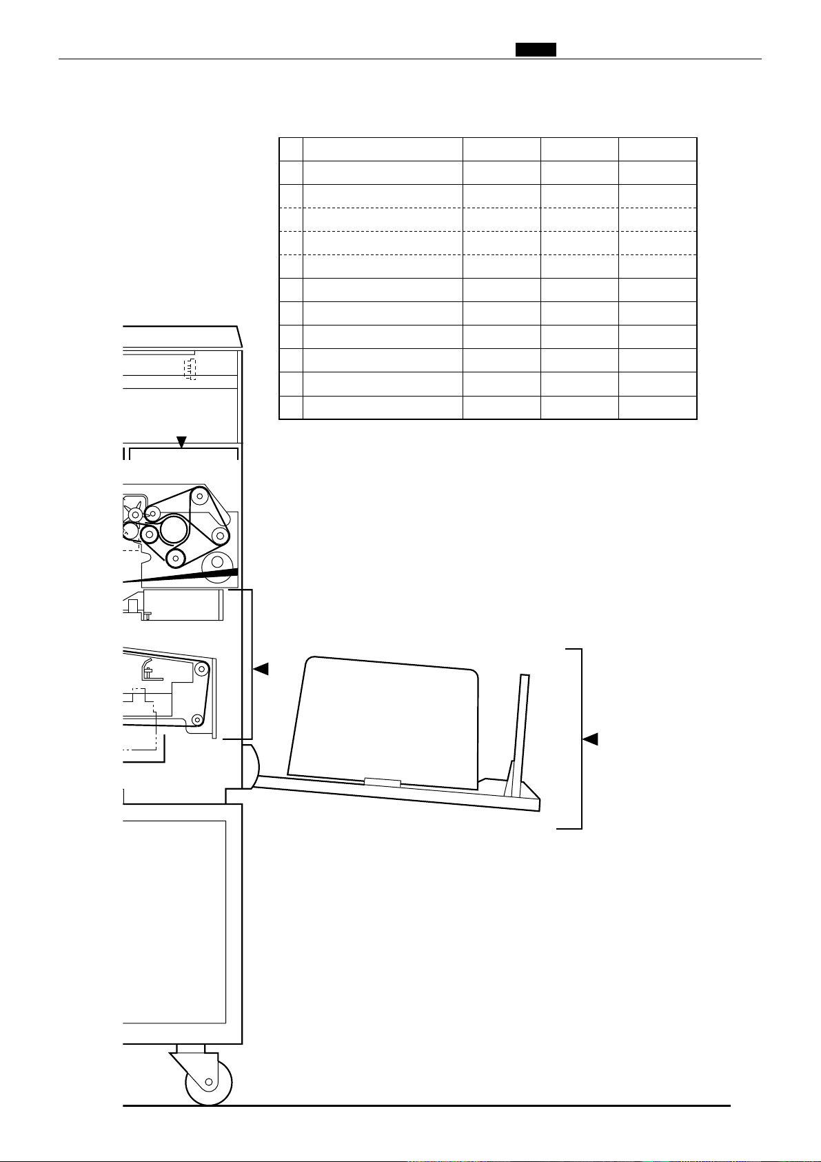
Safety instructions
• The machine's power supply voltage and power consumption depend on the model. Details of this
are given in the tables below. The power supply voltage and power consumption for the machine
are given in the table below. The machine's power supply voltage is indicated on the identification
plate located on the machine's left side; the machine must be connected to a power supply of the
voltage indicated.
a Otherwise, fire or electric shock could result.
If the power supply voltage is unstable or if the power supply has insufficient capacity, the
machine may not operate normally.
Make sure that the power supply has sufficient capacity for the system as a whole, including
optional equipment.
Warning
Connect to outlet of 120V AC, 60Hz, at least 15A
With no load*
At full load
Power consumption
No more than 130V AC
At least 110V AC
During platemaking : 230W
During printing at speed 3 (printing speed) :110W
On standby : 30W
Power supply voltage
}
Use power supply meeting these requirements
Connect to outlet of 230V AC, 50Hz, at least 8A
With no load*
At full load
Power consumption
No more than 250V AC
At least 210V AC
During platemaking : 230W
During printing at speed 5 (printing speed) :300W
On standby : 30W
Power supply voltage
}
Use power supply meeting these requirements
* 120V AC model
* 230V AC model
* "With no load" - when the machine is on standby.
* "At full load" - when the machine is running at maximum power consumption.
• Use only the power cord that is provided among the accessories.
Insert the power cord plug firmly into the socket, so that proper electrical contact is effected.
• Install the machine close to its power supply. The outlet used should be exclusively for the
machine, and have no other equipment connected to it.
If an extension cord is necessary, it should have a ground terminal, and be of the following ratings:
* For a 120V AC model: 130V, at least 15A, length not exceeding 5m.
* For a 230V AC model: 250V, at least 8A, length not exceeding 5m.
• Never tread on the power cord or pinch it between other objects, or accidents could result.
2. Cautions for installation work
• Install the machine in accordance with the installation procedure appended to this manual.
• Lock the casters after the machine is installed.
a Otherwise, the machine could move or fall over, causing injury.
• To move the machine, push it by its mounting base.
a Pushing the printing (upper) part of the machine could make it fall over.
CAUTION
Page 6

5
Safety instructions
' Precautions for safe servicing
• Always remove the power cord plug from the outlet before starting work.
a Otherwise, you could get a shock or your hands/fingers could be injured.
• However, the plug must be left connected to the outlet when performing function checks (of indi-
vidual motors, a given series of operations, or electrical circuits). When motors are operated alone
in function checks, interlocks are deactivated, so be aware of the conditions and positions of relat-
ed equipment, and take great care not to put your hands or fingers into moving parts.
• The cutter unit contains hazardous sharp blades. Exercise great care when inspecting the cutter
unit or replacing it or its parts.
a Otherwise, your hands/fingers could be injured.
• Do not touch the drum or rollers after turning on the jog switch.
• Do not put your hands or fingers inside the machine while the drum is rotating.
a Otherwise, your hands/fingers could get caught and crushed between the drum and rollers.
' Working clothes
• Wear clothing than enables you to work safely.
Work clothing (overalls, etc) should be close-fitting.
Warning
' Tools
• Use tools that are appropriate for the work.
CAUTION
3. Cautions for maintenance, inspection and servicing
Page 7

6
Safety instructions
DLocations of warning stickers
The locations of the machine's warning stickers are shown below. To ensure safe work, read the
stickers and heed their instructions. Keep the stickers clean at all times. If they become damaged
or peel off, replace them with new ones.
No. Parts No. Name Q'ty
q
J3-T3200 Warning Sticker 1 1
w
L5-T3020 Warning Sticker 2 1
J3/-T3200
q
Warning
¡Do not remove this cover. The
inside of the printer contains
movable cutting instruments,
contact with which could result
in injury.
L5-T3020
2
Do NOT touch the drum or rollers
when you operate the jog switch.
Do NOT put hands Inside
machine while it is operatung.
Hands could get caught up
or crushed.
WARNING
Page 8

7
Chapter 8
Chapter 7
Chapter 6
Chapter 5
Chapter 4
Chapter 3
Chapter 2
Chapter 1
HELP Mode
Others
Countermeasures
Installation
Standard / Adjustment
Mechanism
Description of the Operation
Introduction
Page 9

8
Table of Contents
Chapter 1
z Features ................................................................................10
x Specifications ........................................................................14
c Dimensions ...........................................................................16
v Mechanism............................................................................17
b Master ...................................................................................18
n Ink .........................................................................................19
m System Setup ........................................................................20
, Part Names and Their Functions ........................................21
. Operation Procedures ..........................................................34
⁄0 Error Messages and Corrective Action ...............................38
⁄1 Option ...................................................................................60
Chapter 2
z
Scanner Section ..........................................................86
x
Platemaking/Master Feed/Ejection Section..............94
c
Paper Feed Section...................................................115
v
Drum Driving Section ..............................................129
b
Press Section.............................................................135
n
Paper Ejection Section .............................................142
m
Drum Section............................................................148
,
Option .......................................................................160
Chapter 3
z
Exterior .....................................................................164
x
Scanner Section ........................................................172
c
Platemaking/Master Feed/Ejection Section............180
v
Paper Feed Section...................................................188
b
Drum Driving Section ..............................................192
n
Paper Ejection Section .............................................194
m
Drum Section............................................................202
Chapter 4
z
Scanner Section ........................................................212
x
Platemaking/Master Feed/Ejection Section............214
c
Paper Feed Section...................................................222
v
Drum Driving Section ..............................................229
b
Press Section.............................................................231
n
Paper Ejection Section .............................................233
m
Drum Section............................................................235
,
Electrical System......................................................239
.
Option .......................................................................249
Chapter 5
z
DUPRINTER installation instructions...................252
x
Drum unit installation instructions........................262
c
KEYCARD COUNTER 3 installation procedure....266
v
A4 DRUM installation procedure............................270
Chapter 6
z
Troubleshooting Guide.............................................272
x
Error Display............................................................283
Chapter 7
Chapter 8
z
Electrical Parts Layout and Their Functions .........366
x
Overall Timing Chart...............................................375
c
Overall Wiring Layout
E type models...........................................................377
S type models ...........................................................378
z
HELP Mode List.......................................................286
x
Overview ...................................................................290
c HELP Mode Functions and Operation Procedures
........291
(1)Basic Procedure for Accessing HELP Modes ......291
(2)Guide to the HELP Mode Descriptions ...............291
• HELP Mode Descriptions.....................................292
Introduction.................................................................................1
Using the service manual ...........................................................2
Safety instructions ................................................................3
1.Cautions regarding the installation location.........................3
2.Cautions for installation work................................................4
3.Cautions for maintenance, inspection and servicing ............5
• Locations of warning stickers.................................................6
Countermeasures
Installation
Standards / Adjustment
HELP Mode
Others
Mechanism
Description of the Operation
Introduction
Page 10

9
Chapter 1 Introduction
z Features ........................................................................10
x Specifications................................................................14
c Dimensions ...................................................................16
v Mechanism....................................................................17
b Master ...........................................................................18
n Ink .................................................................................19
m System Setup................................................................20
, Part Names and Their Functions................................21
1. Machine exteriors ....................................................21
2. Sectional (structural) view of the machine.............24
3. Control Panel
E type models...........................................................26
S type models ...........................................................30
. Operation Procedures...................................................34
1. Printing
E type models...........................................................34
S type models ...........................................................35
2. Multiple Image Printing / 2 IN 1 Layout Mode
E type models...........................................................36
S type models ...........................................................37
⁄0 Error Messages and Corrective Action........................38
1. Error messages.........................................................38
2. Corrective action ......................................................41
(1) Replacing the Ink Pack ......................................41
(2) Replacing the Master Roll .................................43
(3) Replacing the Master Ejection Core..................46
(4) Supplying Paper ................................................48
(5) Replacing the Drum Unit ..................................51
(6) Paper Jam (Feeder side) ....................................53
(7) Paper Jam (Ejection side) ..................................54
(8) Master is Not Ejected.........................................57
(9) Master Set Incorrectly .......................................59
⁄1 Option............................................................................60
1. DUPRINTER Opion.................................................60
(1) TAPE CLUSTER 3 .............................................60
(2) KEYCARD COUNTER 3 ...................................61
(3) A4 DRUM (for DP-43E/S) ..................................80
1
Page 11

Chap.1 z Features
zFeatures
1. Size A3 printing
The DP-43E/S has size A3 (290X410mm)
printing area.
The DP-33E/S and DP-31E/S has size B4
(250X350mm) printing area.
2. High-speed platemaking
With the DP-43E/S, it takes 17 seconds
*2
print the first sheet of paper
(size A3).
With the DP-33E/S and DP-31E/S, it takes
*1
15 seconds
*2
paper
*1: Time required to print the first sheet of paper
after the platemaking key is pressed.
*2: When the Fine Start mode is not activated.
to print the first sheet of
(size A4).
3. High print quality
A new, originally-developed superfine thermal head gives beautifully accurate reproductions of fine print and halftone photographs.
Resolution is 400dpi in the DP-43E/S,and
DP-33E/S.
*1
to
Resolution is 300dpi in the DP-31E/S.
4. Simple operation
In the E series, a touch panel provides simple
operation.
In the S series, operation is simplified by concealing occasionally-used keys under a panel,
leaving just the basic function keys permanently accessible.
5. Fine Start Mode
This mode automatically sets optimum values for the following start conditions: timing of ink roller actuation during platemaking, number of no-paper rotations with the
ink roller actuated. These optimum settings
*3
are based on the room temperature
, the
length of time the printer was out of use, and
the number of prints last time it was used.
They ensure clear printing right from the
first sheet.
*3: Room temperature of 10ºC or below can cause
insufficient ink supply, even in Fine Start
Mode.
6. High-performance lamp
A long-life, high-brightness xenon arc lamp
is used to illuminate the documents. Since
the lamp's intensity is not affected by tem-
*4
perature variation
temperatures is greatly enhanced
*4: The lamp is filled with xenon gas, which means
that it does not require heat to vaporize mercury, as a fluorescent lamp does, and therefore its intensity does not vary with temperature.
*5: Increased viscosity of the ink at low tempera-
tures results in fainter printing than at normal temperatures.
, printing quality at low
*5
.
10
Page 12

Chap.1 z Features
7. Full range of necessary functions
qDocuments are easily enlarged or re-
duced.
In addition to same-size printing, there are
three automatic settings for both enlargement and reduction. The margin function
(94% reduction) can be used with any setting.
• Size A/B models
• Free ratio setting (50-499%)
• Auto zoom settings
(70, 81, 86, 115, 122, 141%)
• Same-size (100%) printing
141% [A4/A3, B5/B4]
Enlargement
122% [A4/B4]
115% [B4/A3]
*6
86% [A3/B4]
Reduction
81% [B4/A4]
70% [A3/A4, B4/B5]
• Inch size model
• Free zoom range 50 to 499%
zoom (64, 74, 77, 121, 129, 141%)
• Same-size (100%)
141%
Enlargement
129% [LTR/LDG]
121% [LGL/LDG]
*6
*6
Reduction
77% [LGL/LTR]
74% [LDG/LGL]
67% [LDG/LTR]
*6: Maximum printing area of DP-33E/S and DP-
31E/S is B4(250X350mm).
wEditing functions
Editing functions are standard features of
E series printers (DP-43E,DP-33E,DP31E).
eMemory functions
The printers have memory functions that
can memorize frequently-used settings.
ySelf-diagnosis
The machines have self-diagnostic functions. Messages for self-diagnosed errors,
as well as consumable part replacement
prompt messages, appear on an LCD
panel.
uDocument modes
To the pre-existing Text and Photograph
Modes have been added the "Text-Photograph", "Text-Fine Lettering", "Photograph-Fine Lettering", "Screen 1 & 2" and
"Photo Dark" Modes, accommodating
printing of a wider variety of documents.
*6
Text-Photograph Mode:
Intermediate between the Text and Photograph Modes, this Mode is for documents
with mixed photographs and text.
Text-Fine Lettering Mode:
Emphasizes letter outlines more than the
regular Text Mode, providing better reproducibility of fine lettering.
Photograph-Fine Lettering Mode:
Emphasizes shape outlines more than the
regular Photograph Mode, providing better reproducibility of fine lines.
Screen Modes 1 & 2:
Add dots to images produced by the Photograph Mode, to bring out the contrast.
Mode 1 uses larger dots than Mode 2.
Photo Dark Mode:
Increases the number of gradations in
bright halftone portions of images produced by the Photograph Mode, to prevent
over-bright reproduction of bright documents.
iError message display
An LCD panel displays error messages and
messages prompting replenishment of
consumables.
DP-43E,33E,31E
3 types
DP-43S,33S,31S
2 types
rMultiple image printing
Multiple images (2, 4 or 8) of a single document can be printed on a single sheet of
paper.
tBook shadow erasure
Shadows in the middle or at the edges of
book documents can be erased.
11
Page 13

Chap.1 z Features
oSpecial functions
The following functions/modes, which formerly could only be changed/used by service personnel, have been made into user
functions/modes.
• Auto Clear
• Preprint
• Print Number Input Mode
• Change Initial Setting
• Fine Start
!0Adjusting the Printing Position
(vertical /horizontal)
In addition to vertical direction
adjustment,there is now a function for
adjusting the printing position in the horizontal direction as well.
!12 in 1 Layout Mode
In conjunction with an ADF (optional), this
mode makes possible continuous printing
of 2 documents onto single sheets of paper.
8. Options
qADF
Use of the ADF permits continuous platemaking and printing of 30 documents (64g/
2
paper). The ADF's tray fits completely
m
inside the ADF, so as not to interfere with
loading/removal of printing paper.
wTape cluster
This permits sectionized printing, by inserting tape automatically during printing.
eKey card counter
This magnetic card can control the numbers of prints and platemakings by up to
200 sections.
NOTE: Without this optional counter, the
number of sections controlled is 30 (standard).
rDrums
Replacing the drum with optional drums
permits printing with different colors.
!2Key card counter
Raises the number of sections controlled
*7
to up to 200
. Versions with internalized
control panel also available.
*7: Standard: 30 sections. Using the counter (op-
tional) raises the number to 200 sections.
tSorter
The newly-developed 25-bin tandem sorter
can sort up to 50 sets of sheets. A stapler
can be installed to staple the sets after
sorting.
yOn-line functions
*8
These enable data processed on a personal
computer or word processor to be directly
input and used for platemaking/printing.
*8: These functions require an IPC I/F kit and PC
interface.
12
Page 14

MEMO
Chap.1 z Features
13
Page 15

Chap.1 x Specifications
xSpecifications
• Specifications
Product name/model No.
Model Floor model
Platemaking method Thermal digital platemaking
Platemaking interval
Resolution 15.7 dots/mm (400 dpi)
Scanning method Fixed document
Printing method Stencil printing
Document type Sheet, Book (less than 10 kg)
Document size
Printing area
Feeding capacity 1000 sheets (64 g/m
Stacking capacity 1000 sheets (64 g/m2, duodecimo 55kg,high-grade paper)
Paper size
Paper thickness 53 g/m
Printing speed 120 pages par minute. (45 to 120 pages par minute, 5 step adjustment)
Print enlargement/reduction
A, B size model Same size 100%
Inch size model Same size 100%
Printing position adjustment
Image modes Text mode / Photograph mode / Text and photograph mode /
Contrast control Platemaking density 5 step adjustment
Ink supply method Complete automatic control (600 cc, 1000 cc)
Color printing Drum unit exchange method
Master feeder Roll master automatic feed
Plate ejection Complete automatic ejection plate rolling method
Power source
120VAC model 120VAC 60Hz, 5A
230VAC model 230VAC 50Hz, 2.5A
Power consumption
Size Operational Idle
Weight
Operating temperature
※ Specifications are subject to change without notice.
DP-43E / DP-43S DP- 33E / DP-33S
17 seconds (A3, same size)
Max. 297 mm×432 mm
Max. 290 mm×410 mm
2
, duodecimo 55kg,high-grade paper)
Max. 297 mm×432 mm (A3: 11” × 17”)
Min. 100 mm×150 mm (postcard)
2
to 210 g/m2(45 kg to 180 kg)
Fixed zoom ratios 70, 81, 86, 115, 122, 141%
Print with border 94%
Free zoom range 50 to 499%
Auto zoom 70, 81, 86, 115, 122, 141%
Fixed zoom ratios 64, 74, 77, 121, 129, 141%
Print with border 94%
Free zoom range 50 to 499%
Auto zoom 67, 74, 77, 121, 129, 141%
Vertical ±15 mm
Horizontal ±10 mm
Finelettering / Screen / Photo dark, Multiple printing (2, 4, 8 up)
Book shadow eraser
Printing density 3 step adjustment
230W(during platemaking), 110W(during3-speed printing),
30W(during standby)
1288mm(W)×670mm(D)×652mm(H)
675mm(W)×670mm(D)×652mm(H)
(cabinet height 350mm)
Machine 103kg
Base 12kg
10Y430Y
15 seconds (A4, same size)
Max. 250 mm×350 mm
1288
mm
(W)×655mm(D)×652mm(H)
675
mm
(W)×655mm(D)×652mm(H)
(cabinet height 350
Machine 96kg
Base 12kg
DP-31E / DP-31S
11.8 dots/mm (300 dpi)
mm
)
14
Page 16

• Specifications
Display panel
DP-43E/DP-33E/DP-31E DP-43S/DP-33S/DP-31S
320×240 dots, full dot matrix
LCD with Touch Panel (pressure
sensitive) input capabilities.
240×64 dots, full dot matrix LCD
Chap.1 x Specifications
Input
Strength
LCD
Recommended
viewing angle
range
Editing Functions
Other standard functions
※ Specifications are subject to change without notice.
Trimming
Makeup
Photograph Mode, Reversing,
Masking, Outline Type, Halftones,
Background Designs, Reversing
Background Designs, Mask Area
Exchange, Addtional Makeup
• OK monitor (graphical display,
Kanji characters/illustration
display)
• Memory ( 3 channels)
• Confidential Safeguard Function
• Entry of different number of
prints or sets
• Special function
• Fine start mode
By fingertip or special pen
Able to withstand maximum 29.4N (3kgf), a pplied
perpendicularly to the tablet surface for 1 minute
Recommended operating temperature: 0Y4 40Y
Vertical: up to 30Y above/below perpendicular
Horizontal: up to 30Y to either side of perpendicular
• OK monitor (graphical display,
Kanji characters/illustration
display)
• Memory ( 2 channels)
• Confidential Safeguard Function
• Entry of different number of
prints or sets
• Special function
• Fine start mode
• Option specifications
DUPRINTER DP-43E/DP-33E/DP-31E/DP-43S/DP-33S/DP-31S
Options
PC interface kit
※ Specifications are subject to change without notice.
ADF (Automatic Document Feeder)
Drum unit ,A4 Drum(DP-43E/S)
Keycard counter (built-in type)
Tape cluster
Sorter
PC interface kit
The printer driver must be installed in the PC.
• Compatible with Windows95 / Windows98
• Macintosh compatibility
(System 7.1 or later, MAC OS or later)
I/F board in main unit (on-line set III board unit)
SCSI cable (4 m)
15
Page 17

Chap.1 c Dimensions
cDimensions
103
DP-43E/S
DP-33E/S,31E/S
85
490(DP-43E/S)
675(DP-43E/S)
478(DP-33E/S,31E/S)
653(DP-33E/S,31E/S)
437
135
533(DP-43E/S)
513(DP-33E/S,31E/S)
1002
962
350
215 620 453
1288
(mm)
16
Page 18
vMechanism
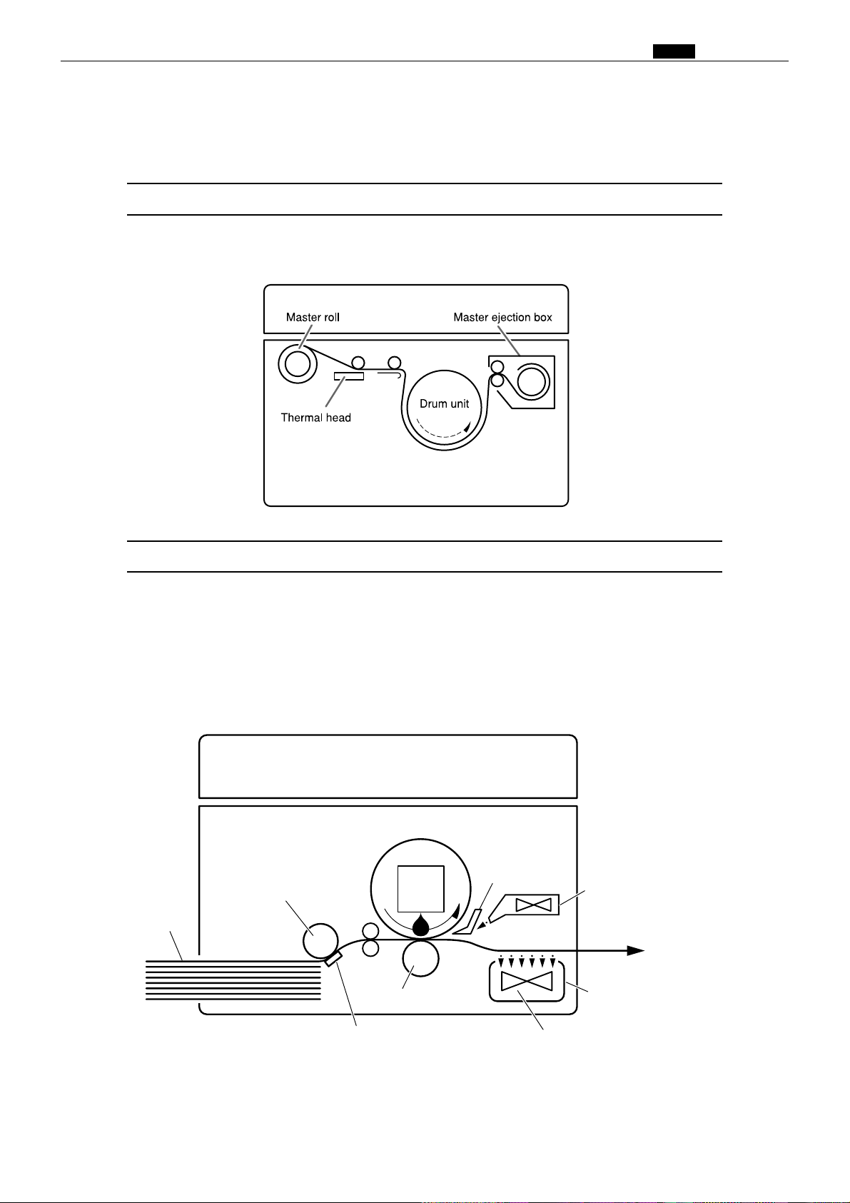
The machine carries out the processes of “platemaking” and “printing.”
Platemaking
In the “platemaking” process, the old master on the drum is removed while the
thermal head creates the scanned image on the new master and transfers it onto the
drum.
Chap.1 v Mechanism
Printing
In the “printing” process, paper separated from the stack by the paper feed roller and
the paper separator unit is pressed against the drum unit by the press roller. There are
small holes over only the image area of the master that is attached to the drum, and ink
that seeps from these holes is transferred to the paper. The paper is then peeled from
the master by the paper stripper finger and the top blow fan. The paper is directed onto
the paper ejection belt by a fan unit and discharged from the machine.
Drum unit
Paper stripper
finger
Top blow fan
Paper
Feeder roller
Ink
Press roller
Paper separator unit
17
Paper ejection belt
Fan unit
Page 19

Chap.1 b Master
bMaster
1) Characteristics of the master
(1) Structure of the thermal master
(2) Functions and materials of the layers
Coated surface …… Prevents the film from fusing, being damaged due to friction,being peeled,
and being conveyed defectively due to electric static charge.
Material: silicon fluorine mold lubricant
Thermal film …… Holes are made by the heat of the thermal head.
Material: Polyethylene terephthalate (polyester)
Adhesive ………… 1] Adheres the film to the base.
2] Does not prevent ink from seeping.
3] Increases impression endurance.
Base ……………… 1] Base material for the master. Fibrous layer
2] Ink seeps the base.
(3) Cross section of the master during platemaking
Holes are made on the coated surface, thermal film and adhesive, while base fiber, base material
for the master, is left.
A part of the film fused by the thermal head is stuck to the head or banks up.
(4) Printed image
As the image consists of innumerable dots, it is taken as a continuous line through our eye.
INPORTANT :
•Precautions to be taken in dealing in the master.
(1) Do not put a heavy thing on the box in which masters are packed.
•This may damage the master and may cause defective platemaking.
(2) Do not leave the master as it is after it is taken out.
•Foreign objects are stuck to the master and this may cause defective platemaking.
(3) Keep the master from direct sunlight, too high or low temperature and too high or low humidity.
(Desirable storage temperature and humidity: 5-35 °C, 20-80%)
• If the master curls, defective plate attachment may occur.
18
Page 20
Chap.1 n Ink
nInk
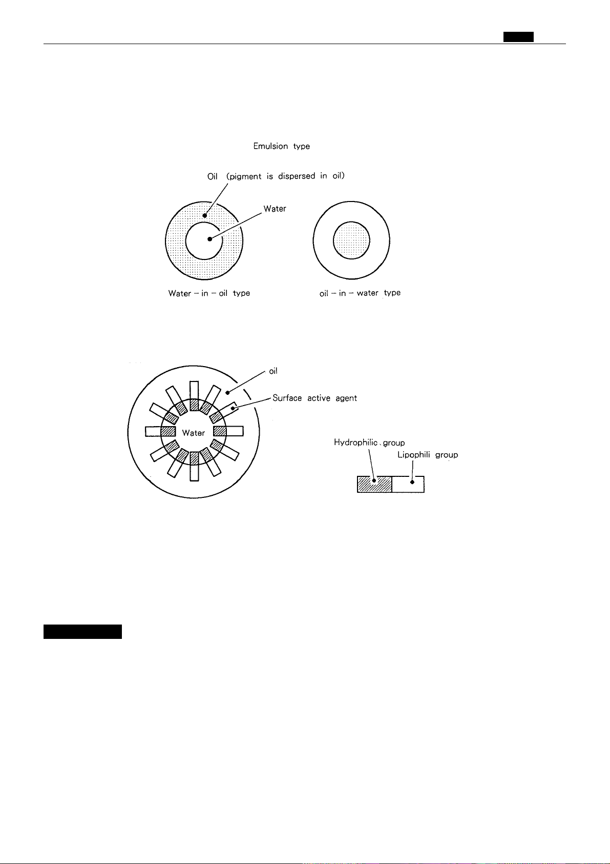
1) Characteristics of ink
(1) Ink for the digital printer is an emulsion type. It has a water-in-oil type structure.
(2) The surface active agent has two characteristics: hydrophilic group and lipophilic group in one molecule.
Oil and water bond together by these two characteristics as shown in the figure.
(3) Ink
(3) Ink viscosity is high at a low temperature and it is low at a high temperature. So when ink is used at a
low temperature (10°C or less), the amount of ink transferred to the paper is smaller and the print
darkness is slightly lighter.
When ink is used at a high temperature (30°C or more), the amount of ink transferred to the paper is
larger and the print darkness is slightly darker.
INPORTANT :
• Precautions to be taken in handling ink
(1) Storage environment
• When an emulsion type ink is stored at too high or low temperature for a long time, oil and water in the
ink pack may be isolated. Keep the ink from too high or low temperature (5°C or less, 35°C or more).
Also keep the ink from direct sunlight since the temperature rises sharply in the direct sunlight.
• When the water content is frozen, the water content is solidified and the bond characteristics decreases.
• When ink is stored at a high temperature, the bond characteristics decreases due to the change of the
surface conditions (surface tension, solubility). The bond characteristics also decreases due to evaporatin
of the water content.
(2) Precautions to be taken in handling the ink pack
• When the ink pack is removed from the drum unit to store, put the ink pack with its mouth up, screw
the cap firmly after expelling air from the ink tube. (If air is in the ink pack, water content is generated.)
19
Page 21

Chap.1 m System Setup
mSystem Setup
The machine and its optional equipment are set up as follows:
ADF
Sorter
Dupulo Direct Print System
Personal computer
Key card counter
Drum unit
Tape cluster
Exclusive machine base
: Option
NOTE
• DDP system
Documents prepared on a personal computer can be printed on this machine. The
IPC board and PC interface kit are required to connect this machine to a personal
computer.
20
Page 22

,Part Names and Their Functions
1. Machine exteriors
Chap.1 , Part Names and Their Functions
21
Page 23

Chap.1 , Part Names and Their Functions
Thermal head escape lever
Master set switch
Master holder
Roll master
Paper tray
descending
switch
Lever
Scanner unit
(
Top cover
)
Paper tray descending switch
Feed pressure switching lever
Paper guide
Paper feed roller
Paper
tray
Supplemental paper tray
(Feeder tray)
Paper guide lock lever
Printing position adjustment dial
22
Page 24

Chap.1 , Part Names and Their Functions
Master ejection core
Master ejection box
release lever
Jamp stands
Master ejection box lid
release lever
Master ejection box lid
Master ejection box
Paper stacker guide
Paper stopper
Drum rotator switch
Print tray
23
Page 25
Chap.1 , Part Names and Their Functions
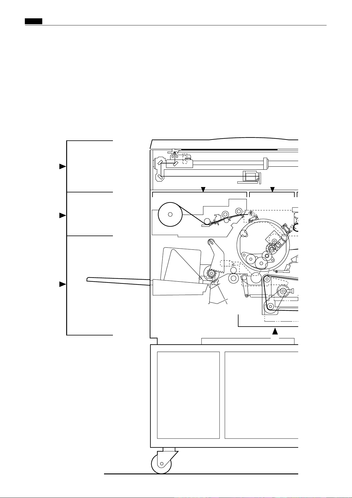
2. Sectional (structural) view of the machine
1
2A
2C
2
3
5
24
Page 26
Chap.1 , Part Names and Their Functions
2B
No.
Section Name
1
Scanner section
Platemaking/Master feed/ejection section
2
Platemaking/Master feed section
2A
Master ejection section
2B
Master clump opening/closing section
2C
Paper feed section
3
Drum driving section
4
Press section
5
Paper ejection section
6
Print tray
7
Drum section
8
Description of
the Operation
86page
94page
94page
107page
109page
115page
129page
135page
142page
4
148page
Mechanism
172page
180page
180page
185page
186page
188page
192page
4
194page
4
202page
Srandard/Adjustment
212page
214page
214page
215page
217page
222page
229page
231page
233page
4
235page
4,8
6
7
25
43E00001
Page 27
!091
2
3
4
5
678
EDIT
F-SET
MENU
PRINTING
1
×
A4
100%
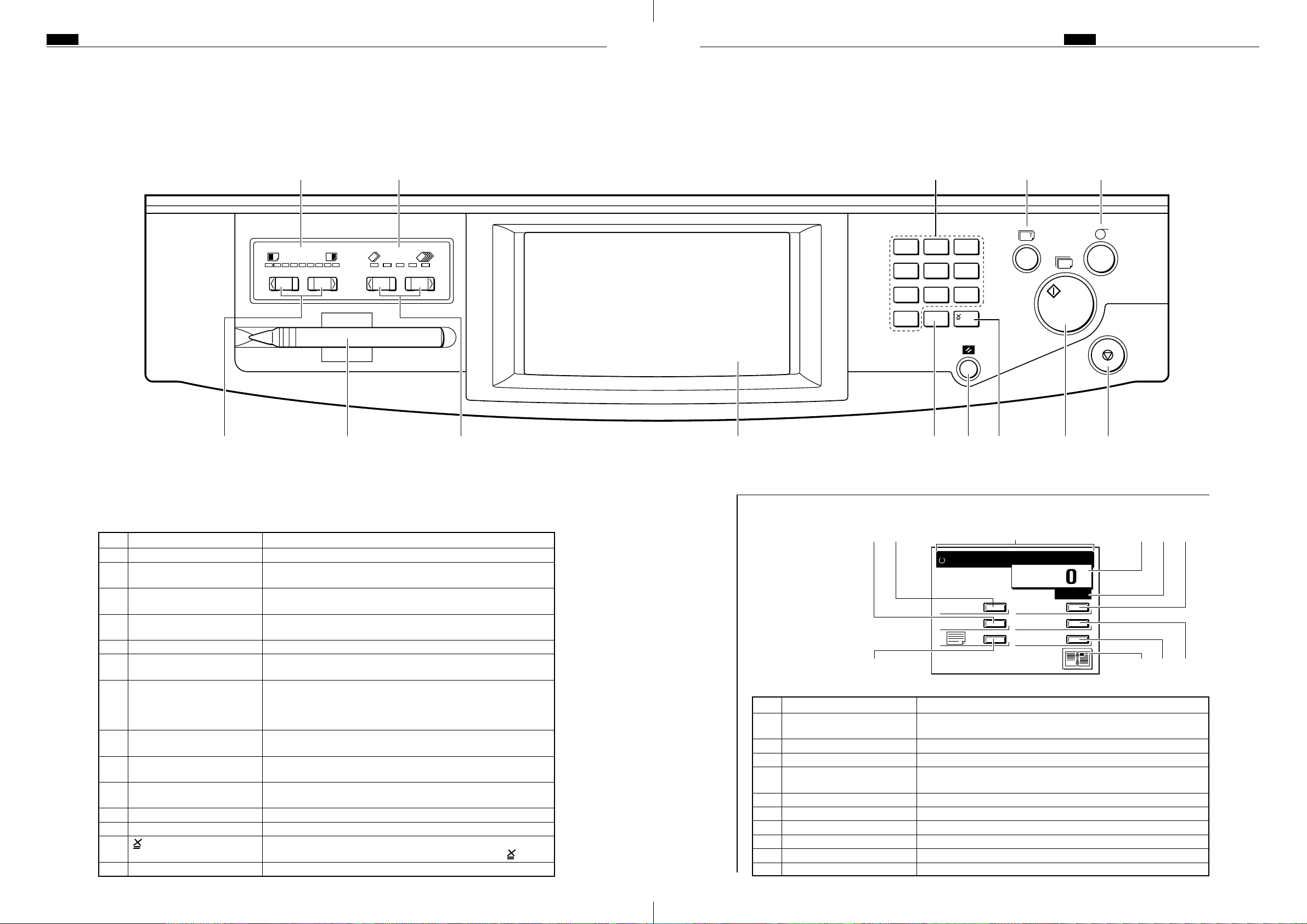
3. Control panel
<<E type models>>
1. Keys of the control panel
Chap.1 , Part Names and Their FunctionsChap.1 , Part Names and Their Functions
e q !1 y t
1 2 3
4 5 6
7 8 9
0 C
No. Name Functions
Printing speed indicator lamp
q
“PRINTING SPEED The printing speed is adjusted with these keys.
w
ADJUSTMENT” keys
Printing position indicator The lamp for the specified printing position lights.
e
lamp
“PRINTING POSITION The printing position (vertical) is adjusted with these keys.
r
ADJUSTMENT” keys
“PLATEMAKING” key Starts platemaking.
t
“TEST PRINT” key Prints one copy. This is used to check the image position and
y
“PRINT” key Starts printing. This will not start platemaking. When the tape
u
“STOP” key Stops printing. If this key is pressed while the machine is
i
“ALL CLEAR” key Returns the control panel settings back to the standard made.
o
LCD panel Displays number of prints and other machine settings. Displays
!0
Key pad Used for entering the number of prints.
!1
“CLEAR” key Clears the display to “0”. Clears the number of prints only.
!2
!3
Input Pen Used with the Edit Functions.
!4
key Enters the number of prints and number of sets. To enter the
The lamp for the specified printing speed lights.
contrast.
cluster or ADF have been installed, platemaking will start
automatically after end of printing if the document is placed on
the ADF .
stopped, the number of copies and plates will be displayed.
Hold down for at least 0.5 second.
error messages when error is occurred.
number of prints per document after a clear, press the key.
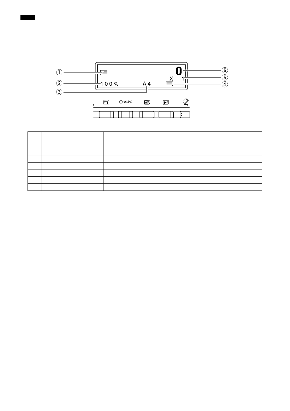
2. LCD Panel main screen
No. Name Functions
Message Display Area Displays "PRINT" and other messages related to the operation of
q
the printer.
Paper Size This button is used to select the size of the paper for printing.
w
Enlargement/Reduction This button is used to set the enlargement/reduction ratio.
e
Photograph Mode This button is used to set the Photograph Mode and other
r
Edit This button is used to select Editing Functions.
t
F Settings This button is used to select Function modes.
y
Menu This button is used to display and manipulate the Menu Screen.
u
Status This button displays the current settings.
i
Counter Displays the number of copies remaining to be printed.
o
Number of Sets Displays the number of sets.
!0
Platemaking methods.
2726
iuo!2 !3!0wr!4
Page 28

Chap.1 , Part Names and Their Functions
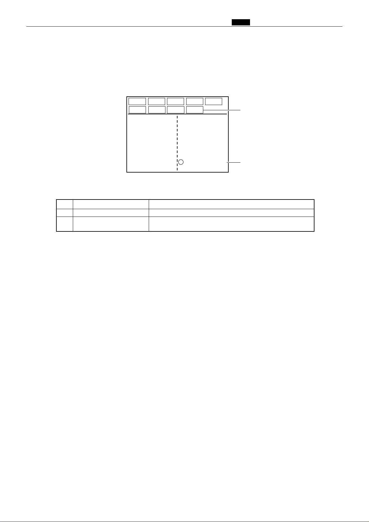
3. Function Mode Screen
Screen A
o Function Keys (F1-F3)
Normal key q
Page Cgange key w
Save key e
No. of Copies/No. of Sets indicator r
Paper Size indicator t
Document Mode indicator y
Enlargement/Reducation indicator u
94% indicator i
No. Name Feature
Normal key Clears the Function Mode.
q
Page Change key Changes from Screen A to Screen B and vice versa.
w
Save key Stores settings under Function keys F1 through F3.
e
No. of Copies/No. of Sets indicator
r
Paper Size indicator Indicates the Paper Size setting.
t
Document Mode indicator Indicates the Document Mode setting
y
Enlargement/Reduction indicator
u
94% indicator A black dot "•" indicates the 94% Reduction Mode is ON.
i
Function Keys (F1-F3) Allow information pertaining to enlargement/reduction, paper
o
End key Terminates Function setting operation.
!0
Clear key Clears settings stored in memory under Function Keys F1-F3.
!1
Plate Darkness indicator Indicates the Plate Darkness (contrast) setting.
!2
Print Darkness indicator Indicates the Print Darkness setting
!3
Trimming indicator A black dot "•" indicates the Trimming Mode is ON.
!4
Makeup indicator A black dot "•" indicates the Makeup Mode is ON.
!5
Book Shadow Eraser indicator
!6
Sorter indicator Indicates the Sorter Mode setting. (Indicator only functions when
!7
Multiple Printing indicator Indicates the Multiple Printing Mode setting.
!8
NORMAL
PAGE
0 ✕ 1
F 1 F 2 F 3
SAVE CLEAR
A 4
100%
✕ 94%
END
!0 End key
!1 Clear key
!2 Plate Darkness indicator
!3 Print Darkness indicator
!4 Trimming indicator
!5 Makeup indicator
!6 Book Shadow Eraser indicator
!7 Sorter indicator
!8 Multiple Printing indicator
Indicates the number of copies and sets that have been set.
Indicates the Enlargement/Reduction setting.
size, multiple printing, number of copies, makeup, etc. to be
stored in advance, and then called up as needed for printing
operations.
Pressing the Clear key returns the Function Keys to their default
settings.
A black dot "•" indicates the Book Shadow Eraser Mode is ON.
the sorter is hooked up.)
28
Page 29
Screen B
Chap.1 , Part Names and Their Functions
NORMAL
PAGE
1: 1 ✕ 1
2: 2 ✕ 2
3: 3 ✕ 3
4: 4 ✕ 4
5: 5 ✕ 5
6: 6 ✕ 6
7: 7 ✕ 7
8: 8 ✕ 8
F 1 F 2 F 3
SAVE CLEAR
MODIFY
9: 9 ✕ 9
A: 10 ✕ 10
B: 11 ✕ 11
C: 12 ✕ 12
D: 13 ✕ 13
E: 14 ✕ 14
F: 15 ✕ 15
NUMBER OF PRINTS
END
!9
@0
No. Name Feature
Modify key Allows the No. of Copies/No. of Sets to be revised.
!9
Number of Prints
@0
A black dot "•" indicates that the Print Number Input Mode is
NUMBER.
29
Page 30
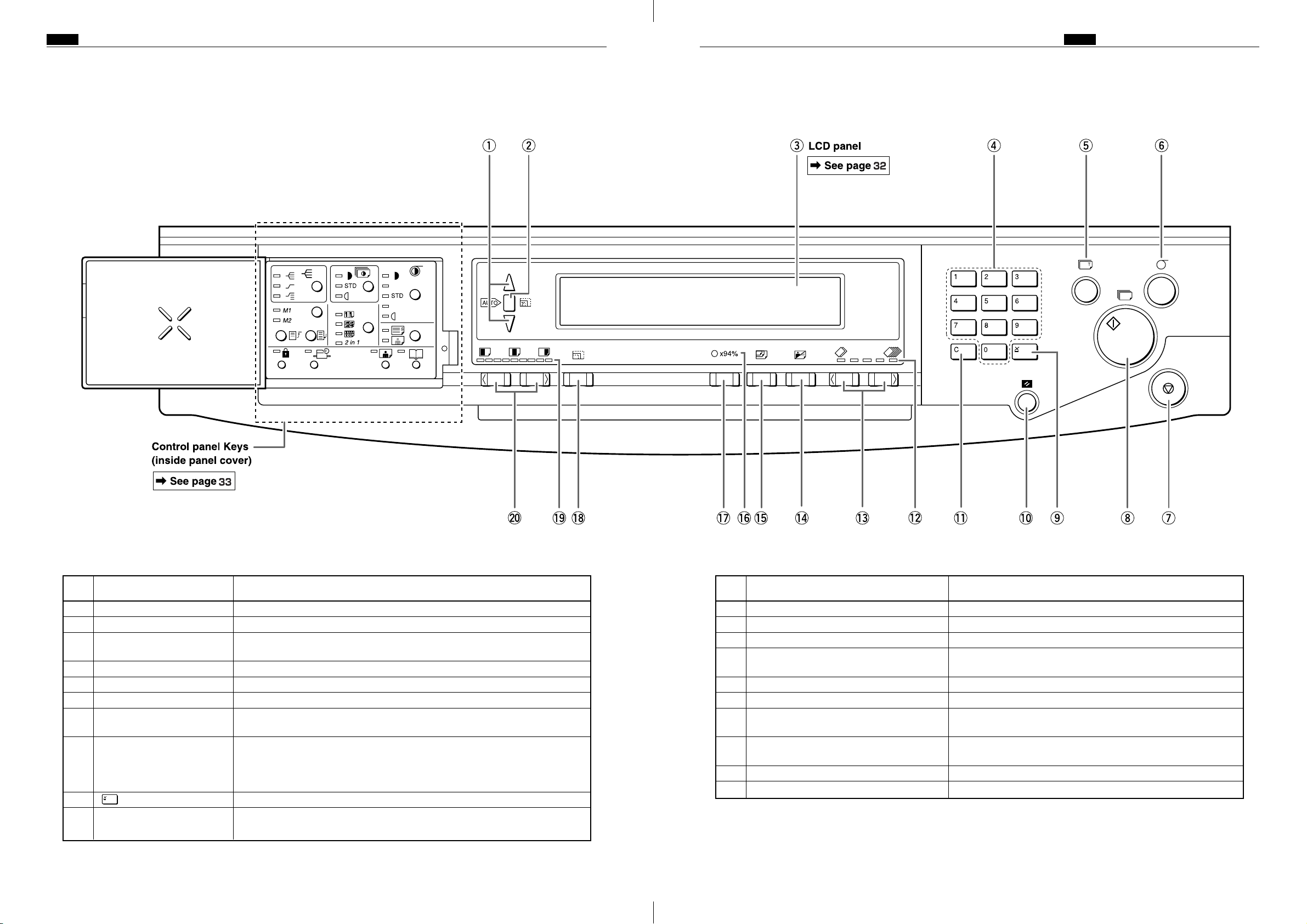
<<S type models>>
1. Keys outside of the panel cover
Chap.1 , Part Names and Their FunctionsChap.1 , Part Names and Their Functions
No. Name Function
q “ZOOM” key Adjusts the zoom factor in 1% increments.
w “AUTO ZOOM” key Turns the auto zoom function ON.
e LCD panel Displays the number of prints and other settings. Displays error messages
when an error has occurred.
r Key pad Used for entering the number of prints.
t “TEST PRINT” key Prints one copy. This is used to check the image position and darkness.
y “PLATE MAKING” key Starts platemaking.
u “STOP” key Stops printing. If this key is pressed while the machine is stopped, the total
number of prints and plates will be displayed.
i “PRINT” key Starts printing. This will not start platemaking. Printing cannot start when
the print key lamp is red; press this key only when the lamp is blue. When
the ADF has been installed, platemaking will start automatically after the
end of printing if there is a document on the ADF.
o key Enters the number of prints and number of sets.
!0 “ALL CLEAR” key Returns the control panel settings to the standard mode settings. Press and
hold for at least 1 second.
No. Name Function
!1 “CLEAR” key Clears the display to “0”. Clears the number of prints only.
!2 Printing speed indicator lamp The lamp for the specified printing speed lights.
!3
“PRINTING SPEED ADJUSTMENT” keys
!4 “TEXT/PHOTOGRAPH” key Each press of this key switches between the text mode,
!5 “PAPER SIZE” key Selects the paper size.
!6 94% reduction LED Lit when in the x94% Reduction Mode.
!7 “94%” key Toggles the x94% reduction mode ON/OFF. When ON, 94%
!8 “PRINT SIZE” key Selects Reduction/Enlargement (standard size ➞ standard
!9 Printing position indicator lamp The lamp for the specified printing position lights.
@0
“PRINTING POSITION ADJUSTMENT” keys
The printing speed is adjusted with these keys.
photograph mode, and text/photograph mode.
reduction is applied to the selected zoom ratio.
size) percentage.
The printing position (vertical) is adjusted with these keys.
3130
Page 31
Chap.1 , Part Names and Their Functions
2. LCD Panel
No. Name Function
q Prints per page Displays the icon for the selected number of prints per page (multiple
printing).
w Zoom ratio Displays the selected zoom (enlargement/reduction) ratio.
e Paper size Displays the selected paper size.
r Document mode Displays the print mode.
t Sets Displays the number of sets to be printed.
y Print count Displays the number of prints to be made.
32
Page 32

Chap.1 , Part Names and Their Functions
3. Keys inside of the panel cover
No. Name Function
q “PRINTING DARKNESS” key Adjusts the print darkness (ink transfer amount). The position of the
lit print darkness adjustment lamp changes each time the key is
pressed.
Print darkness adjustment indicator lamp
w “SORTER” key When the optional sorter is installed, this key selects the sorter mode.
Sorter mode indicator lamp The lamp for the specified sorter mode lights when the sorter option
e “MEMORY” key Selects the memory channel to read settings from or save settings to.
Memory indicator lamp The lamp for the selected memory channel lights.
“SAVE” key Saves settings to the currently selected memory.
“RETRIEVE” key Reads the settings from the selected memory.
r “CONFIDENTIAL” key Selects Confidential Mode. Prints cannot be made unless a plate is
Confidential safeguard indicator lamp Lights when the confidential safeguard mode is ON.
t “SPECIAL FUNCTION” key Allows use of special functions.
Special function indicator lamp Lights when special functions are in use.
y “MULTIPLE PRINTING” key Selects the number of prints per page (2 up, 4 up, 8 up, or 2in1).
Multiple printing indicator lamp The lamp for the specified number of multiple printing lights.
u “PLATE DARKNESS” key The plate darkness is adjusted with this key. The position of the lit
Plate darkness indicator lamp The lamp for the specified plate darkness lights.
i “FINE TEXT/SCREEN” key Selects the optimum text mode for fine text documents or the
Fine text/screen mode indicator lamp The lamp for the specified mode lights.
o Function in-use lamp Lights when functions controlled by keys under the panel cover are
!0 “BOOK SHADOW ERASER” key Selects Book Shadow Eraser mode.
Book shadow eraser mode indicator lamp
!1 “PHOTO DARK” key Press to adjust the gradations in dark photographic documents.
Photo dark indicator lamp Lights when Photo Dark is selected.
The lamp for the specified printing darkness lights.
The position of the lit sorter mode lamp changes each time the key is
pressed.
is installed.
made.
Each press of the key changes the number of prints per page. The
multiple printing indicator lamp changes accordingly.
plate darkness indicator lamp changes each time this key is pressed.
optimum screen mode for photographic documents that have not
been screen processed. Each time the key is pressed, the fine text/
screen mode lamp lighting changes.
in use.
Lights when Book Shadow Eraser Mode is selected.
33
Page 33

Chap.1 . Operation Procedures
.Operation Procedures
1. Printing <<E type models>>
1 Set document
• LCD panel
PAPER SIZE key
PRINT SIZE key
PHOTOGRAPH MODE key
Menu key•Multiple Image Printing icon
Menu key• icon•Platemaking Density(darkness) icon
Menu key•Erasing Book Shadow icon
2
PLATEMAKING
PRINTING POSITION ADJUSTMENT key
Selects the paper size
Selects the magnification factor
(including auto zoom and zoom)
Selects Text/Photograph/Text-Photograph/
Fine Lettering/Halftone Dot/Dark Photo Mode
2in 1
If the number of prints is set in advance,
printing will start automatically at the end
of platemaking
Adjusts the printing position
Multiple Image and 2 in 1 printing are only
possible when the optical ADF is used
selects image-taking dencity
(darkness)
Erases shadows from book documents
PRINTING SPEED ADJUSTMENT key
Menu key• icon•Print Density(ink transfar amount) icon
TEST PRINT key
Input the number of prints and
3
the number of sheets
PRINT key
4
5
END
Adjusts the printing speed
Adjusts the print density
Executes test printing (of 1 sheet)
Input the number of prints and the number
of sets (using the numeric keys)
34
Page 34

<<S type models>>
Chap.1 . Operation Procedures
35
Page 35

Chap.1 . Operation Procedures
2. Multiple Image Printing / 2 IN 1 Layout Mode
<<E type models>>
In the normal state (when the ADF is not connected), the screen shown below appears
when the Multiple Image Printing " " icon is selected after the MENU key is pressed.
• Icons for a single image " ", 2 images " ",
4 images " " and 8 images " " are
displayed on the screen. Press the icon for the
desired number of images.
aThe menu screen will reappear, with the se-
lected icon displayed in the status field.
If the optional ADF is connected, the screen shown below appears when the Multiple Im-
age Printing icon " " is selected after the MENU key is pressed. Selecting the " " icon
from this screen will activate the 2 in 1 Layout Mode.
2in1
2in1
36
Page 36
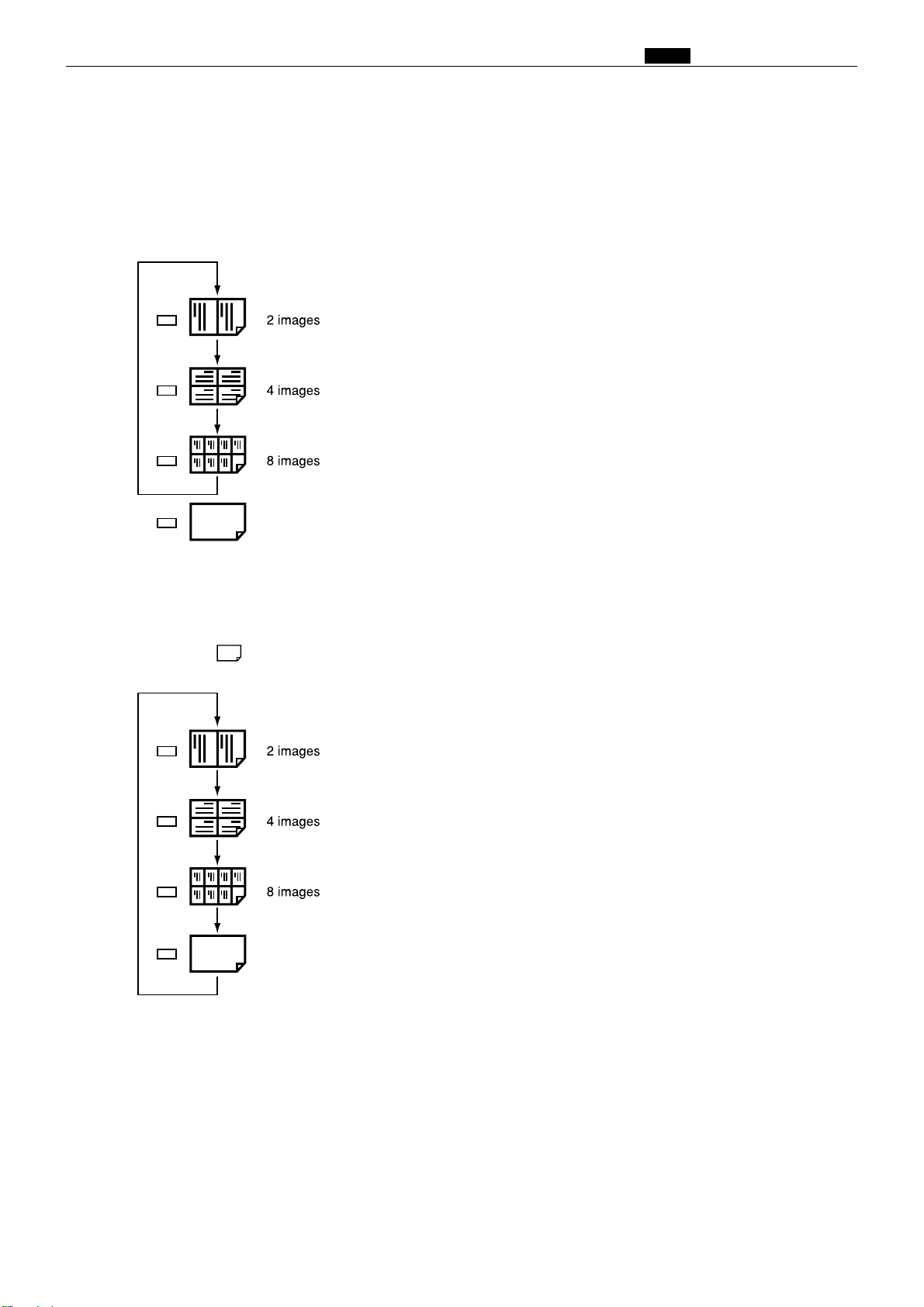
<<S type models>>
In the normal state (when the ADF is not connected) the mode is switched by pressing the
multiple printing selection key as follows.
Chap.1 . Operation Procedures
Every time the key is pressed, the mode is switched
and the relevant multiple printing indicator lamp
lights up.
• Each press of the multiple printing selection key makes
a different multiple printing indicator light up, in
sequence. To set the number of images, press the key
until the indicator for the desired number of images is
lit.
2in1
When the ADF is connected, the multiple printing selection key can also be used to select
the 2 in 1 Layout Mode, as shown below. To activate the 2 in 1 Layout Mode, press the key
until the " " icon is lit.
2in1
2in1
37
Page 37

Chap.1 ⁄0 Error Messages and Corrective Action
⁄0Error Messages and Corrective Action
1. Error messages
Error messages are displayed as text illustrations.
Message
CHANGE INK
CHANGE MASTER
CHANGE MASTER
EJECTION CORE
ADD PAPER
NO DRUM
DRUM CHANGE
A3<=>A4
Cause and corrective action
There is no ink. Replace the old ink pack with a new one.
There is no master. Replace the master roll with a new one.
The master ejection core is full. Replace the core with a new
one.
There is no paper in the feed tray. Load the feed tray with
printing paper.
There is no drum. Install a drum in the machine.
The installed drum is not the specified drum. Install the correct drum for this machine.
For DP-43E/S
See page
41
43
46
48
51
51
FRONT COVER OPEN
TOP COVER OPEN
PAPER JAM ON THE FEEDER SIDE
PAPER JAM ON THE EJECTION SIDE
PLATE EJECTION
ERROR
MASTER SETTING ERROR
ADF PAPER JAM
The front cover is open. Close the front cover.
The scanner unit is open. Close the scanner unit.
A paper jam has occurred in the feeder side. Inspect the feeder
side, and remove the jammed paper.
A paper jam has occurred on the ejection side. Inspect the
ejection side and remove the jammed paper.
There is an old master on the drum. Remove all the masters
from the drum.
There is an error during master setting. Open the top cover
and remove the master that is left in the plate feeder.
The document is jammed on the ADF. Remove the jammed
document in accordance with the ADF instruction manual.
4
4
53
54
55,57
59
ADF
Instruction
manual
13
38
Page 38

Chap.1 ⁄0 Error Messages and Corrective Action
C
T
Message
PLEASE WAIT
PLEASE INSERT CARD
RE-INSERT CARD
NOW READING CARD PLEASE WAIT
CANNOT USE THIS CARD
MAXIMIZING CARD
Cause and corrective action
The printer is not ready. Please wait with the power ON.
If the message remains after a few minutes, turn the power
OFF and ON again. If the message still remains after a few
minutes, turn the power OFF and contact your service person.
Insert the key card into the key card counter.
Please insert card.
Cannot read key card. Please reinsert the card.
Key card reading is in progress. Please wait.
You have inserted an unusable card. Check the card for dirt
and scratches, then reinsert the card.
Insert the highest-numbered of the cards that are to be used.
See page
4
62,78
62,78
62,78
62,78
62,77
CARD IS WRITE PROTECTED
CANNOT PRINT
PRINTING
You inserted suspended card. Use a different card or cancel
the card's suspension.
Cannot print.
This message is displayed if you press (PRINT) or
(TEST PRINT) keys without making a plate immediately
after a master setting error or master ejection error, or when
the confidential safeguard function is ON.
Printing is not complete. Either press (PRINT) key to
resume printing or press (CLEAR) key to clear the
counter.
E type : 65
S type : 71
4
4
39
Page 39

Chap.1 ⁄0 Error Messages and Corrective Action
Message
[C301A]
SORTER JAM1
[C302]
SORTER JAM3
[C303B]
SORTER JAM2
[C304]
SORTER DOOR OPEN
[C305]
STAPLER DOOR OPEN
[C306A]
NO STAPLES
Cause and corrective action
A paper jam has occurred in the paper path of sorter A.
Remove the jammed paper.
For details, see the Sorter Instruction Manual.
A paper jam has occurred in the sorter bridge. Remove the
jammed paper.
For details, see the Sorter Instruction Manual.
A paper jam has occurred in the paper path of sorter B.
Remove the jammed paper.
For details, see the Sorter Instruction Manual.
The sorter door is open. Close the sorter door.
For details, see the Sorter Instruction Manual.
The stapler door is open. Close the stapler door.
For details, see the Sorter Instruction Manual.
The stapler of sorter A is out of staples. Load staples.
For details, see the Sorter Instruction Manual.
See page
Sorter
Instruction
Manual
Sorter
Instruction
Manual
Sorter
Instruction
Manual
Sorter
Instruction
Manual
Sorter
Instruction
Manual
Sorter
Instruction
Manual
[C307]
NO STAPLES2
[C306A]
STAPLES JAM
[C307B]
STAPLES JAM2
[EXXX]
CALL THE SERVICE PERSON
The stapler of sorter B is out of staples. Load staples.
For details, see the Sorter Instruction Manual.
The staplers have jammed in sorter A. Remove the jammed
staples.
For details, see the Sorter Instruction Manual.
The staplers have jammed in sorter B. Remove the jammed
staples.
For details, see the Sorter Instruction Manual.
Note error code (EXXX).
Turn the power OFF and back ON again.
If the machine does not operate normally, call the service
person and describe the error code and conditions that led to
the situation as clearly as possible.
Sorter
Instruction
Manual
Sorter
Instruction
Manual
Sorter
Instruction
Manual
283
40
Page 40

2. Corrective action
(1) Replacing the Ink Pack
IMPORTANT
•Only use ink packs designed for this machine.
○○○○○○○○○○○○○○○○○○○○○○○○○○○○○○○○
Chap.1 ⁄0 Error Messages and Corrective Action
Open the front cover.
○○○○○○○○○○○○○○○○○○○○○○○○○○○○○○○○
Grasp the lever and pull it toward you.
Front cover
○○○○○○○○○○○○○○○○○○○○○○○○○○○○○○○○
Lift out the empty ink pack.
○○○○○○○○○○○○○○○○○○○○○○○○○○○○○○○○
Remove the cap from a new ink pack.
IMPORTANT
•Do not leave an ink pack uncapped for longer
than necessary.
○○○○○○○○○○○○○○○○○○○○○○○○○○○○○○○○○○○○○○○○○○○○○○○○○○○○○○○○○○○
41
Page 41

Chap.1 ⁄0 Error Messages and Corrective Action
○○○○○○○○○○○○○○○○○○○○○○○○○○○○○○○○
Insert the ink pack so that the groove on the lip
fits onto the “U” groove of the holder.
○○○○○○○○○○○○○○○○○○○○○○○○○○○○○○○○
Push the ink pack in to the set line on the ink
pack.
Set line
Set line
○○○○○○○○○○○○○○○○○○○○○○○○○○○○○○○○
Press the back of the holder in with the palm of
your hand.
○○○○○○○○○○○○○○○○○○○○○○○○○○○○○○○○
Close the front cover.
Front cover
○○○○○○○○○○○○○○○○○○○○○○○○○○○○○○○○○○○○○○○○○○○○○○○○○○○○○○○○○○○
42
Page 42
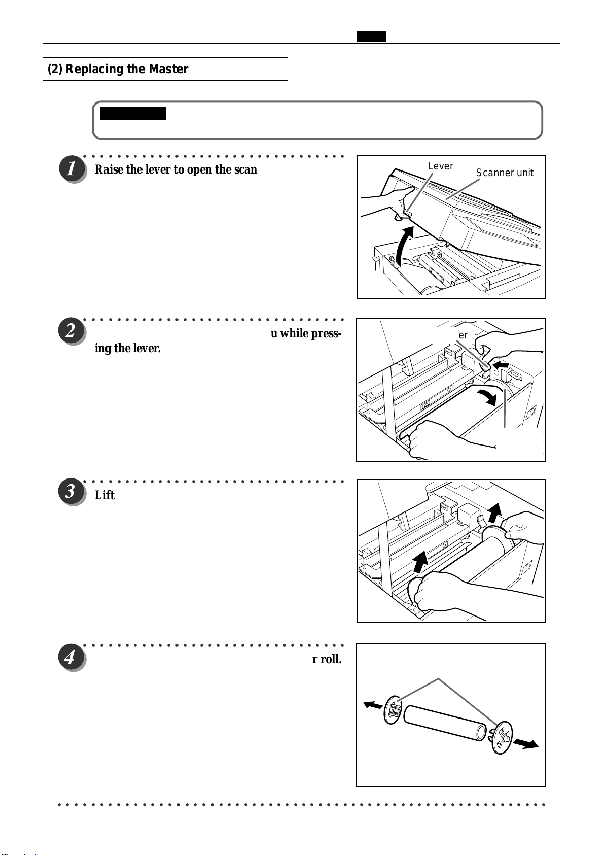
(2) Replacing the Master Roll
IMPORTANT
•Only use a master roll designed for use in this machine.
○○○○○○○○○○○○○○○○○○○○○○○○○○○○○○○○
Raise the lever to open the scanner unit.
○○○○○○○○○○○○○○○○○○○○○○○○○○○○○○○○
Chap.1 ⁄0 Error Messages and Corrective Action
Lever
Scanner unit
Turn the master holder toward you while pressing the lever.
○○○○○○○○○○○○○○○○○○○○○○○○○○○○○○○○
Lift out the master roll.
Lever
Master
Holder
○○○○○○○○○○○○○○○○○○○○○○○○○○○○○○○○
Remove the master holder from the master roll.
Holder
○○○○○○○○○○○○○○○○○○○○○○○○○○○○○○○○○○○○○○○○○○○○○○○○○○○○○○○○○○○
43
Page 43
Chap.1 ⁄0 Error Messages and Corrective Action
Green line
○○○○○○○○○○○○○○○○○○○○○○○○○○○○○○○○○○○○○○○○○○○○○○○○○○○○○○○○
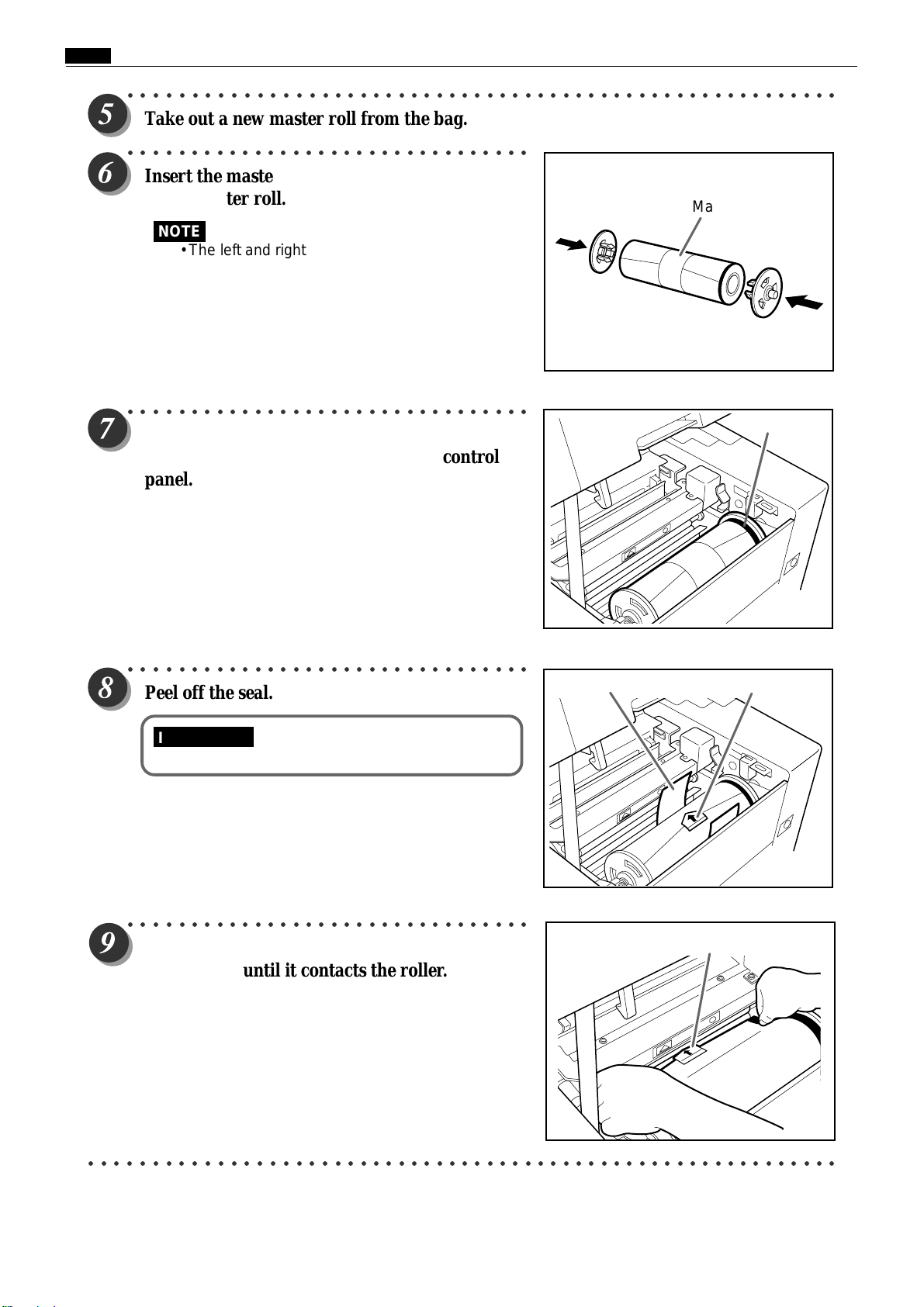
Take out a new master roll from the bag.
○○○○○○○○○○○○○○○○○○○○○○○○○○○○○○○○
Insert the master holder deeply into both ends
of the master roll.
NOTE
• The left and right holders are identical.
○○○○○○○○○○○○○○○○○○○○○○○○○○○○○○○○
Insert the master roll into the machine so that
the green line on the roll is facing the control
panel.
Master roll
○○○○○○○○○○○○○○○○○○○○○○○○○○○○○○○○
Peel off the seal.
IMPORTANT
•Do not peel off the yellow label.
○○○○○○○○○○○○○○○○○○○○○○○○○○○○○○○○
Pull out the master and insert the arrow on the
yellow label until it contacts the roller.
Yellow labelSeal
Yellow label
○○○○○○○○○○○○○○○○○○○○○○○○○○○○○○○○○○○○○○○○○○○○○○○○○○○○○○○○○○○
44
Page 44

○○○○○○○○○○○○○○○○○○○○○○○○○○○○○○○○
Press the master set switch.
The master is pulled in and automatically cut.
IMPORTANT
• If the master is not pulled in, press the yellow
label lightly toward the back.
• If the master is not installed correctly, it will
not be cut. Remove the master and reinstall it.
• If the master is wrinkled, press the lever in
step 2 two or three times while pressing and
holding the master set switch.
• When there are no more wrinkles in the
master, release your finger from the master
set switch.
○○○○○○○○○○○○○○○○○○○○○○○○○○○○○○○○
Remove the trimmed piece of the master.
IMPORTANT
• Do not forget to remove the cut end of the
master. Leaving cut master scraps in the
machine may result in machine trouble.
Chap.1 ⁄0 Error Messages and Corrective Action
Master set switch
○○○○○○○○○○○○○○○○○○○○○○○○○○○○○○○○
Gently close the scanner unit and press it down
until it locks.
WARNING
• Do not remove the cover with Warning
Label 1.
• You may be injured by the movable cutter
inside the machine.
○○○○○○○○○○○○○○○○○○○○○○○○○○○○○○○○○○○○○○○○○○○○○○○○○○○○○○○○○○○
45
Page 45

Chap.1 ⁄0 Error Messages and Corrective Action
(3) Replacing the Master Ejection Core
IMPORTANT
• Use only a master ejection core designed for use in this machine.
○○○○○○○○○○○○○○○○○○○○○○○○○○○○○○○○
Press the lever to open the master ejection box.
○○○○○○○○○○○○○○○○○○○○○○○○○○○○○○○○
Open the master ejection box until it stops.
○○○○○○○○○○○○○○○○○○○○○○○○○○○○○○○○
Open the cover while pressing and holding the
release lever.
○○○○○○○○○○○○○○○○○○○○○○○○○○○○○○○○
Holding the edges of the master ejection core,
pull out the core and discard it.
IMPORTANT
• Ink adheres to the master ejection core. Take
care to prevent ink from getting onto your
clothing.
○○○○○○○○○○○○○○○○○○○○○○○○○○○○○○○○○○○○○○○○○○○○○○○○○○○○○○○○○○○○○○○
46
Page 46

Chap.1 ⁄0 Error Messages and Corrective Action
○○○○○○○○○○○○○○○○○○○○○○○○○○○○○○○○○○○○○○○○○○○○○○○○○○○○○○○○
Insert a new master ejection core.
○○○○○○○○○○○○○○○○○○○○○○○○○○○○○○○○
Gently close the master ejection box cover,
pressing it until it locks.
○○○○○○○○○○○○○○○○○○○○○○○○○○○○○○○○
Close the master ejection box, pressing it until it
locks.
○○○○○○○○○○○○○○○○○○○○○○○○○○○○○○○○○○○○○○○○○○○○○○○○○○○○○○○○○○○
47
Page 47

Chap.1 ⁄0 Error Messages and Corrective Action
(4) Supplying Paper
Supplying Paper
○○○○○○○○○○○○○○○○○○○○○○○○○○○○○○○○
Open the supplemental paper tray if it is closed.
○○○○○○○○○○○○○○○○○○○○○○○○○○○○○○○○
Paper guides
Raise the paper guide lock lever to manually
move the paper guides.
○○○○○○○○○○○○○○○○○○○○○○○○○○○○○○○○○○○○○○○○○○○○○○○○○○○○○○○○
Set the paper guides to the size of the paper to be used.
○○○○○○○○○○○○○○○○○○○○○○○○○○○○○○○○
Load a stack of aligned sheets between the
paper guides and press the stack lightly toward
the machine.
○○○○○○○○○○○○○○○○○○○○○○○○○○○○○○○○
Lower the paper guide lock lever to lock the
paper guides in place.
48
Page 48

Changing Paper Selection
○○○○○○○○○○○○○○○○○○○○○○○○○○○○○○○○
Press (STOP) key.
Printing stops.
Chap.1 ⁄0 Error Messages and Corrective Action
○○○○○○○○○○○○○○○○○○○○○○○○○○○○○○○○
Press the paper tray descend switch
continuously. Release the switch when the paper
tray is at the proper height.
The paper tray will stop.
.
IMPORTANT
• If the sheet is still in the paper feed roller, pull it
out and align it with the stack.
Paper tray descending switch
○○○○○○○○○○○○○○○○○○○○○○○○○○○○○○○○
Remove paper from the paper tray.
The paper tray will automatically descend.
49
Page 49

Chap.1 ⁄0 Error Messages and Corrective Action
○○○○○○○○○○○○○○○○○○○○○○○○○○○○○○○○○○○○○○○○○○○○○○○○○○○○○○○○
Load paper.
○○○○○○○○○○○○○○○○○○○○○○○○○○○○○○○○
a a
a See page 48
a a
T
Press (PRINT) key.
Printing resumes.
NOTE
•When you press (PLATEMAKING) key,
“PRINTING” is displayed on the LCD panel.
•When you press (STOP) key, printing stops.
If Paper Runs Out During Printing
○○○○○○○○○○○○○○○○○○○○○○○○○○○○○○○○○○○○○○○○○○○○○○○○○○○○○○○○
If paper runs out during printing, printing stops and the paper tray is Lowered
automatically.
○○○○○○○○○○○○○○○○○○○○○○○○○○○○○○○○○○○○○○○○○○○○○○○○○○○○○○○○
a a
a See page 48
a a
Adding Paper While Printing
○○○○○○○○○○○○○○○○○○○○○○○○○○○○○○○○
Press (STOP) key.
Printing stops.
○○○○○○○○○○○○○○○○○○○○○○○○○○○○○○○○
Press the paper tray descend switch
continuously. Release the switch when the paper
tray reaches the proper height.
The paper tray will stop.
Paper tray descending switch
○○○○○○○○○○○○○○○○○○○○○○○○○○○○○○○○○○○○○○○○○○○○○○○○○○○○○○○○
50
Page 50

(5) Replacing the Drum Unit
○○○○○○○○○○○○○○○○○○○○○○○○○○○○○○○○
Press and hold the JOG switch until the drum
comes to a stop with a beep.
WARNING
•Do not touch the drum or rollers when you
operate the JOG switch.
•Do not put your hands or fingers inside the
machine while it is operating. Your hands
may be pulled in or nipped.
○○○○○○○○○○○○○○○○○○○○○○○○○○○○○○○○
Open the front cover toward you.
Chap.1 ⁄0 Error Messages and Corrective Action
JOG switch
(Drum rotator switch)
Front cover
○○○○○○○○○○○○○○○○○○○○○○○○○○○○○○○○
Lift the drum securing lever toward you and,
holding it there, then pull out the drum handle
straight toward you until it stops.
○○○○○○○○○○○○○○○○○○○○○○○○○○○○○○○○
Hold the handle on the far end of the drum, and
lift the front end of the drum slightly to pull the
drum toward you.
IMPORTANT
•Do not touch the drum surface. Ink may
transfer to your clothes.
•Hold the drum level and place it on a flat,
solid surface.
LeverDrum handle
Handle far end of
drum
○○○○○○○○○○○○○○○○○○○○○○○○○○○○○○○○○○○○○○○○○○○○○○○○○○○○○○○○○○○
51
Page 51

Chap.1 ⁄0 Error Messages and Corrective Action
Installing the Drum Unit
○○○○○○○○○○○○○○○○○○○○○○○○○○○○○○○○
Hold the drum level and place the drum guide
roller onto the rail in the machine.
○○○○○○○○○○○○○○○○○○○○○○○○○○○○○○○○
Release the handle at the far end of the drum
and press the drum in about 10cm while lifting
up the front end slightly.
Roller
Rail
○○○○○○○○○○○○○○○○○○○○○○○○○○○○○○○○○○○○○○○○○○○○○○○○○○○○○○○○
Hold the drum level and press it in gently until it comes to a stop.
○○○○○○○○○○○○○○○○○○○○○○○○○○○○○○○○
Lift the drum securing lever toward you while
Lever
pressing the drum in.
○○○○○○○○○○○○○○○○○○○○○○○○○○○○○○○○
Lower the lever.
Lever
○○○○○○○○○○○○○○○○○○○○○○○○○○○○○○○○○○○○○○○○○○○○○○○○○○○○○○○○
Close the front cover.
○○○○○○○○○○○○○○○○○○○○○○○○○○○○○○○○○○○○○○○○○○○○○○○○○○○○○○○○○○○
52
Page 52

(6) Paper Jam (Feeder Side)
If the message "PAPER JAM ON THE FEEDER SIDE" is
indicated in the error display panel, check the feeder side and
remove the jammed paper by following the procedure below.
Chap.1 ⁄0 Error Messages and Corrective Action
PAPER JAM ON THE FEEDER SIDE
○○○○○○○○○○○○○○○○○○○○○○○○○○○○○○○○
Press the paper tray descending switch to lower
the paper tray slightly.
The paper tray is lowered for the time that the
switch is pressed.
○○○○○○○○○○○○○○○○○○○○○○○○○○○○○○○○
Pull out the jammed paper as shown in the
diagram.
Paper tray descending switch
○○○○○○○○○○○○○○○○○○○○○○○○○○○○○○○○
Press and hold the JOG switch until the drum
comes to a stop with a beep.
WARNING
•Do not touch the drum or rollers when you
operate the JOG switch.
•Do not put your hands or fingers inside the
machine while it is operating. Your hands
may be pulled in or nipped.
○○○○○○○○○○○○○○○○○○○○○○○○○○○○○○○○○○○○○○○○○○○○○○○○○○○○○○○○○○○
JOG switch
(Drum rotator switch)
53
Page 53

Chap.1 ⁄0 Error Messages and Corrective Action
(7) Paper Jam (Ejection Side)
If the message "PAPER JAM ON THE EJECTION SIDE" is
indicated in the error display panel, check the ejection side and
remove the jammed paper by following the procedure below.
○○○○○○○○○○○○○○○○○○○○○○○○○○○○○○○○
Press the lever to open the master ejection box.
PAPER JAM ON THE EJECTION SIDE
○○○○○○○○○○○○○○○○○○○○○○○○○○○○○○○○
Open the master ejection box until it stops.
○○○○○○○○○○○○○○○○○○○○○○○○○○○○○○○○
Remove the jammed paper.
Press the JOG switch to eject the partially printed paper.
WARNING
•Do not touch the drum or rollers when you
operate the JOG switch.
•Do not put your hands or fingers inside the
machine while it is operating. Your hands
may be pulled in or nipped.
JOG switch
(Drum rotator switch)
○○○○○○○○○○○○○○○○○○○○○○○○○○○○○○○○○○○○○○○○○○○○○○○○○○○○○○○○
Close the master ejection box, pressing it until it
locks.
○○○○○○○○○○○○○○○○○○○○○○○○○○○○○○○○○○○○○○○○○○○○○○○○○○○○○○○○○○○
54
Page 54
Paper Adhering to Drum
○○○○○○○○○○○○○○○○○○○○○○○○○○○○○○○○
Press the lever to open the master ejection box.
○○○○○○○○○○○○○○○○○○○○○○○○○○○○○○○○
Open the master ejection box until it stops.
Chap.1 ⁄0 Error Messages and Corrective Action
○○○○○○○○○○○○○○○○○○○○○○○○○○○○○○○○
Press the JOG switch to find the edge of the
paper, then stop the drum at the position shown
in the diagram.
WARNING
•Do not touch the drum or rollers when you
operate the JOG switch.
•Do not put your hands inside the machine
while it is operating. Your hands may be
pulled in or nipped.
○○○○○○○○○○○○○○○○○○○○○○○○○○○○○○○○
Peel off the edge of the paper from the drum.
Paper edge
○○○○○○○○○○○○○○○○○○○○○○○○○○○○○○○○○○○○○○○○○○○○○○○○○○○○○○○○○○○
55
Page 55

Chap.1 ⁄0 Error Messages and Corrective Action
J
○○○○○○○○○○○○○○○○○○○○○○○○○○○○○○○○
Pull the paper toward the ejection side while
pressing the JOG switch to peel the paper off.
IMPORTANT
•Make sure that the peeled paper does not
stick to your clothing.
○○○○○○○○○○○○○○○○○○○○○○○○○○○○○○○○
Hold the JOG switch down until the drum
comes to a stop with a beep.
OG switch
(Drum rotator switch)
JOG switch
(Drum rotator switch)
○○○○○○○○○○○○○○○○○○○○○○○○○○○○○○○○
Close the master ejection box, pressing it until it
locks.
JOG switch
(Drum rotator switch)
○○○○○○○○○○○○○○○○○○○○○○○○○○○○○○○○○○○○○○○○○○○○○○○○○○○○○○○○
Make another plate.
○○○○○○○○○○○○○○○○○○○○○○○○○○○○○○○○○○○○○○○○○○○○○○○○○○○○○○○○○○○
56
Page 56

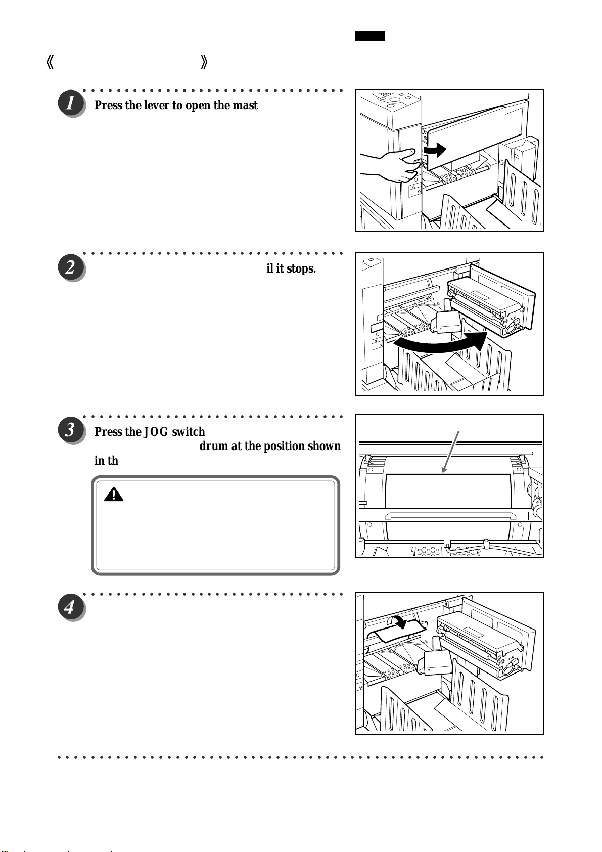
(8) Master is Not Ejected
○○○○○○○○○○○○○○○○○○○○○○○○○○○○○○○○
Press the lever to open the master ejection box.
○○○○○○○○○○○○○○○○○○○○○○○○○○○○○○○○
Open the master ejection box until it stops.
Chap.1 ⁄0 Error Messages and Corrective Action
○○○○○○○○○○○○○○○○○○○○○○○○○○○○○○○○
Press the JOG switch to find the edge of the
paper, then stop the drum at the position shown
in the diagram.
WARNING
•Do not touch the drum or rollers when you
operate the JOG switch.
•Do not put your hands inside the machine
while it is operating. Your hands may be
pulled in or nipped.
○○○○○○○○○○○○○○○○○○○○○○○○○○○○○○○○
Lift the lever toward you.
The master clump opens and the edge of the master will be
released from the clump. If the master is stuck, release it
manually.
Master clump
Master clamp
Master
Lever
○○○○○○○○○○○○○○○○○○○○○○○○○○○○○○○○○○○○○○○○○○○○○○○○○○○○○○○○○○○
57
Page 57

Chap.1 ⁄0 Error Messages and Corrective Action
○○○○○○○○○○○○○○○○○○○○○○○○○○○○○○○○○○○○○○○○○○○○○○○○○○○○○○○○
Return the lever.
○○○○○○○○○○○○○○○○○○○○○○○○○○○○○○○○
Pull the front end of the master toward you and
press the JOG switch intermittently.
Hold the switch down until the master peels off.
IMPORTANT
•Discard the old master, making sure that it
does not touch your clothing.
○○○○○○○○○○○○○○○○○○○○○○○○○○○○○○○○○○○○○○○○○○○○○○○○○○○○○○○○
Hold the JOG switch down until the drum comes to a stop with a beep.
○○○○○○○○○○○○○○○○○○○○○○○○○○○○○○○○
Close the master ejection box, pressing it until it
locks.
JOG switch
(Drum rotator switch)
JOG switch
(Drum rotator switch)
○○○○○○○○○○○○○○○○○○○○○○○○○○○○○○○○
Press (STOP) key.
The message is deleted.
○○○○○○○○○○○○○○○○○○○○○○○○○○○○○○○○○○○○○○○○○○○○○○○○○○○○○○○○
Make another plate.
○○○○○○○○○○○○○○○○○○○○○○○○○○○○○○○○○○○○○○○○○○○○○○○○○○○○○○○○○○○
58
Page 58
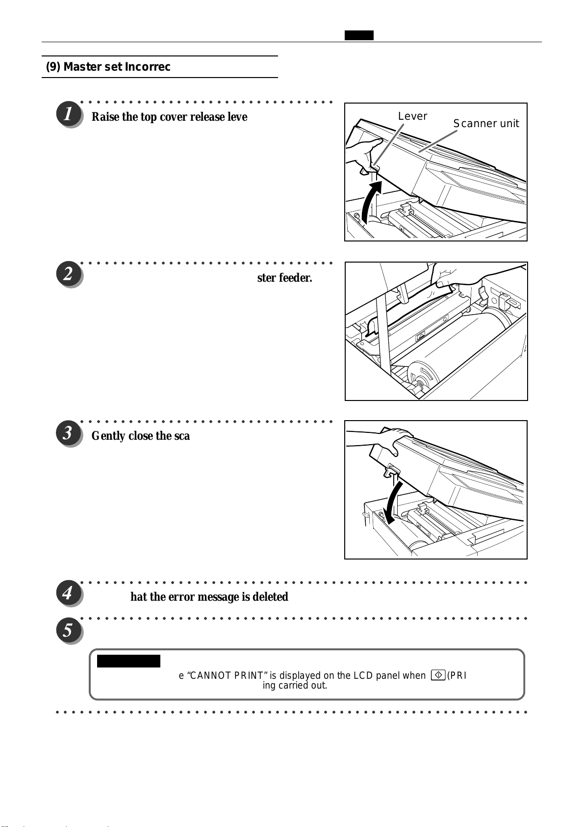
(9) Master set Incorrectly
○○○○○○○○○○○○○○○○○○○○○○○○○○○○○○○○
Chap.1 ⁄0 Error Messages and Corrective Action
Raise the top cover release lever to open the
scanner unit.
○○○○○○○○○○○○○○○○○○○○○○○○○○○○○○○○
Remove the master left in the master feeder.
Lever
Scanner unit
○○○○○○○○○○○○○○○○○○○○○○○○○○○○○○○○
Gently close the scanner unit and press it until
it locks.
○○○○○○○○○○○○○○○○○○○○○○○○○○○○○○○○○○○○○○○○○○○○○○○○○○○○○○○○
Check that the error message is deleted.
○○○○○○○○○○○○○○○○○○○○○○○○○○○○○○○○○○○○○○○○○○○○○○○○○○○○○○○○
Make a new plate and start printing.
IMPORTANT
•The message “CANNOT PRINT” is displayed on the LCD panel when (PRINT) key is
pressed without platemaking being carried out.
○○○○○○○○○○○○○○○○○○○○○○○○○○○○○○○○○○○○○○○○○○○○○○○○○○○○○○○○○○○
59
Page 59
Chap.1 ⁄0 Error Messages and Corrective Action
⁄1Option
1. DUPRINTER Option
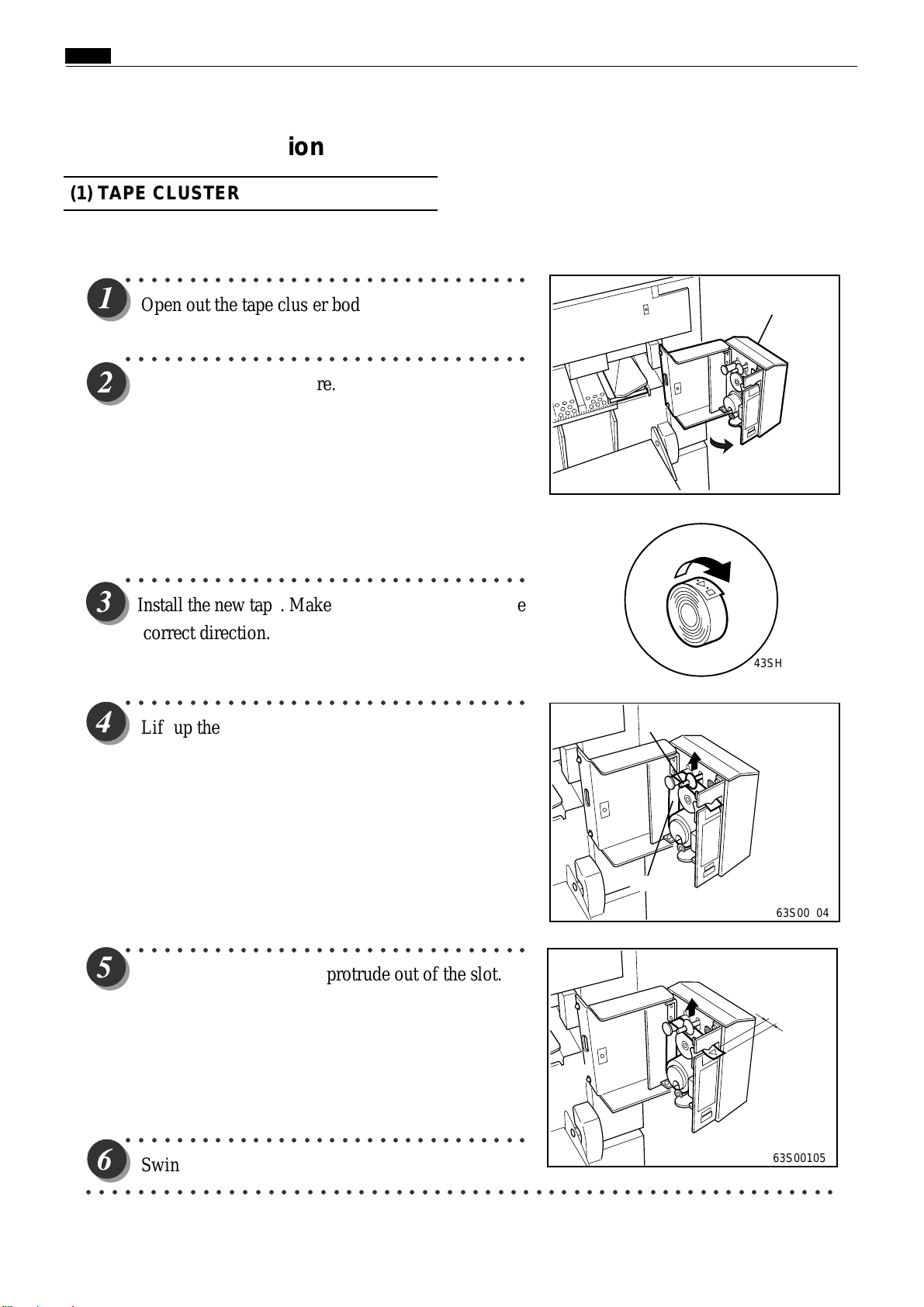
(1) TAPE CLUSTER
○○○○○○○○○○○○○○○○○○○○○○○○○○○○○○○○
Open out the tape cluster body.
○○○○○○○○○○○○○○○○○○○○○○○○○○○○○○○○
Remove the old tape core.
○○○○○○○○○○○○○○○○○○○○○○○○○○○○○○○○
Install the new tape. Make sure it will wind of f in the
correct direction.
○○○○○○○○○○○○○○○○○○○○○○○○○○○○○○○○
Lift up the lever and pass the tape through the slot.
Tape cluster body
63S00103
43SH0104
Lever
Tape
63S00104
○○○○○○○○○○○○○○○○○○○○○○○○○○○○○○○○
Make about 1cm of tape protrude out of the slot.
BB
1
B
BB
○○○○○○○○○○○○○○○○○○○○○○○○○○○○○○○○
Swing the tape cluster body back in.
○○○○○○○○○○○○○○○○○○○○○○○○○○○○○○○○○○○○○○○○○○○○○○○○○○○○○○○○○○○
60
63S00105
Page 60

(2) KEYCARD COUNTER 3
1. About keycard counter 3
<<
Features
There are the following types of keycard.
¡
Department cards (AA01-AA30)
Each cards is able to totalize the number of prints
and plates made on the DUPRINTER by a
particular department. One card is assigned to
each department, so up to 30 departments can be
handled.
*Extra cards (up to AA200) can optionally be provided, to
expand handling capacity to up to 200 departments.
¡
Control cards
The control cards come in a set of 3:
a CLEAR card, a RESTRICTION card, and a
TOTAL card.
*
The control cards should be kept by the printer
manager.
>>
Chap.1 ⁄0 Error Messages and Corrective Action
AA01
• CLEAR card (AA CLEAR)
For resetting to zero the print and plate counts of
individual department cards.
• RESTRICTION card (AA RESTRICTION)
For prohibiting or de-prohibiting use of individual
department cards.
Use this when department cards are lost, or other
applicable situations.
• TOTAL card (AA TOTAL)
For displaying the departments' print and plate counts on
the LC screen, for checking. The screen can display the
counts for 8(in S type models, 5) departments at a time.
IMPORTANT
When 2 DUPRINTERs equipped with KEYCARD
COUNTER 3 are used in tandem:
Use department cards AA01-AA30 with one
DUPRINTER, and a separate set of cards (BB01-BB30,
optionally supplied) with the other. Keep use of the cards
separate; do not use both AA and BB cards with one
machine.
¡CLEAR CARD
AA CLEAR
¡RESTRICT CARD
AA RESTRICTION
¡TOTAL CARD
AA TOTAL
BB01
61
Page 61

Chap.1 ⁄1 Option
DUPLICATORMESSAGE
PLEASEINSERT CARD
DUPLICATORMESSAGE
NOWREADINGCARD.PLEASEWAIT
About keycards
¡
Handling
• Do not bend the cards. Keep the cards clean. Keep the cards away from all sources of magnetism.
¡
Inserting the cards
1.
"PLEASE INSERT CARD" will appear on the LC
display.
¡E type
Press the DUPRINTER's power switch to turn it on.
Insert the keycard into the DUPRINTER's keycard slot.
2.
*Be sure to insert the card the right way around.
When the card has been inserted, "NOW READING
CARD. PLEASE WAIT" will appear briefly, then be
replaced by the base screen for the type of card
inserted.
¡S type
¡E type
¡S type
*If the message "RE-INSERT CARD" appears on the LCD panel, insert the card once more.
IMPORTANT
While the "PLEASE WAIT" message is displayed on the LCD panel, do NOT:
• turn off the power to the DUPRINTER
• press the DUPRINTER's ALL CLEAR key
• remove the keycard from its slot.
62
Page 62
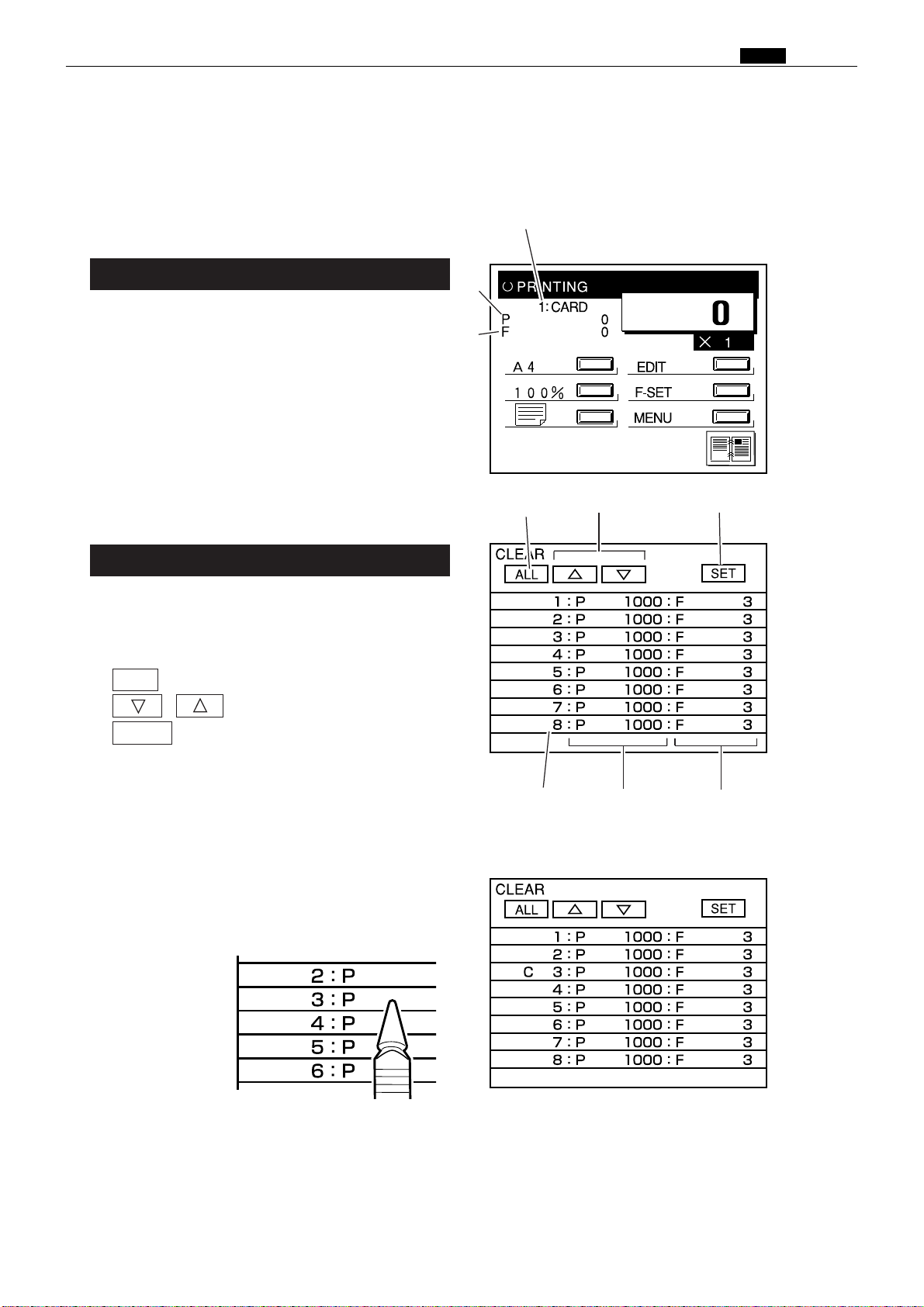
2. Using keycards (for E type models)
In the E type models, input is by pen. Use only
1
the input pen supplied.
1Apply the pen to the LC screen gently. Do
not press hard on the screen.
q
Chap.1 ⁄1 Option
Department card (AA01-AA30)
Insert a department card into the DUPRINTER's
1.
keycard slot. The base screen will appear on the LC
panel. The DUPRINTER is now ready for use.
qKeycard No.
("1" in the illustration means card AA01)
wPrint count
ePlate count
CLEAR card (AA CLEAR)
Insert the CLEAR card. "NOW READING
1.
CARD. PLEASE WAIT" will appear on the LC
panel, then be replaced by the base screen.
q
ALL key
w
, keys
w
e
q
w
e
e
SET key
r
Department card Nos.
t
Print count
y
Plate count
Press the number of the department card
2.
whose print and plate counts are to be cleared.
"C" will appear to the left of the number
pressed.
a
r
t
y
63
Page 63
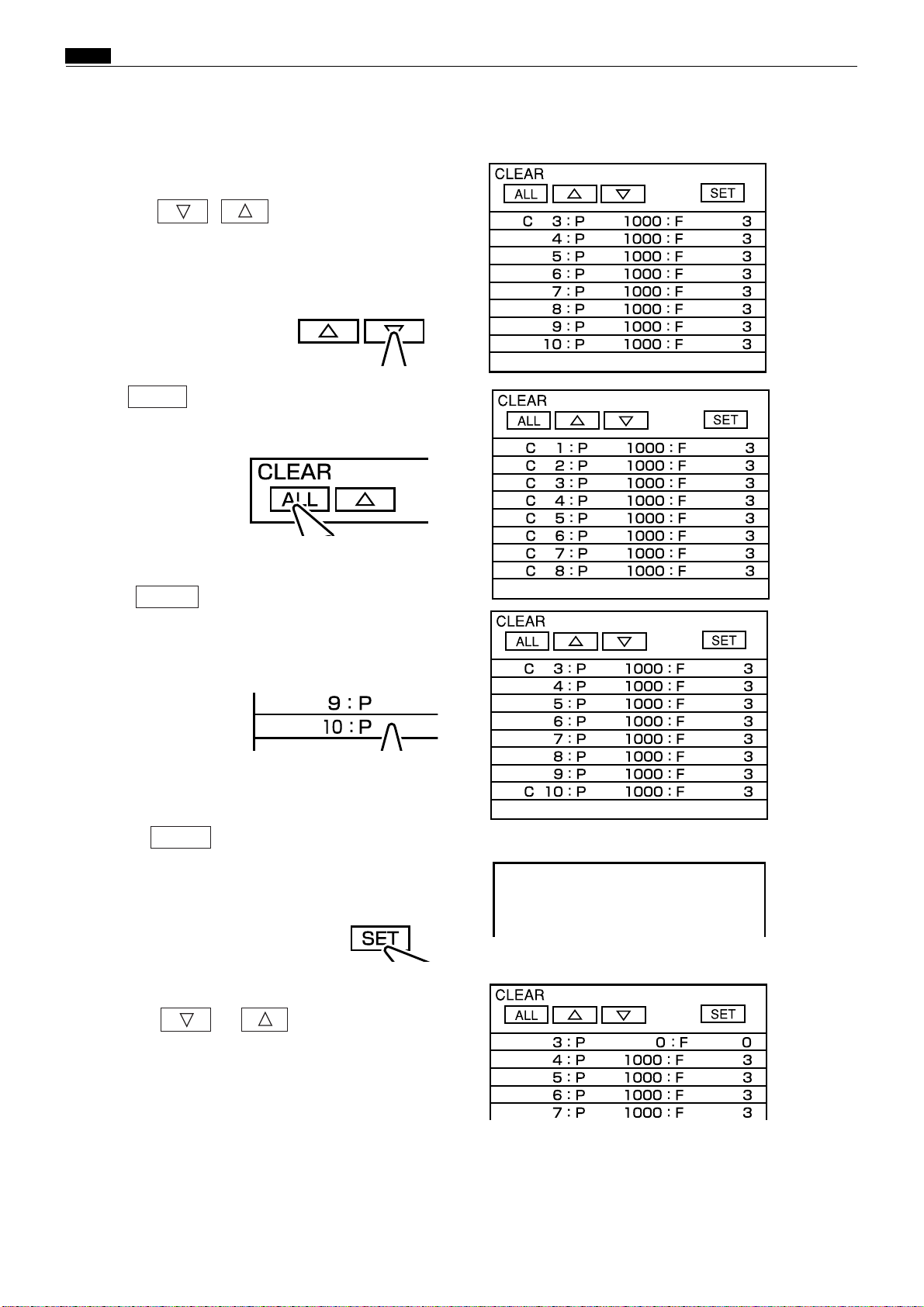
Chap.1 ⁄1 Option
5
DUPLICATORMESSAGE
PLEASEWAIT
S
To select department card No. 9 or
higher:
Press the , key
repeatedlyuntil the desired card number is
reached.
Each press of the key scrolls the display down 1
line.
S
To select all the department cards:
Press ALL .
"C" will appear to the left of all of the
department card numbers.
Now go to step
.
4
a
a
S
To delete the Cs
(deselect all the cards):
Press ALL again. All the Cs will disappear
from the LC screen.
If there is another card whose print and plate
3.
counts you want to clear, repeat the operation
in step
When selection of the card(s) whose print
4.
and plate counts are to be cleared is
complete,
press SET .
"PLEASE WAIT" will be appear briefly on the
screen. Then the display will return to the base
screen that was displayed in step
S
To check that the counts have been
to select it.
2
.
1
cleared:
Press the or key to display the
card number(s) that was selected, and check
that the print count (5) and plate count (6) are
zero.
a
a
a
Remove the keycard from its slot.
.
64
Page 64

Chap.1 ⁄1 Option
RESTRICTION card (AA RESTRICTION)
Insert the RESTRICTION card. "NOW
1.
READING CARD. PLEASE WAIT" will
appear on the LC panel, then be replaced by
the base screen.
q
ALL key
w
e
r
Department card Nos.
t
Print count
y
Plate count
Press the number of the department card
2.
whose use is to be prohibited. " " will
appear to the left of the number pressed.
, keys
SET key
a
q
r
w
t
e
y
S
To select department card No. 9 or
higher:
Press the or key repeatedly until
the desired card number is reached.
Each press of the key scrolls the display down 1
line.
S
To select all the department cards:
Press ALL .
" " will appear to the left of all the department
card numbers.
Now go to step
4
.
a
a
65
Page 65

Chap.1 ⁄1 Option
DUPLICATORMESSAGE
PLEASEWAIT
S
To delete the " " s (deselect all the
cards):
Press ALL again. All the ""s will
disappear from the LC screen.
If there is another card whose use you want
3.
to prohibit, repeat the operation in step
select it.
2
to
a
When selection of the card(s) whose use is to
4.
be prohibited is complete, press
"PLEASE WAIT" will be appear briefly on the
screen. Then the display will return to the base
screen that was displayed in step
S
To check that card use has been
SET
.
1
.
prohibited:
Press the or key to display the
card number(s) that was selected, and check
that the " " (indicating use prohibited) is
displayed to the left of the number(s).
Remove the keycard from its slot.
5.
a
a
66
Page 66

TOTAL card (AA TOTAL)
Insert the TOTAL card. "NOW READING
1.
CARD. PLEASE WAIT" will appear on the LC
panel, then be replaced by the screen on the
right.
If the number of the card whose counts you
2.
want to check is 9 or higher, press or
as many times as needed to display it.
• Maximum print count: 799999
• Maximum plate count: 7999
When the number of prints/plates made reaches
the maximum, the count restarts from zero.
Chap.1 ⁄1 Option
S
""
to the left of a card number
indicates that use of that card has
been prohibited.
67
Page 67

Chap.1 ⁄1 Option
2. Using keycards (for S type models)
Department cards (AA01-AA30)
Insert a department card into the
1.
DUPRINTER's keycard slot. The base screen
will appear on the LCD panel. The
DUPRINTER is now ready for use.
qKeycard No. ("1" in the illustration means card
AA01)
wPrint count
ePlate count
CLEAR card (AA CLEAR)
Insert the CLEAR card. "NOW READING
1.
CARD. PLEASE WAIT" will appear on the
LCD panel, then be replaced by the base
screen.
qCLEAR EACH: clears individual department
cards
wCLEAR ALL: clears all department cards
q
e
w
qw
To select individual department cards:
2.
Press the ZOOM key to select CLEAR EACH,
then press the AUTO ZOOM key to confirm.
The screen shown below will appear.
qDepartment card No.
wPrint count
ePlate count
ZOOM key
AUTO ZOOM key
a
a
q
68
w
e
Page 68

S
To select all the department cards:
Press the ZOOM key to select CLEAR ALL,
then press the AUTO ZOOM key to confirm.
A list of the department card numbers will
appear, with all the print w and plate e counts
reset to zero.
Chap.1 ⁄1 Option
a
a
a
Press the ZOOM key to select the card whose
3.
counts are to be cleared, then press the
AUTO ZOOM key to confirm. "C" will appear
to the left of the selected card number.
a
a
69
Page 69

Chap.1 ⁄1 Option
S
To select department card No. 6 or
higher
Press the ZOOM key repeatedly until the
desired card number is reached.
Each press of the key scrolls the display down 1
line.
S
To delete the C (deselect the card):
Select the card again, using the ZOOM key,
then press the AUTO ZOOM key to confirm.
:
a
If there is another card whose print and plate
4.
counts you want to clear, repeat the operation
in step
When selection of the card(s) whose print and
5.
plate counts are to be cleared is complete,
press the PRINT SIZE key.
"PLEASE WAIT" will be appear briefly on the
screen. Then the display will return to the base
screen that was displayed in step
to select it.
3
1
.
a
a
a
S
To check that the counts have been
cleared:
Select CLEAR EACH, then press the ZOOM key
to display the card number(s) that was selected,
and check that the print and plate counts are
zero.
Remove the keycard from its slot.
6.
a
70
Page 70

Chap.1 ⁄1 Option
RESTRICTION card (AA RESTRICTION)
Insert the RESTRICTION card. "NOW READING
1.
CARD. PLEASE WAIT" will appear on the LCD
panel, then be replaced by the base screen.
q
RESTRICT EACH: prohibits use of individual
department cards
w
RESTRICT ALL: prohibits use of all department
cards
e
CLEAR ALL RESTRICT: de-prohibits use of all
department cards
To select individual department cards:
2.
Press the ZOOM key to select RESTRICT EACH,
then press the AUTO ZOOM key to confirm.
The screen shown below will appear.
q
Department card No.
w
Print count
e
Plate count
a
q
ew
ZOOM key
AUTO ZOOM key
a
qw e
71
Page 71
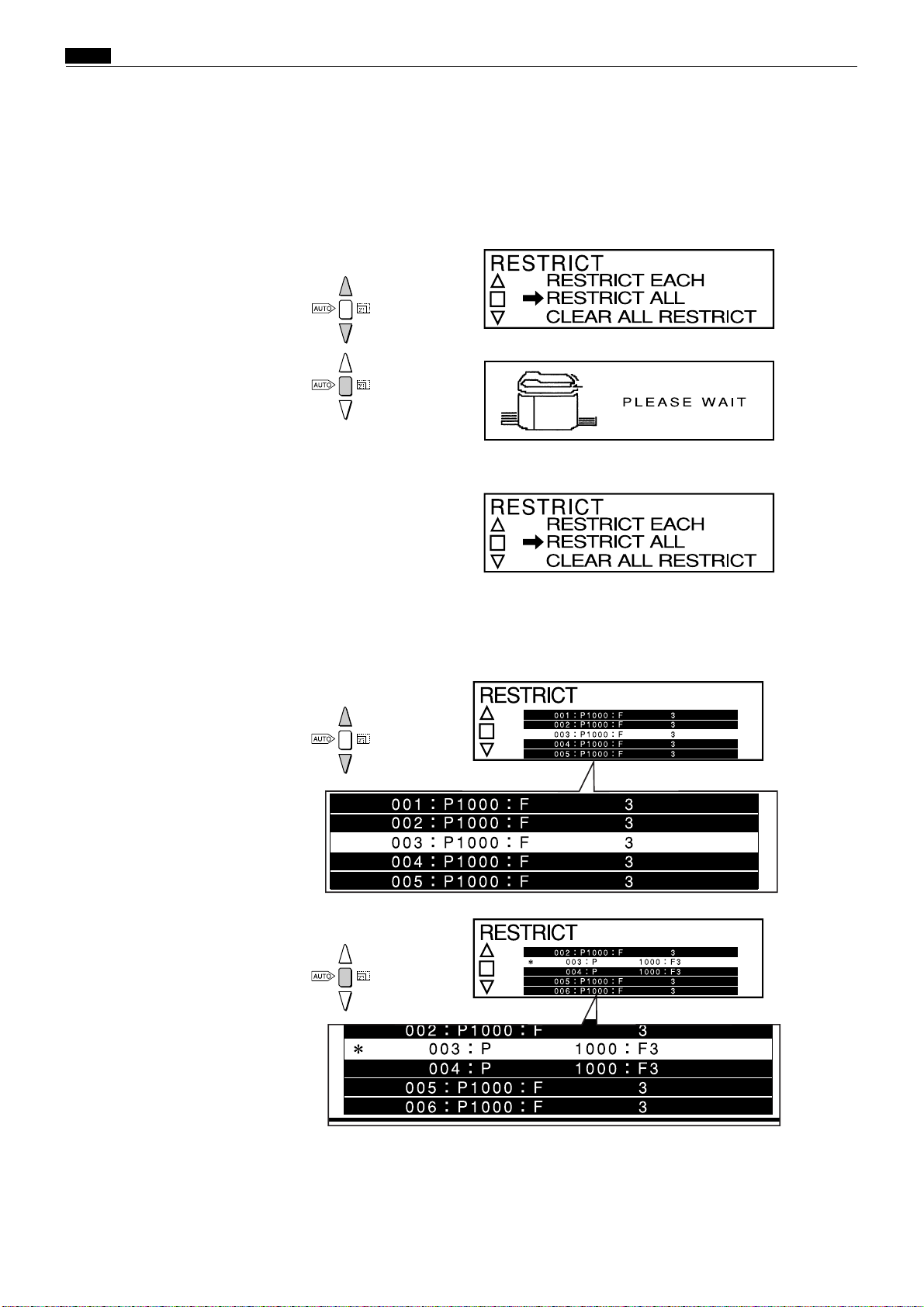
Chap.1 ⁄1 Option
S
To select all the department cards:
Press the ZOOM key to select RESTRICT ALL, then
press the AUTO ZOOM key to confirm.
A list of the department card numbers will appear,
with "1" to the left of all the numbers.
a
a
a
Press the ZOOM key to select the card whose use
3.
is to be prohibited, then press the AUTO ZOOM
key to confirm.
"1 " will appear to the left of the selected card
a
a
72
Page 72

S
To select department card No. 6 or
higher:
Press the ZOOM key repeatedly until the desired card
number is reached.
Each press of the key scrolls the display down 1 line.
a
S
To delete the
Select the card again, using the ZOOM key, then press
the AUTO ZOOM key to confirm.
(deselect the card):
"1"
Chap.1 ⁄1 Option
If there is another card whose use you want to
4.
prohibit, repeat the operation in step
When selection of the card(s) whose use is to
5.
be prohibited is complete, press the PRINT
SIZE key.
"PLEASE WAIT" will be appear briefly on the
screen. Then the display will return to the base
screen that was displayed in step
to select it.
3
.
2
a
a
a
a
73
Page 73

Chap.1 ⁄1 Option
S
To check that the counts have been
cleared:
Select RESTRICT EACH, then press the ZOOM key to
display the card number(s) that was selected, and
check that "1" (indicating use prohibited) is displayed
to the left of the number(s).
S
To delete all the
cards):
Press the ZOOM key to select CLEAR ALL
RESTRICT, then press the AUTO ZOOM key to
confirm.
"PLEASE WAIT" will be appear briefly on the screen.
Then the display will return to the base screen that
was displayed in step
2
s (deselect all the
"1"
.
a
Remove the keycard from its slot.
6.
a
a
74
Page 74
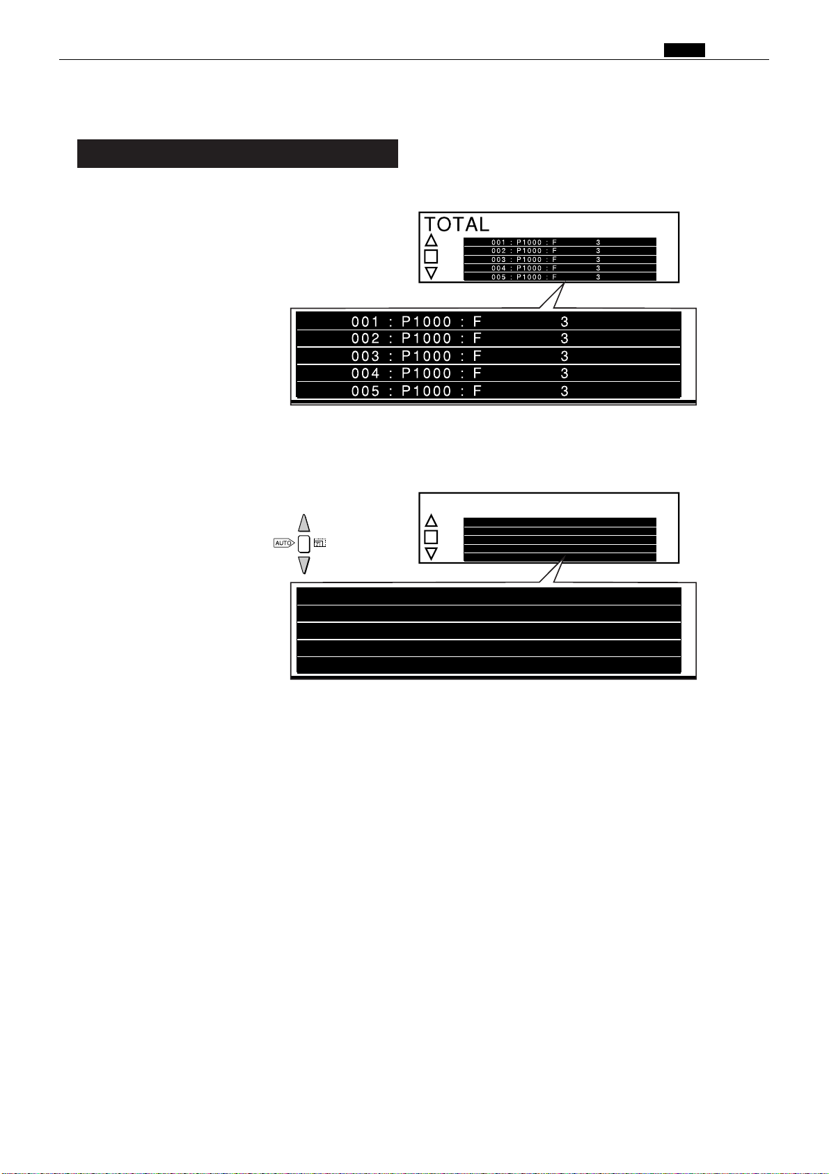
TOTAL
001 : P1000 : F 3
002 : P1000 : F 3
003 : P1000 : F 3
004 : P1000 : F 3
1
005 : P1000 : F 3
001 : P1000 : F 3
002 : P1000 : F 3
003 : P1000 : F 3
004 : P1000 : F 3
1
005 : P1000 : F 3
TOTAL card (AA TOTAL)
Insert the TOTAL card. "NOW READING
1.
CARD. PLEASE WAIT" will appear on the
LCD panel, then be replaced by the screen on
the right.
If the number of the card whose counts you
2.
want to check is 6 or higher, press the ZOOM
key as many times as needed to display it.
Chap.1 ⁄1 Option
a
• Maximum print count: 799999
• Maximum plate count: 7999
When the number of prints/plates made reaches
the maximum, the count restarts from zero.
S
"1" to the left of a card number
indicates that use of that card has
been prohibited.
75
Page 75
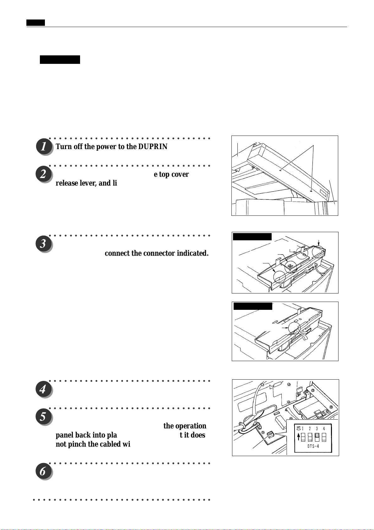
Chap.1 ⁄1 Option
3. Setting the maximum number of cards that can be used with the KEYCARD COUNTER 3
IMPORTANT
Observe the following when setting (increasing) the number of cards that can be used with the
KEYCARD COUNTER 3:
¡Perform the setting operation after installation of the DUPRINTER is complete.
¡Perform the setting operation after installation of the KEYCARD COUNTER 3 is complete.
¡Remove the DUPRINTER power cable's plug from the outlet before performing the setting operation.
¡Be sure to install the various screws in the correct places.
○○○○○○○○○○○○○○○○○○○○○○○○○○○○○○○○
Turn off the power to the DUPRINTER.
○○○○○○○○○○○○○○○○○○○○○○○○○○○○○○○○
Open the front cover, lift up the top cover
release lever, and lift up the top cover. Then
remove the two screws from the underside of
the operation panel.
* Retain the two operation panel mounting screws, as they
will be reused later.
○○○○○○○○○○○○○○○○○○○○○○○○○○○○○○○○
Slightly raise up the upper half of the operation
panel. Then disconnect the connector indicated.
E type : The 5 connectors shown below.
S type : The 1 connector shown below.
Scanner unit
E type models
2connector
1connector
S type models
Screws
Front
cover
1connector
1connector
○○○○○○○○○○○○○○○○○○○○○○○○○○○○○○○○
Set DIP SW 3 to ON.
○○○○○○○○○○○○○○○○○○○○○○○○○○○○○○○○
Reinsert the cabled wire connector that was
disconnected in step 3, and lower the operation
panel back into place, making sure that it does
not pinch the cabled wire.
○○○○○○○○○○○○○○○○○○○○○○○○○○○○○○○○
Turn on the power to the DUPRINTER.
○○○○○○○○○○○○○○○○○○○○○○○○○○○○○○○○○○○
1Connector
DIP SW
76
Page 76

○○○○○○○○○○○○○○○○○○○○○○○○○○○○○○○○
Insert a keycard into the DUPRINTER's key
card slot.
○○○○○○○○○○○○○○○○○○○○○○○○○○○○○○○○
The message MAXIMIZING CARD should
appear. When it does, remove the keycard.
○○○○○○○○○○○○○○○○○○○○○○○○○○○○○○○○
Insert the highest-numbered of the keycards to
be used.
Example: If 50 keycards numbered AA01 through AA50 are
to be used, insert the card bearing the number AA50.
Chap.1 ⁄1 Option
MAXIMIZING CARD
○○○○○○○○○○○○○○○○○○○○○○○○○○○○○○○○
Provided that no reading error occurs, the
number of the card inserted will be displayed,
and that number will be registered as the
maximum number of cards that can be used.
○○○○○○○○○○○○○○○○○○○○○○○○○○○○○○○○
Remove the card, and turn off the power to the
DUPRINTER.
○○○○○○○○○○○○○○○○○○○○○○○○○○○○○○○○
Repeat steps 2 and 3, then set DIP SW 3 (which
was set to ON in step 4) back to OFF.
○○○○○○○○○○○○○○○○○○○○○○○○○○○○○○○○
Reinsert the cabled wire connector that was
disconnected when you repeated step 3, and
lower the operation panel back into place,
making sure that it does not pinch the cabled
wire.
Card No.
DIP switch
○○○○○○○○○○○○○○○○○○○○○○○○○○○○○○○○
Turn on the power to the DUPRINTER, and
once more insert the highest-numbered card
(e.g. AA50), to check that the number of cards
that can be used has been increased to the new
setting.
○○○○○○○○○○○○○○○○○○○○○○○○○○○○○○○○○○○○○○○○○○○○○○○○○○○○○○○○○○○
77
Page 77

Chap.1 ⁄1 Option
4. Message displays
Message Meaning
¡"PLEASE INSERT CARD"
¡"NOW READING CARD PLEASE
¡"PLEASE WAIT"
WAIT"
•
No keycard has been inserted into the
DUPRINTER's keycard slot.
f
Insert a keycard into the slot
•
The DUPRINTER is reading the
CLEAR/RESTRICTION/TOTAL card.
•
When the CLEAR card is used: Clearing
(resetting) of print and plate counts is in
progress.
•
When the RESTRICTION card is used:
Prohibition of the use of a department
card(s) is being registered.
¡"RE-INSERT CARD"
¡"CARD IS WRITE-PROTECTED"
¡"CANNOT USE THIS CARD"
IMPORTANT
•
While the "PLEASE WAIT" message is
displayed on the LCD panel, do NOT:
•
turn off the power to the DUPRINTER
•
press the DUPRINTER's ALL CLEAR key
•
remove the keycard from its slot.
Reading of the card inserted has taken
more than 2 seconds to complete (timed from
moment of insertion), OR
•
the power to the DUPRINTER was turned on
with a card already inserted, OR
•
an error occurred in reading the card.
Remove the card, then re-insert it into the slot.
•
Use of the card inserted (department card,
AA***) has been prohibited.
•
The card inserted (department card) is of the
wrong series, OR
•
the card inserted is of the correct series, but
has a number higher than the applicable
maximum number of cards that can be used.
78
Page 78

5. Specifications
Main specifications
Name KEYCARD COUNTER 3
Power supply 5V DC (supplied from the DUPRINTER)
Power consumption 0.5W
Max. depts. handled 200
Max. counts per dept.
Card reading method Magnetic scan
Print count: 799,999
Plate count: 7,999
Chap.1 ⁄1 Option
79
Page 79
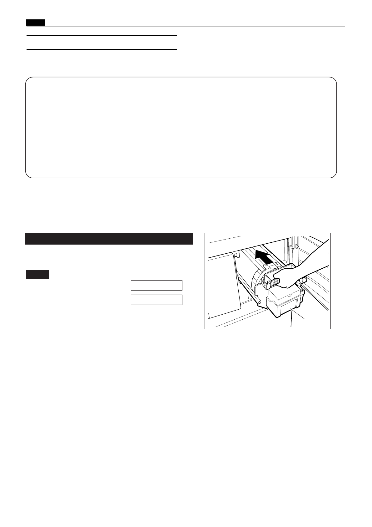
Chap.1 ⁄1 Option
(3) A4 DRUM (for DP-43E/S)
1. About A4drum
¡Features of the A4 drum:
•Simple to replace with a standard (A3) drum.
•Uses the roll master economically.
•Cost per sheet is lower than with the standard (A3) drum
¡About functions when the A4 drum is installed
When the A4 drum is installed, the following functions can not be used:
•Multiple image printing; "2inl" when the S1-ADF (option) is installed
• Book shadow eraser
• Online platemaking
2. Using A4drum
1.
Drum replacement
Open the front cover. Then remove the A3 (or A4) drum,
and install the A4 (or A3) drum.
Note
:
¡For drum removal method :
¡For drum Instruction method :
\See page 51
\See page 52
A4 drum
80
Page 80

EDIT
F-SET
MENU
PRINTING
1
×
A3
100%
PRINTING
MENU
6.DRUMSIZE
SPECIALFUNCTION
A4A3
SPECIALFUNCTION
6.DRUMSIZE
A4
A3
SPECIALFUNCTION
6.DRUMSIZE
A4
A3
PRINTING
MENU
2.
A4 drum setup (for DP-43E)
Chap.1 ⁄1 Option
• Basic screen
IMPORTANT
1.
Make sure that the basic screen is displayed.
2.
Press MENU.
3.
Press the " " special function icon.
4.
Press or repeatedly until the display
shown on the right is displayed.
:
In E type machines, input is by pen. For
input, be sure to use the input pen
provided among the accessories. Do not
apply undue pressure to the LCD pa
△
▽
nel.
5.
Press " A4". When pressed, it will change to " A4".
IMPORTANT
6.
Press the return icon.
7.
Press the return icon.
The basic screen will be displayed.
•
A3 drum setup
The procedure for setup of an A3 drum (after an A3
drum has been installed) is the same as that for setup
of an A4 drum above, except that " A3" must be
pressed instead of " A4" in step 5.
:
• If an A3 drum has been installed, setup of
an A4 drum can not be performed. In such
a case, first install an A4 drum, then start
again from step 1.
• If an A4 drum has been installed, setup of
an A3 drum can not be performed. In such
a case, first install an A3 drum, then start
again from step 1.
81
Page 81

Chap.1 ⁄1 Option
6. Drum size
A 3
A 4
6. Drum size
A 3
A 4
6. Drum size
A 4
6. Drum size
A 3
AUTO
AUTO
2.
A4 drum setup (for DP-43S)
1.
Make sure that the basic screen is displayed.
2.
Open the panel cover, and press the SPECIAL
FUNCTION key.
3.
Press the ZOOM key repeatedly until the
display shown on the right is displayed.
4.
Press the AUTO ZOOM key. The display
shown on the right will appear.
¡Basic screen
Panal cover
5.
Press the ZOOM key. "A4" will be highlighted
IMPORTANT :
• If an A3 drum has been installed, setup of
an A4 drum can not be performed. In such
a case, first install an A4 drum, then start
again from step 1.
• If an A4 drum has been installed, setup of
an A3 drum can not be performed. In such
a case, first install an A3 drum, then start
again from step 1.
6.
Press the AUTO ZOOM key. The display
shown on the right will appear, and the setting
shown in the display will be confirmed.
7.
Press the SPECIAL FUNCTION key.
The basic screen will reappear.
•
A3 drum setup
.
The procedure for setup of an A3 drum (after an A3
drum has been installed) is the same as that for setup
of an A4 drum above, except that "A3" must be
pressed instead of "A4" in step 5.
82
Page 82

3.
DRUM CHANGE
A3 A4
Placing the document / placing the paper
Note
:
¡For method for placing the document:
E type : See p.23 of the DP-43E/33E/ 31E Instruction
Manual.
S type : See p.24 of the DP-43S/33S /31S Instruction
Manual.
¡For method for selecting the paper size:
E type : See p.24 of the DP-43E/33E/ 31E Instruction
Manual.
S type : See p.25 of the DP-43S/33S /31S Instruction
Manual.
¡For method for placing the paper:
\See page 48
Chap.1 ⁄1 Option
¡
Placing the document when an A4 drum is use
A4
B5A5
Broken lines
indicate where
document is placed
when A3 drum is
used
A4R
Document
B5R
A5R
¡
When the error message shown
below is displayed:
If the drum setting is A4 but an A3 drum has
been installed, or if the drum setting is A3 but an
A4 drum has been installed, the display on the
right will appear when the PLATEMAKING
key is pressed.
Corrective action:
Press the STOP key. Then replace the
drum, and perform drum setup.
¡Display in E type machine
DUPLICATORMESSAGE
DRUMCHANGE
A3A4
¡Display in S type machine
83
Page 83

84
Chapter 2 Description of the Operation
z Scanner Section ............................................................86
1. Description ...............................................................86
2. Sequence of Operation .............................................87
(1) Sequence of the Scanner Operation.......................87
(2) Operation with the Document
Cover Open / Closed ..............................................88
1. Reading the Document Size ................................88
2. Reading the Document Darkness .......................88
2
Platemaking Area for the Selected Paper ..........89
2
Platemaking Area for the Book Shadow
Erasing Mode .......................................................89
3. Function of Parts .....................................................90
(1) Home Position Sensor ............................................90
(2) Document Cover Sensor .........................................91
(3) CCD / Lamps...........................................................92
(4) Scanner Unit Open / Close Detection ....................93
x Platemaking / Master Feed / Ejection Section............94
<<Platemaking / Master Feed Section>> ........................94
1. Description ...............................................................94
2. Sequence of Operation .............................................95
(1) Sequence with the Master Set Switch ON ............95
(2) Platemaking / Master Feeding...............................96
3. Function of Parts .....................................................97
(1) Thermal Head.........................................................97
(2) End Mark Sensor..................................................102
1. Master Setting Error Detection ........................103
2. Master End Detection........................................104
(3) Cutter Unit ...........................................................105
(4)
Master Feed Clutch (Electromagnetic clutch) ....106
<<Master Ejection Section>> .........................................107
1. Description .............................................................107
2. Circuit.....................................................................107
3. Function of Parts ...................................................108
(1) Master Ejection Sensor ........................................108
1. Plate Ejection Error Detection..........................108
2. Rotation Control of the Roll-up Motor..............108
<<Master Clump Opening / Closing Section>>............109
1. Description .............................................................109
2.
Operation of Master Clump Open / Close Lever
........110
(1) Structure ...............................................................110
(2) Plate Attachment / Detachment Operation.........111
(3) Clump Opening / Closing
Lever Position (A / B / C Mode)............................112
3. Function of Parts ...................................................113
(1) A / B / C Mode Sensor ...........................................113
4. Returning Operation Flowchart
When the Power is Cut Off Accidentally ..............114
c Paper Feed Section .....................................................115
1. Description .............................................................115
2. Operation................................................................116
(1) Rotation of the Paper Feed Roller and
Timing Roller........................................................116
(2) Paper Feed Roller Drive .......................................117
(3) Driving of the Timing roller .................................118
(4) Escape the Guide roller ........................................119
(5) Paper Feed Length ...............................................120
3. Function of Parts....................................................121
(1) Paper Feed Clutch / Paper Feed Solenoid...........121
(2) Printing Position Adjustment Mechanism..........122
(3) Signal Lever..........................................................124
(4) Feed Tray (Elevator) Upper Limit Sensor...........126
(5) Feed Tray (Elevator) Lower Limit Sensor...........127
(6) Paper Switch.........................................................128
Page 84

85
2
v Drum Driving Section ................................................129
1. Description .............................................................129
2. Function of Parts ...................................................130
(1) Home Position / Jam Detection
Position Sensor.....................................................130
(2) Master Attachment / Detachment
Position Sensor.....................................................131
(3) Jog Switch(Drum Rotator Switch).......................132
(4) Control of the Main Motor ...................................133
1. Rotation speed control by encoder sensor ........134
2. Selecting the speed ............................................134
b Press Section...............................................................135
1. Description .............................................................135
(1) Press Roller Timing & Printing Area ..................136
2. Function of Parts ...................................................138
(1) Press Roller (P Roll) Sensor .................................138
(2) Switching the Contact Pressure ..........................139
1. Contact pressure position sensing ....................140
2. Sensing of standard contact pressure
when power is turned on ...................................141
n Paper Ejection Section ...............................................142
1. Description .............................................................142
2. Function of Parts ...................................................143
(1) Paper Stripper Finger ..........................................143
(2) Top Blow Fan ........................................................144
(3) Jam Sensor ...........................................................145
1. Paper Jam Detection Timing ............................146
(4) Paper Ejection Belt...............................................147
1. Paper ejection belt speed...................................147
m Drum Section..............................................................148
1. Description .............................................................148
2. Circuit.....................................................................149
3. Function of Parts ...................................................150
(1) Ink Detection ........................................................150
1. LED Display and Output Signal on
the Ink Detection PCB Unit..............................151
2. "CHANGE INK" Display Timing ......................152
(2) Ink Roller Rise / Descent Mechanism..................153
(3) Ink Pump ..............................................................155
(4) Drum Switch.........................................................156
(5) Front Cover Open / Close Detection Switch........157
(6) Fine Start Mode....................................................158
1. Fine Start Mode Data........................................159
, Option .........................................................................160
(1) Tape Cluster..........................................................160
Page 85
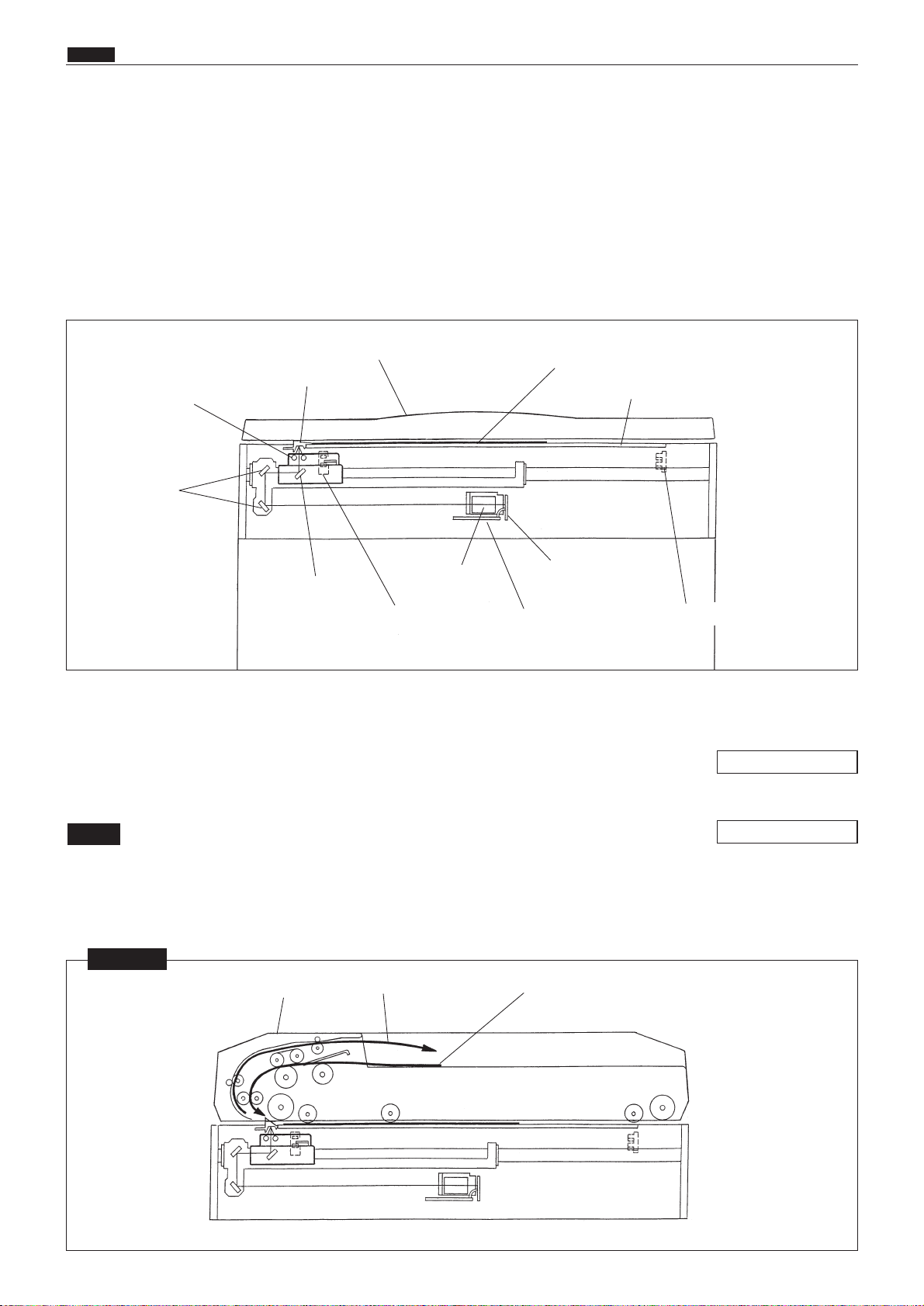
86
z Scanner Section
chap.2
zScanner Section
The document is illuminated with the lamps, and the document reflection in proportion to the document
image darkness is imaged at the CCD through the mirror lens. Then it is resoluted into picture elements and
is converted photoelectrically.
Optical driving of illuminating the document is the same for the document placed on the ADF and for the
document placed on the plate glass.
Optical operation
2The optical system goes forward (to the right) or backward with a stop position of PS1 (Stop position sen-
sor).
2PS2 detects opening and closing of the document cover and is used to read the document size and darkness.
2When the ADF is attached, the optical system does not read the document size since data for the document size is
received from the ADF.
NOTE
1. Description
\See page 90
\See page 91
2 ADF is attached
NOTE
ADF
Document is fed
Document is ejected
Document cover
Document
Glass
Virtical size plate
Lamps
Mirror
Mirror
Lens
AD PCB unit
CCD PCB unit
Home position sensor (PS 1)
Document cover sensor (PS 2)
Page 86
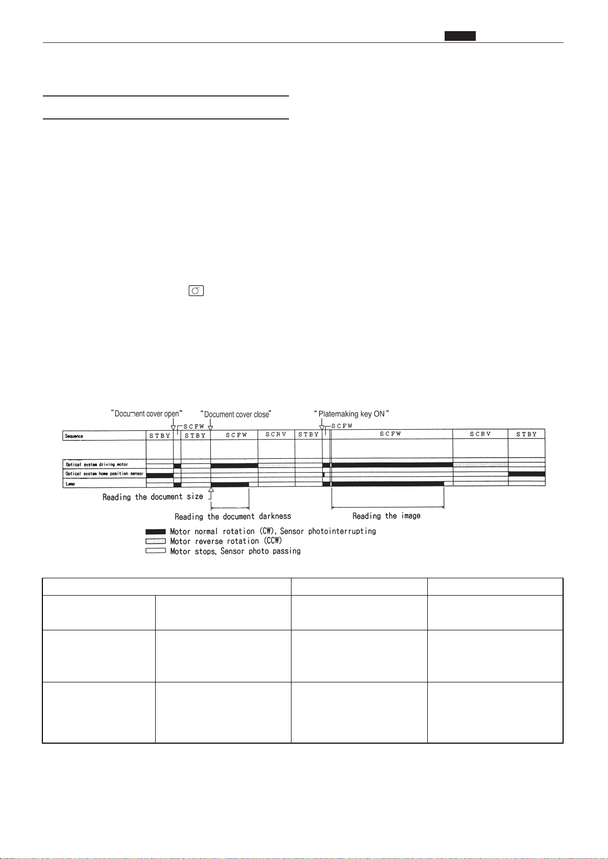
1) When the document cover is opened (PS2: photopassing) with the system in the standby state, the lamp
lights up, and the optical system moves to the document size reading position. When it reaches this position, the lamp goes out and the system returns to the standby state.
2) When the document cover is closed again (after having been opened in the standby state) (PS2: photointerrupting), the lamp lights up and the document size is read. When the document size is read, the optical system immediately moves to the right and reads the document darkness.
When document darkness reading is complete, the lamp goes out, but the optical system decelerates, then
stops. Following that, the optical system moves left and returns to the home position. The system is then in
the standby state.
3) When the PLATEMAKING key is pressed with the system in the standby state, the lamp lights up and
the system moves to the image reading start position. When it reaches this position, the system stops
momentarily, and the lamp goes out and comes on again, very rapidly. (This happens so rapidly that it cannot be observed with the naked eye.) Then the scanner moves to the right and reads the image. When
image reading is complete, the lamp goes out, but the optical system decelerates, then stops. Following
that, the optical system moves left and returns to the home position. The system is then on standby for the
printing process.
87
z Scanner Section
chap.2
(1) Sequence of the Scanner Operation
2. Sequence of Operation
Interval Purpose Remarks
STBY / Standby While the optical system is
stopped.
SCFW / Optical system
goes forward.
Until the optical system stops
after it starts to go forward.
It goes forward to move to the
document size reading position and to read the document
darkness and image.
Required time and frequency
varies depneding on the paper
setting, R / E or number of
prints per page.
SCRV / Optical system
goes backward.
Until the optical system which
has finished reading the document darkness and image
stops after it starts to go backward.
To return the optical system to
the home position.
Page 87

88
z Scanner Section
chap.2
When the document cover is opened at a certain angle, the document cover sensor
changes to be in the state of photopassing.
The lamps lights up, the optical system moves to the document size reading position
(about 30 mm from the top end of the document) and stops. The lamps light out.
When the document cover is closed at a certain angle, the document cover sensor
changes to be in the state of photointerrupting.
The lamps light up and the document size is read.
d
The optical system moves, and senses the document darkness. The movement distance is
determined according to the document size sensed.
The lamps light out and the optical system decreases the speed, stops and returns to the
home position.
1. Reading the Document Size
2The document size is read by detecting the photo amount. The reverse face of the document cover is white.
When the document cover is opened at a certain angle, the lamp light reaches the CCD as reflection light at
the document area. As there is no reflection light where the document is not placed, non-document area is
detected as "black" at the CCD.
The position which changes from black to white is detected as document size. Whether the document is
placed in the lateral direction or in the longitdinal direction is not detected since the primary scanning
direction is only detected.
2In this machine, the paper size is read as follows:
(1) The document darkness sensing area is determined.
(2) In the auto paper selection mode, the paper is selected based on the document size and zoom factor.
(3) In the auto zoom mode, the zoom factor is selected based on the document size and paper size.
2When the ADF is installed, data on the document size is sent from the ADF. The main body does not read
the document size.
2. Reading the Document Darkness
2The optical system goes forward to read
the document darkness immediately after
the document size is read.
2The area over which darkness is sensed is
determined according to the document
size sensed.
Vertical size plate tip end
Signal
Approx 30mm
Plate
glass
Document
255 0
Document size reading position
Darkness sensing area
d
d
d
d
(2)
Operation with the Document Cover Open / Closed
Page 88

89
z Scanner Section
chap.2
Platemaking Area for the Book Shadow Erasing Mode
When the platemaking is performed in the book shadow erasing mode, the platemaking area is limited 3
mm inner than the normal platemaking area as shown in the figure. 15mm is left in the central section
(stitching section).
* During multiple image printing or when paper size is set to A4, the book shadow erasing mode can not
be used.
Platemaking Area for the Selected Paper
2The platemaking area varies depending on the selected paper size as shown below.
: DP-43E/S, 33E/S, 31E/S
* When the magnification error is 0 in the primary
scanning direction or in the secondary scanning
direction, the size for the same size (1:1) platemaking is shown.
NOTE
Selected
paper size
A3
A4
R
B4
A5
B5
LDG
11"914"
LTR
STMT
MAX
A4
A (±1%)
291mm
204
251
142
176
273
251
210
172
291
291
B (±1%)
414mm
291
358
204
251
414
358
273
210
414
204
Model
(DP-43E/S)
(DP-43E/S)
(DP-33E/S, 31E/S)
(DP-43E/S)
LGL 210 350
MINI
(DP-33E/S, 31E/S)
134 210
Page 89

90
z Scanner Section
chap.2
Operation
Sensor plate for the PS1 is installed to slider A,
optical system. The home position of the optical
system is the position where the PS1 is photointerrupted.
As shading is conducted at the home position, the shading plate is in alignment with the center line of the
mirror at the home position. The shape of the vertical size nameplate is different depending on whether
the ADF is installed or not. But the home position is the same.
Description
The home position sensor detects the original position for the optical system.
Circuit
3. Function of Parts
(1) Home Position Sensor
NOTE
Home position
sensor (PS 1)
Sensor plate
Slider A
Slider A
Slider B
Control panel
Shaft
Home position sensor (PS 1)
Slider A
ADF is not attached ADF is attached
Shading plate
Shading plate
Glass
Vertical size plate
Vertical size plate
Lamp
Lamp
Mirror
Page 90
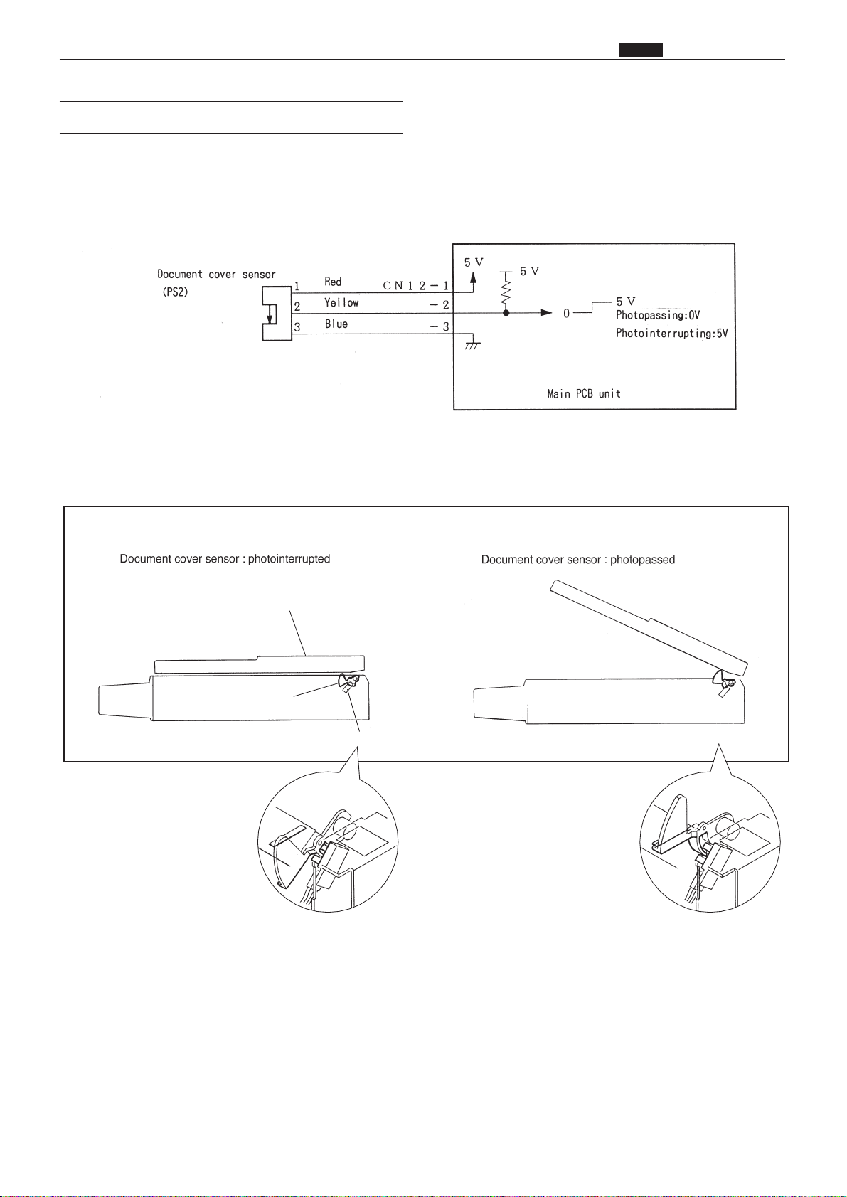
91
z Scanner Section
chap.2
Description
The document cover sensor detects opening and closing of the document cover (or ADF if the ADF is installed).
Operation
Sensor PS2 is photointerrupted with the document cover closed, The photointerrupter rotates as the
document cover is opened and sensor PS2 is photopassed.
Circuit
(2) Document Cover Sensor
2When the document cover is closed 2When the document cover is opened
PS2
Photointerrupting plate
Document cover
Page 91

92
z Scanner Section
chap.2
Description
The lamps illuminate the document, and the reflection light is transmitted to the CCD. The image signal is
output from the CCD by the voltage level. The signal from the CCD is transmitted to the AD PCB Unit and
converted.
Specifications
2Lamp
Xenon arc lamp is used for this machine. it is excellent in starting up when the lamp is lit, and the photo
amount is stable. Since two lamps are used, less shadow is produced for a patched document.
2CCD
No. Item DP-43E/S, 33E/S
1 Optical signal storage time 1.6msec/line
2 Frequency 3.375MHz
3
The number of effective picture
elements
4800 picture elements
4
Reading width
(This is not the image width
which can be processed)
305mm
5 Reading density 400DPI(15.7dot / mm)
DP-31E/S
2.048msec/line
300DPI(11.8dot / mm)
Circuit
(3) CCD / Lamps
Page 92

93
z Scanner Section
chap.2
Operation
When the
scanner unit
is closed, the switch is pressed; OPEN. the switch is attached to the plate spring,
which keeps the switch from too much pressure. When the
scanner unit
is open, the actuator is released; the
micro switch is turned to CLOSE.
Description
Opening and closing of scanner unit cover is detected by scanner unit cover open / close detection SW (MS3).
This machine does not work (except for the master setting SW and the jog SW) unless the scanner unit is
closed firmly. The machine stops immediately when the scanner unit is open. (after finishing platemaking if
platemaking is being performed.)
• When the scanner unit is opened
•When the scanner unit is closed
Circuit
(4) Scanner Unit Open / Close Detection
Page 93
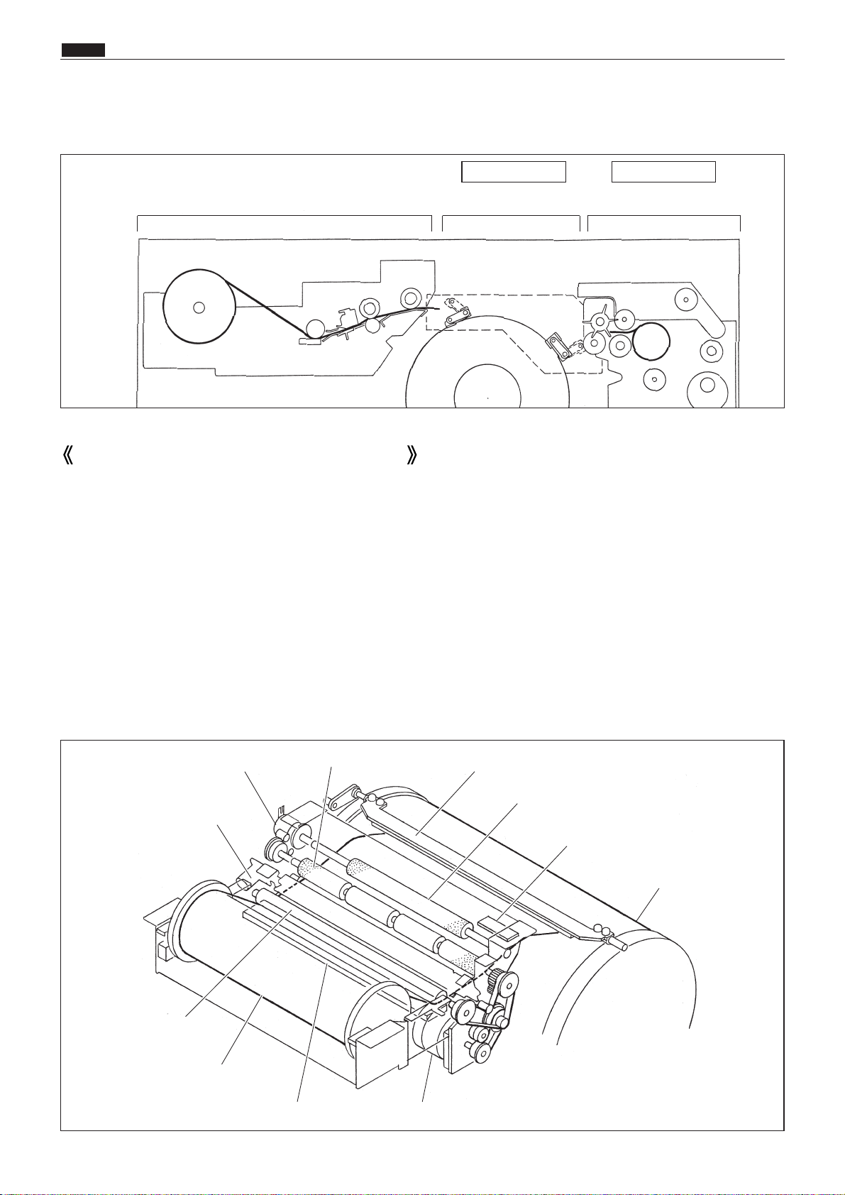
94
x Pratemaking / Master Feed / Ejection Section
chap.2
xPlatemaking / Master Feed / Ejection Section
Make the master clump of the drum unit clump the master top end, performing platemaking on the master
with the thermal head. (In this machine, the master on the drum is ejected at the same time when platemaking is performed.)
The master is conveyed to the drum unit via the platen roller and sponge rollers 1 and 2 by driving of the
stepping motor, while it is being processed in the head section. Sponge roller 2 is driven through the master
feeding clutch (electromagnetic clutch), and controls the amount of master conveyed to the master clump section of the drum unit with the master feeding clutch ON / OFF.
The end mark sensor starts to detect when the end mark (black) section printed on the end of the roll master
is conveyed. "CHANGE MASTER" is displayed on the error display panel. The endmark sensor also detects
whether the master is conveyed properly through the sensor.
Cutter unit
Master feeding clutch
Sponge roller 1
Master clump
Sponge roller 2
Endmark sensor
Drum
Platen roller
Roll master
Thermal head Stepping motor
1. Description
Platemaking / Master Feed Section
Platemaking / Master Feed section
Master Clump Opening /
Closing Section
Master Ejiction Section
See page 107See page 109
Page 94

95
x Pratemaking / Master Feed / Ejection Section
chap.2
When the master set switch is pressed, the platen
roller and sponge roller 1 rotate and the master is
fed for about 3 seconds and it stops.
The cutter cuts the master, by executing 1
reciprocating motion.
The master is fed for some time after the cutter
limit SW is ON.
*Fed amount is the same as the amount fed after
the master is cut for platemaking.
Master
*Top view of the plate
feeding section
Cutter Limit SW
(Rearside)
(MS2)
Sponge roller 1
Sponge roller 2
Cutter Limit SW
(Operationside)
(MS1)
Sponge roller 1
Platen roller
Stepping motor
Master
set switch
Cutter
2. Sequence of Operation
(1)
Sequence with the Master Set Switch ON
HELP mode H-29 \ see p.335
Page 95
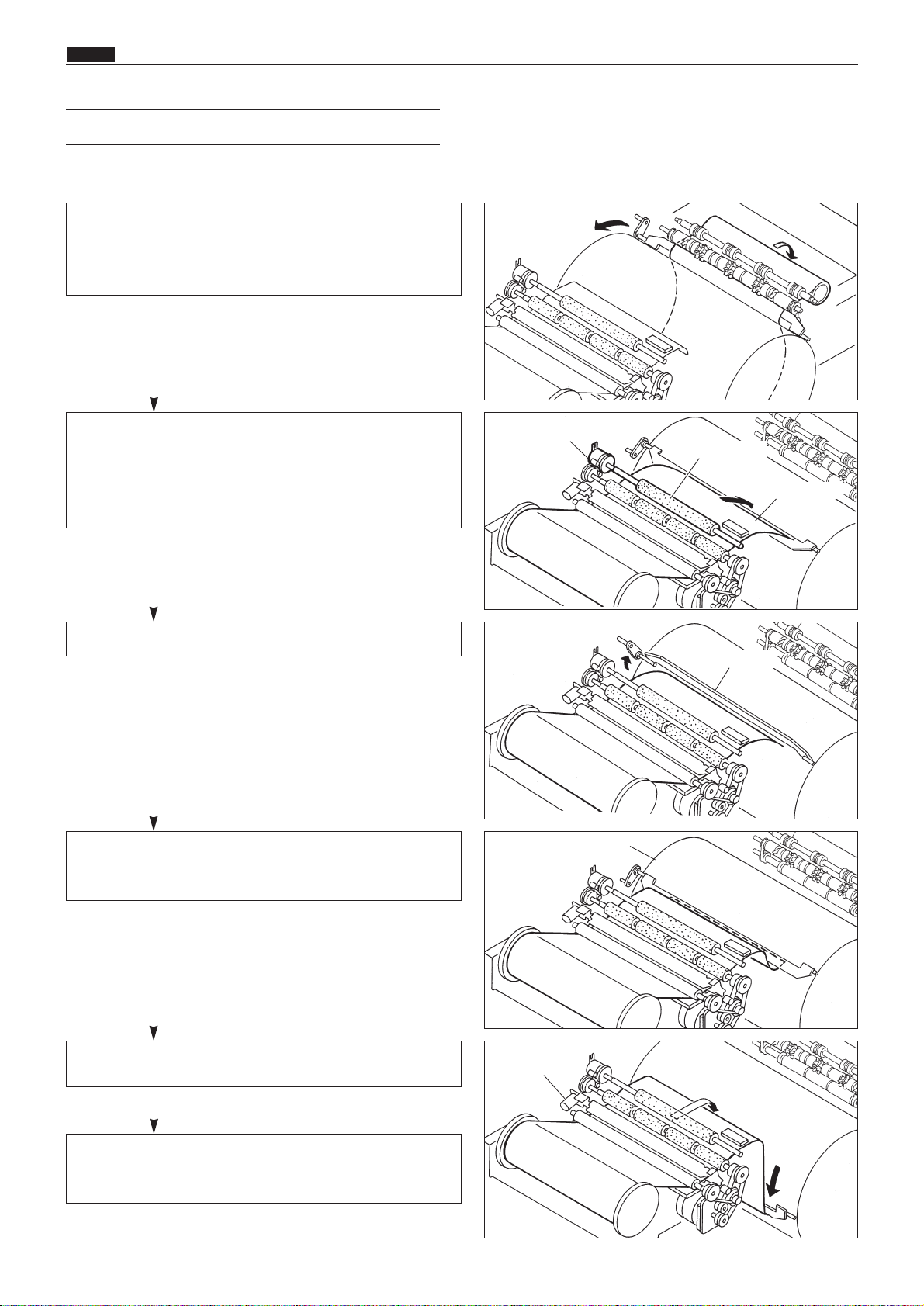
96
x Pratemaking / Master Feed / Ejection Section
chap.2
Operation
When platemaking operation starts, the drum unit
rotates to perform plate detachment process. The
drum which has finished plate detachment process
stops at the plate attachment position.
Open the master clump.
Sponge roller 2 rotates with the master feeding
clutch ON. A certain amount of the master tip end
is fed to the master clump section and the sponge
roller stops.
Open the master clump
After the master clump is closed and clump the
master tip end, the drum rotates to roll up the
master.
After finishing platemaking, the cutter cuts the
master.
When the master bottom end reaches the top of the
drum, plate attachment is completed. Commence
printing.
Master feeding clutch
Sponge roller 2
Master tip end
Master clump
Drum
Cutter
*Check the length of the master and
drum rotation angle to control the
drum rotation.
*As the electromagnetic clutch is OFF,
the sponge roller is free.
(2) Platemaking / Master Feeding
Page 96

97
x Pratemaking / Master Feed / Ejection Section
chap.2
(1)Thermal Head
Description
The thermal elements are in alignment in the scanning direction, and are heated on the image section to
make holes on the master film.
Specifications
No.1No. Item DP-43E/S DP-33E/S DP-31E/S
1 Picture element density 400DPI(15.7dot /mm) 300DPI(11.8dot /mm)
2 Effective memory width 292.6+_0.1mm 260.1+_0.1mm 260.2+_0.2mm
Circuit
3. Functions of Parts
Page 97
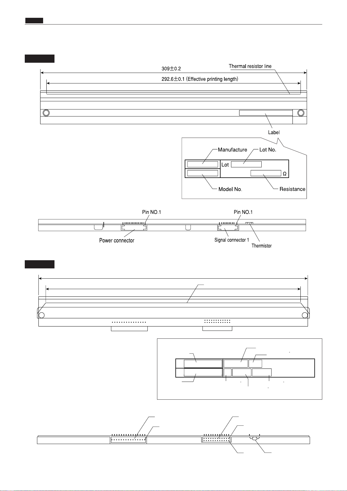
98
x Pratemaking / Master Feed / Ejection Section
chap.2
Exterior and Lot No.
DP-43E/S
DP-33E/S
Thermistor
Signal connector
No.1
No.2
No.1
Power connector
Thermal resistor line
276.5±0.5
260.1±0.1
東芝マーク
型名
ヘッド抵抗値ランク
ヘッド平均抵抗値
電圧表示
ロット番号
製品番号
Toshiba
marker
Model
name
Lot No.
Product No.
Head resistance ranking
Head average resistance
Voltage indication
Page 98

99
x Pratemaking / Master Feed / Ejection Section
chap.2
Lot No.
Lot No. is shown with 4 digits including alphabet. Each digit has the following meanings.
Serial No. in the production month
Production month (See the table)
Production year (Year of decade)
ABCDEFGHI JKL
Jan. Feb. Mar. Apr. May. Jun. Jul. Aug. Sep. Oct. Nov. Dec.
Sign
Month
NOTE
DP-31E/S
Lot No.
Model name
Head average resistance
Lot No.
Product No.
275.5±0.5
260.2±0.2
Power connector
No.1
Thermal resistor line
Signal connector
No.2
No.1
Thermistor
Page 99

100
x Pratemaking / Master Feed / Ejection Section
chap.2
Resistance
Resistance value is described on the label. When the head is replaced and the HELP mode is initialized, set the DIP-SW (H-43, H-44) of the HELP mode.
NOTE
HELP mode H-43, 44 \ see p.344
Resistance
DP-43E/S
DP-33E/S
Rank
Resistance value(Ω)
H-43 H-44
0
1890 〜 1962
0101 0101
1
1963 〜 2038
0101 0111
2
2039 〜 2117
0110 0101
3
2118 〜 2199
0110 0111
4
2200 〜 2285
0111 0100
5
2286 〜 2373
0111 0111
6
2374 〜 2465
1000 0100
7
2466 〜 2560
1000 0110
Rank
0 1890 - 1926 0110 0100
1 1927 - 1964 0110 0101
2 1965 - 2002 0110 0110
3 2003 - 2044 0110 0111
4 2045 - 2085 0111 0100
5 2086 - 2126 0111 0101
6 2127 - 2167 0111 0110
7 2168 - 2234 0111 0111
8 2235 - 2279 1000 0100
9 2280 - 2324 1000 0101
10 2325 - 2369 1000 0110
11 2370 - 2403 1000 0111
12 2404 - 2451 1001 0100
13 2452 - 2499 1001 0101
Resistance value( )
H-43 H-44
14 2500 - 2547 1001 0110
15 2548 - 2560 1001 0111
Page 100

101
x Pratemaking / Master Feed / Ejection Section
chap.2
DP-31E/S
Rank
Resistance value(Ω)
H-43 H-44
0
2620 〜 2716
1010 0010
1
2717 〜 2816
1011 0000
2
2817 〜 2920
1011 0010
3
2921 〜 3028
1100 0001
4
3029 〜 3140
1100 0011
5
3141 〜 3255
1101 0001
6
3256 〜 3376
1101 0011
7
3377 〜 3500
1110 0010
 Loading...