

Page 1

INSTRUCTION MANUAL
Perfect Binder
DuBinder
Be sure to read this manual prior to use.
Please leave this manual at the site of use for easy reference.
DPB-500
Page 2

Direttiva sui macchinari 98/37/CE e 2006/42 CE in base a
EN 1010-1: 2004, EN 1010-4: 2004, EN 60204-1: 2006
Direttiva relativa alle apparecchiature a bassa tensione
2006/95/CE in base a IEC 60950-1: 2001 incluse deviazioni
EN 60950-1: 2001+ A11: 2004
Direttiva di compatibilità elettromagnetica 89/336/CEE e
2004/108/CE in base a EN 61000-3-2: 2006, EN 61000-3-3:
1995+A1: 2001+A2: 2005,
EN 61000-6-2: 2001,
EN 61000-6-4: 2001
It
Directiva sobre máquinas 98/37/CE y 2006/42/CE, según
EN 1010-1: 2004, EN 1010-4: 2004, EN 60204-1: 2006
Directiva sobre baja tensión 2006/95/CE, según IEC
60950-1: 2001, incluyendo las derogaciones EN 60950-1:
2001+ A11: 2004
Directiva sobre compatibilidad electromagnética 89/336/CEE
y 2004/108/CE, según EN 61000-3-2: 2006, EN 61000-3-3:
1995+A1: 2001+A2: 2005, EN 61000-6-2: 2001,
EN 61000-6-4: 2001
Sp
Directive Machines 98/37/CE et 2006/42/CE en application
des normes EN 1010-1: 2004, EN 1010-4: 2004 et
EN 60204-1: 2006
Directive Basse tension 2006/95/CE en application de IEC
60950-1: 2001, dérogations selon EN 60950-1: 2001
+A11: 2004 incluses
Directive sur la compatibilité électromagnétique 89/336/CEE
et 2004/108/CE en application des normes EN 61000-3-2:
2006, EN 61000-3-3: 1995+A1: 2001+A2: 2005,
EN 61000-6-2: 2001, EN 61000-6-4: 2001
Fr
Maschinenrichtlinie 98/37/EG und 2006/42 EG unter
EN 1010-1: 2004, EN 1010-4: 2004, EN 60204-1: 2006
Niederspannungsrichtlinie 2006/95/EG unter
IEC 60950-1: 2001 einschließlich EN 60950-1: 2001
+ A11: 2004 Abweichungen
Richtlinie zur elektromagnetischen Verträglichkeit
89/336/EWG und 2004/108/EG unter EN 61000-3-2: 2006,
EN 61000-3-3: 1995 + A1: 2001 + A2: 2005,
EN 61000-6-2: 2001, EN 61000-6-4: 2001
Ge
KONFORMITÄTSERKLÄRUNG
Die DUPLO CORPORATION mit Sitz in 1-6, Oyama 4-chome,
Sagamih ara -shi,
Kanagaw a-k en 229 -11 80, Japan , erklärt
hiermit, dass das folgende Produkt,
• Bezeichnung des Produkts :
Bindemaschine
• Modell :
DPB-500
den nachfolgend aufgelisteten Richtlinien entspricht:
• Richtlinien :
DICHIARAZIONE DI CONFORMITÁ
DU P L O CO RPORATI O N si ta a 1- 6 , Oy ama 4-chome ,
Sagamihara-shi, Kanagawa-ken 229-1180 Japan, dichiara che il
seguente prodotto,
• Nome del prodotto :
macchina cucitrice per legatoria
• Modello :
DPB-500
è conforme ai requisiti definiti dalle norme sotto elencate:
• Direttiva Bassa Tensione :
DECLARATION OF CONFORMITY
DUPLO CORPORATION, located at 1-6, Oyama 4-chome, Sagamihara-shi, Kanagawa-ken 229-1180, Japan, declares
that the following product,
• Name of product : Binder
• Model : DPB-500
complies with the provisions defined by the regulations listed below.
• Regulation : Machinery Directive 98/37/EC and 2006/42/EC under EN 1010-1: 2004, EN 1010-4: 2004, EN 60204-1: 2006
Low Voltage Directive 2006/95/EC under IEC 60950-1: 2001 including EN 60950-1: 2001+A11: 2004 deviations
Electromagnetic compatibility Directive 89/336/EEC and 2004/108/EC under EN 61000-3-2: 2006,
EN 61000-3-3: 1995+A1: 2001+A2: 2005, EN 61000-6-2: 2001, EN 61000-6-4: 2001
En
DECLARACIÓN DE CONFORMIDAD
DUPL O CORPORA TION, con domicilio en 1-6, Oyama
4-chome,
Sagamihara-shi, Kanagawa-ken 229-1180 Japan,
declara que el producto siguiente :
• Nombre del producto :
Encuadernadora
• Modelos :
DPB-500
cu m p le con l o dispues t o por lo s reglamen t o s que s e
in d i can a c o n tinuació n .
• Reglamentaciones :
DECLARATION DE CONFORMITE
DUPLO CORPORATION, située à 1-6, Oyama 4-chome,
Sagamihara-shi,
Kanagawa-ken 229-1180, Japon, déclare que le
produit suivant ;
• Nom du produit :
Relieuse
• Modèle :
DPB-500
est conforme aux dispositions définies par les réglementations
suivantes :
• Réglementations :
Page 3

Disposal of Old Electrical & Electronic Equipment
This symbol (the symbol of the crossed out wheeled
bin) indicates that in European countries this product
should not be disposed of as household waste.
Please recycle where facilities exist by checking with
your local authority or supplier for recycling advice.
By ensuring this product is disposed of correctly
through proper treatment, recovery and recycling,
you will help prevent potential negative e
ffects on the
environment and human health.
En
Entsorgung von alten elektrischen und
elektronischen
Ausrüstungsteilen
Dieses Symbol (das Symbol mit dem durchgekreuzten
fahrbaren Müllbehälter) zeigt an, dass dieses Produkt
in europäischen Länden nicht als Haushaltsmüll
entsorgt werden darf. Bitte informieren Sie sich bei
Ihren örtlichen Behörden oder bei Ihrem Händler
hinsichtlich einer Empfehlung für die Entsorgung
und führen Sie die betre
ffenden Teile dort, wo solche
Einrichtungen vorhanden sind, einem RecyclingProzess zu.
Indem sie sicherstellen, dass das betre
ffende Produkt
durch richtige Behandlung, Rückführung und Recycling
entsorg
t wird, tragen Sie dazu bei, möglichen negativen
Auswirkungen auf die Umwelt und die menschliche
Gesundheit vorzubeugen.
Ge
Elimination du matériel électronique et électrique
usagé
Ce symbole (une poubelle marquée d’une croix)
indique que dans les pays européens, ce produit ne
doit pas être éliminé comme des ordures ménagères.
Recyclez-le dans les sites adaptés qui vous seront
indiqués par les autorités locales ou renseignez-vous
auprès de votre fournisseu
r.
En veillant à ce que ce produit soit éliminé
correctement avec un traitement, une collecte et un
recyclage adaptés, vous contribuez à éviter son action
nocive potentielle sur l
’ environnement et la santé
humaine.
Fr
Smaltimento di attrezzature elettriche ed
elettroniche consumate
Questo simbolo (il simbolo della pattumiera con rotelle
barrata) indica che nei paesi europei questo prodotto
non deve essere buttato nei ri
fiuti domestici.
Per favore smaltire in luogo addetto al riciclo, dove
esistente, chiedendo informazioni alle autorità locali o
a chi fornisce consulenza a proposito.
Garantendo uno smaltimento adeguato di questo
prodotto (trattamento, recupero e riciclo corretto),
aiuterete a prevenire e
ffetti negativi sull’ambiente e
sulla salute dell’uomo.
It
Eliminación de residuos de aparatos eléctricos y
electrónicos
Este símbolo (un cubo de basura tachado) indica
que en los países europeos este producto no deberá
eliminarse como si se tratara de un residuo doméstico.
Solicite asesoramiento sobre reciclaje a las autoridade
s
locales o a su distribuido
r, y siga la normativa en
materia de gestión medioambiental y reciclaje de este
tipo de residuos.
Si toma las medidas pertinentes para que este
producto se elimine mediante un tratamiento,
recuperación y reciclaje adecuados, contribuirá a evitar
posibles efectos negativos en el medio ambiente y la
salud humana.
Sp
Page 4

Note: This symbol mark is for EU countries only.
This symbol mark is according to the directive 2006/66/
EC
Article 20 Information for end-users and Annex II.
This symbol means that batteries and accumulators, at
their end-of-life, should be disposed of separately from
your household waste.
If a chemical symbol is printed beneath the symbol
shown above, this chemical symbol means that the
battery or accumulator contains a heavy metal at a
certain concentration.
This will be indicated as follows:
Hg: mercury (0.0005%), Cd: cadmium (0.002%),
Pb: lead (0.004%)
In the European Union there are separate collection
systems for used batteries and accumulators.
Please, dispose of batteries and accumulators correctly
at your local community waste collection/recycling
centre.
Note:
You do not need to replace the battery for
this machine by yourself.
En
Nota: questo contrassegno interessa soltanto i
Paesi UE
It
Questo contrassegno è conforme alla direttiva
2006/66/CE Articolo 20 Informazioni per gli utenti finali
e Appendice II.
Indica che le batterie e gli accumulatori, una volta
esauriti, devono esssere gettati separatamente dai rifiuti
domestici.
Se sotto il simbolo mostrato qui sotto è stampato un
simbolo chimico, quest'ultimo indica che la batteria o
l'accumulatore contiene un metallo pesante in una
determinata concentrazione. Ciò verrà indicato come
segue:
Hg: mercurio (0.0005%), Cd: cadmio (0,0002%),
Pb: piombo (0.004%).
Nei Paesi dell'Unione Europea esistono sistemi di
raccolta diversi per le batterie e gli accumulatori usati.
Vi preghiamo di smaltire le batterie e gli accumulatori
correttamente presso il vostro centro di smaltimento
rfiuti/ riciclo locale.
Nota: non dovete sostituire da soli la batteria di
questa macchina.
Nota: Este símbolo sólo sirve para países de la UE.
Sp
Este símbolo cumple lo dispuesto en el Artículo 20 Información para los usuarios finales y el Anexo II de la
Directiva 2006/66/EC.
Este símbolo significa que las pilas y los acumuladores,
al finalizar su vida útil, deben eliminarse a parte de los
residuos habituales de su hogar.
Si debajo del símbolo que se muestra más arriba
aparece un símbolo de producto químico, entonces
este símbolo significa que la pila o el acumulador
contienen cierta concentración de metal pesado. Ello se
indica del siguiente modo:
Hg: mercurio (0,0005%), Cd: cadmio (0,002%),
Pb: plomo (0,004%).
En la Unión Europea existen sistemas separados para
la recogida de pilas y acumuladores usados.
Le rogamos que elimine las pilas y los acumuladores
correctamente en su centro local de recogida/reciclaje
de residuos.
Nota: No es necesario que usted mismo cambie la
pila de este aparato.
Hinweis: Diese Symbol-Markierung gilt nur für EULänder.
Ge
Diese Symbol-Markierung entspricht der Direktive
2000/66/EG Artikel 20 Informationen sowie Anhang II.
Dieses Symbol bedeutet, dass verbrauchte Batterien
getrennt vom Haushaltsmüll zu entsorgen sind.
Wenn ein chemisches Symbol unter das oben
dargestellte Symbol gedruckt ist, so bedeutet dieses
chemische Symbol, dass die Batterie oder der Akku ein
Schwermetall in einer bestimmten Konzentration
enthält, Dies wird wie folgt angezeigt:
Hg: Quecksilber (0,0005 %), CD: Cadmium (0,002 %),
Pb: Blei (0,004 %)
In der Europäische Union gibt es separate
Sammelsysteme für verbrauchte Batterien und Akkus.
Bitte entsorgen Sie die Batterien und Akkus
vorschriftsmäßig in Ihrem örtlichen
Müllsammel-/Müllrecycling-Zentrum.
Hinweis: Sie brauchen die Batterie für diese
Maschine nicht selbst auszutauschen.
Remarque : Ce symbole n’est valable que pour les
pays de l’UE.
Fr
Ce symbole est conforme à la directive 2006/66/CE,
Article 20 Informations destinées aux utilisateurs finaux
et Annexe II.
Ce symbole signifie que les batteries et accumulateurs,
une fois arrivés en fin de vie, ne doivent pas être jetés
avec les ordures ménagères.
Si un symbole chimique est imprimé au-dessous du
symbole indiqué ci-dessus, ce symbole chimique
signifie que la batterie ou l’accumulateur contient un
métal lourd atteignant une certaine concentration. Ceci
sera alors indiqué de la façon suivante :
Hg : mercure (0,0005 %), Cd : cadmium (0,002 %),
Pb : plomb (0,004 %)
Il existe dans l’Union Européenne des systèmes de
collecte distincts pour les piles et accumulateurs.
Veuillez déposer vos batteries et accumulateurs dans
votre centre local de recyclage ou de collecte des
déchets.
Remarque : Vous n’avez pas besoin de remplacer
vous-même la batterie de cette machine.
.
Page 5

Note:
This equipment has been tested and found to comply with the limits for a Class A digital device,
pursuant to Part 15 of the FCC Rules. These limits are designed to provide reasonable protection
against harmful interference when the equipment is operated in a commercial environment. This
equipment generates, uses, and can radiate radio frequency energy and, if not installed and used in
accordance with the instruction manual, may cause harmful interference to radio communications.
Operation of this equipment in a residential area is likely to cause harmful interference in which case
the user will be required to correct the interference at his own expense.
Page 6

Introduction
Thank you for purchasing a Duplo product.
Be sure to read this manual prior to using the product.
After reading, leave the manual at the site of use for easy reference whenever questions related to the
product arise in the future.
Symbols
In this manual, several symbols are used to indicate important warnings. Please make sure to read
instructions accompanied by these symbols. These symbols have the following
meanings.
Describes instructions which must be followed in use.
Be sure to read the instructions to avoid problems due to incorrect operations.
Indicates supplementary or useful information.
Describes names of related items and supplementary instructions.
Trademark
The product name and company name used in this manual are trademarks or registered trademarks
of the respective companies.
Page 7

i
Safety Precautions
Safety Precautions
In this manual, operations and handling of the unit which are hazardous are described using the
following marks to prevent personal injury or property damage to the user and others.
Ignoring this mark could result in the possibility of
serious injury or even death.
Ignoring this mark could result in the possibility of injury
or physical damage.
This mark indicates a “Warning” or “Caution”.
A graphic may be shown inside the mark to describe the warning or caution more specifically.
This mark indicates a forbidden action.
A graphic may be shown inside the mark to describe the forbidden action more specifically.
This mark indicates actions that must be performed.
A graphic may be shown inside the mark to describe the action to be performed more specifically.
Power Supply
● This unit shall be installed near the socket-outlet where the plug on the power supply cord is easily
accessible.
● Make sure the power supply used is always within the following range.
Power supply : Y208V,
240V AC (three-phase), 60 Hz (USA, Canada)
Y380 to Y415 V AC (three-phase), 50/60 Hz (Europe)
● When you power other appliances from the same AC outlet, make sure that the combined power
consumption does not exceed the power supply capacity.
Rated current (Rated power) : 3.2 kW AC (three-phase 208 V, 240 V 60Hz) 8 A/single-phase
(USA, Canada)
3.2 kW AC (three-phase 380 to 415 V 50/60Hz) 5 A/single phase (Europe)
Use only the power supply voltage specified on the main nameplate.
Using other voltages could result in a fire or an electrical shock.
Make sure that the combined power consumption of the appliances to be
connected does not exceed the capacity rating of the power outlets or plug
receptacles.
Exceeding the capacity rating could cause the power outlets, plug receptacles, or power extension
cords to overheat and catch a fire.
High touch current
Earth connection essential before connecting supply.
Page 8

ii
Safety Precautions
Operating Environment
Operate this unit in the following environment.
● where the temperature range is between 5 and 35°C/41 and 95°F (-10 to +50°C/ 14 to 122°F) in
storage)
● where the humidity range is between 10 and 85% RH (10 to 90% RH in storage, however no
condensation)
● which is not subject to direct sunlight
● which is reasonably free from dust
● which is subject to little or no vibration
● which is free from air-borne salt
● where there are no harmful chemicals
● where the unit is not exposed to water
Keep this unit and the power cord away from heaters and heater vents.
Excessive heat could melt the cover or power cord covering, and result in a fire or an electrical shock.
Do not place metal objects or vessels containing liquids on top of the unit.
The entry of any metal object or liquid could result in a fire or an electrical shock.
Do not insert any metal or easily-combustible object inside this unit.
This could result in a fire or an electrical shock.
Do not use flammable sprays inside or near the unit (e.g. when cleaning the
unit).
Such flammable gas may ignite and cause a fire or combustion.
Do not install this unit in a location where there is excessive humidity or where
contact with water is possible.
Poor choice of location could result in deterioration of the insulation, a fire or an electrical shock.
Install this unit on a level, stable stand or floor, with sufficient space around it.
Failure to do so could result in the unit overturning and causing injury.
Disconnect the power plug from the power outlet before attempting to move
this unit.
Failure to do so could result in power cord damage, a fire or an electrical shock.
Always disconnect the power plug from the power outlet when the unit is not
to be used for an extended period.
Failure to do so could result in a fire due to leakage current if the insulation should deteriorate.
Page 9

iii
Safety Precautions
Do not damage the power cord or power plug.
Do not scratch, alter, bend, twist, pull or place heavy objects on the power cord or power plug.
This could result in damage, a fire or an electrical shock.
Do not touch the power switch with wet hands.
Otherwise electric hazards may occur.
Do not remove the cover or back panel.
This unit contains high-voltage components that could cause an electrical shock.
Do not disassemble, modify or repair this unit.
There is a danger of fire, electrical shock or injury.
Contact your dealer when repairs are necessary.
If any foreign object such as metal or liquid should enter this unit, immediately
turn the unit off at the power switch and disconnect the power plug from the
power outlet.
Failure to do so could result in a fire or an electrical shock.
Contact your dealer immediately.
Before cleaning this unit, turn the unit off at the power switch and disconnect
the power plug from the power outlet.
Accidental operation of the unit during cleaning could result in injury.
Remove any dust that accumulates on the power plug prongs and the surface
of the plug from which the prongs extend.
Accumulated dust could result in a fire.
Always grip the plug when disconnecting the power plug from the power
outlet.
Forcibly pulling on the power cord could cause damage, resulting in a fire or an electrical shock.
Do not touch or insert foreign objects into any rotating part during operation.
This could result in injury.
Maintenance / Others
Page 10

iv
Safety Precautions
Hot Melt Glue
Do not block off the hume exhaust.
This unit exhausts vaporized hot melt glue to the outside of the unit using the fan. If the hume exhaust
is blocked off, the fumes that stay inside the unit may cause fire.
Attach a hume exhaust hose to the hume exhaust of this unit so that the fumes
can be exhausted outdoors or to a well-ventilated place.
The fumes are generated while the hot melt glue is being melted at high temperatures. The fumes
may irritate your eyes, nose and throat. If you do not feel well, go out into the fresh air. If you still feel
sick, get prompt medical attention.
Read carefully the precautions for handling the hot melt glue you are going to
use.
Because the hot melt glue is combustible, do not put the glue close to fire.
It may cause a burn injury or fire.
When you handle the hot melt glue, make sure that you wear protection
gloves, long-sleeved clothes, eye protectors to prevent burn injuries.
In case the liquefied or vaporized hot melt glue gets into your eye or is attach to your skin, cool it with
cold water immediately and get prompt medical attention.
Page 11

v
Safety Precautions
WARNING / CAUTION Labels
"WARNING" and "CAUTION" labels are pasted on the machine to ensure user safety.
Do not remove or change them.
When the labels become dirty or are lost, be sure to contact your dealer for a new one.
WARNING
Do not put hands inside
during operation.
It may injure you.
Page 12

vi
Safety Precautions
Details on Warning and Caution Label
Label Explanation
Do not touch the milling blade and roughening blade during
machine operation. This may cause you severe injury.
High voltage of electricity supplied to the glue tank may cause
an electric shock. Be careful.
Because the touch current is high, make sure that a ground
connection is provided before connecting the power cord.
The glue tank temperature is very high.
When pressing a book block against the support clamp, be
careful not to get your hand caught in it.
When opening a main cover, be careful not to get your hand
caught in it.
Do not touch the nipping section while the machine is in
operation. Your fingers may get caught in the nipper.
Do not touch the nipping section while the machine is in
operation. Your fingers may get caught in the nipper.
Do not put your hand inside the machine while the paper feed
tray is moving. It may injure you.
Do not take out booklets during machine operation. This may
cause unexpected injuries.
There are high voltage parts inside the machine. Do not
remove the cover.
Before discharging glue from the tank, switch the machine to
the glue discharge mode.
Leaving the tank without glue inside may cause a malfunction
to the machine.
Glue discharged from the tank is very hot. Be careful not to
burn yourself.
Page 13

vii
Safety Precautions
Contents
Safety Precautions .....................................i
Power Supply ...................................................... i
Operating Environment .......................................ii
Maintenance / Others .........................................iii
Hot Melt Glue .....................................................iv
WARNING / CAUTION Labels ...........................
v
Chapter 1
BEFORE OPERATION
1. Features .............................................1-2
2. Workflow ............................................
1-3
3. Names and Functions ......................1-4
3-1. External Parts ........................................ 1-4
3-2. Milling Section .......................................
1-5
3-3. Glue
Tank Section ................................. 1-6
3-4. Nipping Section .....................................
1-7
3-5. Scoring Section .....................................
1-8
3-6. Feed Section .........................................
1-9
3-7. Delivery Section .................................. 1-10
4. Screen Descriptions ....................... 1-11
4-1. Settings Screen for Binding ................. 1-11
4-2. Fine-adjustment Screen ......................
1-11
4-3. Motion Check Screen ..........................1-12
4-4. Option Setting Screen ......................... 1-13
5. Accessories ....................................1-14
7.
Precautions on Hot Melt Glue ...............1-16
8. Cautions for Handling ....................1-17
9. Emergency Stop .............................1-18
10. Paper Size .......................................1-19
10-1. Cover and Book Block Size ................. 1-19
10-2. Book Block Thickness and
Cover Weight ......................................1-19
10-3.
Using Single-folded or Double-folded
Paper ....................................................1-20
10-4 Cover Type ..........................................1-20
Chapter 2
PREPAR
ING FOR
OPERATIO
N
1. Turning On the Power ......................2-2
2. Preparing Hot Melt Glue ...................2-3
3. Preparing Each Section ...................2-6
3-1. Level Plate ............................................2-6
3-2. Glue Tank .............................................. 2-7
3-3. Nipping Section ..................................... 2-8
3-4. Replacing the Receiving Tray with
the Stacker Stopper ..............................2-9
3-5. Replacing the Stacker Stopper with
the Receiving Tray .............................. 2-10
4. Entering Job Information ...............2-12
4-1. Cover (With a cover/Without a
cover) .................................................. 2-12
4-2. Setting Double Feed Detection for
Cover .................................................. 2-14
4-3. Setting Book Block Size ...................... 2-16
4-4. Setting the Cover Size ........................2-18
4-5. Cover Base Spine Position .................2-19
4-6. Checking and Saving Settings ............ 2-21
Chapter 3
STARTING BINDING
OPERATIO
N
1. Placing a Book Block .......................3-2
2. Test-Feeding a Cover .......................3-6
3. Starting Binding ..............................3-14
4. Removing the Booklet ....................3-17
5. Adding Covers ................................3-20
6. Finishing Binding ...........................3-21
7. Using Supplied Parts .....................3-23
8. Using Wing Scoring ........................3-25
Page 14

viii
Safety Precautions
Chapter 4
FINE-ADJUSTMENT AND
OPTION SETTING
1.
Fine adjusting Each Part ..................4-2
1-1. Setting the Paper Feed Guide ............... 4-2
1-2. Setting the Scoring Width ...................... 4-4
1-3. Adjusting the Nipper Guide ................... 4-5
1-4. Setting the Nipper .................................4-7
1-5. Setting the Glue Cutting Position .......... 4-8
1-6. Setting the Width of Side Glue .............. 4-9
1-7. Adjusting Spine Glue Amount ............. 4-10
1-8. Adjusting Side Glue Amount ............... 4-11
1-9 Adjusting the Nipping Station .............. 4-12
2.
Using Motion Check .......................4-13
2-1. Ejecting Jammed Paper ...................... 4-13
2-2. Discharging Booklet ............................ 4-13
2-3. Adjusting the Height of Paper Feed
Tray ..................................................... 4-14
2-4. Moving the Clamp ...............................
4-14
3.
Setting the Options .........................4-15
3-1. Setting the Nipping Delay Time ........... 4-15
3-2. Setting the Nipping Time .....................4-15
3-3. Setting the Clamp Speed .................... 4-16
3-4. Setting the Glue Tank Temperature .....4-18
3-5. Setting the Standby Mode ...................4-18
3-6. Setting the Heater Schedule ............... 4-19
3-7. Setting the Auto Start ON/OFF ............4-21
3-8. Setting the Hispeed ON/OFF .............. 4-22
3-9. Setting the Receiving Tray ON/OFF ....4-23
3-10. Setting the Feed Guide and Nipper
Guide Synchronously .......................... 4-24
3-11. Setting the External Equipment
ON/OFF ............................................... 4-25
3-12. Setting the Contrast ............................4-26
3-13. Setting Opening Amount of Clamp
(for Normal Mode) ............................... 4-27
3-14. Setting Opening Amount of Clamp
(for Variable Mode) .............................. 4-28
3-15. Setting a Transparent Cover
ON/OFF ............................................... 4-29
Chapter 5
CLEANING THE UNIT
1.
Cleaning Each Section .....................5-2
1-1. Cleaning the Suction Belt ......................5-2
1-2. Cleaning the Level Plate .......................
5-3
1-3. Cleaning the Paper Path ....................... 5-4
2. Replacing Hot Melt Glue ..................5-6
3.
Adjusting the Date and Time ..............5-10
Chapter 6
TROUBLESHOOTING
GUIDE
1.
Solving Glue Problem ......................6-2
2.
Troubleshooting ................................6-6
2-1. Stacker Problem .................................... 6-6
2-2. Milling Problem ...................................... 6-6
2-3. Glue Problem ........................................ 6-7
2-4. Nipping Problem .................................... 6-8
2-5. Feeding Problem ...................................6-9
2-6. Scoring Problem .................................. 6-10
2-7. Booklet Quality Problem ...................... 6-11
3.
Error Messages ...............................6-12
3-1. Messages about Paper Jam ...............6-12
3-2. Messages about External Cover ......... 6-13
3-3. Messages about Motor and Sensor .... 6-13
3-4. Other Messages ..................................6-16
3-5. Other Error Codes ...............................6-18
Chapter 7 APPENDIX
1.
Specification .....................................7-2
Page 15

Chapter 1
BEFORE OPERATION
Page 16

1-2
CHAPTER 1 BEFORE OPERATION
1. Features
This machine enables you to make a book with or without a cover.
(1) With a cover
Glue is applied to the side and spine of a book block, then a cover is applied to the pasted area.
Book block
Cover
(2) Without a cover (Pad binding)
Glue is applied only to the spine of a book block. You can make a note pad or scratch pad.
Book block
Page 17

1-3
CHAPTER 1 BEFORE OPERATION
2. Workflow
1 Turn on the power
2 Prepare for hot melt glue
4 Enter job information
6 Start binding
7 Take out a booklet
9 Finish binding
Chapter 2 “1. Turning on the Power” ( p.2-2)
Chapter 2 “3. Preparing Each Section” ( p.2-6)
Chapter 2 “4. Entering Job Information” ( p.2-12)
Chapter 3 “3.Starting Binding” ( p.3-14)
Chapter 3 “6. Finishing Binding” ( p.3-21)
Chapter 3 “5. Adding Covers” ( p.3-20)
Chapter 3 “4. Removing the Booklet” ( p.3-17)
Chapter 3 “1. Placing a Book Block” ( p.3-2)
Chapter 3 “2. Test-Feeding a Cover” ( p.3-6)
10 Fine adjust
Chapter 4 Fine-adjustment and Option Setting ( p.4-2)
8 Add covers
5 Test feed
3 Prepare each section
Chapter 2 “2.Preparing Hot Melt Glue” ( p.2-3)
Page 18

1-4
CHAPTER 1 BEFORE OPERATION
3. Names and Functions
3-1. External Parts
T
ouch Panel Angle Adjustment Knob
Adjusts the angle of the touch panel.
Main Cover
Prevents the user from
touching inside of the
machine during operation.
Fume Exhaust Opening
Exhausts steam from inside the
machine.
Safety Sensor
The machine stops if the light
between the sensors is
interrupted.
Touch Panel
Use this panel to enter information
to operate the machine.
Clamp
Holds a book block and moves horizontally
during the binding operation.
Support clamp
When placing a book block on the clamp, the
support clamp is used as an aid in holding its
shape.
Emergency Stop Button
Press this button to stop the
machine urgently.
Start Button
Starts the binding operation.
Glue Drain Access
Open this cover to place a
container before draining the glue
in the glue tank.
Nipper Level Adjustment Access
Open this access to access to the
adjustment lever to raise or lower
the nipping station.
Spine Meter Roller Adjustment
Adjusts the amount of spine glue
applied to the booklet.
No.2 Glue Drum Meter Adjustment
Adjusts the amount of glue provided
to the No. 2 drum.
No.1 Glue Drum Meter Adjustment
Adjusts the amount of glue provided
to the No. 1 drum.
Main Switch
Turns on or off the
machine.
Jam Removing Knob
When a paper jam occurs
during the transportation of
a cover, rotate this knob to
move the feed roller and
remove the jammed cover.
Page 19

1-5
CHAPTER 1 BEFORE OPERATION
3-2. Milling Section
Milling Adjustment Label
Refer to the label when
adjusting the height of the level
plate using the milling
adjustment bar.
Milling Adjustment Bar
Use this bar to adjust the
milling depth.
Level Plate
To change the milling depth, move up or down
the level plate.
Milling Guide
This guide prevents paper chips from
scattering. The guide moves automatically
according to the thickness of the book block.
Page 20

1-6
CHAPTER 1 BEFORE OPERATION
3-3. Glue Tank Section
Side Glue Meter
(non-operator’ s side)
Adjusts the side glue
amount provided to the
side glue roller according
to the position of the side
glue meter adjustment.
No.2 Meter
Adjusts the glue amount
provided to the application
No.2 drum.
Application No.1 Drum
Provides glue that penetrates
into the spine.
Application No.2 Drum
Applies additional glue to the
spine.
Side Glue Meter (operator’ s side)
Adjusts the side glue amount provided to the
side glue roller according to the position of
the side glue meter adjustment.
Side Glue Roller Adjustment (non-operator’ s side)
Adjusts the position of the side glue roller.
Side Glue Roller
(non-operator’ s
side)
Applies the glue to
the non-operator’ s
side of the book
block.
Side Glue Roller
(operator ‘s side)
Moves automatically
according to the
thickness of the book
block and applies the
glue to the operator’ s
side.
Side Glue Meter Adjustment
(operator’ s side)
Adjusts the position of the side glue
meter and side glue amount provided
to the side glue roller.
Side Glue Meter
Adjustment
(non-operator’ s side)
Adjusts the position of the
side glue meter and side
glue amount provided to
the side glue roller.
No.1 Meter
Adjusts the glue amount
provided to the application
No.1 drum.
Spine Meter Roller
Evens out the glue
applied to the spine.
Page 21

1-7
CHAPTER 1 BEFORE OPERATION
3-4. Nipping Section
Skewing
Adjustment
Cover Stopper
Prevents the
cover from
moving by
holding down its
leading edge.
Scale Label
Use this label to decide
the position of the
cover stopper.
Positioning Fingers
Prevents the cover from
moving by holding down its
tail edge.
Nipper Guide
Moves automatically
according to the size
of a cover and holds
down its both sides.
Skewing Adjustment Label
Adjusts the position of the
cover and the book block so
that they are parallel to each
other.
Positioning Fingers Adjustment
Adjusts the position of the positioning fingers.
Nipping
Station
Nips the cover
transported
from the paper
feed tray to
form a spine.
Skewing
Adjustment
Page 22

1-8
CHAPTER 1 BEFORE OPERATION
3-5. Scoring Section
Secondary Feed Roller Pressure Adjustment
Adjusts the pressure of the feed roller.
Scoring Depth Adjustment
Adjusts the depth of a score
applied to a cover.
Primary Feed Roller Pressure
Adjustment
Adjusts the pressure of the
feed roller.
Page 23

1-9
CHAPTER 1 BEFORE OPERATION
3-6. Feed Section
Cover Feeder Skewing
Adjustment
Adjust the angle of the feed
guide to align them with the
cover edge.
Scoring Line Label
Indicates the standard
scoring line on the
non-operator s side.
Feeder
Feeds covers automatically.
Feed Guide
Moves automatically
according to the cover size
and holds the both sides of
the cover.
Suction Belt
Sucks and
transports each
cover.
Stack Height Sensor
Adjustment
Select 1 or 2 to decide the
stop position of the cover
according to the thickness
of the cover.
Separating Air Adjustment
Adjusts the amount of air sent to
between each cover.
Separator Adjustment
Adjusts the gap between the
separator and suction belt to
separate covers from each other.
Test Feed Button
Press this switch to
perform a test feed
or size change.
Guide Adjustment Switch A
Fine-adjusts the width of the
feed guide and the nipper
guide.
Guide Adjustment Switch B
Fine-adjusts the position of the
feed guide and the nipper guide.
Feed Tray Down
Button
Press this
switch to lower
the feed tray.
Back stopper
Holds the tail
edge of the
cover.
Error Release Button
When the paper feed
tray has exceeded the
upper limit, press this
button to clear the error
message “E-025.”
Separator
Prevents double-feed of
covers.
Page 24

1-10
CHAPTER 1 BEFORE OPERATION
3-7. Delivery Section
Book Exit Damper
Adjustment Lever
Adjusts the angle of the book
exit damper.
Book Exit Damper
Serves as a cushion for
the booklets delivered
from the exit.
Stacker Stopper
Supports the delivered booklets
on the stacker to keep them
upright.
Knob Screw
Used to secure the
stacker stopper to the
machine.
Movable Stacker
Aligns the finished
booklets.
Page 25

1-11
CHAPTER 1 BEFORE OPERATION
4. Screen Descriptions
4-1. Settings Screen for Binding
After you turn the power on, the main menu screen appears on the panel. You can set the details of
the binding process on this menu.
Press other tabs on the screen to switch to other menus. Press the setting button to set up a binding
process. Refer to Chapter 2 "Preparing for Operation" “4.Entering Job Information" ( p.2-12) for details.
Glue Tank Temperature Button
The current glue tank temperature
is displayed. When pressed, the
temperature setting screen appears.
Main Menu Tab
Pressing this tab opens the main
menu screen.
Fine-adjustment Tab
Pressing this tab opens the fine-adjustment screen.
Motion Check Tab
Pressing this tab opens the motion check screen.
Option Tab Pressing this tab opens the
option tab screen.
Memory No.
You can save up to 20 job information.
Date and Time Setting Button
The current date and time are
displayed. When pressed, the date
and time setting screen appears.
Memory No. Switching Button
Use this button to select a desired memory No.
Setting Button
Pressing this button opens a
screen to enter job information.
Size Change Button
Pressing this button executes a
size change.
Test Feed Button
Pressing this button starts test feeding.
Clear Button
Keep pressing this button returns
the counter to zero.
Counter
Displays the number of sets that
was already bound.
Setting Value Data
The job information of the memory
currently selected is displayed.
2007-04-05 15:29
4-2. Fine-adjustment Screen
Press the fine adjustment tab to switch to the fine-adjustment screen.
Select a section you want to fine adjust.
Refer to Chapter 4 "Fine-adjustment and Option Setting"
“1. Fine adjusting Each Part" ( p.4-2) for details.
Feed Guide
Select Button
Scoring Width
Select Button
Nipper Select
Button
Nipping Guide
Select Button
Side Glue Width
Select Button
Glue-cutting Position
Select Button
Page 26

1-12
CHAPTER 1 BEFORE OPERATION
4-3. Motion Check Screen
Press the motion check tab to discharge finished booklets or
jammed paper, to change the level of the paper feed tray,
or to move the clamp.
Refer to Chapter 4 "Fine-adjustment and Option Setting" "2.Using Motion Check" ( p.4-13) for details.
Paper Ejection Button
Booklet Exit Button
Paper Feed
Tray Up/Down Button
Clamp Horizontal
Movement Button
Page 27

1-13
CHAPTER 1 BEFORE OPERATION
4-4. Option Setting Screen
Press the option tab to select optional menus.
Press the next or previous button to change the screen.
Refer to Chapter 4 "Fine-adjustment and Option Setting"
"3.Setting the Options" ( p.4-15) for details.
Nipping
Delay Time
Nipping Time
Clamp Speed
Next Button
20
External Equipment
ON/OFF
Contrast
Adjustment
Synchronous
Adjustment
ON/OFF
Auto Start
ON/OFF
Receiving Tray
ON/OFF
Next
Button
Previous
Button
Hispeed Mode
ON/OFF
Auto Start Time
Next Button
Previous Button
Glue Tank
Temperature
Standby Mode
Shift Time
Heater
Schedule
Next Button
Previous Button
Next Button
Barcode Setting
(for an option)
Clamp opening
amount (for normal
mode)
Clamp opening
amount (for
variable mode)
Transparent Cover
ON/OFF
Page 28

1-14
CHAPTER 1 BEFORE OPERATION
5. Accessories
Supplied (quantity)
[2]
[5] [6]
[3]
[4]
[1]
[7]
[8]
[9] [10] [11] [12]
[13]
[14] [15] [16]
No. Name Qty. Explanation
[1] Guide 2 Used when a cover does not go to the nipper
guides smoothly because of a curled edge.
[2] Small Cover Guide L 1 Holds the tail edge of a small cover when feeding
it to the machine.
[3] Small Cover Guide R 1 Holds the tail edge of a small cover when feeding
it to the machine.
Page 29

1-15
CHAPTER 1 BEFORE OPERATION
No. Name Qty. Explanation
[4] Stabilizer Plate Lite Weight
Cover
1 Used when covers flaps fanned by separating air.
[5] Small Cover Guide 1 Attached to the suction part when feeding a small
cover.
[6] Small Cover Feed Belt
Accessory
1 Attached to the suction part when feeding a small
cover.
[7] Book Block Support Guide 1 Attached to the clamp when a book block is thin
and big to prevent it from bending over.
[8] Scale Label 1 Attach the label to the most suitable location
(sticker).
[9] Receiving Tray 1 Attached to the book exit when necessary. This is
attached to the machine at the factory.
[10] Knob Bolt 2 Used to attach the receiving tray to the book exit.
This is attached to the machine at the factory.
[11]
Instruction Manual 1 This manual
[12] Stacker Stopper 1 Attached to the book exit when necessary.
[13] Knob Screw 4 Used to attach the stacker stopper to the book
exit.
[14] Milling Adjustment Bar 1 Adjusts a milling depth.
[15] Wrench
(opposite side distance 3 mm)
1 Used to adjust the side glue meters and side glue
roller adjustment.
[16] Spanner 1 Used to adjust the side glue meters and side glue
roller adjustment.
Page 30

1-16
CHAPTER 1 BEFORE OPERATION
6. Wing Scoring (Optional)
[1] Wing Scoring (1) ------Used when applying a wing score to a cover.
[2] Wrench (opposite side distance 2 mm) (1) ------Used to attach the wing scoring to the ma-
chine.
Chapter 3 "Starting Binding Operation" "8.Using Wing Scoring" ( p.3-25)
Page 31

1-17
CHAPTER 1 BEFORE OPERATION
7.
Precautions on Hot Melt Glue
a. Precautions
Before you use the hot melt glue, read "Hot Melt Glue" in "Safety Precautions" ( p.iv). Also, read
carefully the handling precautions supplied with hot melt glue you are going to use.
1) When you handle the hot melt glue, make sure that you wear protection gloves, long-sleeved
clothes, eye protectors to prevent burn injuries.
2) In case the hot melt glue gets into your eye, cool it with cold water immediately and get prompt
medical attention.
3) The glue attached to your skin may cause a burn injury. Cool the affected area with cold water
immediately and get prompt medical attention.
4) Fumes, which comes out of the machine while the glue is being melted, may irritate your eyes,
nose and throat. If you do not feel well, go out into the fresh air.
5) Because the hot melt glue is combustible, do not put the glue close to fire.
b. Recommended Hot Melt Glue
Destination: 208 V, 240V 60 Hz (USA)
Manufacturer: US ADHESIVE COMPANY
Model: HM-53-R
Destination: 380 to 415 V 50/60 Hz (Europe)
Manufacturer: NATIONAL STARCH&CHEMICAL
Model: COOL BIND 1450
c. Ventilation
This machine will exhaust fumes to the outside of the machine using the fan while the hot melt glue
is being melted at high temperatures. The fumes may irritate your eyes, nose and throat.
Make sure that you let the fumes exhausted from the machine go outside or to a well-ventilated
place. If you feel sick, go out into the fresh air.
Page 32

1-18
CHAPTER 1 BEFORE OPERATION
8. Cautions for Handling
1) Do not put your hand inside the machine during machine operation. This may cause you
severe injury.
2) Do not touch blades (milling blade and roughening blade) during machine operation. This
may cause you severe injury.
Milling guide
Roughening blade
Milling blade
Protect cover
3) Do not touch the hot melt glue while it is being melted. This will cause burn injuries.
4) While the clamp is moving, keep your hand and head out of the book block feeding
section.
Page 33

1-19
CHAPTER 1 BEFORE OPERATION
9. Emergency Stop
This machine is equipped with the emergency stop functions for the safety of an operator.
When you need to stop the machine for emergency, press the emergency stop button. Turning the
button to the right will release the emergency stop.
The machine will also stop automatically when the main cover is opened or the light between the
safety sensors is interrupted. To start the machine again, close the main cover when it is open or
leave your hand from the safety sensor when you have interrupted it.
Main cover
Safety sensor
Emergency stop button
Turn the button to the right
to release the emergency stop.
2007-04-05 10:30
Page 34

1-20
CHAPTER 1 BEFORE OPERATION
10. Paper Size
10-1. Cover and Book Block Size
This machine can handle a cover and book block of the following sizes.
Book block length: 120 to 360 mm (4.72 to 14.17 inches)
Book block height: 120 to 320 mm
(4.72 to 12.6 inches)
Cover length: 120 to 360 mm
(4.72 to 14.17 inches)
Cover width: 250 to 696 mm (9.84 to 27.4 inches)
Feed direction
Book block thickness: 1 to 51 mm
(0.04 to 2.01 inches)
10-2. Book Block Thickness and Cover Weight
Depending on the book block thickness, the appropriate cover weight changes. Refer to the table
below to select a book block thickness and cover weight.
Book block thickness (Fine A4 81.4 g/m²)
1 mm/
0.04 inch
10 mm/
0.39 inch
20 mm/
0.79 inch
30 mm/
1.18
inches
40 mm/
1.58
inches
50 mm/
1.97
inches
Cover
weight
Coat
104.7g/m²
O O O O X X
Coat
127.9 g/m²
O O O O O X
Coat
157 g/m²
O O O O O O
Coat
210 g/m²
X O O O O O
Coat
260 g/m²
X O O O O O
Coat
310 g/m²
X O O O O O
O=Binding available
X=The booklet may has a curled edge or twists or creases on its spine.
Page 35

1-21
CHAPTER 1 BEFORE OPERATION
10-3.
Using Single-folded or Double-folded Paper
You can use single-folded or double folded paper for a book block. The book block thickness of the
folded side (spine) should be 50 mm (1.97 inches) or less when you place the book block on a flat
surface.
● If the book block thickness is more than 51 mm (2.01 inches), the clamp cannot hold
the book block.
● Depending on the condition of the fold, the clamp may not be able to hold the book
block.
10-4. Cover Type
You can use transparent paper as a cover.
When using transparent paper, note that the part shown below must be opaque.
5.0 mm (0.20 inch)
25.0 mm
(0.98 inch)
Feed direction
Opaque area
Scoring base line
Chapter 4 "Fine-adjustment and Option Setting" ”3-15.15.Setting a Transparent Cover ON/OFF”
( p.4-29)
Page 36

1-22
CHAPTER 1 BEFORE OPERATION
Memo
Page 37

Chapter 2
PREPARING FOR
OPERATION
Page 38

2-2
CHAPTER 2 PREPARING FOR OPERATION
1. Turning On the Power
1.
Turn the power switch to the right to turn on the power of the machine.
OFF
Power switch
OFF
The hot melt glue in the glue tank will be ready for binding in about 30 minutes at earliest after you
turn on the power.
The time for the machine to be ready for a binding operation after turning on the power
varies depending on the hot melt glue you are using and the environment.
2.
Turn the panel angle adjustment knob to adjust the angle of the touch panel.
Touch panel
Panel angle
adjustment knob
3.
Tighten the panel angle adjustment knob to fasten the touch panel.
Page 39

2-3
CHAPTER 2 PREPARING FOR OPERATION
2. Preparing Hot Melt Glue
Glue Tank Temperature Button
2007-04-05 10:35
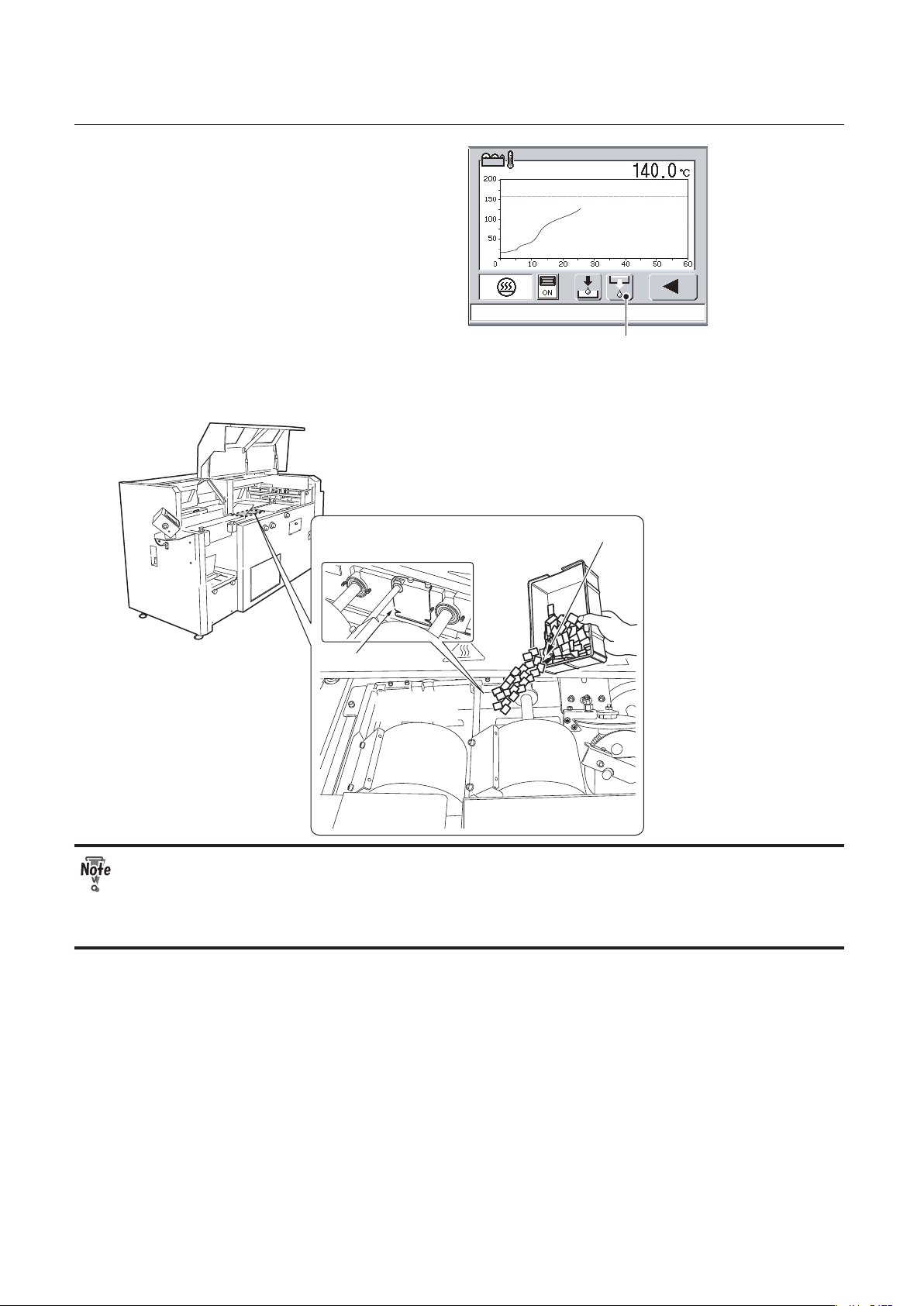
1.
Press the glue tank temperature
button.
The temperature graph will be displayed.
● Check the melt temperature of the hot
glue.
The temperature of the glue tank is set at
150°C/302°F by default. Check the melt
temperature of the hot melt glue you use
and change the glue tank temperature if
necessary.
Chapter 4 "Fine-adjustment and Option
Setting" ”3-4.Setting the Glue Tank
Temperature” ( p.4-18)
20.0
Heater Switch
ON/OFF Button
2.
Press the ON/OFF button of the
heater switch.
Either of the two following icons is
displayed.
OFF ON
The ON/OFF position of the heater
switch will be maintained even after the
machine is turned off. If you turn off the
machine with the heater switch ON, the
heater switch will be ON next time when
you turn on the machine.
Main cover
3.
Open the main cover.
When some hot melt glue is left in the
glue tank.
Go to step 4.
When the glue tank is empty.
Go to step 5.
Page 40
2-4
CHAPTER 2 PREPARING FOR OPERATION
Glue Supply Button
4.
Press the glue supply button.
The side glue rollers will open to the
maximum. If the hot melt glue temperature
has not reached a temperature that is
20°C/68°F lower than the set temperature,
the side glue rollers will not move.
5.
Add hot melt glue in the glue tank.
Add the hot melt glue little by little being careful not to exceed the upper limit.
The upper limit of the hot melt glue
Cutout
Glue tank
Hot melt glue
● When you add hot melt glue, be careful not to put it on the application drums or the
side glue rollers. Make sure that you put it in the glue tank.
● If you added hot melt glue when the glue tank is empty, you need to add the glue
several times until the melted glue reach the upper limit.
Page 41

2-5
CHAPTER 2 PREPARING FOR OPERATION
6.
Close the main cover.
● Be careful not to get your hand caught when you close the main cover.
● When the main cover is open, the heater will be turned OFF automatically. Make sure
that you close the main cover during heating.
Timing for adding glue
● When the message below appears on
the touch panel screen, add hot melt
glue.
Touching the screen will clear the message.
Even after adding hot melt glue, the
icon to the right will blink on the main
menu screen until the glue is melted
completely.
● When the adhesivity of the spine glue
is weak or when the surface of the glue
on the application drums is lumpy, the
remaining amount of the glue may be
low in the glue tank.
● Be careful not to boil dry the glue tank.
● When you add hot melt glue, be careful not to put it on the application drums or the
side glue rollers. Make sure that you put it in the glue tank.
● The temperature around the glue tank is very high. Be careful when you add hot melt
glue.
● High voltage of electricity supplied to the glue tank may cause an electric shock. Be
careful.
Previous Button
7.
Press the previous button to return
to the main menu.
Page 42
2-6
CHAPTER 2 PREPARING FOR OPERATION
3. Preparing Each Section
3-1. Level Plate
To change the milling depth, adjust the height of the level plate. The milling operation jags a spine for
better penetration of the glue. When milling depth is set to 0, a milling function is disabled and only
notches by the roughening blade are applied to the spine, resulting in poor adhesivity.
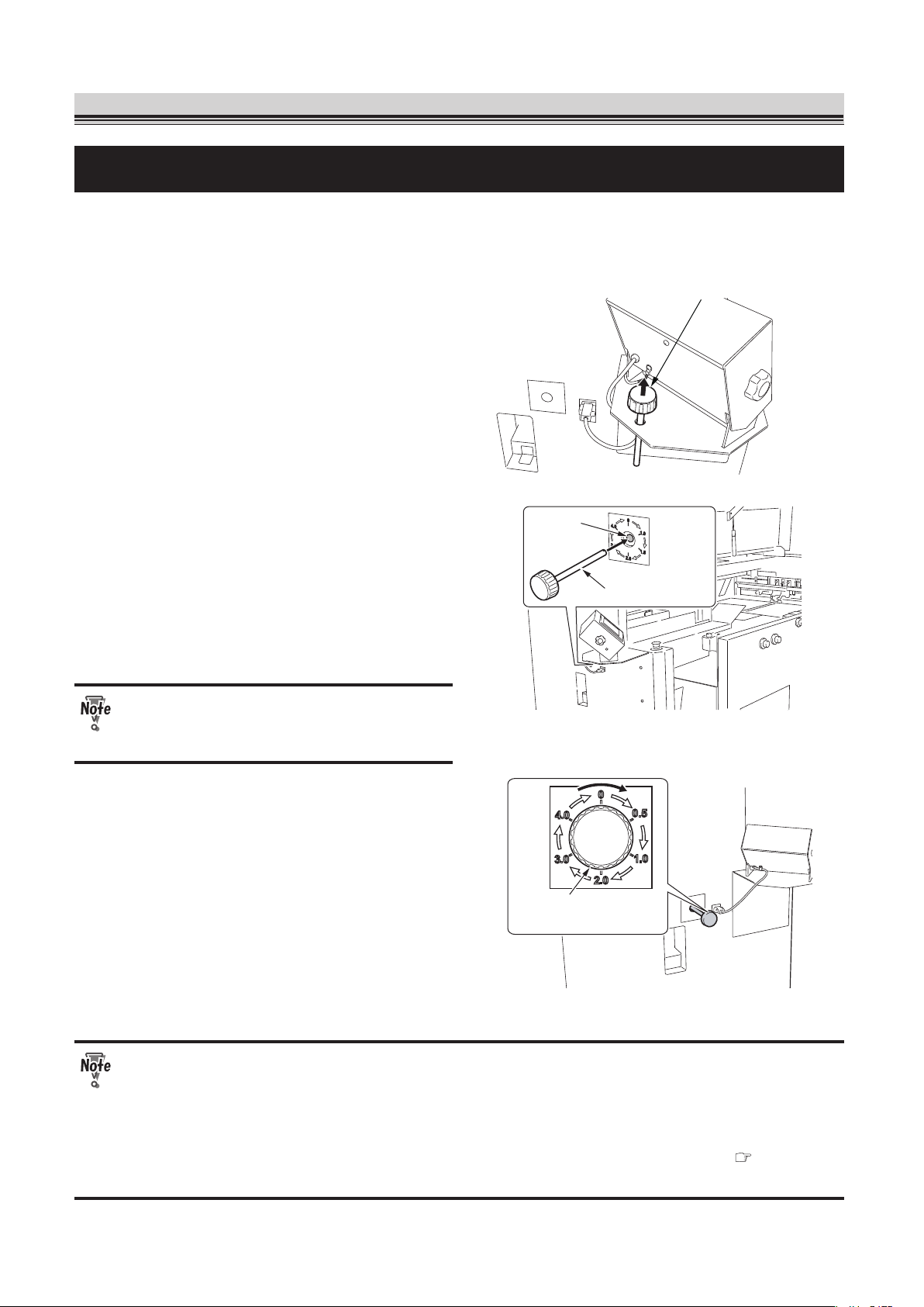
Milling adjustment bar
1.
Pull out the milling adjustment bar
from the machine.
Hole
Milling adjustment bar
2.
Insert the milling adjustment bar to
the hole located on the back of the
touch panel.
After inserting the bar, turn the bar
clockwise until the notch on the tip of the
bar meets the convex part of the hole.
Make sure that you do not insert
anything other than the milling
adjustment bar into the hole.
Milling adjustment
bar
3.
Turn the milling adjustment bar
referring to the label.
You can choose from the six levels: 0, 0.5,
1.0, 2.0, 3.0 or 4.0 mm (0, 0.02, 0.04, 0.08,
0.12, 0.16 inch).
Select a lower level for non-folded paper
and a higher level for folded paper. When
using double-folded paper, select a higher
level than you select for the single-folded
paper.
● When a book block is thick and larger than the A4 size, actual milling depth may be
deeper than the depth you have selected. Do not select a higher level at first.
● Be sure to turn the milling adjustment bar clockwise.
● Do not insert the milling adjustment bar to the hole while the machine is in operation.
● Once you change the milling depth, check the appropriate clamp speed. (
p.4-17)
● Do not turn the milling adjustment bar when a book block is in the clamp.
Page 43

2-7
CHAPTER 2 PREPARING FOR OPERATION
Milling adjustment bar
4.
Pull out the milling adjustment bar
from the hole and put it back to its
original place.
3-2. Glue Tank
The position of the side glue rollers need to be changed depending on whether binding a book block
with a cover or without a cover.
Screw
Wrench
Screw
1.
Loosen the screws (3) using the
supplied wrench (opposite side
distance 3 mm).
Side glue roller
adjustment
Spanner
2.
Turn the side glue roller adjustment
using the supplied spanner to adjust
the position of the side glue rollers.
The iron spanner gets hot. Do not
continue to use it for a long time.
Page 44

2-8
CHAPTER 2 PREPARING FOR OPERATION
Side glue roller
adjustment
A d j u s t a b l e
r a n g e 6 0 °
O p e r a t o r ’ s s i d e
Base position
You can turn the side glue roller adjustment
within the range of 60°.
When binding a book block without a
cover, turn the adjustment 60° to the nonoperator's side from the base position
to move the side glue rollers to the nonoperator's side.
When binding a book block with a cover,
move the adjustment to its base position to
move the side glue rollers to the operator's
side.
If the leading edge of the cover bends,
move the adjustment a bit to the nonoperator's side.
If you turn the adjustment too much to
the non-operator's side when binding a
book block with a cover, side glue may
not be applied to the book block.
3.
Tighten the screws (3) using the
supplied wrench (opposite side
distance 3 mm).
● Before turning the side glue roller adjustment, make sure that the hot melt glue is
completely melted.
● Touching the inside and outside of the glue tank will cause burn injuries.
● Be careful not drop the supplied tools inside the glue tank.
● High voltage of electricity supplied to the glue tank may cause an electric shock. Be
careful.
3-3. Nipping Section
Move the cover stopper to the position for the largest cover size.
Cover stopper
Cover stopper
Cover stopper
adjustment
Cover stopper
adjustment
To a larger size
1.
Loosen the cover stopper
adjustments.
2.
Move the cover stopper to the
position for the largest cover size.
Page 45

2-9
CHAPTER 2 PREPARING FOR OPERATION
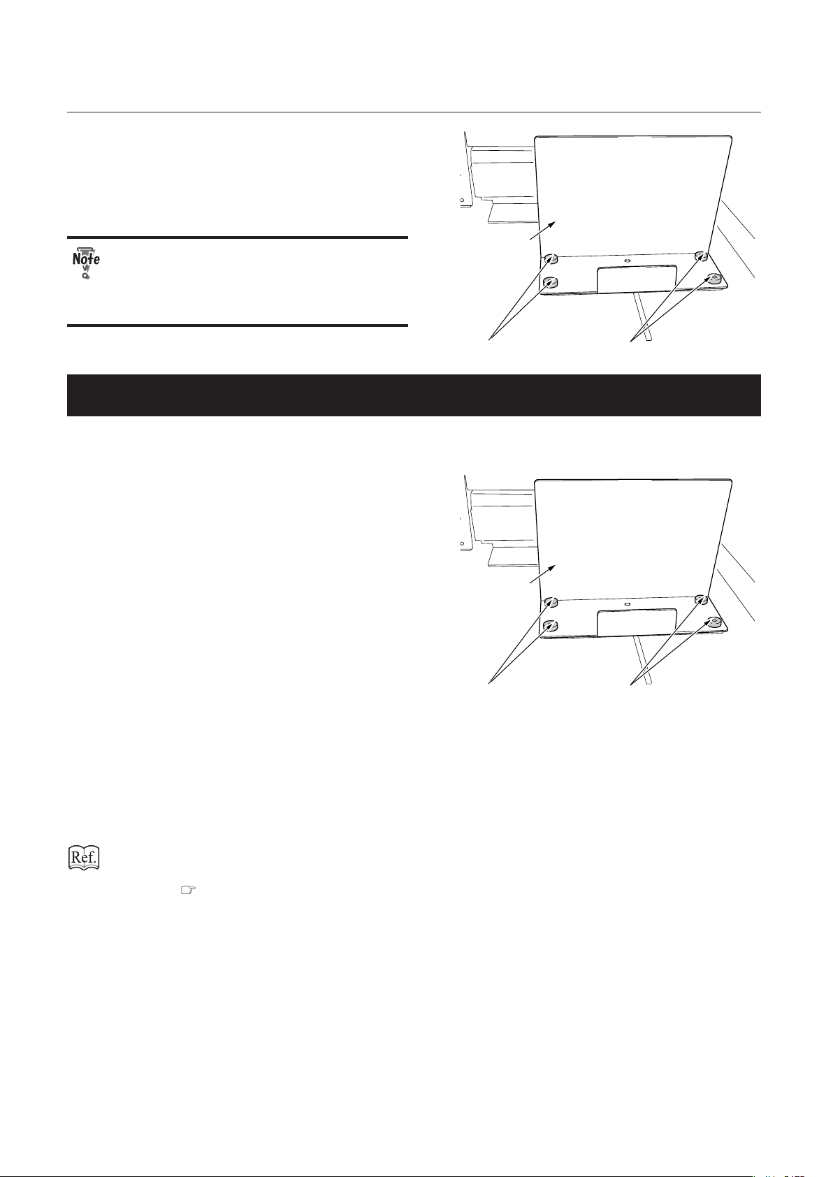
3-4.
Replacing the Receiving Tray with the Stacker Stopper
You can use the stacker stopper for the booklet size of A5, B5, A4 and legal size or for the booklet with
a height of 148 to 216 mm (5.83 to 8.50 inches). To replace the receiving tray with the stacker stopper,
follow the procedures below.
Knob bolt
Receiving
tray
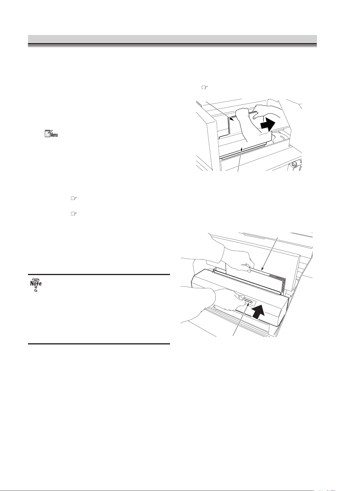
1.
Remove the knob bolts (2) from the
receiving tray.
2.
Raise the receiving tray and pull it
toward you to remove it from the
machine.
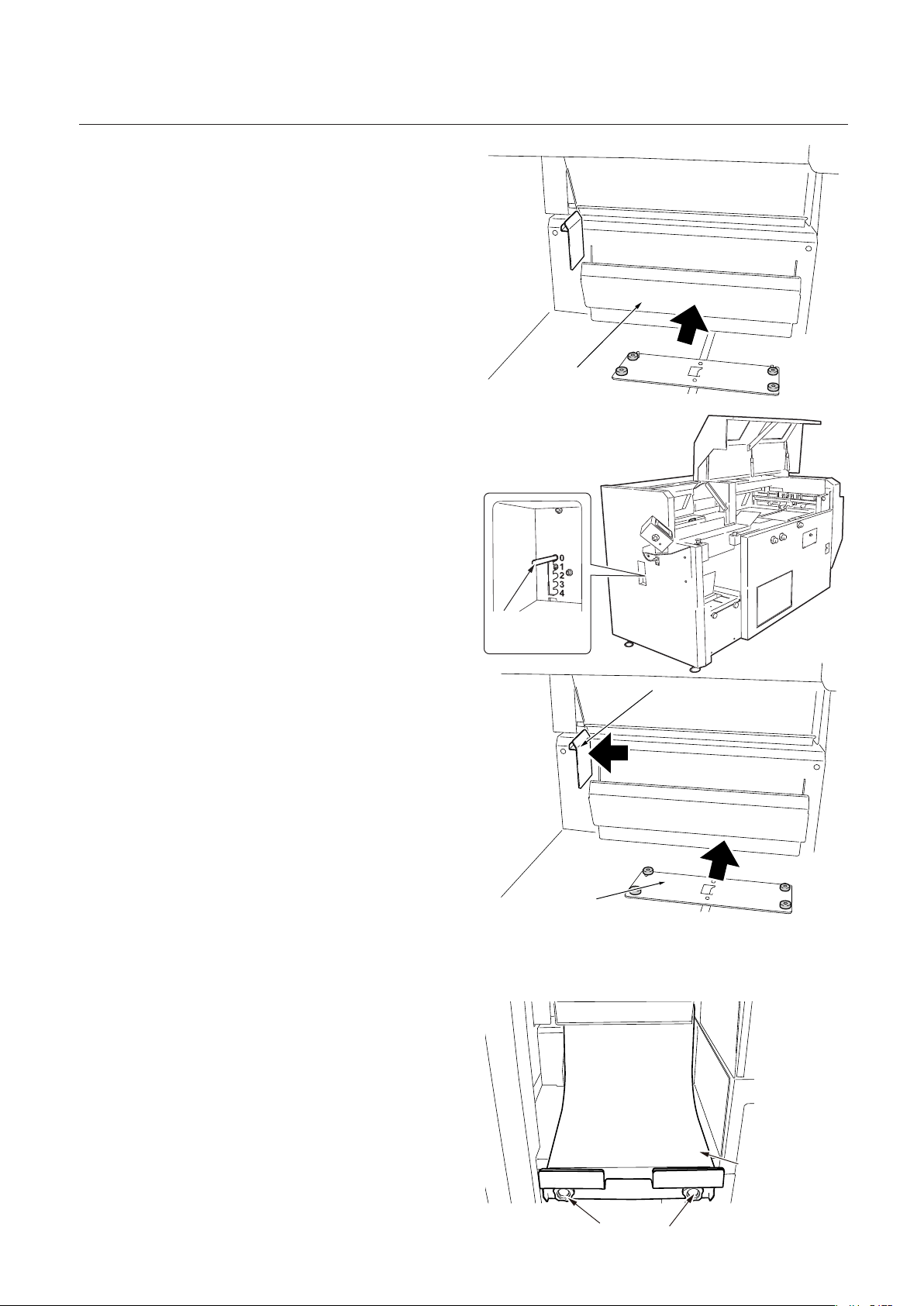
3.
Put back the knob bolts (2) removed
in step 1 to their original places.
4.
Select OFF on the paper receiving
tray ON/OFF setting screen of the
touch panel.
Chapter 4 "Fine-adjustment and Option
Setting" "3-9. Setting the Receiving Tray
ON/OFF" ( p.4-23)
Movable stacker
5.
Check that the movable stacker has
been pushed forward (operator's
side).
Stacker stopper
Stacker stopper base
6.
Place the supplied stacker stopper
on the position as shown in the
figure.
Page 46
2-10
CHAPTER 2 PREPARING FOR OPERATION
Stacker stopper
Knob screw
Knob screw
7.
Secure the stacker stopper to the
machine using the supplied knob
screws (4).
When both a book block and cover is
thin, the booklet may hit the movable
stacker and be curled up. Use the
receiving tray when the booklet is limp.
3-5.
Replacing the Stacker Stopper with the Receiving Tray
If the stacker stopper does not align the discharged booklets, replace the stacker stopper with the
receiving tray.
Stacker stopper
Knob screw
Knob screw
1.
Remove the knob screws (4) from the
stacker stopper.
2.
Remove the stacker stopper.
3.
Put back the know screws (4)
removed in step 1 to their original
places.
4.
Select ON on the paper receiving tray
ON/OFF setting screen of the touch
panel.
The movable stacker will be pushed
backward (non-operator's side).
Chapter 4 "Fine-adjustment and Option
Setting" "3-9. Setting the Receiving Tray
ON/OFF" ( p.4-23)
Page 47
2-11
CHAPTER 2 PREPARING FOR OPERATION
Movable stacker
5.
Check that the movable stacker
has been pushed backward (nonoperator's side).
Book exit
damper
adjustment
6.
Check that the book exit damper
adjustment lever is set to "0."
Stacker stopper base
Stacker side guide
7.
Move the stacker side guide to the
left side.
8.
Move the stacker stopper base to the
non-operator's side by hand.
Knob bolt
Receiving
tray
9.
Place the supplied receiving tray as
shown in the figure and secure it to
the machine using the supplied knob
bolts (2).
Page 48

2-12
CHAPTER 2 PREPARING FOR OPERATION
4. Entering Job Information
Setting
Button
2007-04-05 10:40
You can make the following settings on the
main menu screen.
1. Cover (With a cover/Without a cover)
2. Double feed detection (ON/OFF)
3. Book block size
4. Cover size
5. Cover base position
6. Checking and saving settings for the above
items (1-5)
Press the setting button on the main menu screen to go to the cover (with a cover/without a cover)
setting screen.
4-1. Cover (With a cover/Without a cover)
Select whether binding a book block with a cover or without a cover.
Book block
Cover
Without a Cover
With a Cover
Book block
With a Cover Button
Without a Cover Button
Cover
1.
Select whether to bind a book with or
without a cover.
When you press the button, the color of the
button will change as follows.
Select "With a cover" for binding a book
block with a cover and proceed to the step 3.
Select "Without a cover" for pad binding
and proceed to the step 2.
Page 49

2-13
CHAPTER 2 PREPARING FOR OPERATION
Nipping
ON/OFF
button
Next Button
2.
Select whether to apply nipping to
the book block using the nipping ON/
OFF button.
Nipping (ON) Nipping (OFF)
When nipping is ON, the nipping station will
go up during operation.
Press the next button to go to "4-3. Setting
Book Block Size" ( p.2-16).
Press the cancel button to delete all the
settings you made so far and to go back to
the main menu.
● Before binding without a cover, wipe
the gray-colored part shown in the
figure using a cloth with silicon spray
applied. This will prevent hot melt
glue from adhering to the nipping
surface.
● When nipping is set to ON, short
nipping time may cause glue to
adhere to the nipping station. Check
the open time of the hot melt glue you
use and change the time if necessary
( p.3-15, 4-15).
Cancel Button
Next Button
Double Feed
Detection Button
3.
Turn ON or OFF the double feed
detection.
When set to ON, the double feed detection
button is displayed. Press this button to go
to "4-2. Setting Double Feed Detection for
Cover" ( p.2-14).
When set to OFF, press the next button to
go to "4-3. Setting Book Block Size"
( p.2-16).
Press the cancel button to delete all the
settings you made so far and to go back to
the main menu.
Page 50

2-14
CHAPTER 2 PREPARING FOR OPERATION
4-2. Setting Double Feed Detection for Cover
To make the machine detect double feed, decide and input the detection value. Change the double
feed detection settings when detection error occurs frequently at the default setting (standard value).
1.
Press or to select the LED luminescence amount.
Example
LED
luminescence
amount
“0” will be indicated
as shown above.
255
128
Setting range: AUTO (0) to 255 (standard value: Auto)
When the cover is thin or the print is light: Decrease the value.
When the cover is thick or the print is dark: Increase the value.
2.
Press or to select the double feed detection level.
Using the sensor for measuring paper thickness, the thickness of a cover fed at test feed is read
as the reference data, and is compared with the data of the cover fed at the subsequent feed.
When the difference between those data exceeds the double feed detection level (%) you
specified, the machine determines that a double-feed has occurred.
Setting range: 5 to 100 (standard value: 50)
Example
Double feed
detection level
50
20
75
If the double feed is detected when no double feeds are present: Increase the value.
If the double feed is not detected when double feeds are present: Decrease the value.
Page 51

2-15
CHAPTER 2 PREPARING FOR OPERATION
3.
Press or to select the starting point of the double feed detection.
The starting point is a distance from the leading edge of the cover.
Setting range: 20.0 mm (0.79 inch) to cover length minus 40.0 mm (1.57 inches) (standard
value: 40.0 mm (1.57 inches))
Example
Starting point
of double feed
detection
28.0
24.0
20.0
The double-feed detection sensor is located at 5.0 mm (0.20 inch) down to the operator's side
from the scoring base line.
Spine
Scoring base line
Cover
Double-feed detection sensor
5.0 mm (0.2 inch)
Operator’ s side
Feed direction
Detection errors may frequently occur on a solid black area of the cover. Do not
choose the solid black area as the starting point. Detection error hardly occurs
on a white area or light-color print area.
Previous Button
4.
Press the previous button.
The screen shown in step 3 of "4-1.Cover
(With a cover/Without a cover)"
( p.2-13) will appear.
Next Button
5.
Press the next button.
The screen for "4-3.Setting Book Block Size"
( p.2-16) will appear.
Page 52

2-16
CHAPTER 2 PREPARING FOR OPERATION
4-3. Setting Book Block Size
Select whether to change a book block thickness for each process.
Normal mode
Variable mode
Book blocks Book blocks
Normal: The thickness of book blocks is
same for each process
Variable: The thickness of book blocks
varies for each process.
Next Button
Previous Button
Selector Button
1
. Press the selector button to select
normal or variable.
: Normal
The sensor detects the thickness of the first book block. The same thickness is
applied to the following book blocks.
: Variable
The sensor detects the thickness of the book block each time you feed it.
When the variable mode is selected, the processing speed will slow down.
Next Button
Previous Button
Booklet Length Button
2.
Press the book block length button.
The numeric keypad screen will appear.
If you do not need to change the book
block length, press the next button.
When "With a Cover" is selected
You will go to "4-4. Setting the Cover Size"
( p.2-18).
When "Without a Cover" is selected
You will go to "4-6. Checking and Saving
Settings" ( p.2-21).
Press the previous button to return to the previous screen.
Page 53

2-17
CHAPTER 2 PREPARING FOR OPERATION
Numeric Keypad
Clear Button
Input value
297. 0
3.
Input the book block length using the
numeric keypad.
Setting range: 120 to 360 mm (4.72 to
14.17 inches)
Book block
Book block length
To clear the input value, press the clear button.
Return Button
Cancel Button
297. 0
297. 0
4.
Press the return button to confirm
the value.
Press the cancel button to return to the
previous screen.
Next Button
297. 0
5.
Press the next button.
When "With a Cover" is selected
You will go to "4-4. Setting the Cover Size"
( p.2-18).
When "Without a Cover" is selected
You will go to "4-6. Checking and Saving
Settings" ( p.2-21).
Page 54

2-18
CHAPTER 2 PREPARING FOR OPERATION
4-4. Setting the Cover Size
Next Button
Previous Button
Cover Width Button
Standard Size
Select Button
Cover Length
Button
1.
Press the cover width button for
specifying a cover width and the
cover length button for specifying
the cover length.
The screen to input the value will appear.
If you use a standard-sized cover, press the
standard size select button and proceed to
"Selecting the standard size."
Numeric Keypad
Clear Button
Input value
297. 0
2.
Input the size using the numeric
keypad.
Setting range:
Cover length:
120 to 360 mm (4.72 to 14.17 inch)
Cover width:
250 to 696 mm (9.84 to 27.40 inches)
To clear the input value, press the clear
button.
Return Button
Cancel Button
297. 0
297. 0
3.
Press the return button to confirm
the value.
You will go to "4-5. Cover Base Spine
Position" ( p.2-19).
To delete the input data and return to the
screen shown in step 1, press the cancel
button.
Selecting the standard size
1.
Press the button of a size you use.
When you press the button, its color will
change.
Page 55

2-19
CHAPTER 2 PREPARING FOR OPERATION
Return Button
Cancel Button
2.
Press the return button to confirm
the settings.
You will go to "4-5. Cover Base Spine
Position" ( p.2-19).
To cancel the selection and return to the
screen shown in step 1, press the cancel
button.
4-5. Cover Base Spine Position
There are two types of base spine position: side base and center base.
Book block
Feed guide
Feed guide
Scoring base line
Specified value
Non-operator’ s side
Operator’ s side
Side base (based on a specified value):
If the distance between the scoring position
and cover edge has been decided, use
"side base."
After a size change ( p.3-3), the side
guides will move to align the scoring base
line with the specified base line.
Feed guide
Cover center line
Feed guide
Book block
center line
Non-operator’ s side
Operator’ s side
Center base:
Use "center base" to align the cover center
line with the book block center line.
After a size change ( p.3-3), the side
guides will move to align the cover center
line with the book block center line.
The acceptable cover length for a center
base is 342 to 651 mm (13.46 to 25.63
inches).
Base Spine Position Button
1.
Press the base spine position button.
A value that is equal to half the cover width
will be displayed.
Page 56

2-20
CHAPTER 2 PREPARING FOR OPERATION
2.
For side base
Return Button
Cancel Button
Clear
Button
190. 0
The range you can input
Input the length between the scoring
position and cover edge using the
numeric keypad.
The range you can input will be displayed
on the lower right of the screen. Press the
cancel button or clear button, then input an
appropriate value.
Cover width: 250 to 696 mm/9.84 to 27.40 inches
Specified value:
125 to 325.5 mm/4.92 to 12.82 inches
Cover width – specified value:
125 to 376.5 mm/4.92 to 14.82 inches
Spine
Base Spine Position
Next Button
190. 0
The specified position will align with the
scoring base line.
When you press the next button, you will go
to "4-6. Checking and Saving Settings"
( p.2-21).
Page 57

2-21
CHAPTER 2 PREPARING FOR OPERATION
For center base
0
Return button
Input “0” using the numeric keypad and
press the return button.
Base Spine Position Button
Next Button
The base spine position button will be
displayed as shown in the figure.
The icon means that the scoring base line
will align with the book block center line
when you perform the size change in a later
step.
When you press the next button, you will go
to "4-6.Checking and Saving Settings"
( p.2-21).
When you input a cover length other than 342 to 651 mm (13.46 to 25.63 inches) in
"4-4.Setting the Cover Size," "0" will not be accepted.
4-6. Checking and Saving Settings
You will confirm the settings you made so far for a book block size, cover size, and double feed
detection and save them to a memory.
1.
Check the settings of before and
after changing.
Book block length
Cover (With a cover,
Without a cover
Cover width
Cover length
Base spine position
LED luminescence amount
Double feed detection level
Starting point of the double
feed detection
Book block thickness (variable/normal)
Before Change
Before Change
After Change
After Change
Page 58

2-22
CHAPTER 2 PREPARING FOR OPERATION
Memory No.
Cancel Button
Previous Button
2.
Press or to select the
destination to save the settings.
The number of memories is 20 and all of
them contains the same setting data by
default.
Book block length: 297.0 mm (11.69 inches)
Book block thickness: variable
Cover (with or without a cover): With a cover
Book block width: 420.0 mm (16.54 inches)
Cover length: 297.0 mm (11.69 inches)
Base spine position: 210.0 mm (8.27 inches)
LED luminescence amount: 0 (Auto)
Double feed detection level: 50%
Starting point of the double feed detection: 40.0 mm (1.57 inches)
When you press the cancel button, the
setting data will be deleted and you will
return to the main menu.
To return to previous screen, press the
previous button.
Memory Button
3.
Press the memory button for more
than one second.
The message “Do you want to clear the fine
adjustment data?” will appear. Press "Yes"
if you want to clear the data.
When you press "Yes," the fine-adjustment
data you set in the past will be erased.
You will return to the main menu.
Page 59

Chapter 3
STARTING BINDING
OPERATION
Page 60
3-2
CHAPTER 3 STARTING BINDING OPERATION
1. Placing a Book Block
When binding with a cover:
Follow the procedures below.
When binding without a cover:
After completing the step 2, go to "3. Starting Binding" ( p.3-14).
Clamp Section
Book block
1.
Place the book block in the clamp.
Be sure to press the book block against the
right edge of the clamp.
When the book block is lower than the
support clamp and it is difficult to press
the book block against the right edge,
adjust the opening amount of the clamp
referring to Chapter 4 "Fine-adjustment
and Option Setting" "3-13.Setting
Opening Amount of Clamp (for Normal
Mode)" ( p.4-27) and "3-14.Setting
Opening Amount of Clamp (for Variable
Mode)" ( p.4-28).
Book block
Support clamp
2.
While holding the book block, press
the support clamp against the book
block with your other hand.
● Be sure to use the support clamp.
The support clamp will prevent a limp
book block from bending over in the
clamp.
● When the book block is small, be
careful not to get your hand caught
between the support clamp and book
block.
Page 61
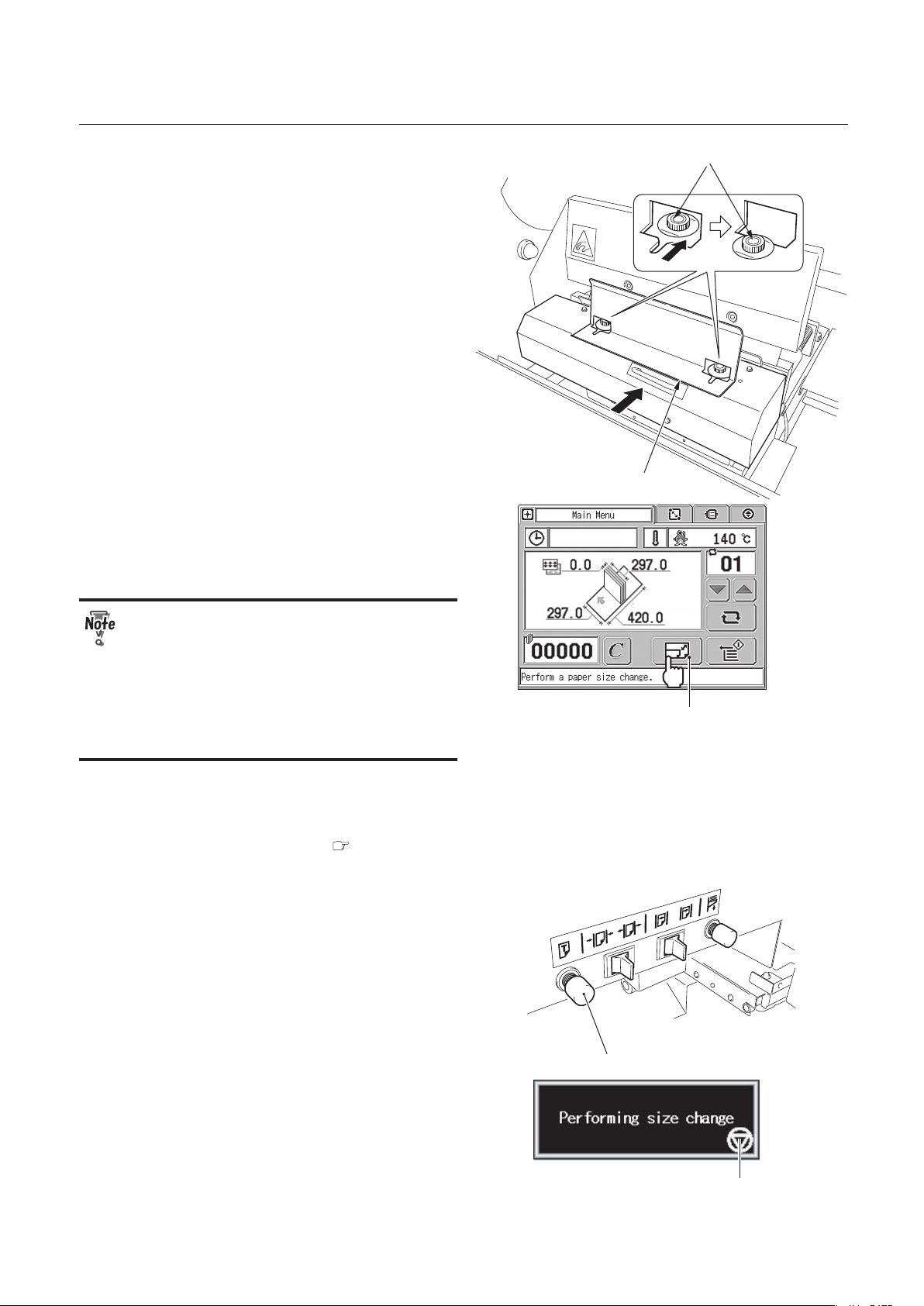
3-3
CHAPTER 3 STARTING BINDING OPERATION
Clamp guide
Screw
When the book block is thin and large:
When the book block is thin and large,
attach the supplied clamp guide to prevent
the book block from bending over. Secure
the clamp guide to the clamp using the
screws attached to the clamp.
Size Change Button
2007-04-05 10:50
3.
Press the size change button on the
main menu.
When there is a cover on the paper
feed tray or nipping station, you cannot
perform a size change. From the second
size change, however, you can perform
a size change with a cover on the paper
feed tray if the cover size is the same as
the one used for the first size change.
If you want to bind a book block without a
cover, a size change is unnecessary.
Go to "3. Starting Binding" ( p.3-14).
Test feed button
You can also perform a size change using
the test feed button located above the
paper feed tray.
Size Change Cancel Button
During execution of the size change, the
message shown to the right is displayed on
the touch panel screen.
Each unit will start moving. Wait until the
message disappears.
Page 62

3-4
CHAPTER 3 STARTING BINDING OPERATION
To cancel the size change, press the size
change cancel button.
The test feed button above the paper
feed tray has a test feed function.
Movable clamp button
If you press this button when the
movable clamp button icon is displayed
on the main menu screen, a test feed
will start.
Size change button
Before pressing the test feed button,
make sure that the size change button
icon is displayed on the main menu.
2007-04-05 10:50
When the size change is complete, the
original screen will appear.
When there is no covers on the paper feed
tray, the message to the right will appear.
You can clear the message by touching the
message screen or placing a cover on the
paper feed tray.
When the book block thickness is less than
3 mm, the message to the right will appear.
You can clear the message by touching
the message screen. Move the axes of the
scoring depth adjustments in the upright
position for a book block with a thickness of
less than 3 mm.
Even if the thickness of the book block
is 3 mm or more, if you have adjusted
the scoring width in the minus direction
in Section 4 “1-2. Setting the Scoring
Width” ( p.4-4), the width may become
less than 3 mm. In that case, the
message to the right will appear.
Page 63
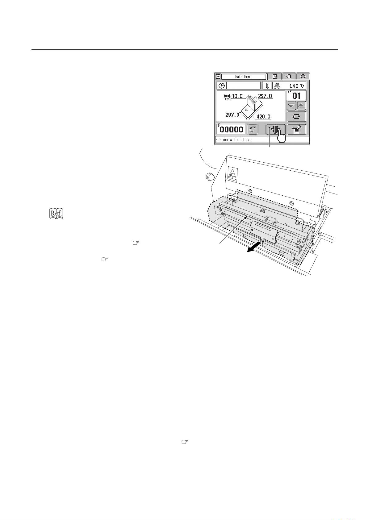
3-5
CHAPTER 3 STARTING BINDING OPERATION
Taking out the book block set in the clamp after size change
Movable Clamp Button
2007-04-05 10:50
After a size change, you cannot take out
the book block from the clamp because
it is firmly held in the clamp. To take out
the book block, press the movable clamp
button on the main menu.
Movable clamp
The movable clamp will move to the
position specified on the option screen.
When set to normal mode:
book block thickness + specified value
When set to variable mode: specified value
Chapter 4 "Fine-adjustment and Option
Setting" "3-13.Setting Opening Amount of
Clamp (for Normal Mode)" ( p.4-27) and
"3-14.Setting Opening Amount of Clamp (for
Variable Mode)" ( p.4-28)
After taking out the book block, follow the
procedures below according to the size and
thickness of the book block you are going
to place in the clamp.
● When the length and size of the book
block is same as the one you took
out:
Follow the steps 1 and 2. Skip the step 3.
● When the book block size is same,
but the thickness is different:
Press the movable clamp button again to
return it to its original position and follow
the steps 1 to 3.
● When the book block size and
thickness are different:
Go back to "4.Entering Job Information" ( p.2-12).
Page 64
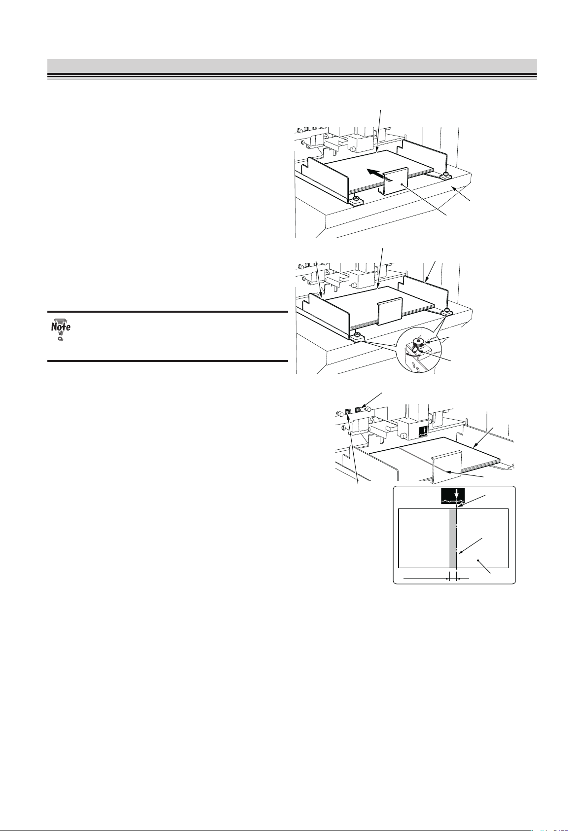
3-6
CHAPTER 3 STARTING BINDING OPERATION
2. Test-Feeding a Cover
Paper feed tray
Cover
Back stopper
1.
Load covers on the paper feed tray
and press the back stopper against
the covers.
Cover feeder
skewing adjustment
Axis
Feed guide Feed guide
Cover
2.
Loosen the cover feeder skewing
adjustments and turn the axes until
the feed guides align with the covers.
Do not press the feed guides hard
against the covers. This may cause misfeed.
Red beam
Cover
Red beam
Cover
Spine width
Guide adjustment
switch A
Guide adjustment
switch B
Scoring line
3.
(For a side base) Move the covers
until the spine base line aligns
with the red beam, using the guide
adjustment switches A or B.
Moving the guide adjustment switch A to the
left will move the paper feed guides closer
to each other. Moving the guide adjustment
switch A to the right will move the paper
feed guides farther from each other.
Moving the guide adjustment switch B to
the left will move the paper feed guides
to the operator's side. Moving the guide
adjustment switch B to the right will move
the paper feed guides to the non-operator's
side.
The increment of the guide adjustment
switches A and B varies depending on how
long you keep pressing the switch.
Press the switch:
0.1 mm (0.004 inch)
Keep pressing the switch:
1.0 mm (0.04 inch)
When you continue to press the switch, the
paper feed guides will keep moving by 1.0
mm (0.04 inch).
Page 65

3-7
CHAPTER 3 STARTING BINDING OPERATION
When selecting a center base, check
the position of the cover attached to the
book block, then fine adjust each part.
You can also make the adjustments
using the fine-adjustment screen. Refer
to Chapter 4 "Fine-adjustment and
Option Setting" "1-1. Setting the Paper
Feed Guide" ( p.4-2) for details.
Cover
Stack height
sensor adjustment
4.
Turn the stack height sensor
adjustment.
The base position is “2.” When a thick cover
is not sent to the nipping section, set it to “1.”
Separating air
adjustment
Cover
5.
Turn the separating air adjustment
to adjust air volume sent to between
each cover.
The base position is “4.”
When you feed a small cover, turn the
adjustment to the direction of 1.
When you feed a thick cover, turn the
adjustment to the direction of 7.
Turn the adjustment little by little checking
the feeding conditions.
Cover
Separator
Adjustment
Separator
adjustment
Separator
Suction belt
Gap between
separator and
suction belt
6.
Turn the separator adjustment to
adjust the gap between the separator
and suction belt.
The base position is “3.”
When a double feed occurs, turn the
adjustment to the direction of 1. The gap
between the separator and suction belt will
be narrower.
When a mis-feed occurs, turn the
adjustment to the direction of 5. The gap
between the separator and suction belt will
be wider.
Page 66

3-8
CHAPTER 3 STARTING BINDING OPERATION
Turn the adjustment little by little checking
the feeding conditions.
Test feed button
7.
Press the test feed button to feed a
cover.
The cover will be sent to the nipping
section.
Make sure that you move the cover
stopper to the position for the largest
paper size before you press the test feed
button. ( p.2-8)
Test Feed Button
2007-04-05 11:00
You can also feed the cover by pressing the
test feed button on the main menu screen.
● When the cover size is small and is
not smoothly fed into the nipping
section, use the supplied parts
( p.3-23).
● You can feed the cover even when the
main cover is open.
8.
Check that double-feed has not
occurred.
During test feeding, even though a doublefeed occurs, an error message "E-022
Double feed" will not appear on the LCD
monitor.
When a double-feed has occurred, remove
the cover from the nipping station and go
back to the step 5.
● If you feed the cover when the main cover is open, make sure that there is no one
around the feed section and nipping section.
● Do not put your hand inside the machine while the paper feed tray is moving. This may
cause unexpected injuries.
Page 67

3-9
CHAPTER 3 STARTING BINDING OPERATION
Scoring depth adjustment
Primary feed roller
pressure adjustment
Secondary feed roller
pressure adjustment
9.
Check the scoring condition.
Base position
Scoring becomes deeper
axis
axis
axis
Knob
Knob
Scoring depth adjustment
To adjust the scoring depth, loosen the
knob on the right and left scoring depth
adjustments and turn each axis to the right.
When the axes are in the upright position,
no scoring will be applied.
Depending on the condition, you may need
to adjust only one axis. Turn the axis little
by little by checking the scoring condition.
● If the axis positions on both sides
are very different from each other, a
cover may be torn or skewed.
● If the thickness is less than 3 mm,
move the axes of the scoring depth
adjustments in the upright position
because a score cannot be applied to
that thickness.
Page 68

3-10
CHAPTER 3 STARTING BINDING OPERATION
Adjustment
Base position
When the cover is skewed.
Primary feed roller pressure
adjustment
Leave the adjustment in its original position
in normal times. However when the
cover is skewed, move the position of the
adjustment.
The higher the position is, the stronger the
pressure is.
The right and left adjustments should be in
the same position.
However, there are times when adjusting
either pressure can correct the skew.
If you increase the pressure for a thin
cover, the cover may get creases. Adjust
the pressure checking the feeding
conditions.
Base position When the cover is
not smoothly fed.
Secondary feed
Secondary feed roller pressure
adjustment
Leave the adjustment in its original position
in normal times. However when the cover is
not fed smoothly, lower the secondary feed
roller pressure adjustment to increase the
pressure.
● Use a cover with the thickness of 157g/m² or more to apply a score to the cover.
● When the cover thickness is less than 157g/m², a score may be skewed. Also, a print
near the folding line may have cracks if the nipping is applied without scoring.
● The paper's grain direction comes in two types: the long grain and the short grain. The
applied scoring condition will change according to the paper's grain direction.
Grain direction
Feed direction
When using the short grain paper:
Because the scoring direction (feed
direction) is same as the grain, a
score will be applied to the short
grain paper more easily than to the
long grain paper. A thin cover may be
partly torn.
Grain direction
Feed direction
When using the long grain paper:
Because the scoring direction (feed
direction) meets the grain at a right
angle, a score will not be applied to
the long grain paper as easily as to
the short grain paper.
Page 69

3-11
CHAPTER 3 STARTING BINDING OPERATION
Nipper guide adjustment
Nipper guide adjustment
Nipper guide
Leading edge of the cover
Positioning finger
Positioning finger adjustment
Cover
stopper
Cover
stopper
Nipper
guide
Knob screw
Knob
screw
10
. Press the tail edge of the cover
against the positioning fingers, then
move the cover stoppers to the
leading edge of the cover.
11
. Align the cover with the book block
using the nipper guide adjustments.
Before turning the nipper guide
adjustment, loosen the knob screw.
Guide line
Nipper guide adjustment
Center line
Knob screw
Turn the nipper guide adjustment so that
the guide line aligns with the center line on
the label.
Base position
Moved to the left
Positioning
fingers adjustment
Positioning
fingers adjustment
Adjustable range 4 mm (0.16 inch)
After adjusting the nipper guide, if the
positioning fingers are away from the tail
edge of the cover, turn the positioning finger
adjustment to move the positioning fingers.
Turning the positioning fingers adjustment
to the operator's side (downward) will move
the positioning finger to the left and turning
it to the non-operator's side (upward) will
move the positioning finger to the right (base
position) within a range of 0 to 4 mm (0.16
inch).
Page 70

3-12
CHAPTER 3 STARTING BINDING OPERATION
Nipper base line
Scoring base line
Match these lines.
Nipper
(operator
’
s side)
Cover
Cover
Spine
Nipper
(non-operator
’
s side)
12
. Adjust the position of the nipper
guides on the touch panel screen so
that the nipper base line of the nipper
(non-operator's side) is parallel to
the scoring base line.
Do not touch the nipping section while
the machine is in operation. Your fingers
may get caught in the nipper.
You can fine adjust the scoring width
with the main cover open. After
completing the fine-adjustment, make
sure that you close the cover.
Fine-adjustment tab
1) Press the fine-adjustment tab on the
main menu.
Nipping Guide
Select Button
2) Press the nipper guide select button.
The screen for adjusting the nipper guide
will appear and the nipping station will
go up. If you have not performed a size
change, the screen will not appear.
3) Press the move buttons 1 to 4 to adjust the positions of the nipper guide (front) and
nipper guide (back).
Fine-adjustment range: ±25.0 mm (0.98 inch)
Move button 1: The nipper guides (front, back) move to the non-operator’s side.
Move button 2: The nipper guides (front, back) move to the operator’s side.
Move button 3: The nipper guides (front, back) move closer to each other.
Move button 4: The nipper guides (front, back) move farther from each other.
Increment change button:
You can select the increment from 0.1 mm/0.5 mm/1.0 mm (0.004 inch/0.02 inch/0.04 inch).
: 0.1 mm (0.004 inch)
: 0.5 mm (0.02 inch)
: 1.0 mm (0.04 inch)
Page 71

3-13
CHAPTER 3 STARTING BINDING OPERATION
Increment Change Button
Nipping Guide (back) Fine-adjustment
Nipping Guide (front) Fine-adjustment
Previous Button
Move Button 1 Move Button 5
Move Button 6
Move Button 3
Move Button 2
Move Button 4
Positioning Fingers
Fine-adjustment
You can fine adjust the paper feed guides using the guide adjustment switches above the paper
feed tray when there is a cover on the nipping station.
Chapter 4 "Fine-adjustment and Option Setting" "1-3. Adjusting the Nipper Guide" ( p.4-5)
4) Press the move button 5 or 6 to adjust the position of the positioning fingers.
Fine-adjustment range: 0 to 25.0 mm (0 to 0.10 inch)
Move button 5: The positioning fingers move to the left.
Move button 6: The positioning fingers move to the right.
The increment you selected in step 3) will be automatically applied to the positioning fingers.
To change the increment, press the increment change button and select the increment from
0.1 mm/0.5 mm/1.0 mm (0.004 inch/0.02 inch/0.04 inch).
You can also adjust the positioning fingers by turning the positioning finger adjustments in the
range of 0 to 4 mm (0 to 0.16 inch) ( p.3-11).
5) Press the return button.
The nipping station will go down.
Page 72

3-14
CHAPTER 3 STARTING BINDING OPERATION
3. Starting Binding
Safety sensor
Safety sensor
Lamp
Clamp
1.
Check that the lamp blinks or lights
up and place a book block in the
clamp.
When the lamp blinks or lights up, you
can place a book block in the clamp. If
you interrupt the light between the safety
sensors when the lamp is off, the machine
stops for safety. In that case, refer to "When
Binding Operations are Interrupted"
( p.3-16).
When the book block you placed in
"1.Placing a Book Block" ( p.3-2) is still in
the clamp, proceed to the step 2.
Book block
Start button
2.
Check that the lamp lights up and
press the start button.
Although you can place the book
block in the clamp when the lamp is
blinking, binding will not start even if
you press the start button. If the lamp
blinks because a cover has not been
transported to the nipping section from
the paper feed tray or the heater is still
heating up, the lamp will light up when
the machine is ready. If the lamp blinks
because of other reasons, follow an
error message displayed on the screen.
When binding with a cover
Only for the first set of book block, the
caution message and the nipping delay
time setting screen appear.
Nipping Delay
Time
.
Page 73

3-15
CHAPTER 3 STARTING BINDING OPERATION
When nipping is set to ON, if the nipping time is short, the booklet may be discharged before the
applied glue is dry and the glue may be adhered to the level plate. Check the open time of the
hot melt glue you use and change the time if necessary.
Press or to change the nipping delay time.
Default setting: 0.0 sec.
Setting range: 0.0 to 30.0 sec.
When binding without a cover
Only for the first set of book block, if the nipping delay time is set to 6.5 sec. or more, the
caution message and the nipping delay time setting screen appear.
Check the open time of the hot melt glue you use and change the time if necessary.
Regardless of the nipping delay time settings, the message does not appear from a
second set of book block. Go to step 4.
3.
Press the start button again.
The lamp goes off and the machine starts binding the book block.
4.
Check the quality of the discharged
booklet.
If you need any adjustment, refer to Chapter 4 "Fine-adjustment and Option Setting" “1. Fine
adjusting Each Part" ( p.4-2).
When you use the receiving tray, take out the booklet each time it is discharged.
5.
Repeat the steps 1, 2 and 4.
When the cover thickness is set to "normal," the cover for the next book block will
be fed into the nipper automatically and scores will be applied to it. If you place more
covers on the paper feed tray than necessary, the covers will be continually fed even
after you have finished binding for the last book block.
You can start binding without pressing the start button by using the auto start
function. Once you place a book block in the clamp, the machine will start binding
operations automatically. Refer to Chapter 4 "Fine-adjustment and Option Setting"
"3-7. Setting the Auto Start ON/OFF" (
p.4-21) for details on how to set the auto start
function.
Page 74

3-16
CHAPTER 3 STARTING BINDING OPERATION
When Binding Operations are Interrupted
If you interrupt the light between the safety sensors during binding operations (when the lamp is off),
the operations will stop. When you remove your hand from the sensor area, the following messages
are displayed alternately.
When the clamp has returned to the level plate, messages are displayed depending on the situation.
When interrupted after a cover is applied to a book block
Paper ejection button
1) Check that the spine glue is not hot and press the paper ejection button on the touch
panel screen.
A booklet will be ejected to the stacker.
2) Remove the booklet from the stacker.
3) Check the quality of the booklet.
Spine glue is very hot. Before you remove the booklet, make sure that it is not hot.
When interrupted before a cover is applied to a book block
Movable clamp button
1) Check that the spine glue is not hot and press the movable clamp button on the touch
panel screen.
The movable clamp will open.
2) Remove the booklet from the clamp.
3) Place a new book block in the clamp.
● Spine glue is very hot. Before you remove the booklet, make sure that it is not hot.
● Because parts of binding processes have already been applied to the book block in
the clamp, if you try to continue the operation using that book block, the finished
booklet will have poor quality. Replace a book block in the clamp with a new one.
Page 75

3-17
CHAPTER 3 STARTING BINDING OPERATION
4. Removing the Booklet
When biniding operations are complete, a finished booklet with a cover will be discharged
automatically to the stacker. Remove the booklet from the stacker following the procedures below. For
a booklet without a cover, take it out from the clamp yourself.
Do not take out a booklet while the machine is in operation. It may cause unexpected
injuries.
Stacker stopper
1.
Pull the stacker stopper to your side.
Finished booklet
2.
Remove the finished booklet from
the machine.
Stacker stopper
3.
Push back the stacker stopper all the
way in.
Page 76

3-18
CHAPTER 3 STARTING BINDING OPERATION
When the booklet is not discharged smoothly
Booklet
If the book block is thin and the cover
is thick, the finished booklet may not be
discharged smoothly. In that case, push the
booklet downward with your hand.
When the stacker is full of booklets
When the stacker is full of booklets during
operation, the caution message to the right
is displayed. To take out the booklets, follow
the steps 1 through 3 of the previous page.
After pushing back the stacker stopper
all the way in in step 3, the message will
disappear.
When the booklets do not align in the stacker
Stacker side guide
Booklet
20 mm (0.79 inch)
When a booklet bounces laterally in the
stacker section, use the stacker side guide.
The appropriate position for the stacker
side guide is 20 mm (0.79 inch) away from
the left edge of the booklet.
● If you position the stacker side guide too closely to the booklet, a discharged booklet
may hit the stacker side guide, resulting in damage on the booklet.
● Every time you change a book block size, adjust the position of the stacker side guide.
Otherwise a discharged booklet may hit the stacker side guide, resulting in damage on
the booklet.
● Keep the stacker side guide to the left when not in use.
Page 77
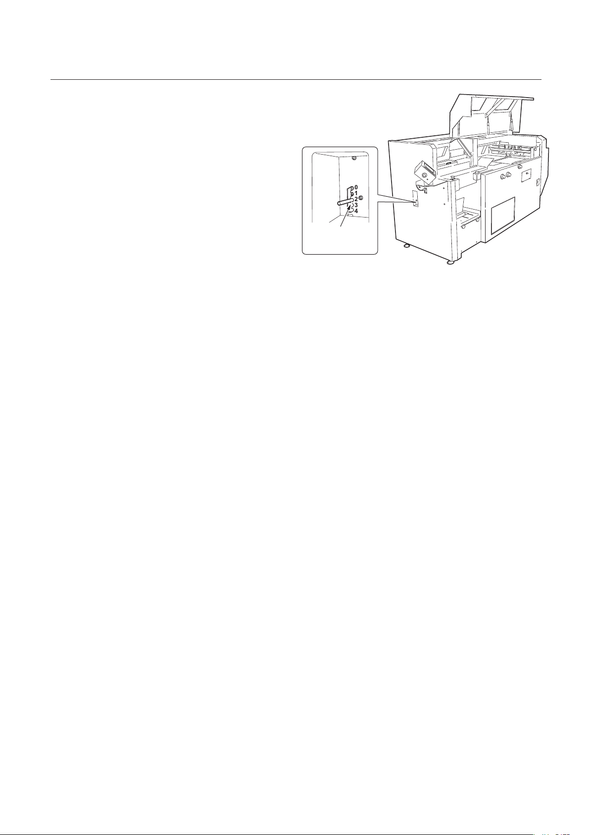
3-19
CHAPTER 3 STARTING BINDING OPERATION
Book exit damper
adjustment lever
Depending on the types of a booklet, when
impact absorption at the book exit damper
is low, the booklets may not align.
Adjust the book exit damper adjustment
lever according to the weight (thickness) of
the booklet.
Base position: 0
"4" has the highest absorption. Move the
lever toward "0" when the booklet is light
and toward "4" when it is heavy. When the
booklet thickness is 2 mm (0.08 inch) or
thinner, set it to "1."
Page 78

3-20
CHAPTER 3 STARTING BINDING OPERATION
5. Adding Covers
Before you add covers to the paper feed tray, make sure that the lamp lights up or blinks. When the
lamp is off, the machine is in operation.
Lamp
Feed guide
Feed guide
Cover
Back stopper
1.
Pull the back stopper to your side.
Feed tray down switch
2.
Press the feed tray down switch.
Only while you are pressing the feed tray
down switch, the paper feed tray goes
down.
When there is no paper on the paper feed
tray, it will automatically go down.
Feed guide
Feed guide
Cover
Back stopper
3.
Load covers on the paper feed tray
and press the back stopper against
the tail edge of the covers.
Page 79
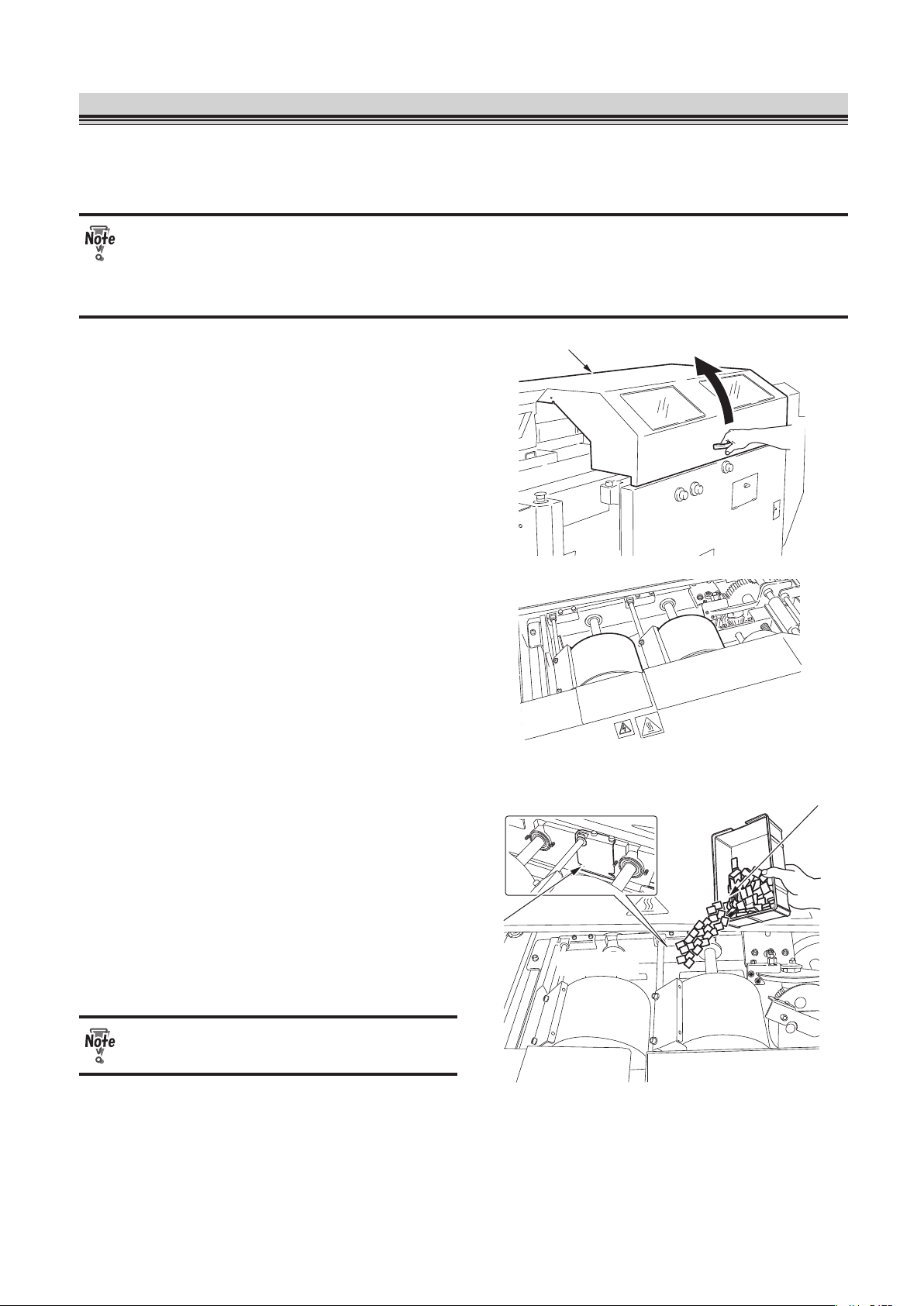
3-21
CHAPTER 3 STARTING BINDING OPERATION
6. Finishing Binding
Once a binding operation is complete, check if there is enough hot melt glue left in the glue tank. If the
surface of the glue on the application drums is lumpy, you need to add hot melt glue to the glue tank.
Be careful not to boil dry the glue tank.
● High voltage of electricity supplied to the glue tank may cause an electric shock. Be
careful.
● The temperature around the glue tank is very high. Be careful when you add hot melt
glue.
Main cover
1.
Open the main cover.
2.
Check the remaining amount of the
hot melt glue.
Hot melt
The groove is the upper limit
for hot melt
Groove
Glue tank
3.
Add hot melt glue to the glue tank if
necessary.
4.
Close the main cover.
Be careful not to get your hand caught
when you close the main cover.
Page 80

3-22
CHAPTER 3 STARTING BINDING OPERATION
Power switch
5.
Turn the power switch in the
direction shown in the figure to turn
off the power of the machine.
Page 81

3-23
CHAPTER 3 STARTING BINDING OPERATION
7. Using Supplied Parts
When a cover on the paper feed tray is small, it may not be smoothly fed into the machine and a feed
error may occur. In that case, use the supplied parts.
When feeding small-sized paper (170 mm (6.69 inches) long or less)
● Turn down the separating air volume by turning the separating air adjustment to the
direction of 1 ( p.3-7).
● Increase the separating pressure by turning the separator adjustment to the direction
of 1 ( p.3-7).
Scoring label
Stabilizer plate lite weight cover
Attachment level
Stabilizer plate lite weight cover
When separating air causes the tail edge of
the cover to flip, attach the magnet surface
of the stabilizer plate lite weight cover on
the scoring label.
Align the upper edge of the stabilizer plate
lite weight cover with the attachment level
shown in the figure.
Small cover feed belt accessory
Stack height sensor adjustment
Small cover feed belt accessory
(For a cover with the length of 140 mm (5.51
inches) or less)
When covers are fed into the machine in
series, screw this to the back of the stack
height sensor adjustment.
Do not use the small cover feed belt
accessory for paper weighing 157g/m²
or more.
Screw head
Lever
Small cover guide
Small cover guide
(For a cover with the length of 140 mm (5.51
inches) or less)
The small cover guide prevents a cover
from touching the lever of the stack height
sensor.
Attach the hole on the magnet surface of
the small cover guide to the screw head,
which is located next to the scoring line
label.
Page 82
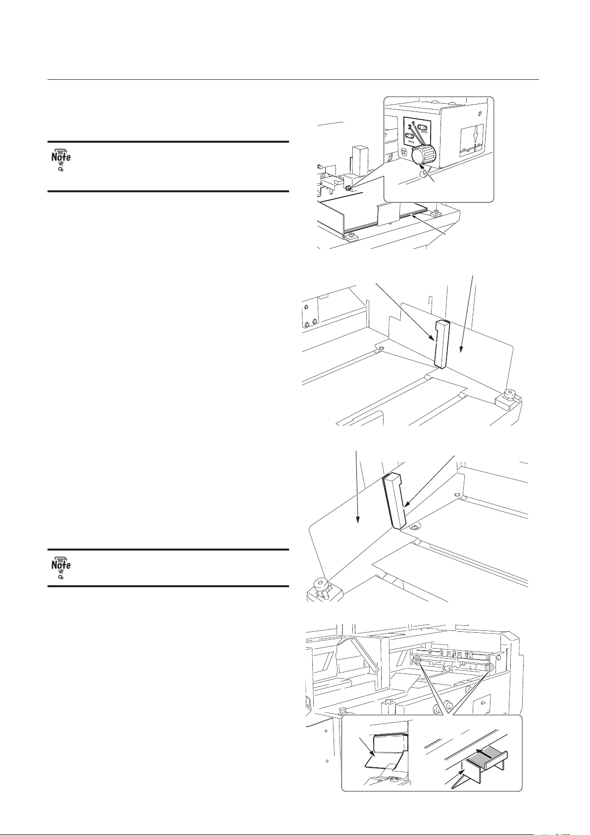
3-24
CHAPTER 3 STARTING BINDING OPERATION
Cover
Stack height
sensor adjustment
Set the stack height sensor adjustment to
"2."
Do not use the small cover feed belt
accessory for paper weighing 157g/m²
or more.
Small cover guide (R)
Paper feed guide (back)
Small cover guide (R)
(For a cover with the length of 170 mm (6.69
inches) or less)
The small cover guide holds down the tail
edge of a cover. Attach the magnet surface
of the small cover guide (R) to the paper
guide (back).
Small cover guide (L)
Paper feed guide (front)
Small cover guide (L)
(For a cover with the length of 170 mm (6.69
inches) or less)
The small cover guide holds down the tail
edge of a cover. Attach the magnet surface
of the small cover guide (L) to the paper
guide (front).
Do not load paper as high as 41 mm (1.61
inches) or more.
Press the guide firmly
to the machine.
Guide
Guide
Guide
When a cover does not fit into the nipper
guides because of its curled edge, attach
the magnet surface of each guide to the
either side of the scoring section.
Page 83

3-25
CHAPTER 3 STARTING BINDING OPERATION
8. Using Wing Scoring
When you want to turn-in a cover, use the wing scoring (optional) to apply a score to a position to be
folded. The range you can apply a score is between 120 to 189 mm (4.72 to 7.44 inches) above the
scoring base line on the non-operator's side and between 160 to 199 mm (6.30 to 7.83 inches) below
the scoring base line on the operator's side.
As the wing scorings are located on the operator's side and non-operator's side, first adjust the wing
scoring on the operator's side, then that on the non-operator's side.
Operator’s side
Non-operator’s side
Scoring base line
Adjustable range
189 mm (7.44 inches)
Adjustable range
199 mm (7.83 inches)
Book block maximum thickness
51 mm (2.01 inches)
120 mm
(4.72 inches)
160 mm (6.3 inches)
Feed direction
Knob screw
1.
Loosen the knob screw (1) of the
upper wing scoring one or two turns
by hand.
Shaft
Jam removing knob
Fixing screw
2.
Turn the jam removing knob to make
the fixing screw (1) of the lower wing
scoring shaft face upward.
Page 84

3-26
CHAPTER 3 STARTING BINDING OPERATION
Fixing screw
Wrench
3.
Loosen the fixing screw (1) of the
lower scoring roller by turning it
counterclockwise using the supplied
wrench (opposite side distance 2
mm).
Lower scoring roller
4.
Move the lower scoring roller to the
desired position for scoring.
5.
Fasten the fixing screw (1) of the
lower scoring roller by turning it
clockwise using the supplied wrench
(opposite side distance 2 mm).
Scoring depth adjustment
Knob
6.
Loosen the knob of the upper
scoring roller and put the scoring
depth adjustment in the upright
position.
Lower scoring roller
Upper scoring roller
7.
Move the upper scoring roller to the
same position as the lower scoring
roller.
Page 85

3-27
CHAPTER 3 STARTING BINDING OPERATION
Lower scoring roller
Upper scoring roller
8.
Align the concave part of the upper
scoring roller with the convex part of
the lower scoring roller.
9.
Tighten the knob of the upper
scoring roller.
10
. Tighten the knob screw (1) of the
upper scoring roller by hand.
11
. Loosen the knob of the upper
scoring roller.
Scoring depth adjustment
Lower scoring
roller
Upper scoring roller
Gap
Fixing screw
12
. Adjust the gap between the upper
scoring roller and the lower scoring
roller using the scoring depth
adjustment.
13
. Tighten the knob of the upper
scoring roller.
14
. Repeat the steps 1 to 13 for the wing
scoring on the non-operator's side.
15
. Perform a test feed to check the
scoring depth.
Page 86

3-28
CHAPTER 3 STARTING BINDING OPERATION
Memo
Page 87

Chapter 4
FINE-ADJUSTMENT
AND OPTION SETTING
Page 88

4-2
CHAPTER 4 FINE-ADJUSTMENT AND OPTION SETTING
1.
Fine adjusting Each Part
Press the fine-adjustment tab to go to the screen for fine-adjustment.
Fine-adjustment tab
An adjustments made on the fine adjustment screen will be saved on the memory you are
currently using.
1-1. Setting the Paper Feed Guide
If the scoring position is incorrect, fine adjust the paper feed guide.
Paper Feed Guide
Select Button
1.
Press the paper feed guide select
button.
The screen for adjusting the paper feed
guide will appear. If you have not performed
a size change, the screen will not appear.
Increment Change Button
Paper Feed Guide (back) Fine-adjustment Value
Paper Feed Guide (front) Fine-adjustment Value
Previous Button
Move Button 1
Move Button 3
Move Button 2
Move Button 4
2.
Press the move buttons to adjust
the paper feed guide (front) and the
paper feed guide (back).
The maximum fine-adjustment range:
±25.0 mm (0.98 inch)
Move button 1: The paper feed guides
(front, back) move to the
non-operator’s side.
Move button 2: The paper feed guides
(front, back) move to the
operator’s side.
Move button 3: The paper feed guides
(front, back) move closer
to each other.
Move button 4: The paper feed guides
(front, back) move farther
from each other.
Page 89

4-3
CHAPTER 4 FINE-ADJUSTMENT AND OPTION SETTING
Increment change button:
You can select the increment from 0.1
mm/0.5 mm/1.0 mm (0.004 inch/0.02
inch/0.04 inch).
: 0.1 mm (0.004 inch)
: 0.5 mm (0.02 inch)
: 1.0 mm (0.04 inch)
Guide adjustment switch A
Guide adjustment switch B
You can fine adjust the paper feed guides
using the guide adjustment switches above
the paper feed tray.
Moving the guide adjustment switch A to the
left will move the paper feed guides closer
to each other. Moving the guide adjustment
switch A to the right will move the paper
feed guides farther from each other.
Moving the guide adjustment switch B to
the left will move the paper feed guides
to the operator's side. Moving the guide
adjustment switch B to the right will move
the paper feed guides to the non-operator's
side.
The increment of the guide adjustment
switches A and B varies depending on how
long you keep pressing the switch.
Press the switch:
0.1 mm (0.004 inch)
Keep pressing the switch:
1.0 mm (0.04 inch)
When you continue to press the switch, the
paper feed guides will keep moving by
1.0 mm (0.04 inch).
When there is a cover on the nipping
station, the nipper guide will move.
3.
Press the return button to return to
the screen used in step 1.
You can fine adjust the paper feed guide with the main cover open. After completing
the fine-adjustment, make sure that you close the cover.
Page 90

4-4
CHAPTER 4 FINE-ADJUSTMENT AND OPTION SETTING
1-2. Setting the Scoring Width
While a scoring width is automatically set according to the thickness of the book block, you can fine
adjust the scoring width by moving the scoring unit.
Scoring Width
Select Button
1.
Press the scoring width select
button.
The screen to select the scoring width will
appear. If you have not performed a size
change, the screen will not appear.
Increment Change Button
Scoring Width Fine-adjustment
Previous Button
Move Button 1
Move Button 2
2.
Press the move button to adjust the
scoring unit position.
Maximum fine-adjustment value: ±5.0 mm (0.20 inch)
Move button 1: The scoring width
becomes wider.
Move button 1: The scoring width
becomes narrower.
Increment change button:
You can select the increment from 0.1
mm/0.5 mm/1.0 mm (0.004 inch/0.02
inch/0.04 inch).
: 0.1 mm (0.004 inch)
: 0.5 mm (0.02 inch)
: 1.0 mm (0.04 inch)
3.
Press the previous button to return
to the screen used in step 1.
Page 91

4-5
CHAPTER 4 FINE-ADJUSTMENT AND OPTION SETTING
1-3. Adjusting the Nipper Guide
When the folding position of the cover does not align with the scoring position, or the cover is out of
position on the book block, fine adjust the nipper guide (front, back) and positioning fingers.
Do not touch the nipping section while the machine is in operation. Your fingers may
get caught in the nipper.
Nipping Guide
Select Button
1.
Press the nipper guide select button.
The screen for adjusting the nipper guide
will appear and the nipping station will
go up. If you have not performed a size
change, the screen will not appear.
2.
Press the move buttons 1 to 4 to adjust the positions of the nipper guide (front)
and nipper guide (back).
Fine-adjustment range: ±25.0 mm (0.98 inch)
Move button 1: The nipper guides (front, back) move to the non-operator’s side.
Move button 2: The nipper guides (front, back) move to the operator’s side.
Move button 3: The nipper guides (front, back) move closer to each other.
Move button 4: The nipper guides (front, back) move farther from each other.
Increment change button:
You can select the increment from 0.1 mm/0.5 mm/1.0 mm (0.004 inch/0.02 inch/0.04 inch).
: 0.1 mm (0.004 inch)
: 0.5 mm (0.02 inch)
: 1.0 mm (0.04 inch)
Increment Change Button
Nipping Guide (back) Fine-adjustment
Nipping Guide (front) Fine-adjustment
Previous Button
Move Button 1 Move Button 5
Move Button 6
Move Button 3
Move Button 2
Move Button 4
Positioning Fingers
Fine-adjustment
Page 92
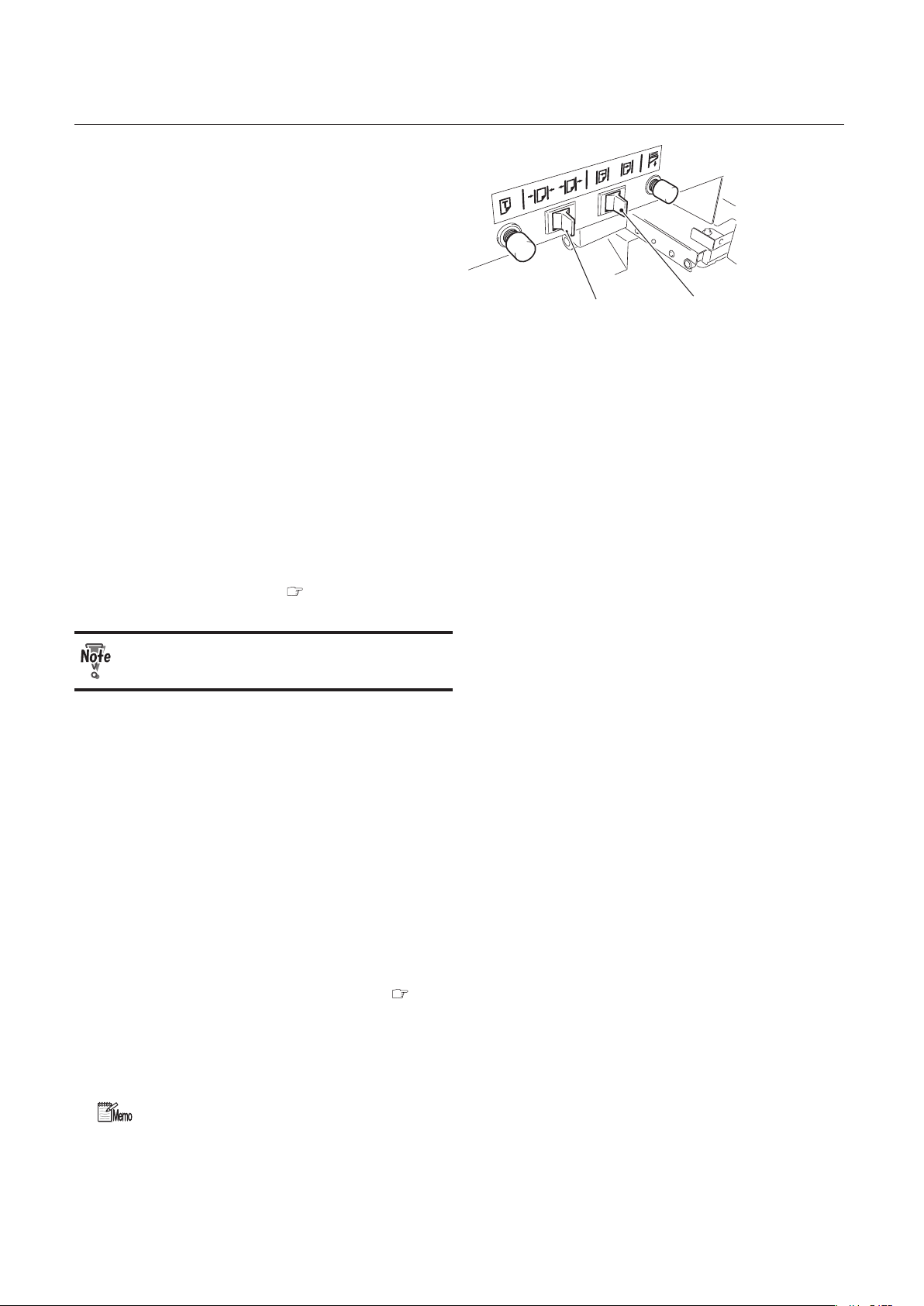
4-6
CHAPTER 4 FINE-ADJUSTMENT AND OPTION SETTING
Guide adjustment switch A
Guide adjustment switch B
You can fine adjust the paper feed guides
using the guide adjustment switches above
the paper feed tray when there is a cover
on the nipping station.
When you move the guide adjustment
switch A to the left, the nipper guides will
move closer to each other. When you move
the guide adjustment switch A to the right,
the nipper guides will move farther from
each other.
When you move the guide adjustment
switch B to the left, the nipper guides will
move to the operator's side. When you
move the guide adjustment switch B to the
right, the nipper guides will move to the
non-operator's side.
The increment of the guide adjustment
switch for the nipping guide is same as for
the paper feed guide ( p.4-2).
When there is no cover on the nipping
station, the paper feed guide will move.
3.
Press the move button 5 or 6 to adjust the position of the positioning fingers.
Fine-adjustment range: 0 to 25.0 mm (0 to 0.10 inch)
Move button 5: The positioning fingers move to the left.
Move button 6: The positioning fingers move to the right.
The increment you selected in step 2 will be automatically applied to the positioning fingers.
To change the increment, press the increment change button and select the increment from
0.1 mm/0.5 mm/1.0 mm (0.004 inch/0.02 inch/0.04 inch).
You can also adjust the positioning fingers by turning the positioning finger adjustments in the
range of 0 to 4 mm (0 to 0.16 inch) ( p.3-11).
4.
Press the return button to return to the screen used in step 1.
The nipping station will go down.
You can fine adjust the scoring width with the main cover open. After completing the
fine-adjustment, make sure that you close the cover.
Page 93

4-7
CHAPTER 4 FINE-ADJUSTMENT AND OPTION SETTING
1-4. Setting the Nipper
If the spine is too round or too sharp, adjust the width of the nipper.
Nipper
Select Button
1.
Select the nipper select button.
The screen for adjusting the nipper will
appear. If you have not performed a size
change, the screen will not appear.
Increment Change Button
Nipper Fine-adjustment
Previous Button
Move Button 1
Move Button 2
2.
Press the move buttons to adjust the
nipper.
Fine-adjustment range: –2.0 to 5.0 mm
(–0.08 to 0.20 inch)
Move button 1: The nipper moves farther
from each other.
Move button 2: The nipper moves closer to
each other.
Increment change button:
You can select the increment from 0.1
mm/0.5 mm/1.0 mm (0.004 inch/0.02
inch/0.04 inch).
: 0.1 mm (0.004 inch)
: 0.5 mm (0.02 inch)
: 1.0 mm (0.04 inch)
3.
Press the return button to return to
the screen used in step 1.
To know the current width of the nipper, press the nipper guide select button ( p.4-5).
When you press the nipper guide select button, the nipper guides will go up and the
nipper width will be the same as the book block width. Then you will know the
current width of the nipper.
Page 94

4-8
CHAPTER 4 FINE-ADJUSTMENT AND OPTION SETTING
1-5. Setting the Glue Cutting Position
A spine glue cutting position is adjusted automatically according to the book block length. However if
you want to change the position, you can adjust the starting and ending points of spine glue.
Glue Cutting
Position
Select Button
1.
Press the glue cutting position select
button.
The screen for adjusting the glue cutting
position will appear.
2.
Press or to change the glue
cutting position (starting point).
Each time you press the button, the glue
cutting position will change by 0.5 mm (0.02
inch).
Fine-adjustment range: ±50.0 mm (1.97 inches)
3.
Press or to change the glue
cutting position (ending point).
Each time you press the button, the glue
cutting position will change by 0.5 mm (0.02
inch).
Fine-adjustment range: ±50.0 mm (1.97 inches)
Previous Button
Glue cutting position
(starting point)
Glue cutting position
(ending point)
Example
3.0
2.5
2.0
● When the fine-adjustment value is "0.0," glue will run off the edge (starting point)
because the wiper does not move and the glue cutting position is not adjusted.
● If you cannot adjust the glue cutting position as desired even after selecting the
maximum value, contact your dealer.
4.
Press the return button to return to
the screen used in step 1.
Page 95

4-9
CHAPTER 4 FINE-ADJUSTMENT AND OPTION SETTING
1-6. Setting the Width of Side Glue
The width of the side glue is adjusted automatically according to the book block thickness. However, if
you want to change the width, adjust the distance between the side glue rollers.
Side Glue Width
Select Button
1.
Press the side glue width select
button.
The screen for adjusting the side glue width
appears. If you have not performed a size
change, the screen will not appear.
Also, if the glue tank has not reached the
certain temperature (the set temperature
minus 20°C/68°F), the caution message
is displayed and the screen for setting the
side glue width does not appear.
Side Glue Roller Width Fine-adjustment
Previous Button
Move Button 1
Move Button 2
Increment Change Button
Side Glue Meter
Adjustment Button
2.
Press the move button to adjust the
width of side glue.
Fine-adjustment range:
–2.0 to +5.0 mm (–0.08 to 0.20 inch)
Move button 1:
The distance between the side glue
rollers will be longer and the amount of
glue attached to the sides will decrease.
Move button 2:
The distance between the side glue
rollers will be shorter and the amount of
glue attached to the sides will increase.
Increment change button:
You can select the increment from 0.1 mm/0.5 mm/1.0 mm (0.004 inch/0.02 inch/0.04 inch).
: 0.1 mm (0.004 inch)
: 0.5 mm (0.02 inch)
: 1.0 mm (0.04 inch)
Side glue meter adjustment button:
When the side glue rollers are open to the maximum, the side glue roller on the operator's
side comes under the external cover and therefore you cannot adjust the side glue meter. If
you press the side glue meter adjustment button, the side glue roller moves to the position
where you can adjust the side glue meter.
3.
Press the return button to return to the screen used in step 1.
Page 96

4-10
CHAPTER 4 FINE-ADJUSTMENT AND OPTION SETTING
1-7. Adjusting Spine Glue Amount
Check the finished booklet and adjust the amount of the spine glue and side glue if necessary.
No.1 Glue Drum Meter Adjustment
Adjusts the glue amount to be applied to the application No.1 drum.
Spine meter roller
adjustment
Application
No.1 dru
m
No.1 meter
No.2 meter
Side glue meter
(operator’s side)
Side glue meter
(non-operator’s side)
No.2 glue drum
meter adjustment
No.1 glue drum
meter adjustment
Side glue meter
adjustment
(operator’s side)
Application
No.2 drum
Side glue meter adjustment
(non-operator’s side)
Side glue roller
(non-operator’s
side)
Spine meter
roller
Side glue roller
(operator’s side)
Base position:
The indicator on the No.1 glue drum
meter adjustment points to the left.
Turning to the left:
The amount of the glue applied to the
drum is largest.
Turning to the right:
The amount of the glue applied to the
drum is smallest.
No.2 Glue Drum Meter
Adjustment
Adjusts the glue amount to be applied to the
application No.2 drum.
Base position:
The indicator on the No.2 glue drum
meter adjustment points to the left.
Turning to the left:
The amount of the glue applied to the
drum is largest.
Turning to the right:
The amount of the glue applied to the
drum is smallest.
Spine Meter Roller Adjustment
Adjusts the amount of glue applied to the spine.
Base position:
The indicator on the spine meter roller
adjustment points to the right.
Turning to the left:
The amount of the glue applied to the
drum is smallest.
Turning to the right:
The amount of the glue applied to the
drum is largest.
Page 97

4-11
CHAPTER 4 FINE-ADJUSTMENT AND OPTION SETTING
Locking screw
Adjustment
1.
Turn the locking screw to the left to
loosen the adjustment.
2.
Move the adjustment to the desired
position.
3.
Turn the locking screw to the right to
tighten the adjustment.
1-8. Adjusting Side Glue Amount
When the side glue amount is different between the right and left sides of a finished booklet, move the
side glue meter to adjust the side glue amount.
Side Glue Meter
Turning the side glue meter adjustment changes the side glue amount.
If the side glue meter on the operator's side is positioned under the external cover, move it to the nonoperator's side by pressing the side glue meter adjustment button on the touch panel screen (
p.4-9).
Wrench
Screw
Screw
Wrench
Side glue meter
1.
Loosen the screws (each 2) using
the supplied wrench (opposite side
distance 3 mm).
.
Spanner
Side glue meter adjustment
(operator’s side)
Side glue meter
adjustment
(non-operator’s side)
2.
Turn the side glue meter adjustment
using the supplied spanner to adjust
the amount of glue.
Turn the adjustment little by little checking
the glue amount.
The iron spanner gets hot. Do not
continue to use it for a long time.
3.
Tighten the screws (each 2) using
the supplied wrench (opposite side
distance 3 mm).
Page 98

4-12
CHAPTER 4 FINE-ADJUSTMENT AND OPTION SETTING
● Before adjusting the glue amount, make sure that the hot melt glue is completely
melted.
● The temperature around the glue tank is very high. Be careful when you adjust the
glue amount.
● Be careful not drop the supplied tools inside the glue tank.
● High voltage of electricity supplied to the glue tank may cause an electric shock. Be
careful.
1-9 Adjusting the Nipping Station
When the spine of the finished booklet is round or when there is some space between the book block
and the cover, you may need to adjust the height of the nipping station. Check the finished booklets
and adjust the height of the nipping station if necessary.
Nipper level
adjustment access
1.
Open the nipper level adjustment
access.
2.
Move the adjustment lever seeing the
scale.
Adjustment lever
Fine-adjustment range:
–1.5 to +0.5 mm (–0.06 to +0.02 inch)
Base position: -0.5
Turning the lever to the + direction will raise
the height of the nipping station.
Turning the lever to the – direction will
lower the height of the nipping station.
3.
Close the nipper level adjustment
access.
Page 99

4-13
CHAPTER 4 FINE-ADJUSTMENT AND OPTION SETTING
2.
Using Motion Check
Press the motion check tab to eject jammed cover or a finished booklet, to change the level of the
paper feed tray, or to move the clamp. Press the main menu tab to return to the main menu.
Motion Check Tab
2-1. Ejecting Jammed Paper
Paper ejection
button
When a paper jam has occurred on the
paper feed tray, the caution message will
appear. Press the paper ejection button to
remove the jammed paper.
If the message does not appear, press the
paper ejection button on the motion check
menu. While you are pressing down the
button, the conveyance motor will keep
turning.
Paper Ejection
Button
If you cannot remove the jammed paper
by pressing the paper ejection button,
remove it by hand.
2-2. Discharging Booklet
When a booklet is left in the clamp, the
caution message will appear.
Press the booklet ejection button to
discharge the booklet. The level plate will
open to drop the booklets on the stacker.
Booklet Ejection
Button
Page 100

4-14
CHAPTER 4 FINE-ADJUSTMENT AND OPTION SETTING
2-3. Adjusting the Height of Paper Feed Tray
When you add paper during binding operation, press the paper feed tray up/down button to raise or
lower the paper feed tray. When the paper feed tray is at its highest position or in a middle position, it
will descend. When it is at its lowest position, it will rise.
Paper Feed Tray
Up/Down Button
While the paper feed tray is rising or descending, the message will be displayed on the touch panel
screen.
You can descend the paper feed tray by pressing the feed tray down button above the
paper feed tray. (
p.1-9)
2-4. Moving the Clamp
Before cleaning the level plate, press the clamp horizontal movement button to move the clamp to the
right. The clamp will move to the nipping section ( p.5-3).
Clamp horizontal
Movement Button
Before pressing the clamp horizontal movement button, make sure that there is no one
around the clamp section and the nipping section.
 Loading...