

Page 1

Provided By
http://www.MyBinding.com
http://www.MyBindingBlog.com
Page 2

SERVICE TRAINING MANUAL
DocuCutter™
DC-545 & DC-545HC
Page 3

DocuCutter 545
Table Of Contents
Table Of Contents...............................................................................................................2
Product Overview ...............................................................................................................3
Programmable Memory...................................................................................................4
Automatic Operation via Barcode....................................................................................6
Automatic Registration Correction...................................................................................6
Safety .................................................................................................................................8
Cutter and Slitter Blades .................................................................................................9
Safety Notes..................................................................................................................10
Maintenance Safety ......................................................................................................11
Electrostatic Discharge (ESD) Protection Program.......................................................11
DocuCutter DC-545 Installation........................................................................................12
The Control Panel.............................................................................................................14
AF-100 OPERATOR CONTROLS ................................................................................17
PWB Locations.................................................................................................................19
Switch and Sensor Locations............................................................................................20
Paper Handling.................................................................................................................22
Paper Path....................................................................................................................23
Slitting ...........................................................................................................................24
Cutting...........................................................................................................................27
Creasing........................................................................................................................29
AF-100 Theory Of Operation ............................................................................................31
Programming Jobs........................................................................................................32
DC-545: AUTO CUT function........................................................................................34
DC-545 Theory of Operation.........................................................................................36
Reasons for JAM and ERROR messages........................................................................39
DocuCutter DC-545 Maintenance Procedures..............................................................41
DocuCutter DC-545 Service Mode ...................................................................................42
Documentation Review ........................................................................................................44
Conclusion............................................................................................................................45
2 DocuCutter 545 Training Guide © 2002, Duplo USA Corporation
Page 4

Product Overview
DocuCutter 545
The DocuCutter DC-545 is a fully automatic four-sided
paper trimmer. In addition to four sided trimming, it can
also perform up to five parallel margin slits (a sixth slitter
is available as an option), multiple leading and trailing
edge cuts (up to 10) and multiple sheet creases (up to 4).
Full bleed color documents are finished in a single pass
with no operator intervention. The DocuCutter DC-545
produces postcards, greeting cards, photo albums,
business cards, and much more.
The optional DC-545HC configuration includes:
AF-100 autofeeder
Stand
The DC-545HC configuration is shown on the cover of this
manual. The DocuCutter DC-545 is shown in Figure 1
below.
Figure 1. The DocuCutter DC-545
© 2002, Duplo USA Corporation DocuCutter 545 Training Guide 3
Page 5

DocuCutter 545
Programmable Memory
The DocuCutter DC-545 is manually programmable so
additional jobs (up to 80 total) may be designed and
stored for future use. See Section 6 of the DocuCutter
DC-545 Service Manual for programming details.
4 DocuCutter 545 Training Guide © 2002, Duplo USA Corporation
Page 6

DocuCutter 545
The major components of the DocuCutter DC-545 are
shown in Figure 2 below.
Figure 2. Major Components - View A
The remaining major components of the DocuCutter DC545 are shown in Figure 3 below.
Figure 3. Major Components - View B
© 2002, Duplo USA Corporation DocuCutter 545 Training Guide 5
Page 7

DocuCutter 545
Automatic Operation via Barcode
The operator places a single sheet of preprinted output
containing a properly formatted code 39 barcode in the
feed tray of the DocuCutter DC-545 (or in the feed tray of
the AF-100 on HC version systems). See the DC-545
Instruction Manual for bar code and registration mark
details. The preprinted output contains a barcode
indicating which preprogrammed job the DocuCutter DC545 needs to execute. The DocuCutter DC-545
automatically sets the slitter positions, activates the cutter
for lead/trail edge trimming and the creaser for any
required crease(s).
Automatic Registration Correction
The DC-545 reads a small 90-degree angle registration
mark, adjacent to the barcode. It is used for cutting,
creasing, and trimming registration correction. The REG
mark reference position is input during entry of each set of
programming parameters. Since the REG mark and image
shift proportionately, any error in the REG mark position is
used as error correction data for image registration. The
DocuCutter DC-545 automatically compares the actual
image position to the reference position and offsets the
cutting and creasing position (horizontal shift) and slit
position (vertical shift) to maintain precise trims—every
time.
6 DocuCutter 545 Training Guide © 2002, Duplo USA Corporation
REG Mark
Left Margin Slitter (LEFT SL)
Center Left Slitter (C.L. SL)
Center Slitter (OP1)
PAPER FEEDING DIRECTI ON
Bar Code
Right Margin Slitter (RGHT SL)
Center Right Slitter (C.R. SL)
Page 8

DocuCutter 545
DocuCutter DC-545 Specifications
The table below provides the specifications applicable to
the DocuCutter DC-545. This information is provided for
reference purposes only.
Paper size
Finishing size
Paper thickness
Front edge cutting width
Rear edge cutting width
Side cutting width
Cutting accuracy
Cutting speed
Feeding method
Stacker
Power supply
Maximum = 12.6" x 18"
Minimum = 8.5" x 11"
Minimum = 2" x 3.5"
(business card size)
28 lb bond to 10 pt cover
(80-230 gsm)
0.125" Minimum
0.125" Minimum
3" Maximum
0.125" Minimum
±0.762 mm
2 ppm Minimum
Manual feeding (3.93” stack
with AF-100 vacuum feeder
in the HC configuration)
Drop type
AC 120 V ±10 % @ 60 Hz
Current consumption
Machine dimensions
2.1A
44.5W x 22D x 11H in.
1130W x 559D x 279H mm
Machine weight
Main body: 127 lb. (58 kg)
© 2002, Duplo USA Corporation DocuCutter 545 Training Guide 7
Page 9

DocuCutter 545
Safety
The objective of this section is to familiarize you with the
safety requirements related to the operation and servicing
of the DocuCutter DC-545. By reading this section, you
will gain an understanding of the important safety
information relating to this product.
NOTE One of the most important goals of this section is to give
you enough information so that you will always take the
proper safety precautions when servicing this product.
• At no time will you ever be instructed to come in
contact with internal drive components or high
voltage electrical devices that are under power. In
fact, the first step in most service procedures is “disconnect power cords.”
• At no time should you ever instruct an operator to
touch any moving or powered internal components.
• The only time that power is left on during a service
procedure is when specific components are being
tested.
All safety devices and covers should be in place and in
working order before completing a service call. It is your
responsibility to follow safe work procedures at all times. If
you perform an unapproved service procedure, you may
run the risk of injuring yourself or the people nearby. Also,
you could be inadvertently demonstrating a dangerous
service procedure to a customer. This could result in a
severe injury and an expensive lawsuit.
8 DocuCutter 545 Training Guide © 2002, Duplo USA Corporation
Page 10

DocuCutter 545
Cutter and Slitter Blades
Because the DocuCutter DC-545 contains a series of
Slitters and a Cutter, a variety of Warning Labels have
been placed on the machine. You should be aware of the
Warning Label locations, as shown in Figure 4 below.
WARNING The Cutter Blade and the Slitter Blades could cause
serious injury if not handled properly. Always use
caution when working near the Cutter or Slitters.
Keep the Warning Labels clean at all times. If Labels
become damaged, replace them.
© 2002, Duplo USA Corporation DocuCutter 545 Training Guide 9
Figure 4. Warning Label Locations
Page 11

DocuCutter 545
Safety Notes
The DocuCutter DC-545 has been designed and tested to
meet strict safety requirements. These include safety
agency examination and approval, and compliance to
established environmental standards. The following notes
and warnings will help to ensure your complete
understanding of the safety requirements for the
DocuCutter DC-545:
• ALWAYS follow all warnings and instructions marked
on, or supplied with, the equipment.
• ALWAYS disconnect the machine from the wall outlet
before cleaning.
• ALWAYS use the materials and supplies specifically
designed for this machine. Use of unsuitable materials
may result in poor performance and possibly create a
hazardous situation.
• ALWAYS ensure that the machine is located on a solid
support surface with adequate strength for the weight of
the machine.
• NEVER use any supplies or cleaning materials for
purposes other than what they were intended.
• NEVER push objects of any kind into the slots of the
machine as they may touch dangerous voltage points or
cause a short circuit in parts that could result in a risk of
fire or electric shock.
• NEVER push objects of any kind into the ventilation
openings in the back and bottom of the machine.
• NEVER allow anything to rest on the power cord.
• NEVER use a ground adapter plug to connect the copier
to a power source receptacle that lacks a ground
connection terminal.
• ALWAYS make sure that the total amperage of all
products plugged into the wall outlet does not exceed
the outlet protection.
10 DocuCutter 545 Training Guide © 2002, Duplo USA Corporation
Page 12

DocuCutter 545
Maintenance Safety
• DO NOT use aerosol cleaners. Follow the instructions in
the Service Manual for proper cleaning methods.
• DO NOT use this machine near water, wet locations, or
outdoors.
• NEVER attempt any maintenance function that is not
specified in the Service Manual, or as directed by an
authorized service representative.
• NEVER spill liquid of any kind on the machine.
Electrostatic Discharge (ESD) Protection Program
The purpose of the Electrostatic Discharge (ESD)
Protection Program is to preserve the inherent reliability
and quality of electronic components that are handled by
field service personnel. This program is implemented as a
direct result of advances in micro circuitry technology, as
well as a new acknowledgment of the magnitude of the
ESD problem in the electronics industry today.
This program will reduce field service costs that are
charged to PWB failures. Approximately 90% of all PWB
failures that are ESD-related do not occur immediately.
Using the ESD Field Service Kit will eliminate these
delayed failures and intermittent problems caused by
ESD. This will improve product reliability and reduce
callbacks.
The ESD Field Service Kit should be used whenever
Printed Wiring Boards or ESD-sensitive components are
being handled. This includes activities like replacing or
reseating circuit boards or connectors. The kit should also
be used to prevent additional damage when circuit boards
are returned for repair.
© 2002, Duplo USA Corporation DocuCutter 545 Training Guide 11
Page 13

DocuCutter DC-545 Installation
These instructions are for installing the DC-545 base unit.
Refer to the Duplo AF-100 Installation Manual for details
on installing the DC-545HC configuration (including the
AF-100 autofeeder and the associated stand).
The following Installation notes are provided as a
reference.
• The DocuCutter DC-545 should be installed on a
• The Paper Tray should be attached to the main
DocuCutter 545
flat and stable surface (the machine weighs 127
pounds / 58 kg). As a precaution, on every service
call, be sure to verify that the customer has the
machine installed in an appropriate location.
body of the DocuCutter DC-545 as shown in Figure
5.
Figure 5. Attaching the Paper Tray
The power cord should be attached to the DocuCutter DC545 and a wall outlet, as shown in Figure 6.
12 DocuCutter 545 Training Guide © 2002, Duplo USA Corporation
Page 14

DocuCutter 545
Figure 6. The Power Cord Location
© 2002, Duplo USA Corporation DocuCutter 545 Training Guide 13
Page 15

The Control Panel
DocuCutter 545
The Control Panel on the DocuCutter DC-545 performs
the following functions:
• Displays operation and machine status during
normal operation
• Indicates when problems with the machine have
occurred
• Allows for operator /service input to assist in jam
clearance
• Provides service personnel with a method of
accessing the Service Mode Diagnostic Tools
The location of the Control Panel on the DocuCutter DC545 is shown in Figure 7.
14 DocuCutter 545 Training Guide © 2002, Duplo USA Corporation
Figure 7. Control Panel Location
Page 16

DocuCutter 545
Each of the Control Panel areas is shown in Figure 8
below. The function of each area is described in the table
that follows.
Cover Lamp
Jam Lamp
Paper Lamp
LCD Panel
F
Button
Power Lamp
Numerical
Clear
Button
Key Pad
Mode
Button
+ Button
- Button
Set
Button
Figure 8. The Control Panel
Start Button
and Start
Lamp
STOP
Button
The Liquid Crystal Display (LCD) Panel displays the
status of the machine. Messages are displayed when
an error or paper jam occurs.
The <+> Button ejects the document from the
machine at the time of paper jam. In the service
mode, this button is used to advance through the
various menus and increment adjustment values in a
positive direction.
The< –> Button ejects the document from the
machine at the time of paper jam. In the service
mode, this button is used to advance through the
various menus and increment adjustment values in a
negative direction.
The POWER Lamp lights up when the power is
switched on.
In the HC configuration, (AF-100 autofeeder attached)
the START Button is used to start processing.
While in the stand-alone configuration (DC-545 only,
no AF-100 autofeeder) the START button is not used.
The STOP Button stops cutting after the current sheet is
complete. The STOP Button also clears jam indication
after the paper is cleared. While in the service menu the
STOP Button is used to exit various menus.
During programming, the Numerical Key Pad enters
preset program numbers and job data.
During programming, the CLEAR Button clears data
values. It is also used to clear the total sheets processed
counter.
During programming mode, the SET Button enters data
values. In the HC configuration (AF-100 autofeeder
attached) the SET button is used to process only one
sheet for proofing purposes.
The MODE Button changes the main menu functions.
[RUN] Ready for processing
[SELECT] Manual job selection (as opposed to bar
code)
© 2002, Duplo USA Corporation DocuCutter 545 Training Guide 15
Page 17

DocuCutter 545
In the service mode, this button is used to enter
various service menus.
The COVER Lamp blinks when the front cover, rear
cover, or the waste cover is open.
The JAM Lamp blinks when a paper jam has
occurred.
[INPUT] Programming mode
[SELECT] Manual job selection (as opposed to
automatic job recall via a bar code)
BARCODE Used to toggle barcode mode on/off. When
the values is changed the REG mark and
autocut features are enabled.
In the HC configuration (AF-100 autofeeder attached)
the PAPER Lamp blinks when paper runs out.
16 DocuCutter 545 Training Guide © 2002, Duplo USA Corporation
Page 18

DocuCutter 545
AF-100 OPERATOR CONTROLS
1. Level adjustment lever for adjusting the level of the
paper stack
2. Separator adjustment knob for adjusting the
amount of space between the mechanical paper
separators and the top sheet of paper
3. Airflow adjustment knob for adjusting the amount of
airflow used to separate the sheets in the paper
stack
4. Skew adjustment knob for adjusting the skew of the
paper stack
5. Stoppers for holding the rear edge of the paper
stack
© 2002, Duplo USA Corporation DocuCutter 545 Training Guide 17
Page 19

LCD Panel
DocuCutter 545
The LCD Panel located on the Control Panel displays the
status of the machine and displays messages when an
error or paper jam occurs.
A sample LCD Panel display is shown in Figure 9 below.
Figure 9. The LCD Panel
1. Status - Displays the current operating mode.
2. Preset Number - Displays the Program (P) number.
3. OPTION - An "*" is displayed when the AF-100 is
attached.
4. BAR CODE - When using bar codes "BC" is displayed;
"- -" is displayed when bar codes are not being used.
5. REGISTER MARK - When using register marks "REG"
is displayed; "- -" is displayed when REG marks are not
being used.
6. AUTO CUT - When using the autocut function, "AC" is
displayed; "- -" is displayed when autocut is not being
used.
7. COUNTER - Displays the number of pages processed.
18 DocuCutter 545 Training Guide © 2002, Duplo USA Corporation
Page 20

PWB Locations
DocuCutter 545
The locations of each of the Printed Wiring Boards
(PWBs) in the DocuCutter DC-545 are shown in Figure
10.
Power
PWB
Main
PWB
Panel
PWB
Memory
PWB
Switching
Power Supply
PWB
Figure 10. PWB Locations
© 2002, Duplo USA Corporation DocuCutter 545 Training Guide 19
Page 21

Switch and Sensor Locations
Slitter Sensor
Left Margin
Slitter Sensor
Center Slitter
Left Sensor
DocuCutter 545
The DocuCutter DC-545 contains a series of Switches
and Sensors to determine paper position. The locations of
the Slitter Sensors within the DocuCutter DC-545 are
shown in Figure 11.
Option 1
Figure 11. Slitter Sensor Locations
20 DocuCutter 545 Training Guide © 2002, Duplo USA Corporation
Center Slitter
Right Sensor
Right Margin
Slitter Sensor
Page 22
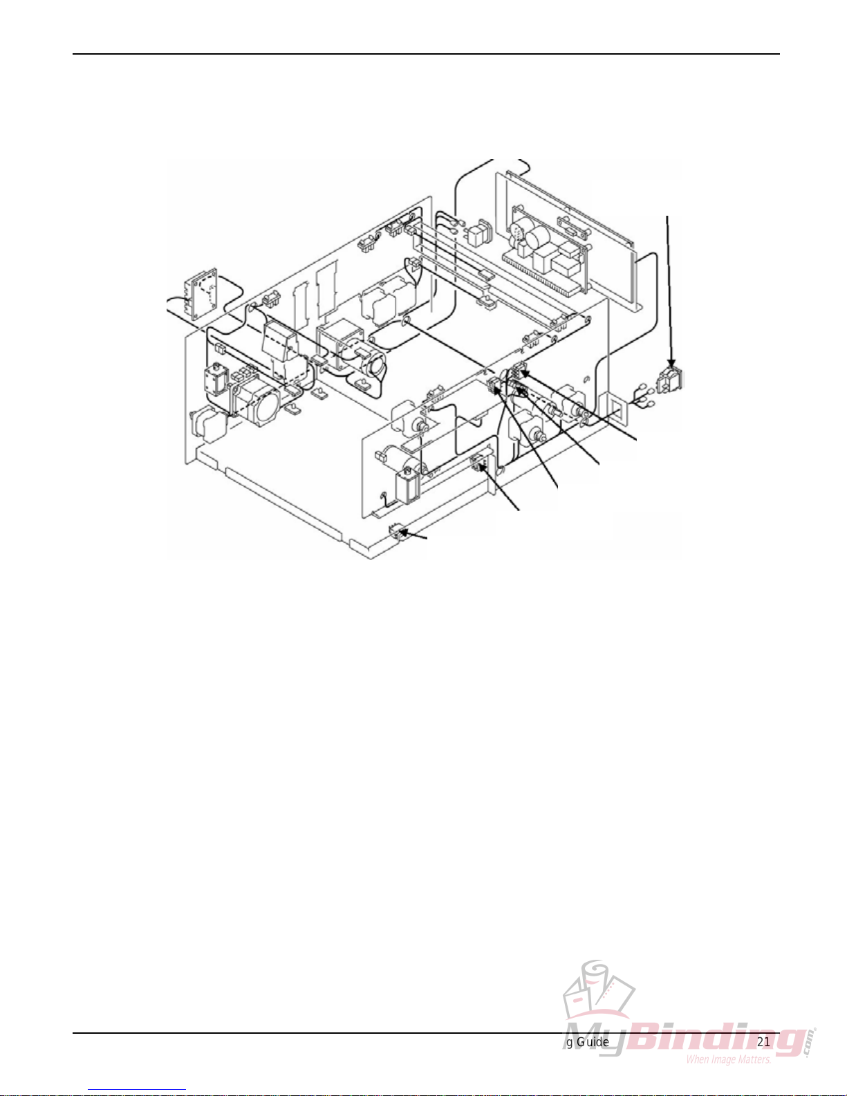
DocuCutter 545
The remaining Switches and Sensors are shown below in
Figure 12.
Power Switch
Tray Switch
Door Switch
Figure 12. Switches and Sensors
Rear Cover Switch
Creaser Sensor
Front Cover Switch
© 2002, Duplo USA Corporation DocuCutter 545 Training Guide 21
Page 23

Paper Handling
DocuCutter 545
Throughout the following paragraphs, you will be reading
about Slitters, a Cutter, and a Creaser. These
components are used in various combinations to finish
documents in the DocuCutter DC-545. Figure 13 is
provided below to help you understand the paper handling
terms associated with the DocuCutter DC-545.
You should note that, by definition, a cut or a crease is
perpendicular to the direction of paper feed, while a slit
is parallel to the paper feed direction.
Cut
REG Mark
(Optional)
Bar Code
(Optional)
PAPER FEEDING DIRECTION
Slit
Crease
22 DocuCutter 545 Training Guide © 2002, Duplo USA Corporation
Figure 13. Paper Handling Terms
Page 24

DocuCutter 545
Paper Path
All of the finishing operations within the DocuCutter DC545 take place along the Main Paper Path. The locations
of the main paper path components are shown in Figure
14.
1212 7345689101113141516
19
20
22 26
21
23
24
25
17 18
28
27
Figure 14. Main Paper Path Components
Names and Locations of Paper Path Components
Item
Number
1 Input Feed Rollers 19 Lower Primary Feed Roller
2 Input Roller 20 Lower Secondary Feed Roller
3 Upper Primary Feed Roller 21 Lower Margin Slitter Drive Gear
4 Upper Secondary Feed Roller 22 Lower Cutter Feed Roller
5 Right (Left) Margin Slitter Lead Screw 23 Lower Creaser Feed Roller
6 Upper Margin Slitter Drive Gear 24 Lower Center Slitter Feed Roller
7 Upper Cutter Feed Roller 25 Lower Center Slitter Drive Gear
8 Cutter Unit 26 Lower Rear Slitter Drive Roller
9 Upper Creaser Feed Roller 27 Lower Rear Slitter Drive Gear
10 Creaser Unit 28 Lower Exit Drive Roller
11 Upper Center Slitter Feed Roller
12 Left Center Slitter Lead Screw
13 Upper Center Slitter Drive Gear
14 Right Center Slitter Lead Screw
15 Upper Rear Slitter Feed Roller
16 Rear Slitter Drive Lead Screw
17 Upper Rear Slitter Drive Gear
18 Upper Exit Feed Roller
Descriptions Item
Descriptions
Number
© 2002, Duplo USA Corporation DocuCutter 545 Training Guide 23
Page 25

DocuCutter 545
Slitting
Standard configuration provides for five Slitters used in
the DocuCutter DC-545. An optional sixth slitter is
available. The five factory provided slitters are called:
• Right Margin Slitter
• Left Margin Slitter
• Center Left Slitter
• Center Right Slitter
• Option 1 Slitter
Two DC Slitter Drive Motors provide cutting energy to
each of the Slitters:
• One DC Slitter Drive Motor provides cutting energy for
the Left Margin Slitter and Right Margin Slitter
• One DC Slitter Drive Motor provides cutting energy for
the Center Left Slitter, Center Right Slitter, and the
Center Slitter.
Cutting Surfaces
Each Slitter consists of a two beveled edge cutting
wheels. Much like a pair of scissors, the two pieces
working together produce a fine cut. Furthermore, the
design provides for high performance with long life
characteristics (1,500,000 sheets).
Cutting Drive
The Slitter’s two cutting wheels are independently driven
by gear driven shafts. The hub of each wheel has a
removable key while the driving shafts have key-ways
located throughout the drive shafts length.
NOTE Use caution while removing the Cutter Units as the keys
can easily fall out.
24 DocuCutter 545 Training Guide © 2002, Duplo USA Corporation
Page 26

DocuCutter 545
Position Detection
Each Slitter has a Sensor Plate mounted to the top of the
Slitter. The Sensor Plate has a slot that permits the Slitter
Sensor to activate when the Slitter is in the home position.
The Sensor Plates are shown in Figure 15.
NOTE The Slitter Sensor Plate can be moved side-to-side
several millimeters when the mounting screws are
loosened. The available movement is for factory setup
and should not be changed. Slitter calibration position is
performed through the service menu.
LEFT SLITTER UNIT POSITION SHAFT
SENSOR PLATE
TO LEFT SLITTER STEPPER MOTOR
LEFT SLITTER UNIT
KEYWAYS
RIGHT SLITTER UNIT
RIGHT SLITTER UNIT POSITION SHAFT
SLITTER DRIVE GEARS
Figure 15. Slitter Components
BEARING
SENSOR PLATE
TO RIGHT SLITTER STEPPER MOTOR
© 2002, Duplo USA Corporation DocuCutter 545 Training Guide 25
Page 27

DocuCutter 545
Slitter Position Drive
Each Slitter has its own positioning drive motor (stepper
motor). The use of a stepper motor ensures highly
accurate positioning of the slitter unit. Each stepper motor
drives a lead screw. The Slitters contain a bearing that
rides on the lead screw, so as the lead screw turns, the
Slitter is driven from side to side. Direction of the Slitter
movement is determined by the stepper motor control
signal.
Slitter Positioning
Each job contains position information for the Slitters. The
program information sets the Slitter position each time a
sheet is processed. This method provides extremely
accurate performance.
When a job is executed, each stepper motor is driven until
the Slitters arrive at the home position (home position is
next to the side frame where each sensor is located).
Next, the stepper motors drive the Slitters in the opposite
direction, away from the side frame, until the desired
position is obtained. Position information is monitored by
the stepper motor drive signal.
Once the Slitter positions are correct, the DocuCutter
begins to drive the Slitter cutting drive gears, thus
providing slitting energy. Then the drive rollers convey the
paper through the machine.
26 DocuCutter 545 Training Guide © 2002, Duplo USA Corporation
Page 28

DocuCutter 545
Cutting
The DocuCutter DC-545 uses an integrated Cutter to
produce a cut (or multiple cuts) perpendicular to the paper
path, as determined by the program data. The Cutter
specifically enables lead and trail edge cuts so custom
finished sizes and full bleed documents are obtainable. It
also enables multiple cut applications such as business
cards to be produced in a single pass. Cutting is
accomplished using the components listed below:
• A high torque DC motor with a self-contained torque
enhancing transmission
• Long life (2,000,000 cuts), replaceable, precision
upper cutting blade
Cutter Construction
The Cutter Unit consists of a movable, precisely beveled,
Upper Cutting Blade and a counter-cutting surface. Much
like a pair of scissors, the two pieces working together
produce a very fine cut. The design provides for high
performance with long life characteristics.
© 2002, Duplo USA Corporation DocuCutter 545 Training Guide 27
Page 29

DocuCutter 545
Cutting Drive
Energy is supplied to the Cutter Unit by a high torque
drive configuration. The Motor, via a self-contained gear
drive to the Cutter Drive Cam, supplies rotational energy.
The Cam causes the Upper Blade to move towards the
bottom surface, cutting the paper, and then returns the
blade to the home position.
Operational Status
The Cam activates a Micro switch. The Micro switch
signals the Microprocessor that the Cutter Unit has
reached the home position. The Cutter Unit is cycled each
time the DocuCutter DC-545 is powered on. If the
Microprocessor fails to receive the home position signal, a
jam is declared and the LCD indicates CUTTER LOCK.
Cutting Position Detection
The preset job data indicates where the paper requires
cutting. When the lead edge of the paper triggers Paper
Path Sensor #3 (PPS3), the Microprocessor calculates the
distance the paper travels via the Stepper Motor Control
pulses. When the desired distance is reached, the Cutter
Drive Motor is activated and the paper is cut.
28 DocuCutter 545 Training Guide © 2002, Duplo USA Corporation
Page 30

DocuCutter 545
Creasing
The DocuCutter DC-545 uses an integrated Creaser to
produce a crease (or multiple creases) perpendicular to
the paper path, as determined by the program data. The
crease enables smooth, even forming of finished paper so
it may be folded easily after processing. Creasing also
permits folding of color printed documents with minimal
toner cracking or flaking.
Creasing is accomplished in the DocuCutter DC-545 with
the following components:
• A high torque DC Motor with a self-contained torque
enhancing transmission
• Long life, high-precision male and female paper
creasing surfaces
Creaser Construction
The upper and lower surfaces of the Creaser are
designed to mesh when they are pressed together. One
surface has a channel and the other surface has a ridge
that fits into the channel.
Creasing Drive
Energy is supplied to the Creaser by a high torque drive
configuration. Rotational energy is supplied by the motor,
through a self-contained gear drive, to a Drive Belt and
ultimately to the Creaser Drive Pulley. The Pulley is
directly connected to an Eccentric Shaft. When the Shaft
is driven, the eccentricity causes the upper creasing
surface to move towards the lower creasing surface, thus
creasing the paper.
Operational Status
The Camshaft activates a Photo Interrupter. The Photo
Interrupter signals the Microprocessor that the Creaser
Unit has reached the home position. The Creaser Unit is
cycled each time the DocuCutter DC-545 is powered on. If
the Microprocessor fails to receive the home position
signal, a jam is declared and the LCD indicates
CREASER LOCK.
© 2002, Duplo USA Corporation DocuCutter 545 Training Guide 29
Page 31

DocuCutter 545
Creasing Position Detection
The preset job data indicates where the paper requires a
crease. When the lead edge of the paper triggers PPS3,
the microprocessor calculates the distance the paper
travels via the Stepper Motor control pulses. When the
desired distance is reached, the Creaser Drive Motor is
activated and the paper is creased.
30 DocuCutter 545 Training Guide © 2002, Duplo USA Corporation
Page 32

AF-100 Theory Of Operation
DocuCutter 545
The following describes the operating principle of the AF100 Autofeeder.
1. The operator loads a stack of paper in the AF-100
feed tray and then presses the START button on
the DC-545.
2. The paper sensor (11) detects the presence of
paper and allows the blower (13) and vacuum fan
(13) to turn ON.
3. The paper level sensor (15) determines the paper
pile height is at the desired level. The elevator is
raised if the paper pile is not high enough. When
the paper pile reaches the proper height the
elevator stops raising the stack and the vacuum
shutter solenoid (12) turns ON, allowing vacuum
pressure to pick up the top sheet on the pile.
4. The feed motor turns ON and drives the feed belts
in order to feed the sheet into the DC-545. PPS1,
located in the DC-545, senses the paper and
causes the feed motor (13) and the vacuum feed
shutter solenoid to turn OFF.
5. When the finished sheet of paper passes PPS4,
signaling the sheet has exited the DC-545, the feed
process repeats until the paper pile is depleted.
© 2002, Duplo USA Corporation DocuCutter 545 Training Guide 31
Page 33

DocuCutter 545
Programming Jobs
The DocuCutter DC-545 is manually programmable with 80 sets of
available finishing program numbers. An individual set of cutting
dimensions are stored and recalled by a finishing program number.
You may be required to change or add finishing programs
depending upon customer requirements. Follow the steps below to
manually enter a finishing program:
NOTE The information provided here is also available in General
Procedure GP-5 of the DocuCutter DC-545 Field Service Manual. It
is presented in this document for reference purposes only.
1. Power On the DocuCutter.
2. Repeatedly push the <MODE> button until the display indicates
[INPUT].
3. Push and hold the <SET> button until the display appears.
4. Enter the desired program number using the numerical
keypad (01 ~ 80). In this example the program number is 52.
5. Press the [SET] button.
6. Place a PREPRINTED (with a REG mark) sample sheet in the
DocuCutter DC-545.
7. While observing the number on the lower left of the LCD display panel,
push the <+> button until the number changes (a typical change is
approximately 500 to 50, depending on the REG mark position). If the
REG mark goes past the image sensing area, press the <-> button to
move the paper (REG mark) back.
8. Enter the three-digit value from the lower left of the display using the
appropriate key on the keypad. In this example, the value is 52.
9. Press the [SET] button.
10. Remove the sample paper by pressing the <-> button.
11. Measure the distance (in millimeters) between the leading edge of the
paper and the horizontal portion of the REG mark. The value must be
between 5 and 50 millimeters.
12. Enter the value from step 11 using the 10 key keypad.
13. Press the [SET] button.
14. Enter the distance from the left side of the paper to the position for the
15. Press the [SET] button.
16. Enter the distance from the left side of the paper to the position for the
32 DocuCutter 545 Training Guide © 2002, Duplo USA Corporation
left margin slit (LEFT SL) location. This value must be between 0 and
120 millimeters.
right margin slit (RGHT SL) location. This value must be between 200
and 320 millimeters.
Page 34

DocuCutter 545
17. Press the [SET] button.
18. Enter the distance from the left side of the paper to the position for the
center left slit (C.L. SL) location. This value must be between 0 and
160 millimeters.
19. Press the [SET] button.
20. Enter the distance from the left side of the paper to the position for the
center right slit (C.R. SL) location. This value must be between 0 and
320 millimeters. However, the C.R. SL value must be 50 mm greater
than the value of the C.L. SL. This is due to both slitters are on the
same set of cutting drive shafts.
21. Press the [SET] button.
22. Enter the distance from the left side of the paper to the position for the
center (OP1 SL) slit location. This value must be between 0 and 320
millimeters.
23. Press the [SET] button.
24. Enter the distance from the leading edge of the paper to the position
for the first cut (CUT 1) location. This value must be between 0 and
999 millimeters.
25. Press the [SET] button.
26. Enter the distance from the leading edge of the paper to the position
for the second cut (CUT 2) location. This value must be between 0 and
999 millimeters. If a second cut is not required, enter a value of zero.
27. Press the [SET] button.
NOTE: If attempting to enter a lower CUT value than the previous value is
attempted, the DocuCutter will not permit the lower
value to be entered.
28. Enter the distance from the leading edge of the paper to the position
for the first score (SCR. 1) location. This value must be between 0 and
650 millimeters. If a second score is not required, enter a value of zero.
29. Press the [SET] button.
NOTE: If attempting to enter a lower SCR value than the previous value is
attempted, the DocuCutter will not permit the lower
value to be entered.
30. Enter the total length (in millimeters) of the sample paper.
31. Press the [SET] button.
32. Press the <SET> button to retain the settings or <STOP> to discard
the settings. The display will indicate “Memory Please Wait” while the
information is written to the DocuCutter memory circuit. The
memorization process will take approximately 10 seconds.
© 2002, Duplo USA Corporation DocuCutter 545 Training Guide 33
Page 35

DocuCutter 545
A
DC-545: AUTO CUT function
When AUTO CUT is ON, it works under the following
conditions
:
The first cut in the preset program is longer than 17.0
mm.
The distance between the total length entered in the
program and the last cut position entered in the program
is longer than 21.0 mm.
IMPORTANT NOTE ON AUTO CUT
Auto cut works on:
a) The section between the lead edge and CUT 1
and/or
b) The section between the last CUT in the preset
program and the trail edge only. If you want to
have the any other margin cut into pieces, make
sure to add ‘dummy’ cuts of less than 17 mm in the
program. Otherwise, the margin cut can be left in
the machine or ejected on the paper tray.
UTOCUT is
possible in
these
sections only
Lead edge
CUT1
To cut this part into pieces, add
‘dummy’ cuts of less than 17.0mm
in the program.
Last CUT
34 DocuCutter 545 Training Guide © 2002, Duplo USA Corporation
Page 36

DocuCutter 545
IMPORTANT NOTE ON DATA ERROR
When the total number of Scores, Cuts, and AUTO
CUTS exceeds 17, ‘---E6--- DATA ERROR’ is
indicated on the LCD.
© 2002, Duplo USA Corporation DocuCutter 545 Training Guide 35
Page 37

DocuCutter 545
DC-545 Theory of Operation
The following describes the DC-545 base model theory of
operation without the AF-100 autofeeder. For details of
the AF-100 theory, see the AF-100 Theory of Operation.
1. The document is placed in the Feed Tray and
PPS1 detects the presence of the document.
2. After 1.5 seconds, the Feed Solenoid drives down
the Input Rollers.
3. After 100msec, the Gate is driven down by the
Gate Solenoid, and the Feed Motor is turned on to
feed the document.
4. Next, the Main Motor feeds the document.
Note: If PPS2 cannot detect the document, after it has
been fed 30mm since feed initiation, “J2 - FEED JAM” is
displayed.
<When using sheet with a Bar Code>
5. The document is fed from the PPS2 location until
the CCD detects the Bar Code.
6. Note: If the CCD cannot read the Bar Code after
the document is fed 50mm, “E3 - BARCODE
ERROR” will be displayed.
<When using a sheet without a Bar Code>
7. After the document is fed 50mm from the PPS2
location, the slitters return to their home positions
and then move to the positions indicated by the
program number.
36 DocuCutter 545 Training Guide © 2002, Duplo USA Corporation
8. After the slitters are in position, the job is
performed. Go to step 13.
Page 38

DocuCutter 545
Note: If the slitters do not move to their indicated positions
within approximately 5 seconds, “E5 - SLITTER ERROR”
will be displayed.
9. When the CCD scans the Bar Code, the document
feeding stops, and each slitter returns to its home
position.
Note: If the slitters do not return to their home positions
(all slitter sensors aren’t blocked) within approximately 5
seconds, “E5 - SLITTER ERROR” will be displayed.
10. After the slitters return to their home positions, the
slitters move to their indicated positions according
to the preset job data detected by scanning the Bar
Code.
Note: If the slitters do not move to their indicated
positions within approximately 5 seconds, “E5 SLITTER ERROR” will be displayed.
11. After the slitters are positioned properly, the
document is fed until the CCD detects the vertical
line of the REG Mark.
Note: If the CCD cannot scan the vertical line within 10
mm of feeding, “E4 - REG MARK ERROR will be
displayed.
12. Each slitter is adjusted for any registration error.
13. The document is fed backwards until PPS2 detects
its leading edge.
© 2002, Duplo USA Corporation DocuCutter 545 Training Guide 37
14. The document is fed by 0.1mm increments until the
CCD detects the horizontal line of the REG Mark.
Page 39

DocuCutter 545
Note: If the CCD cannot scan the horizontal line within
50mm of feeding, “E4 - REG MARK ERROR” will be
displayed.
15. After the horizontal component of the REG Mark is
scanned, any required error correction is
calculated. Horizontal registration correction is
performed during the cutting and creasing
processes.
16. The document processing begins.
38 DocuCutter 545 Training Guide © 2002, Duplo USA Corporation
Page 40

DocuCutter 545
Reasons for JAM and ERROR messages
1. When turning on the power, if any Paper Path
Sensor (PPS1 – PPS4) is blocked, “J1 - REJECT
PAPER” will be displayed.
2. If PPS3 cannot detect the document, after it is fed
10 cm since PPS2 detects it, “J3 - CENTER JAM”
will be displayed.
3. If PPS3 has been blocked, after document is fed its
entire length since PPS3 detects it, “J3 - CENTER
JAM” will be displayed.
4. If PPS4 cannot detect the document, after it is fed
44 cm since PPS3 detects it, “J4 - SLITTER JAM”
will be displayed.
5. If PPS4 has been blocked, after the document is
fed its entire length since the PPS4 detected it, “J4
- SLITTER JAM” will be displayed.
6. If the Upper Blade of the cutter unit does not return
to the home position (the Cutter Position Switch is
not closed) within 400msec since the cutter
movement initiation, “J7 - CUTTER LOCK” will be
displayed.
7. If the Upper Blade of the score unit does not return
to the home position (the Score Position Switch is
not blocked) within 3 seconds since the score
movement initiation, “J8 - CREASE LOCK” will be
displayed.
© 2002, Duplo USA Corporation DocuCutter 545 Training Guide 39
8. If the covers are opened while the machine is
running, “E1 - COVER OPEN” will be displayed.
Page 41

DocuCutter 545
9. If the CCD does not communicate with the Main
PWB, “E2 - RS232C ERROR” will be displayed.
10. If the number of cuts exceeds 10, “E6 - DATA
ERROR will be displayed.
40 DocuCutter 545 Training Guide © 2002, Duplo USA Corporation
Page 42

DocuCutter 545
DocuCutter DC-545 Maintenance Procedures
The following Maintenance procedures are available in the
DocuCutter DC-545 Field Service Manual. They are
presented here for information only.
;Q W YKNN WUG VJ G IWK FGNK PGU UJ QYP K P 6C DNG VQ RGTHQTO
OC K PVGPC PEG VY K EG C [GC T QP VJ G &Q EW %W VVGT &%
DC UGF QP PQ OQTG VJ C P GK IJ V J QWTU WUG C FC [ J GC XK GT
WUG YKNN TGSWK TG OQTG H TGSWGPV OC K PVGPC PEG
ITEM ACTION
PPS1 (Paper Path Sensor 1) Use a brush to clean any paper dust, etc. from the
upper and lower sensor portions.
PPS2 (Paper Path Sensor 2) Use a brush to clean any paper dust, etc. from the
upper and lower sensor portions.
PPS3 (Paper Path Sensor 3) Use a brush to clean any paper dust, etc. from the
upper and lower sensor portions.
PPS4 (Paper Path Sensor 4) Use a brush to clean any paper dust, etc. from the
upper and lower sensor portions.
PAPER LEVEL SENSOR Use a brush to clean any paper dust, etc. from the
sensor.
ROLLERS Use a lint free cloth moistened with water to clean the
Rollers.
ROLLER BEARINGS Clean and oil the Roller Bearings.
SUCTION BELTS Clean the Belts with rubber belt cleaner.
SLITTERS Clean and oil the Slitters.
CUTTER Clean and oil the Cutter Assembly.
Table 1. Recommended Maintenance Schedule
© 2002, Duplo USA Corporation DocuCutter 545 Training Guide 41
Page 43

DocuCutter 545
DocuCutter DC-545 Service Mode
Entering the Service Mode in the DocuCutter DC-545
enables you to perform a variety of diagnostic tests.
NOTE The information provided here is also available in General
Procedure GP-4 of the DocuCutter DC-545 Field Service
Manual. It is presented in this document for reference
purposes only.
The procedure for entering the Service Mode follows:
1. If the machine is already powered on, power off the
machine.
2. While depressing the STOP button, power on the
machine. A buzzer will sound to indicate you are
entering the Service Mode.
3. Press the <+> or <-> buttons to scroll through the
available Service Mode diagnostic selections.
4. When you locate the appropriate Service Mode
diagnostic selection, press the START button.
To exit the Service Mode, press the STOP button and
switch the power off.
42 DocuCutter 545 Training Guide © 2002, Duplo USA Corporation
Page 44

DocuCutter 545
The Service Modes are described in Table 2.
HELP CODE Content
H-00 ROM version indication
H-01 Total cut counter
H-02 Total feed counter
H-03 P.P.S.1 check
H-04 P.P.S.2 check
H-05 P.P.S.3 check
H-06 P.P.S.4 check
H-07 P.P.S.5 check
H-08 Sensor & switch check
H-09 DIP SW status check
H-10 Feed motor check
H-11 Feed solenoid check
H-12 Left margin slitter check
H-13 Right margin slitter check
H-14 Left center slitter check
H-15 Right center slitter check
H-16 OP1 slitter check
H-17 Main motor check
H-18 Score check
H-19 Cutter check
H-20 Slitter blade drive check
H-21 LED check
H-22 CCD performance check
H-23 Total score counter
H-24 Slitter position adjustment
H-25 RAM initialize
H-26 Score distance adjustment
H-27 P.P.S.2 & CCD distance adjustment
H-28 OP2 slitter check (Option slitter 2)
H-29 Elevator check (Optional AF-100)
H-30 Fan Check (Optional AF-100)
H-31 Solenoid & Feed check (Optional AF-100)
H-32 Feeder Total check (Optional AF-100)
H-33 SPEED UP – Prevents slitters from returning home
while in REG mark correction mode.
© 2002, Duplo USA Corporation DocuCutter 545 Training Guide 43
Table 2
Page 45

Documentation Review
DocuCutter 545
You will be required to use DocuCutter DC-545 Field
Service Manual when servicing the DocuCutter DC-545
machine. The Manual contains the following sections:
• Section 1 - Service Call Procedures
• Section 2 - Status Indicator RAPs
• Section 3 – Output Quality RAPs
• Section 4 - Repairs/Adjustments
• Section 5 - Parts List
• Section 6 - General Procedures
• Section 7 - Wiring Data
Many of the topics described in this training guide are
described in detail in the Field Service Manual. As always,
you should make the Field Service Manual your main
source for obtaining service information.
When servicing the DocuCutter DC-545, you should also
be aware of the information available in the Duplo
DocuCutter DC-545 Instruction Manual. The Duplo
DocuCutter DC-545 Instruction Manual provides a variety
of information for customers, including both operating and
troubleshooting information.
44 DocuCutter 545 Training Guide © 2002, Duplo USA Corporation
Page 46

Conclusion
DocuCutter 545
Congratulations!! You have completed the DocuCutter
DC-545 Training Guide. You should now be able to:
• Understand and describe the main components and
features of the DocuCutter DC-545.
• Be able to operate the DocuCutter DC-545.
• Be familiar with all of the documentation available
for servicing and operating the DocuCutter DC-545.
• Understand the important safety precautions
required when servicing the DocuCutter DC-545.
• Be familiar with the steps required to program jobs
in to the DocuCutter DC-545.
• Be able to enter the Service Mode of the
DocuCutter DC-545.
• Understand how to set the adjustments on the AF-
100 autofeeder
• Understand the AF-100 operation theory.
If you have any questions about the features and
functions of the DocuCutter DC-545, or this manual,
review the appropriate Service Manual, or the Product
Operation Manual as required.
© 2002, Duplo USA Corporation DocuCutter 545 Training Guide 45
Page 47

Guaranteed Lowest Prices on an
Endless Selection of Binding Systems, Laminators,
Paper Shredders, Supplies and Accessories.
We have you covered with Expert Advice
and Support. Our popular blog keeps you up to
date on the latest tips and techniques to make
your most important binding and laminating
tasks a success.
Call Us Today
1-800-944-4573
Our Trusted Partners
GBC / Ibico
Fellowes
Powis Fastback
Unibind
Akiles
Renz
Tamerica
Rhin-O-Tuff
DFG
Pro-Bind
Martin Yale
MBM
Formax
Intimus
Dahle
HSM
Standard
Xyron
Challenge
Lasko-Wizer
GBC Shredmaster
Avery
Wilson Jones
Cardinal
Samsill
Universal
Binding Machines
Binding Supplies
Laminators
I.D. Accessories
Boards & Easels
Paper Shredders
Xyron Laminators
Coil Binding machines
Unibind Binding Machines
Fastback Binding Equipment
Paper Folding Machines
Laminating Pouches
Rotary Trimmers
Clear Covers
Twin Loop Wire
Regency Covers
Plastic Binding Covers
Velobind Binding Machines
Paper Handling Equipment
Thermal Binding Machines
Proclick Binding Systems
Comb Binding Machines
Comb Binding Supplies
Wire Binding Machines
Pouch Laminators
Laminating Rolls
3-Ring Binders
Roll Laminators
Velobind Spines
Paper Cutters
Paper Joggers
Letter Openers
Thermal Covers
Unibind Supplies
Proclick Spines
Zipbind Spines
Linen Covers
Spiral Coil
Index Tabs
 Loading...