

Page 1

DocuCutter CC-229
Service and Parts Manual
Revision Date: 09/16/18
Before operating the machine, read this manual. Follow all safety precautions.
Duplo USA Corporation
3050 S. Daimler St, Santa Ana, CA 92705
www.duplousa.com
Page 2

- 1 -
Revison History
Date Change/Add/
Delete
Reason
Page
Technical Bulletin
06/25/18 1. Add
2. Change
A die module to do crease/Perf/Emboss job
Model change from CC-228 to CC-229
Page 3

- 2 -
Declaration of Conformity
PrintFinishing Co. Ltd., located at 625 Sec. II, Wende Road, Hsin-Pu, Hsin-Chu 30544, Taiwan declares that the
product compliances with the provision defined in the regulations as below.
Product Name
Model
Regulation
UL / CSA Low Voltage Directive
2006/95/EC
RoHs Directive 2011/65/EU
Electromagnetic
Compatibility
Directive
2004/108/EC
Standard
DocuCutter
CC-229
UL60950-1, 2nd
Edition,
2007-03-27
CSA 22.2 No
60950-1-07, 2nd
Edition, 2007-03
EN60950-1: 2006/
A11: 2009/A1:2010
EN61000-3-2
EN61000-3-3
EN61000-6-2
EN61000-6-4
IEC61000-4-2
IEC61000-4-3
IEC61000-4-4
IEC61000-4-5
IEC61000-4-6
IEC61000-4-8
IEC61000-4-11
EN60950-1
IEC60950-1
EN50581
CISPR 16-2-3
CISPR 16-2-1
CISPR 16-2-2
Page 4

- 3 -
Conformity of FCC Class A
This equipment has been tested and found to comply with the limits for a Class A digital device, pursuant to
part 15 of the FCC Rules. These limits are designed to provide reasonable protection against harmful
interference when the equipment is operated in a commercial environment. This equipment
generates, uses, and can radiate radio frequency energy and, if not installed and used in accordance with the
instruction manual, may cause harmful interference to radio communications. Operation of this equipment in
a residential area is likely to cause harmful interference in which case the user will be required to correct the
interference at his own expense.
Page 5

- 4 -
Contents
SAFETY PRECAUTIONS ......................................................................................................................................... 5
WEEE Informations ............................................................................................................................................. 6
Precautions in Maintenance and Handling ......................................................................................................... 7
Introduction ........................................................................................................................................................ 8
Specifications ...................................................................................................................................................... 8
Electric Connections – Main Board ..................................................................................................................... 9
Sensor Location and Trouble Shooting………………………………………………………………………………………………………..10
Electric Connections – Driver Board ................................................................................................................. 11
Motor Driver Trouble Shooting Procedure…………………………………………………………………………………………………..12
Firmware Upgrade ............................................................................................................................................ 13
Calibrations ....................................................................................................................................................... 18
Paper Weight ..................................................................................................... Error! Bookmark not defined.9
Top Margin Parallel Adjustment…………………………………………………………………………………………………………………..20
Error Message and Trouble Shooting ............................................................................................................... 21
Explosive View and WEEE ................................................................................................................................. 23
Recommended Spare Parts List……………………………………………………………………………………………………………………54
Page 6

- 5 -
SAFETY PRECAUTIONS
Always observe the cautions and Batch is given below to prevent personal injury or property damage.
Disposal of Waste Electrical and Electronics Equipment (WEEE)
This symbol (the symbol of the crossed out wheeled bin) indicates that in European countries this product should
not be disposed of as household waste.
Please recycle where facilities exist by checking with your local authority or supplier for recycle advice.
By ensuring this product is disposed of correctly through proper treatment, recovery and recycling, you will help
prevent potential negative effects on the environment and human health.
En
Entsorgung von alten elektrischen und elektronischen Ausrüstungsteilen
Dieses symbol (das Symbol mit dem durchgekreuzten fahrbaren Müllbehälter) zeigt an, dass dieses Produkt in
europ
äischen Länden nicht als Haushaltsmüll entsorgt werden, darf, Bitte informieren Sie sich bei lhren örtlichen
Beh
örden oder bei Ihren Händler hinsichtlich einer Empfehlung fü
r die Entsorgung und führen Sie die betreffenden
Teile dort, wo solche Einrichtungen vorhanden sind, einem Recycling-Prozess zu.
Indem sie sicherstellen, dass das betreffende Produkt durch richtige Behandlung, Rückführung und Recycling
entsorgt wird, tragen Sie dazu bei, möglichen negativen Auswirkungen auf die Umwelt und die menschliche
Gesundheit vorzubeugen.
Ge
Elimination du matériel électronique et électrique usagé
Ce symbole (une poubelle marquée d’une croix) indique que dans les pays européens, ce produit ne doit pas étre
éliminé comme des ordures ménagéres.
Recyclez-le dans les sites adaptés qui vous seront indiqués par les autorités locales ou reseignez-vous auprés de
votre fournisseur.
En veillant à ce que ce produit soit éliminé correctement avec un traitement, une collecte et un recyclage adaptés,
vous contributez
à éviter son action nocive potentielle sur I’ environnement et santé humaine.
Fr
Smaltimento di attrezzature elettriche ed elettroniche consummate
Questo simbolo (il simbolo della pattumiera con rotelle barrata) indica che nei paesi europei questo prodotto non
deve essere buttato nei rifiuti domestici.
Per favore smaltire in luogo addetto al riciclo, dove esistente, chiedendo informazioni alle autorità locali o a chi
fornisce consulenza a proposito.
Garantendo uno smaltimento adeguato di questo prodotto (trattamento, recupero e riciclo correto), aiuterete a
prevenire effetti negativi sull’ambiente e sulla salute dell’uomo.
It
Eliminación de residuos de aparatos eléctricos y electrónicos
Este símbolo (un cubo de basura tachado) indica que en los paises europeos este producto no deberá eliminarse
como si se tratara de un residuo doméstico. Solicite asesoramiento sobre reciclaje a las autoridades locales o a su
distribuidor, y siga la normativa en materia de gestión medioambiental y reciclaji de este tipo de residuos.
Si toma las medidas pertinentes para que este producto se elimine mediante un tratamiento, recuperación y
reciclaji adecuados, contribuir
á a evitar posibles efectos negativos en el medio ambiente y la salud humana.
SP
Page 7

- 6 -
WEEE information (for Europe)
As a minimum the following substances, preparations and components has to be removed from any separately
collected WEEE (Waste Electrical and Electronics Equipment).
In this parts catalogue, these WEEE symbols are appended to corresponding parts in this parts catalogue.
WEEE Symbol Meaning
ABS
(Poly Acrylonitrile Butadiene Styrene) Plastic Material
LCD
LCD Displays
Cables
Electric Cables
Battery
Batteries
PCBA
PCB’s over 10 square centimeters in size
Bromides
Plastic Containing Bromides
In considering of separate collection, plastics are subdivided into the following categories.
In this parts catalogue, these abbreviations are appended to corresponding parts in the parts catalogue.
Abbreviation Category
ABS
(Poly Acrylonitrile Butadiene Styrene) Plastic Material
NBR
Nitrile Rubber (Acrylonitrile-Butadiene Rubber)
PC
Polycarbonate
POM
Polyoxymethylene
PVC
Polyvinyl Chloride
PU
Polyurethane
EPDM
Synthetic Rubber
Mar
Marprene
Nylon
Nylon 6
IXEF
Fiber Glass
TEF
Tefl on
POA
PolyAcetal
Page 8

- 7 -
Precautions in Maintenance and Handling
1. Repairs should be performed by qualified service personnel.
2. WARNING:
2.1 To avoid the risk of touching to any hot spot on UV Curing section to cause injury, system has to
be cool down before performing any services procedure in curing section.
2.2 To avoid the risk of electrical shock, disconnect the machine from the A.C. power source before
performing any services procedure.
3. The hardware used is METRIC. Replace hardware only with the same size as was originally used.
4. Observe caution when cutting cable “ty-wraps” so as not damages the electrical wires.
5. Note the routing of wiring harnesses, cables and the position of parts and assemblies before
disassembly. They must be reassembled in the original configuration to avoid damage from moving
components during operation.
6. When using a tool generating heat such as soldering iron, take care not to damage the harnesses
and cables.
Page 9

- 8 -
Introduction
The DocuCutter CC-229 is designed to simplify business card, photo, post card cutting and creasing in letter
size which printed by digital press, color laser printer or inkjet image printer in one pass.
Specifications
Paper Size LT / Legal Size/ 9” x 14” (Max)
Paper Weight 120gsm ~ 300gsm {subject to change}
Feeder Capacity
75 sheets (200gsm)
Receiving Tray 500 business cards
Speed Up to 130 business cards per min
Accuracy ± 0.3 mm
Dimension 18.1” (W) x 18.3” (D) x 15.2” (H)
Net Weight 85 lbs (38.7Kgs)
Power 100~240VAC, 50/60Hz, 0.6A
Maximum Operation Temperature 40-degree C
Page 10

- 9 -
Electric Connections – Main Board
LED On LED Off while power is on and feed tray has paper
Connector
Connects to LED
On/OFF
Connector Connects to LED
On/OFF
DN1 Feed Tray Sensor S1 DN8 Waste Bin Switch S8
DN2 Transport Sensor S2
DN9 Rear Cover Switch S9
DN3 Top Margin/Mark Reader S3 DN10 Not in use
DN4 Die Home Position Sensor S4 CN2 Driver Board CN1
DN5 Cutter Sensor S5 CN6 Driver Board CN2
DN6 Cutter Index S6 CN4 24V Power Supply
DN7 Top Cover Switch S7
Page 11

- 10 -
Sensor Location
Sensor Trouble Shooting Procedure
1. Insert a piece of paper into 1
st
pick-up roller, press to move the paper forward, while paper
reaches to S2, S3 and S5, the sensor LED will be on; if not, the sensor is faulty.
2. S4 is die module home position index sensor, if it is faulty, “Round Corner Sensor Error” will be showing
on display
3. S6 is cutter home position index sensor, if it is faulty, “Cutter Error” will be showing on display.
S1 Feed Tray Sensor
S2 Transport Sensor
S3 Mark/Margin Sensor
S5 Cutter Sensor
1st Pick Up Roller
Page 12
- 11 -
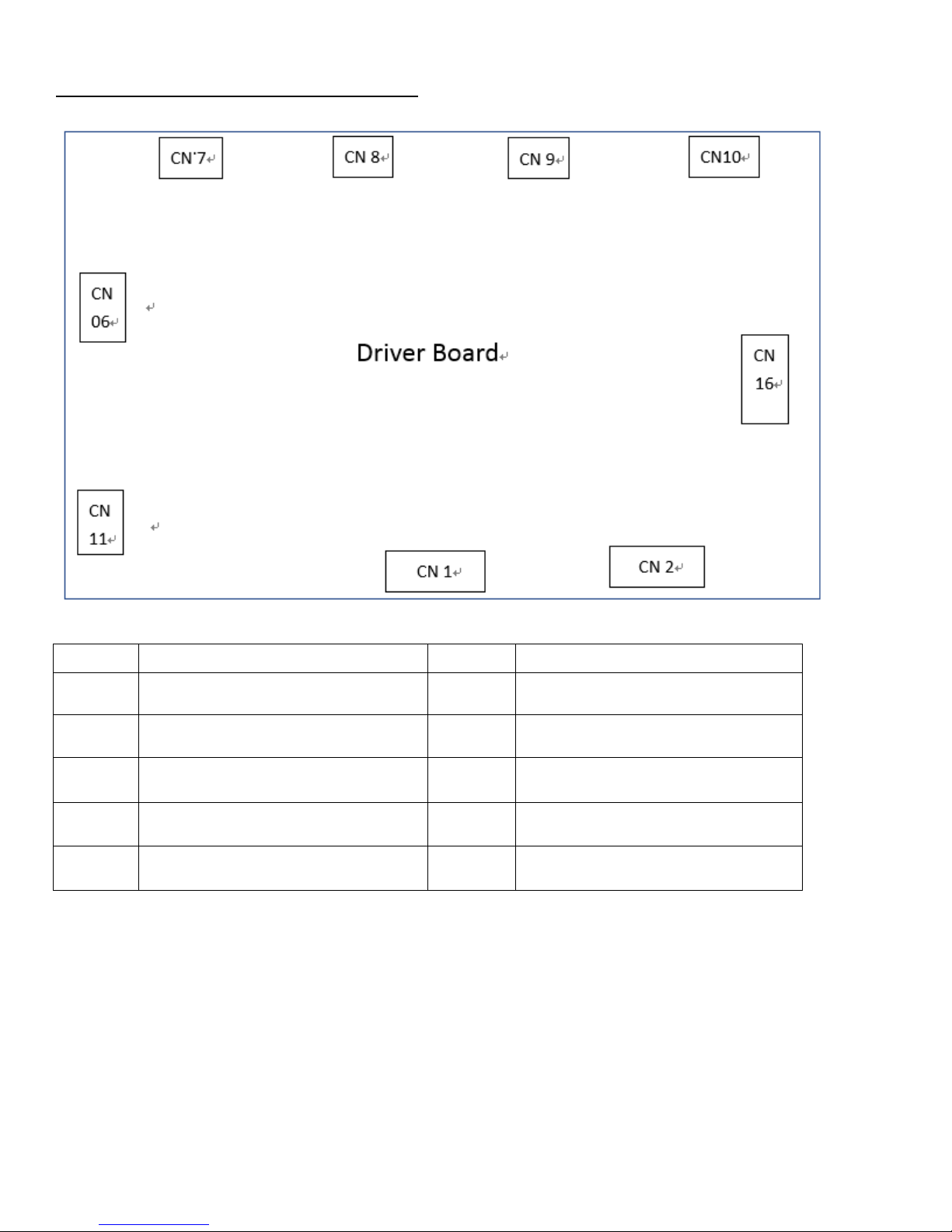
Electric Connections – Driver Board
Connector
Connects to Connector
Connects to
CN1 16-pin, Main Board CN2 CN9 4-pin, Die Module Motor
CN2 10-pin, Main Board CN6 CN10 4-pin, Cutter Motor
CN6 4-pin, 24V DC Power Supply CN11 16-pin, LCD Display
CN7 4-pin, Feed Motor CN16 10-pin, Control Panel Board
CN8 4-pin, Transport Motor
Page 13
- 12 -
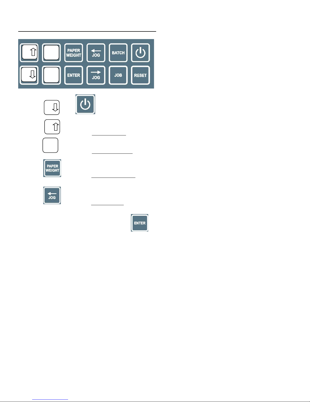
Driver Board Trouble Shooting Procedure
1. Hold and simultaneously for 2 seconds into Burn-in Test Mode
2. Press to activate Feeder Motor, if feed motor does not move, replace driver board
3. Press to activate Transport Motor, if motor does not move, replace driver board
4. Press to activate Die Driving Motor, if motor does not move, replace driver board
5. Press to activate Cutter Motor, if motor does not move, replace driver board
6. Once trouble shooting is complete, press to resume operation.
Up
Dn
Value+
Value-
Dn
Up
Value+
Page 14

- 13 -
Firmware Upgrade
1. Power off
2. Using an adaptor board as shown below:
2.1 10-pin cable to CN 1 on main board and USB connector to USB port on Note Book
3. Power On
Firmware Upgrade Adaptor Board P/N 883-020-051A
4. Detail Procedure
4.1 Go to below website to download the software “Uniflash”
http://processors.wiki.ti.com/index.php/Category:CCS_UniFlash
4.2 Install the software “Uniflash” step by step on your laptop
Page 15

- 14 -
4.3 After install the software Uniflash. Please connect the EVM board (EPROM writer) and target board.
Double click the shortcut icon on the desktop to start.
4.4 “Choose Your Device” at Category “Tiva”
Page 16

- 15 -
4.4 Choose the MCU “TM4C123GH6PZ”
4.6 Choose Your Connection at “Stellaris In-Circuit Debug Interface”
Page 17

- 16 -
4.7 Click “START” to browse the file need to be upgrade.
4.8 Browse the file need to be upgrade.
Page 18
- 17 -
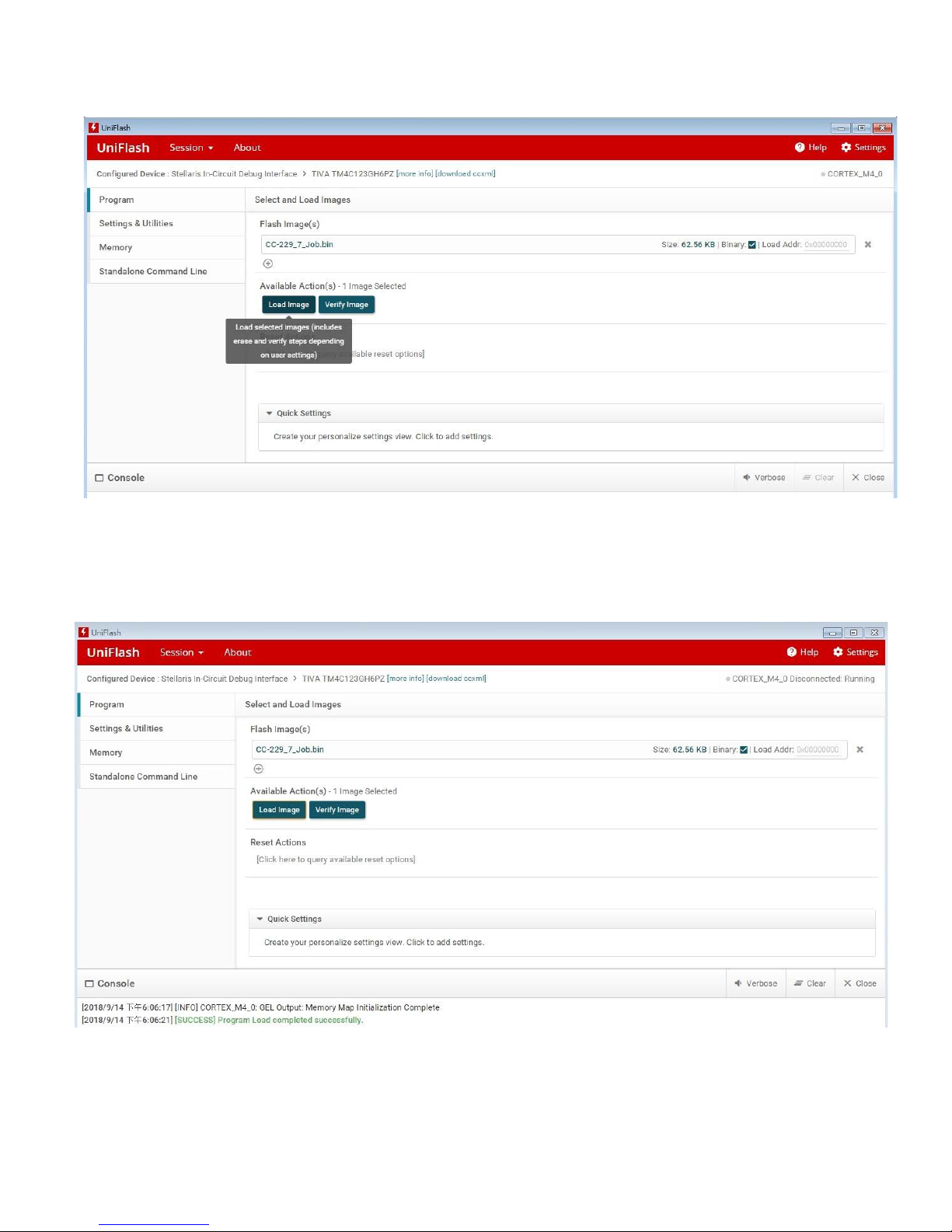
4.9 Click the “Load Image” icon to load the image file to the target board.
4.10 After load the image file successfully. The information line will show “<success>Program Load
completed successfully”. Then you can hear the machine will initialize automatically.
Page 19

- 18 -
Calibrations
1. Hold and at same time for 2 seconds into Calibration mode
2. Press or one time the cursor will be move down or up one factor accordingly
Margin: Top margin
Offset: Last card is too long or to short to compensate
Mark: Cutting Mark
Leng: Card Length
3. The default value is 0, using or to set the number to compensate deviation, the value is –
99~+99.
After calibration is done, press to save.
Dn
Batch
Dn
Up
Value+
Value-
Up
Dn
Value+
Value-
Page 20

- 19 -
Paper Weight
Press into Paper Weight setting mode, then press or to do selection
Setting
Paper Weight
1, 2 120 – 210 (gsm)
3
211 – 300 (gsm)
4, 5 301 – 350 (gsm)
Page 21

- 20 -
Top Margin Parallel Adjustment
1. Power off
2. Remove the rear cover
3. Using a 300gsm or 14 pt. sheet as gauge, rotate the feed roller by hand to feed it into apex of
registration roller firm.
4. Underneath the feed tray has 5.5mm nut to hold the side guide, loosen the nut and align it against the
paper to make it straight. Fasten the nut.
5. Feed a sheet to cut, measure the left and right of the top margin cut is 12.7mm +/- 0.1mm, if not, re
adjust the side guide.
Side
Guide
Fastening
Side
Guide
Fastening
Screw
Page 22

- 21 -
Error Message and Trouble Shooting
Error Message/Symptom Trouble Shooting
Paper Out 1. Feed Tray is empty
2. Check S1 refer to page 8 and 9
3. Is feed motor belt broken? If not,
4. Check pulley screw loose, if not
5. Refer to page 12 to do motor driver trouble shooting
Jam in Sensor 2 1. Check S2 refer to page 8 and 9
2. Adjust the feed tray tension
3. Refer to page 12 to do motor driver trouble shooting
Jam in Sensor 3 1. Check S3 refer to page 8 and 9, if it is OK
2. Replace driver board
Mark Error 1. Check S3 mark/margin sensor refer to page 8 and 9
2. Replace S3 if seeing paper LED is not ON
3. Do mark, top margin calibration
Die Sensor Error 1. Refer to page 8 and 9 and rotate die motor allow index is
seen by S4
2. LED Din 4 needs to be on, if not
3. Replace S4 die index sensor
Top Cover Error 1. Refer to page 8, make sure Din Check top cover interlock
switch
Rear Cover Error Check rear cover interlock switch
Waste Bin Error Check waste bin interlock switch
Finish card not clean and neat 1. Adjust the cutting knife guiding plate, if problem still
2. Replace cutting knife
Finish card length uneven 1. Adjust the cutter Assy. frame mounting screw on the side
plates
2. Check driving belt tension
3. Tighten the compression spring
Cutter Error 1. Driving crane screw loose, if not
2. Check S6, if it is OK
3. Refer to page 12 to do motor driver trouble shooting
Top margin not even left and right 1. Adjust the side guide, make sure it is right angle to the first
set of rollers
Transport no function 1. Check motor pulley screw is loose, If not
2. Check pulley on driving shaft/roller is loose, if not
3. Refer to page 12 to do motor driver trouble shooting
Page 23

- 22 -
Slitting not good Replace the slitter
No Power 1. Check Fuse
2. Check power plug
3. Check main board has 5/24V or power supply has 5/24V
Paper buckled at feed ramp 1. Adjust the feed tray tension spring position
2. Set paper weight according the paper weight
Page 24

- 23 -
Explosive View and WEEE (Fig.1)
NO P/N Name Q’TY
1 883-010-000A
Asm, Side Plate, Non-Operating 1
2
883-020-000A
Asm, Side Plate, Operating
1
3 883-030-000A
Asm, Electric Panel 1
4 883-040-000A
Cover, Front Safety 1
5 883-050-000A
Asm, Feed Table 1
6 881-G00-000A
Bar, Tie 2
7 883-070-000A
Asm, Feed Ramp 1
8 881-N00-000A
Asm, Feed Roller 1
9 881-N10-000A
Asm, Transport Roller, Lowe, Front 1
10
881-N20-000A
Asm, Transport Roller, Lower, Middle 1
11
881-N30-000A
Asm, Transport Roller, Lower, Rear 1
12 881-L00-000A
Asm, Transport Roller, Upper, Front 1
13 881-M00-000A
Asm, Transport Roller, Upper, Rear 1
14 883-140-000A
Asm, Die Skew Adjustment 1
15 883-112-010A
Asm, Dummy Module 1
883-150-000A
Asm, Die Module
Option
16 881-Q00-000A
Asm, Upper Knife Driving 1
17 881-P00-000A
Asm, Lower Knife 1
18 883-180-000A
Asm, Slitter Mounting Chassis 1
19
883-190-000A
Asm, Slitter Alignment 1
20
881-112-0000
Module, Slitter, 2X3.5” 1
21 883-210-000A
Asm, Top, Safety Cover 1
22 883-220-000A
Asm, Cover, Rear 1
23 883-230-000A
Cover, Rear Lower Safety 1
24 00M-000-0003
Magnets 50 * 50 * 12T 1
25 883-250-000A
Asm, Waste Bin 1
Fig. 1
Page 25

- 24 -
Page 26

- 25 -
883-010-000A Non-Operating Side Plate Asm (Fig. 2)
NO P/N Name Q’TY
1 883-010-010A
Side Plate, Right 1
2 00R-000-1101
Rubber Foot 2
NBR
3 00B-000-0905
Angle Bracket 4
4 881-A04-000A
Stopper 1
5 00M-000-0427
Motor, 103H7823-1760 2
6 881-708-0000
Crank, Knife Driving 1
7
881-405-040A
Bushing, OD9, ID6.2 1
8
00B-000-1260
Ball Bearing, L-1260ZZ 1
9
883-010-090A
Idler 1
10 00B-000-1680
Ball Bearing, L-1680ZZ 1
11 00S-000-5904
Standoff, Idler 1
12 00N-000-0012
Nut, D Cut 1
13 883-010-130A
Asm, Rocker Tension Adjustment 3
883-010-131A
Block, Rocker Tension Adj 1
883-010-132A
Holder, Rocker Tension Spring 1
00S-M04-030R
Screw, M4x30 1
14
881-405-070A
Spring, Rocker Tension, Inner 1
00S-000-5611
Spring, Rocker Tension, Outer {Folder Black} 1
15
00G-M10-1912
Gear, M1.0, 19T, OD 12, Idler 1
00B-000-1280
Ball Bearing, L1280ZZ 2
16 881-A13-000A
Stud, Idle Gear 1
17 00E-M08-000E
E-Ring, 8mm 1
18 883-010-180A
Stud, Die Module Bottom Margin 1
19 883-010-190A
Bracket, R, Die Module Mounting Bracket 1
20 02P-17G-0800
Pulley, 0 .2 P, 17G, ID 8 1
21 02P-51G-1700
Pulley, 0 .2 P, 51G, ID 17 1
22
00G-M10-4017
Gear, M1.0, 40T, OD 17 1
23
00B-00R-1760
Ball Bearing, R-1760ZZ
1
24
883-010-230A
Bushing 1
25 00B-MXL-120C
Belt, 0.2P, 120 MXL, 8mm 1
MAR
26 883-010-260A
Case, R, CC-229 1
27
00S-000-6112
Power switch
1
28 00B-0NB-2430
Bushing, Cable Guard 1
Fig. 2
Page 27

- 26 -
Page 28

- 27 -
883-020-000A Operating Side- Side Plate Asm (Fig. 3)
NO P/N Name Q’TY
1 883-020-010A
Side Plate, Left 1
2 00R-000-1101
Rubber Foot 2
NBR
3 00B-000-0905
Angle Bracket 4
4 881-B04-000A
Stopper 1
5 883-020-050A
Main Board 1
883-020-051A
Adaptor Board, Firmware Upgrade 1
6
00M-000-0401
Motor, CKM245-01AH 1
7
02P-17G-0500
Pulley, 0 .2 P, 17G, ID 5.00 1
8
00B-MXL-132C
Belt, 0.2P, 132MXL, 8mm 1
MAR
9 00M-000-0427
Motor, 103H7823-1760 1
10 02P-17G-0800
Pulley, 0 .2 P, 17G, ID 8 1
11 00B-MXL-099C
Belt, 0.2P, 99 MXL, 8mm 1
MAR
12 883-010-090A
Idle Roller 1
13 00B-000-1680
Ball Bearing, L-1680ZZ 1
14 00S-000-5904
Standoff, Idler 1
15 00N-000-0012
Nut, D Cut 1
16
883-020-160A
Asm, Cutting Knife Home Position Sensor 1
00S-00E-ESV3
Sensor, Omron, EE-SV3 1
00W-883-2463
Wire, 24 AWG, 63cm 1
2PH-716-102F
Housing, Female, 2-pin 1
17 883-010-130A
Asm, Rocker Tension Adjustment 3
883-010-131A
Block, Rocker Tension Adj 1
883-010-132A
Holder, Rocker Tension Spring 1
00S-M04-030R
Screw, M4x30, Round Head 1
18 881-405-070A
Spring, Rocker Tension, Inner 1
00S-000-5611
Spring, Rocker Tension, Outer {Folder Black} 1
19
883-010-180A
Stud, Die Module Bottom Margin 1
20
883-020-200A
Asm, Die Home Position Sensor 1
00S-RX6-75NW
Sensor, RIKO RX675-NW 1
00W-883-2463
Wire, 24AWG, 63cm 1
2PH-716-102F
Housing, Female, 2-pin 1
21 883-020-210A
Co v er, RIKO RX675-NW 1
22 883-020-220A
Bracket, L, Die Module Mounting
23
883-020-231A
Asm, Interlock Switch, To p C o ver 1
Page 29

- 28 -
00B-000-0943
Bracket, Interlock Switch Mounting 1
00S-000-6105
Switch, Interlock, 1
00W-883-2233
Wire, 33cm, 22AWG 1
2PH-716-102F
Housing, Female, 2-pin 1
883-020-232A
Asm, Interlock Switch, Rear Cover 1
00B-000-0943
Bracket, Interlock Switch Mounting 1
00S-000-6105
Switch, Interlock 1
00W-883-2257
Wire, 57cm, 22AWG 1
2PH-716-102F
Housing, Female, 2-pin 1
883-020-233A
Asm, Interlock Switch, Waste Bin 1
00B-000-0943
Bracket, Interlock Switch Mounting 1
00S-000-6105
Switch, Interlock, 1
00W-883-2267
Wire, 67cm, 22 AWG 1
2PH-716-102F
Housing, Female, 2-pin 1
24 00C-000-2050
Cover, Interlock Switch 2
25
883-020-250A
Asm, PCB, Control Panel 1
PCBA
26 00D-000-0304
Display, LCD, 4 Row x 20 1
PC/PCBA
27 883-020-270A
Key Pad, CC-229 1
28 883-020-280A
Case, L, CC-229 1
29 00B-0NB-2430
Bushing, Cable Guard, ID24 OD30 3
Fig. 3
Page 30

- 29 -
Page 31

- 30 -
883-030-000A Electric Panel Asm (Fig. 4)
NO P/N Name Q’TY
1 883-030-010A
Plate, Electric Panel, CC-229 1
2
883-030-020A
Power Supply, 24V, RSP-320-24 1
3 00B-PWR-010A
Bracket, Power Supply 4
4 883-030-040A
Driver Board 1
PCBA
5
Cover, Dust, Driver Board 1
Not in Use
Page 32

- 31 -
883-050-000A Feed Tray Asm (Fig. 5)
NO P/N Name Q’TY
1 881-211-000B
Tray, Feed, CC-228 1
2 881-E02-000A
Shaft, Side Guide Sliding 1
3 881-E03-000A
Bracket, Side Guide Mounting
2
4 00S-000-5901
Standoff, 6.35 x 2.2mm
4
5 881-105-000B
Side Guide, Feeder, CC-228
2
6
881-215-000A
Thumb Screw, Feeder Side Guide
2
7
881-406-000A
Shaft, Pivot, Feed Tray
1
8
881-217-000A
Bracket, Feed Tray Mounting
2
9
881-212-000B
Index, Center Alignment
1
10
883-050-100A
Asm, Feed Tray Sensor, CC-229
1
882-101-182A
Bracket, Paper Sensor Mounting
1
883-070-060A
Asm, Paper Sensor 1
00S-00E-ESB5
Sensor, EE-SB5 1
00W-883-2463
Wire, 63cm, 24 AWG 1
2PH-716-102F
Housing, Female, 2-pin
11
00C-000-1210
Collar, OD16, ID10
1
12
881-E12-000A
Nylon Graphite Gasket, OD16, ID10.1
1
Nylon
13
881-E13-000A
Nut, Center Alignment
1
14
881-104-0000
Knob, Center Alignment
1
15
881-E15-000A
Nylon Graphite Gasket, OD21, ID10.2
1
Nylon
16
881-E16-000A
Bushing, Ø10.1 x 2.5
2
POM
17
00C-000-1205
Collar, OD16, ID8(00C-000-1205)
1
18
881-E18-000A
Plate, Pressure Scale
1
19
881-E19-000A
Lever, Pressure Adjustment
1
20
881-E20-000A
Plate, spring Force Adjustment
1
21
881-E21-000A
Bushing, OD12, ID7.5
1
22
881-E22-000A
Plate, Spring
1
23
881-403-000B
Spring, Feed Tray Tension, Outer
1
24
881-403-000C
Spring, Feed Tray Tension, Inner
1
25
881-403-000D
Spring, Lever Tension
1
26
881-103-000B
Plate, Feed Tray Extension
1
27
00S-000-5902
Standoff, 6.35 x 4(00S-000-5902)
2
Page 33

- 32 -
Fig. 5
Page 34

- 33 -
883-070-000A Feed Ramp Asm
NO P/N Name Q’TY
1 881-116-000A
Ramp, Feed 1
881-F01-010A
Plate, Ramp, Feed 1
881-F01-020A
Paper Registration 4
2 00B-000-0905
Angle Bracket 4
3 881-F03-000A
Asm, Separator 1
881-F03-010A
Base, Separator Asm 1
881-F03-020A
Lower Limit Plate, Separator 1
881-F03-030A
Pin, Separator Compression Spring Holding 1
881-F03-040A
Shaft, Pivot, Separator Holding Plate 1
881-F03-050A
Holder, Separator 1
881-F03-060A
Shaft, Pivot, Separator Holder 1
00E-M04-000E
E-Ring M4 2
4
00S-000-1604
Separator, CC-228
1
SEPERATOR MTG 1
POM
SEPERATOR PAD 1
PU
5 881-225-000A
Guide, Feed Ramp
1
6 883-070-060A
Asm, Paper Sensor 1
00S-00E-ESB5
Sensor, EE-SB5 1
00W-883-2463
Wire, 63cm, 24 AWG 1
2PH-716-102F
Housing, Female, 2-pin 1
7
00S-881-0003
Spacer, TXP PLATE 3MM 2
Page 35
- 34 -
Page 36

- 35 -
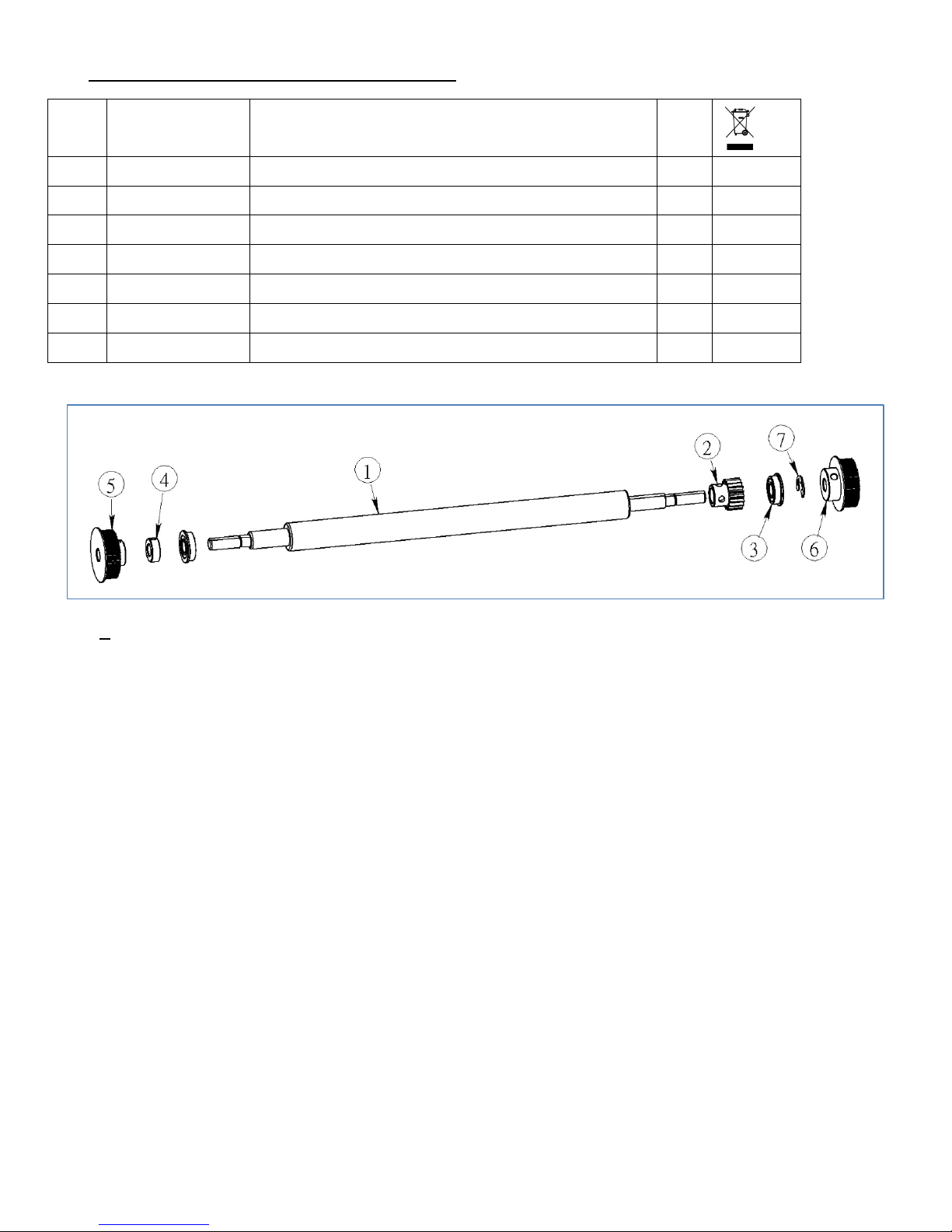
Feed Roller Asm (Fig. 7)
NO P/N Name Q’TY
1 881-N01-000A
Shaft, Feed Roller 1
2 00B-0UF-L001
Pillow Block Ball Bearings, UFL-001 1
3 00R-000-1502
Feed Roller, CC-228 3
881-N03-000A
Core, Feed Roller 1
00R-010-520A
Feed Roller 1
PU
4 881-N04-000A
Shaft, Feed Driving 1
5
162-107-0400
Bushing, OD7, ID6(162-107-0400) 4
6
00B-000-6201
Ball Bearing, 6201ZZ 1
7
881-N07-000A
Housing, Ball Bearing 6201ZZ 1
8 881-N12-000A
Bushing, OD16, ID12.1 1
9 881-N08-000A
Gasket 1
Nylon
10 00A-51G-FC12
Asm, Pulley/Clutch, 51G/FC12 1
02P-51G-180A
Pulley, 0 .2 P, 51G,ID18 1
00O-000-FC12
One Way Clutch, OD18, ID12, FC-12 1
11 00B-000-1209
Hardening Bushing, OD12, ID9(LRT-91216) 1
Fig. 7
Page 37
- 36 -
Front Lower Trasport Roller Asm (Fig. 8)
NO P/N Name Q’TY
1 881-H01-000A
Roller, Transport, CC-228 1
2 00G-M10-1910
Gear, M1, 19T, ID10 1
3 00B-00F-1980
Ball Bearing, LF-1980ZZ 2
4 00C-000-1205
Collar, OD16, ID 8
1
5 02P-51G-08WK
Pulley, 0 .2 P, 51G, ID 8-WK 1
6 02P-51G-080A
Pulley, 0 .2 P, 51G, ID 8 1
7
00E-M08-000E
E-Ring, 8mm 1
Fig. 8
Page 38

- 37 -
Middle Lower Trasport Roller Asm (Fig. 9)
NO P/N Name Q’TY
1 881-H01-000A
Roller, Transport, CC-228 1
2 00G-M10-1910
Gear, M1, 19T, ID 10 1
3 00B-00F-1980
Ball Bearing, LF-1980ZZ 2
4 00C-000-1205
Collar, OD16, ID 8
1
5 02P-51G-08WK
Pulley, 0 .2 P, 51G, ID 8-WK 1
6 00B-MXL-099C
Belt, 0.2P, 99MXL, 8mm 1
MAR
7
00E-M08-000E
E-Ring, 8mm 1
8
00B-MXL-132C
Belt, 0.2P, 132MXL, 8mm 1
MAR
Fig. 9
Page 39

- 38 -
Rear Lower Transport Roller Asm (Fig. 10)
NO P/N Name Q’TY
1 881-H01-000A
Roller, Transport, CC-228 1
2 00G-M10-1910
Gear, M1.0, 19T, ID10 1
3 00B-00F-1980
Ball Bearing, LF-1980zz 2
4 00C-000-1205
Collar, OD16, ID8
1
5 02P-51G-080A
Pulley, 0.2, P51G, ID 8 1
6 00E-M08-000E
E-Ring, 8mm 1
MAR
Fig. 10
Page 40

- 39 -
Front UpperTransort Roller Asm (Fig. 11)
NO P/N Name Q’TY
1 881-L01-000B
Roller, Upper, Transport 1
2 00G-M10-1910
Gear, M1, 19T, ID10 1
3 881-L03-000A
Nylon Graphite Gasket, OD14, ID8.2
1
Nylon
4 883-120-040A
Rocker Asm 2
00H-000-1280
Housing, 1280 Ball Bearing, Transport Rocker 1
00B-00F-1280
Ball Bearing, LF-1280ZZ 1
00B-000-1280
Ball Bearing, L-1280ZZ 1
Page 41

- 40 -
Rear Upper Transnsport Roller Asm (Fig. 12)
NO P/N Name Q’TY
1 881-M01-000B
Roller, Transport 1
2 00G-M10-1910
Gear, M1.0, 19T, ID10 1
3 881-L03-000A
Nylon Graphite Gasket, OD14, ID8.2
1
Nylon
4 883-120-040A
Rocker Asm 2
00H-000-1280
Housing, 1280 Ball Bearing, Transport Rocker 1
00B-00F-1280
Ball Bearing, LF-1280ZZ 1
00B-000-1280
Ball Bearing, L-1280ZZ 1
Fig. 12
Page 42

- 41 -
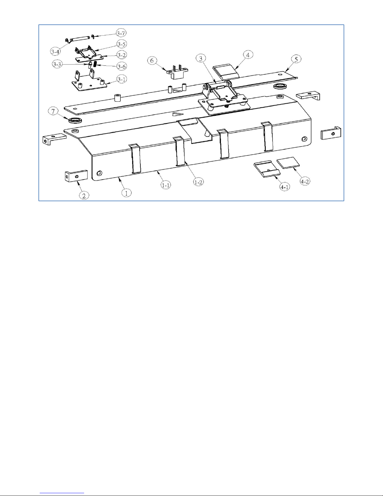
883-140-000A Die Module Fine Tuning Asm (Fig. 13) {Need to add a Mark Reader}
NO P/N Name Q’TY
1 883-140-010A
Bar, Die Module Fine Tuning 1
2 883-140-020A
Bracket, Die Module Sensor Mounting 1
3
883-070-060A
Asm, Paper Sensor
1
00S-00E-ESB5
Sensor, EE-SB5
1
00W-883-2463
Wire, 63cm, 24 AWG 1
2PH-716-102F
Housing, Female, 2-pin 1
4
883-140-040A
Bracket, Die Skew Adjustment 1
5
883-140-050A
Thumb Screw, 1
6
883-14—060A
Nut, Thumb Screw, Skew Adjustment 1
7 00B-0NB-1419
Bushing, NB-1419 1
Fig. 13
Page 43

- 42 -
883-150-000A Die Module (Fig. 14)
NO P/N Name Q’TY
1 883-150-010A
Bracket, Die Module 1
2 883-150-020A
Sie Plate, Die Module 2
3 881-R17-000A
Handle 2
4 883-150-040A
Thumb Screw 2
5 00E-M04-000E
E-Ring M4 5
6 883-150-060A
Bracket, Lower Die Base Mounting 1
7
883-150-070A
Base, Lower Die 1
8
00M-000-0002
Magnet, Rear Cover Position 10
9
883-150-090A
Pin, ψ4*6, Die Plate Positioning
4
10 00B-0LM-06UU
Linear Bearing, LM-06-UU 4
11 883-150-110A
Bar, Upper Die Base Mounting 1
12 883-150-120A
Base, Upper, Die Module 1
13 883-150-130A
Pin, Die Module Sliding 4
14
883-150-140A
Plate, Cam Contact 2
15
883-150-150A
Bracket, Spring Holding 2
16
883-150-160A
Spring,
2
17 883-150-170A
Shaft, Die Module Driving 1
18 883-150-180A
Cam 2
19 00B-000-6005
Ball Bearing, 6005ZZ 2
20 00C-000-4025
Collar, OD 40, ID 25 2
21 00B-00F-6901
Ball Bearing, LF-6901ZZ 2
22 00G-M10-3112
Gear, M1.0, 31T, ID 12 1
23 883-150-230A
Triger 2
24
883-150-240A
Guide Plate 1
25
883-150-250A
Die Plate, Crease, Lower 1
26
883-150-260A
Die Plate, Crease, Upper
1
Fig. 14
Page 44

- 43 -
Page 45

- 44 -
881-Q00-000A Upper Knife Driving Asm (Fig. 15)
NO P/N Name Q’TY
1 881-704-000A
Knife, Upper. CC-228 1
2 881-P02-000A
Plate, Upper KNIFE MOUNTING 2
3 881-719-000A
Link 2
4 881-701-000A
Bushing, OD7.9, ID6.1 2
5 881-P05-000A
Shaft, Knife Driving 1
6 00B-00F-1910
Ball Bearing, LF-1910zz 2
7
881-721-000A
Arm, R, Knife Driving 1
881-P07-010A
Plate, Knife Driving 1
881-P07-020A
Block, Arm Link 1
8 881-720-000A
Arm, L, Knife Driving 1
881-P08-010A
Plate, Knife Driving 1
881-P07-020A
Block, Arm Link 1
9 881-722-000A
Shutter, Index, CC-228 1
10 00E-M10-000E
E-Ring, 10mm 1
11
00C-000-1201
Collar, OD16, ID10
1
12 00B-00R-1560
Ball Bearing, R-1560ZZ 2
13
00B-000-1101
Anti-Static Brush 3” 2
Page 46

- 45 -
881-P00-000A Lower Knife Asm (Fig. 16)
NO P/N Name Q’TY
1 881-711-000A
Chassis, Cutting Knife Mounting CC-229 1
2 881-705-000A
Knife, Lower, CC-228 1
3 881-714-000A
Asm, Middle, Upper Knife Holding Spring 1
881-714-010A
Spring, Middle, Upper Knife Holding Spring 1
881-714-020A
Pin, Middle, Upper Knife Holding Spring 1
881-714-030A
Bushing, Middle, Upper Knife Holding Spring 1
00B-000-L940
Ball Bearing, L940ZZ 2
00E-M04-000E
E-Ring, 4mm 2
4
881-717-000A
Nut, Middle, Upper Knife Holding Spring 1
5 881-715-000A
Asm, Left, Upper Knife Holding Spring 1
881-715-010A
Spring, Left, Upper Knife Holding Spring Asm 1
881-716-020A
Pin, R/L, Upper Knife Holding Spring Asm 1
881-716-030A
Bushing, R/L, Upper Knife Holding Spring Asm 1
00B-000-L940
Ball Bearing, L940ZZ 2
00E-M04-000E
E-Ring, 4mm 2
6 881-716-000A
Asm, Right, Upper Knife Holding Spring 1
881-716-010A
Spring, Right, Upper Knife Holding Spring 1
881-716-020A
Pin, R/L, Upper Knife Holding Spring 1
881-717-030A
Bushing, R/L, Upper Knife Holding Spring 1
00B-000-L940
Ball Bearing, L940ZZ 2
00E-M04-000E
E-Ring, 4mm 2
7 881-718-000A
Nut, L/R Upper Knife Holding Spring Asm 2
8 Not in use
9 883-070-060A
Asm, Paper Sensor 1
00S-00E-ESB5
Sensor, EE-SB5 1
00W-883-2463
Wire, 63cm, 24 AWG 1
2PH-716-102F
Housing, Female, 2-pin 1
Fig. 16
Page 47

- 46 -
Page 48

- 47 -
883-180-000A Slitter Mounting Chassis Asm (Fig. 17)
NO P/N Name Q’TY
1 883-180-010A
Chassis, Slitting Module Mounting , CC-229 1
2 881-S02-000A
Stud, Rear Safety Cover 2
3 00M-000-0002
Magnet, Rear Cover Position 2
4 883-180-040A
Thumb Screw, Slitting Module Fastening CC-229 1
5 881-111-010A
Spring, Compression, Slitting Module Fastening 1
6 00E-M08-000E
E-Ring, 8mm 1
7
00W-M05-000F
FLAT WASHER M5 1
Fig. 17
Page 49

- 48 -
883-190-000A Slitter Left/Right Adj Asm (Fig. 18)
NO P/N Name Q’TY
1 883-190-010A
Nut, Slitter Left/Right Adj 1
2 883-190-020A
Screw, Driving, Slitter Left/Right Adj 1
3 00B-00F-1260
Ball Bearing, LF-1260zz 2
4 00C-000-1606
Collar, OD16, ID 6 1
5 883-190-050A
Block, Slitter Fine Tune Adjustment Holding 1
6 883-190-060A
Ball Steel, Pressure Holding 2
883-190-060B
Spring, Ball Screw Pressure Holding 2
00S-M04-006S
Screw, Set, M4x6 2
7
883-190-070A
Joint, Slitter Fine Tune 1
8 883-190-080A
Clamp, Slitter Joint Locking 1
9 883-190-090A
Knob, Slitter Left/Right Adj 1
10 00E-M06-000E
E-Ring, 6mm 1
Fig. 18
Page 50

- 49 -
Slitter Asm (Fig. 19)
NO P/N Name Q’TY
1 881-801-000A
Chassis, Slitter, 2 x 3.5” 1
881-801-010A
Chassis, Slitter, 5.47X 4.21” 1
2 881-803-000A
Side Plate, L, Slitter 1
881-802-000A
Side Plate, R, Slitter 1
3 881-805-000A
Shaft, Slitter, Lower 1
4 881-804-010A
Shaft, Slitter, Upper, 2x3.5” Slitter 1
881-804-020A
Shaft, Slitter, Upper, 5.47x4.21” Slitter 1
5 881-807-000A
Slitting Wheel, Center Gutter, 0.5” 1
881-807-010A
Slitting Wheel, Center Gutter, 6mm 1
881-807-020A
Slitting Wheel, Center Gutter, 0.25” 1
881-807-030A
Slitting Wheel, Center Gutter, 3mm 1
6 881-808-000A
Slitting Wheel, Side Trim 2
7 881-827-000A
O Ring, JASO 2027 3
PU
8 881-810-000A
Roller, Ejection Driving, Slitter 2
POM
9 881-115-000A
Belt, Transport, Slitter 2
PU
10 881-809-020A
Roller, Transport, Slitter 4
11 881-806-000A
Slitting Wheel, Upper, CC-228 4
12 00B-00F-6901
Ball Bearing, F6901ZZ 4
13 00E-M10-E000
E-Ring, 10mm 2
14
00G-M10-3112
Gear, M1.0, 31T, ID12 2
15
881-812-000A
Deflector, Side Waste, 0.5” 2
881-812-000A
Deflector, Center Gutter, 0.5” 1
881-812-010A
Deflector, Center Gutter, 0.25” 1
881-812-020A
Deflector, Center Gutter, 6mm 1
881-812-030A
Deflector, Center Gutter, 3mm 1
16 881-114-000A
Asm, Upper Ejection Roller 2
881-114-010A
Roller, Upper, Ejection 2
POM
881-114-020A
Spring, Upper Ejection Roller 2
881-114-030A
Pin, Upper Ejection Roller 2
00E-M03-E000
E-Ring, M3 4
17
881-113-000A
Roller, Lower, Ejection 2
POM
881-113-010A
Pin, Lower Ejection Roller 2
00E-M03-E000
E-Ring, M3 4
18 881-R17-000A
Handle 1
Page 51

- 50 -
Fig. 19
Page 52

- 51 -
883-021-000A Top, Safety Cover Asm (Fig. 18)
NO P/N Name Q’TY
1 883-021-010A
Top, Safety Cover 1
2 883-021-020A
Bracket, Top Cover 2
3 883-021-030A
Trigger, Top Cover 1
Fig. 18
Page 53
- 52 -
Rear, Safety Cover Asm 883-220-000A (Fig. 19)
NO P/N Name Q’TY
1 883-220-010A
Rear, Safety Cover , CC-229 1
2 883-220-020A
Catcher
1
3 881-109-1000
Asm, Divider 1
881-109-1000-0A
Plate, Divider 1
881-109-1000-0B
Flexible Magnets 75 * 18 1
Fig. 19
Page 54

- 53 -
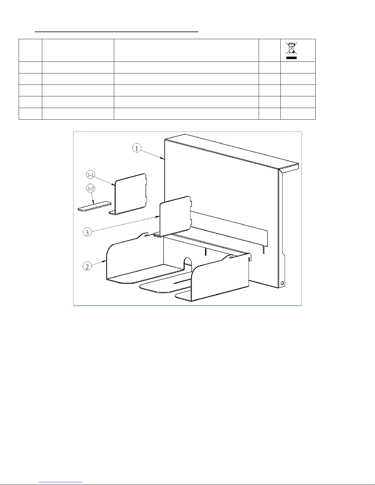
Waste Bin Asm 883-250-000A (Fig. 20)
NO P/N Name Q’TY
1 883-250-010A
Waste Bin , CC-229 1
2 00A-000-220A
Index, Waste Bin 1
3 881-R17-000A
Handle 1
Fig. 20
Page 55

- 54 -
Recommended Spare Parts List
Part Number Name
00A-51G-FC12 Asm, Pulley/Clutch, 51G/FC12
00B-000-1209
Hardening Bushing, OD12, ID9(LRT-91216)
00B-0UF-L001 Pillow Block Ball Bearings, UFL-001
00B-MXL-099C Belt, 0.2P, 99 MXL, 8mm
00B-MXL-132C Belt, 0.2P, 132MXL, 8mm
00D-000-0304 Display, LCD, 4 Row x 20
00M-000-0401 Motor, CKM245-01AH
00M-000-0427
Motor, 103H7823-1760
00S-000-1604 Separator, CC-228
00S-000-5611 Spring, Rocker Tension, Outer {Folder Black}
00S-000-6105
Switch, Interlock,
02P-17G-0500 Pulley, 0 .2 P, 17G, ID 5
02P-17G-0800 Pulley, 0. 2 P, 17G, ID 8
02P-51G-080A
Pulley, 0 .2 P, 51G, ID 8
02P-51G-08WK Pulley, 0 .2 P, 51G, ID8-WK
881-403-000B
Spring, Feed Tray Tension, Outer
881-403-000C
Spring, Feed Tray Tension, Inner
881-403-000D
Spring, Lever Tension
881-405-070A Spring, Rocker Tension, Inner
881-704-000A
Knife, Upper. CC-228
881-705-000A Knife, Lower, CC-228
881-714-000A Asm, Middle, Upper Knife Holding Spring
881-715-000A Asm, Left, Upper Knife Holding Spring
881-716-000A Asm, Right, Upper Knife Holding Spring
881-H01-000A Roller, Transport, CC-228
881-L01-000B
Roller, Upper, Transport
881-M01-000B Roller, Transport
883-010-260A Case, R, CC-229
883-020-050A Main Board
883-020-051A Adaptor Board, Firmware Upgrade
883-020-160A Asm, Cutting Knife Home Position Sensor
883-020-200A
Asm, Die Home Position Sensor
883-020-250A
Asm, PCB, Control Panel
883-020-270A Key Pad, CC-229
883-020-280A Case, L, CC-229
Page 56

- 55 -
883-030-020A Power Supply, 24 V, RSP-320-24
883-030-040A Driver Board
883-050-100A
Asm, Feed Tray Sensor, CC-229
883-070-060A Asm, Paper Sensor
883-112-010A Asm, Dummy Die Module
883-120-040A Rocker Asm
883-150-000A Asm, Die Module
883-150-250A Die Plate, Crease, Lower
883-150-260A Die Plate, Crease, Upper
 Loading...