

Page 1

Duplo DF-1000 Air
Suction Paper Folder
Instruction Manual
Page 2
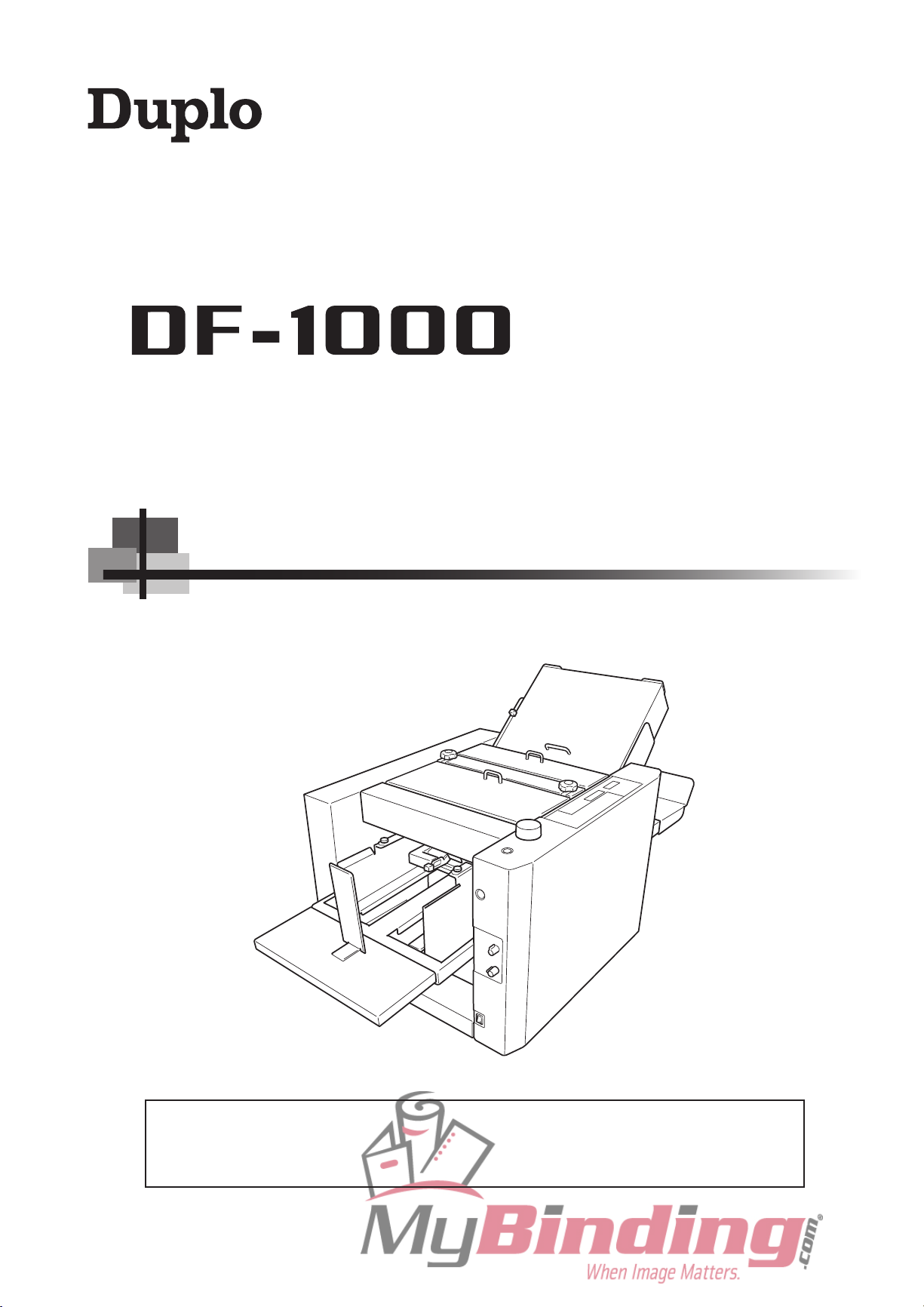
AIR SUCTION PAPER FOLDER
[220 to 240 V]
INSTRUCTION MANUAL
Be sure to read this manual prior to use.
Please leave this manual at the site of use for easy reference.
Page 3
DECLARATION OF CONFORMITY
DUPLO CORPORATION, located at 1-6, Oyama 4-chome, Sagamihara-shi, Kanagawa-ken 229-1180, Japan, declares
that the following product,
Name of product : Air Suction Paper Folder
Models : DF-1000
complies with the provisions defi
Regulation : Low Voltage Directive 73/23/EEC under IEC60950-1:2001 including EN60950-1:2001 deviations.
Electromagnetic Compatibility Directive 89/336/EEC under EN55011:1998 + A1:1999 + A2:2002,
EN55014-2:1997 + A1:2001, EN61000-3-2:2000, EN61000-3-3:1995 + A1:2001.
ned by the regulations listed below.
En
KONFORMITÄTSERKLÄRUNG
Die DUPLO CORPORATION mit Sitz in 1-6, Oyama
4-chome, Sagamihara-shi, Kanagawa-ken 229-1180,
Japan, erklärt hiermit, dass das folgende Produkt,
Bezeichnung des Produkts :
Luftsaugen Papierfaltmaschine
Modell :
DF-1000
den nachfolgend aufgelisteten Richtlinien entspricht :
Richtlinien :
N i e d e r s p a n n u n g s r i c h t l i n i e 7 3 / 2 3 / E W G un t e r
IEC60950-1:2001 und EN60950-1:2001 Abweichungen.
Richtlinie über die elektromagnetische Verträglichkeit
89/336/EWG unter EN55011:1998 + A1:1999 + A2:2002,
EN5 501 4-2 :199 7 + A 1:20 01, EN6 100 0-3- 2:2 000 ,
EN61000-3-3:1995 + A1:2001.
Ge
DECLARATION DE CONFORMITE
DUPLO CORPORATION, située à 1-6, Oyama 4-chome,
Sagamihara-shi, Kana gaw a-k en 2 29- 118 0, Japon,
déclare que le produit suivant ;
Nom du produit :
L’air sucent la plieuse de papier
Modèle :
DF-1000
DICHIARAZIONE DI CONFORMITÁ
DUPLO COPRORATION sita a 1-6, Oyama 4-chome,
Sagamihara-shi, Kanagawa-ken 229-1180 Japan, dichiara
che il seguente prodotto,
Nome del prodotto :
L’aria succhia il macchina piegantesi di carta
Modello :
DF-1000
è conforme ai requisiti definiti dalle norme sotto elencate.
Direttiva Bassa Tensione :
Direttiva relativa alle apparecchiature a bassa tensione
73/23 / C E E i n bas e a I E C 6 0 950-1: 2 0 0 1 inc l u s o
EN60950-1:2001 deviazioni.
Direttiva EMC 89/336/CEE in base a EN55011:1998
+ A1:1999 + A2:2002, EN55014-2:1997 + A1:2001,
EN61000-3-2:2000, EN61000-3-3:1995 + A1:2001.
It
DECLARACIÓN DE CONFORMIDAD
DUPLO CORPORATION, con domicilio en 1-6, Oyama
4-chome, Sagamihara-shi, Kanagawa-ken 229-1180
Japan, declara que el producto siguiente :
Nombre del producto :
Succión del aire máquina que dobla de papel
Modelos :
DF-1000
e s t c o n for m e a u x di s p osi t i o n s dé f i n i e s pa r l e s
réglementations suivantes ;
Réglementations :
Directive sur la basse tension 73/23/EEC en application
de IEC60950-1:2001 et EN60950-1:2001 derogations.
Directive de compatibilité électromagnétique 89/336/
EEC d’après EN55 011:1998 + A1:1999 + A2:2002,
EN5 501 4-2 :199 7 + A 1:20 01, EN6 100 0-3- 2:2 000 ,
EN61000-3-3:1995 + A1:2001.
Fr
Cumple las disposiciones definidas por las siguientes
reglamentaciones :
Reglamentaciones :
D i re c t i v a s o b r e ba j a t e n s i ó n 7 3 / 2 3 / C E E b a j o
IEC60 9 5 0 - 1:2001 inclu y e n d o la s d e r o gacion e s
EN60950-1:2001.
Directiva sobre CEM 89/336/CEE bajo EN55011:1998
+ A1:1999 + A2:2002, EN55014-2:1997 + A1:2001,
EN61000-3-2:2000, EN61000-3-3:1995 + A1:2001.
Sp
Page 4

INTRODUCTION
Thank you for purchasing a Duplo product.
Be sure to read this manual prior to using the product.
After reading, leave the manual at the site of use for easy reference whenever questions
related to the product arise in the future.
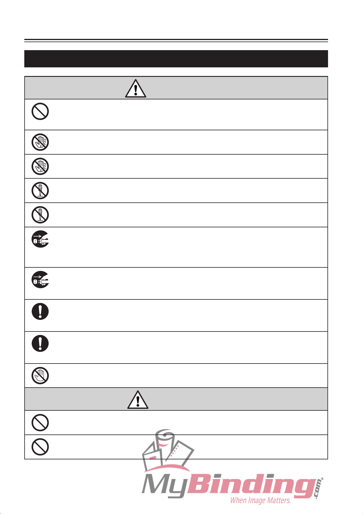
Symbols
In this manual, several symbols are used to indicate important warnings. Please make sure
to read instructions accompanied by these symbols. These symbols have the following
meanings.
Describes instructions which must be followed in use.
Be sure to read the instructions to avoid problems due to incorrect operations.
Describes restrictions in operations.
Be sure to read to make full use of the functions of this product.
Describes names of related items and supplementary instructions.
i
Page 5
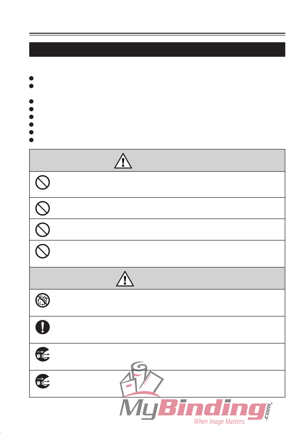
SAFETY PRECAUTIONS
In this manual, operations and handling of the unit which are hazardous are described using
the following marks to prevent personal injury or property damage to the user and others.
Ignoring this mark could result in the possibility of
WARNING
serious injury or even death.
Ignoring
CAUTION
This mark indicates a “Warning” or “Caution”.
A graphic may be shown inside the mark to describe the warning or caution more specifically.
This mark indicates a forbidden action.
A graphic may be shown inside the mark to describe the forbidden action more specifically.
This mark indicates actions that must be performed.
A graphic may be shown inside the mark to describe the action to be performed more specifically.
or physical damage.
this mark could result in the possibility of injury
Power Supply
This unit shall be installed near the socket-outlet where the plug on the power supply cord is
easily accessible.
Make sure the power supply used is always within the following range.
Power supply : 100 to 240 V AC, 50/60 Hz
When you power other appliances from the same AC outlet, make sure that the combined
power consumption does not exceed the power supply capacity.
Rated current (Rated power) : 2 to 1 A (140 W)
WARNING
Use only the power supply voltage specified on the main nameplate.
Using other voltages could result in a fire or an electrical shock.
Make sure that the combined power consumption of the appliances to be
connected does not exceed the capacity rating of the power outlets or plug
receptacles.
Exceeding the capacity rating could cause the power outlets, plug receptacles, or power extension
cords to overheat and catch a fire.
ii
Page 6
SAFETY PRECAUTIONS
Operating Environment
Operate this unit in the following environment.
where the temperature range is between 5 and 35°C (–10 to +50°C in storage)
where the humidity range is between 20 and 80% RH (10 to 90% RH in storage, however
no condensation)
which is not subject to direct sunlight
which is reasonably free from dust
which is subject to little or no vibration
which is free from air-borne salt
where there are no harmful chemicals
where the unit is not exposed to water
WARNING
Keep this unit and the power cord away from heaters and heater vents.
Excessive heat could melt the cover or power cord covering, and result in a fire or an electrical
shock.
Do not place metal objects or vessels containing liquids on top of the unit.
The entry of any metal object or liquid could result in a fire or an electrical shock.
Do not insert any metal or easily-combustible object inside this unit.
This could result in a fire or an electrical shock.
Do not use flammable sprays inside or near the unit (e.g. when cleaning the
unit).
Such flammable gas may ignite and cause a fire or combustion.
CAUTION
Do not install this unit in a location where there is excessive humidity or
where contact with water is possible.
Poor choice of location could result in deterioration of the insulation, a fire or an electrical shock.
Install this unit on a level, stable stand or floor, with sufficient space around
it.
Failure to do so could result in the unit overturning and causing injury.
Disconnect the power plug from the power outlet before attempting to move
this unit.
Failure to do so could result in power cord damage, a fire or an electrical shock.
Always disconnect the power plug from the power outlet when the unit is not
to be used for an extended period.
Failure to do so could result in a fire due to leakage current if the insulation should deteriorate.
iii
Page 7
SAFETY PRECAUTIONS
Maintenance, etc.
Do not damage the power cord or power plug.
Do not scratch, alter, bend, twist, pull or place heavy objects on the power cord or power plug.
This could result in damage, a fire or an electrical shock.
Do not handle the power plug with wet hands.
This could result in an electrical shock.
Do not touch the power switch with wet hands.
Otherwise electric hazards may occur.
Do not remove the cover or back panel.
This unit contains high-voltage components that could cause an electrical shock.
WARNING
Do not disassemble, modify or repair this unit.
There is a danger of fire, electrical shock or injury. Contact your dealer when repairs are necessary.
If any foreign object such as metal or liquid should enter this unit,
immediately turn the unit off at the power switch and disconnect the power
plug from the power outlet.
Failure to do so could result in a fire or an electrical shock. Contact your dealer immediately.
Before cleaning this unit, turn the unit off at the power switch and
disconnect the power plug from the power outlet.
Accidental operation of the unit during cleaning could result in injury.
Remove any dust that accumulates on the power plug prongs and the
surface of the plug from which the prongs extend.
Accumulated dust could result in a fire.
Always grip the plug when disconnecting the power plug from the power
outlet.
Forcibly pulling on the power cord could cause damage, resulting in a fire or an electrical shock.
Do not touch or insert foreign objects into any rotating part during operation.
This could result in injury.
iv
CAUTION
Keep away long hair, ties, jewelry and loose clothing.
This could result in injury.
Do not put fingers inside during operation.
This could result in injury.
Page 8

Caution Label Location
SAFETY PRECAUTIONS
v
Page 9

TABLE OF CONTENTS
Chapter 1
Before Operation
1. Names and Operation of Parts ........1-2
2. Names and Operation of Control
Panel ..................................................1-6
3. Description of LCD ...........................1-7
4. Handling of Paper
4-1. Paper Used ..................................... 1-8
4-2. Precautions on Stacking Paper
.............................1-8
...... 1-9
Chapter 2
Basic Operation
1. Standard Folding of Standard
Paper .................................................2-2
1-1. Standard Paper .............................. 2-2
1-2. Standard Folding Modes
1-3. Operation Procedure
................ 2-2
...................... 2-3
Chapter 4
Troubleshooting
1. Correcting Folding Misalignment ...4-2
1-1. Correcting Folding Misalignment
Along Sides of Paper
1-2. Correcting Folding Misalignment
Along Vertical Length of Paper
1-3. Correcting Deformed Folding
2. Adjusting the Stacker Roller ...........4-13
2-1. Changing the Stacker Roller
Position
2-2. Changing the Stacker Roller
Height
........................................... 4-13
............................................. 4-14
3. When Paper Jamming Occurs ........4-15
3-1. When Paper Jams at
Paper Feed Tray ............................. 4-15
3-2. When Paper Jams Inside Unit
3-3. When Paper Jams at
Stacker Unit .................................... 4-18
...................... 4-2
....... 4-5
......... 4-12
........ 4-15
Chapter 3
Applied Use
1. Standard Folding of
Non-standard Paper .........................3-2
1-1. Paper Size Restrictions .................. 3-2
1-2. Operation Procedure
2. Custom Folding ................................3-5
2-1. Paper Size Restrictions .................. 3-5
2-2. Operation Procedure
3. Using Special Paper .........................3-8
3-1. Art Paper, Coated Paper ................ 3-8
3-2. Recycled Paper
3-3. B6 Size Paper ................................. 3-10
4. Function Setting Mode .....................3-11
4-1. Non-standard Paper Length
Setting ............................................ 3-11
4-2. Operation Mode Setting
4-3. Interval Setting ................................ 3-15
4-4. Separating Air Strength Setting
4-5. Paper Feed Interval Setting
4-6. Stacking Amount Setting
4-7. Stacker Belt Setting ........................ 3-20
4-8. Thick Paper Stopper Correction
Setting ............................................ 3-21
...................... 3-2
...................... 3-5
.............................. 3-9
.................. 3-12
...... 3-17
............ 3-18
................ 3-19
4. Error Messages ................................4-19
4-1. Paper Jam Messages ..................... 4-19
4-2. Operation Error Messages
4-3. Key Input Error Messages .............. 4-21
4-4. Motor and Sensor Error
Messages
....................................... 4-21
............. 4-19
5. Troubleshooting ...............................4-24
Chapter 5
Maintenance
1. Cleaning the Unit ..............................5-2
1-1. Cleaning the Folding Rollers .......... 5-2
1-2. Cleaning the Suction Belts
1-3. Cleaning the Stacker Belts
1-4. Cleaning the Paper Sensor
1-5. Cleaning the Paper Feed Inlet
Sensor ............................................ 5-5
1-6. Cleaning the Paper Ejection Outlet
Upper Sensor
1-7. Cleaning the Paper Ejection Outlet
Lower Sensor
................................. 5-6
................................. 5-6
............. 5-4
............. 5-4
............ 5-5
Appendix
1. Specifications ...................................A-2
vi
Page 10

Chapter 1
BEFORE OPERATION
1-1
Page 11

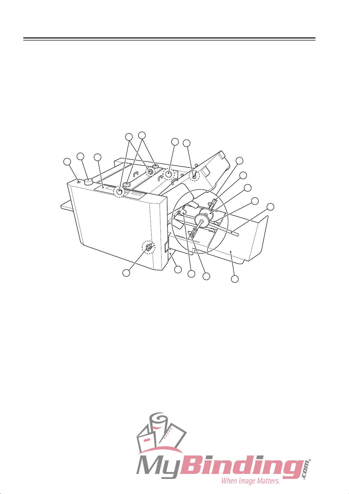
1. NAMES AND OPERATION OF PARTS
13
14
15
11
16
12
7
10
9
8
2
5
6
3
4
1
17
21
20
19
18
1-2
Page 12
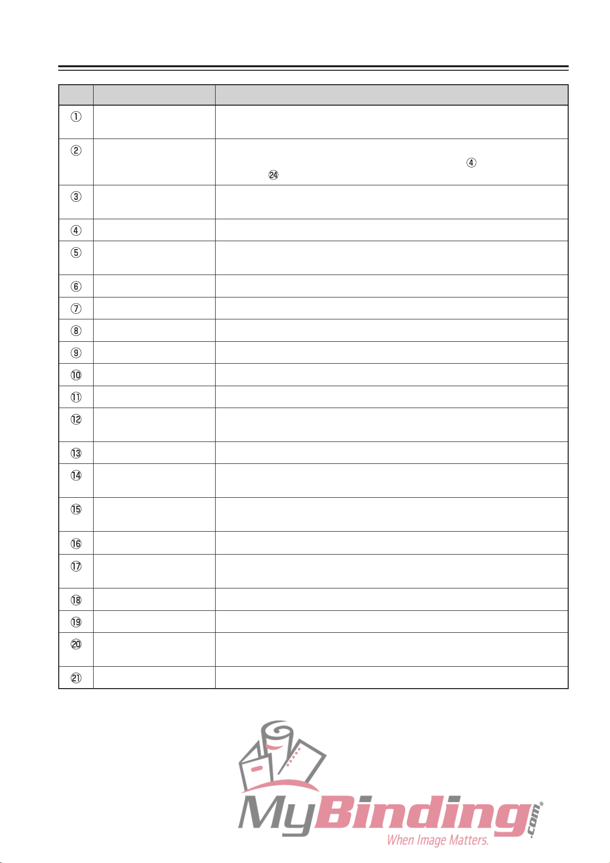
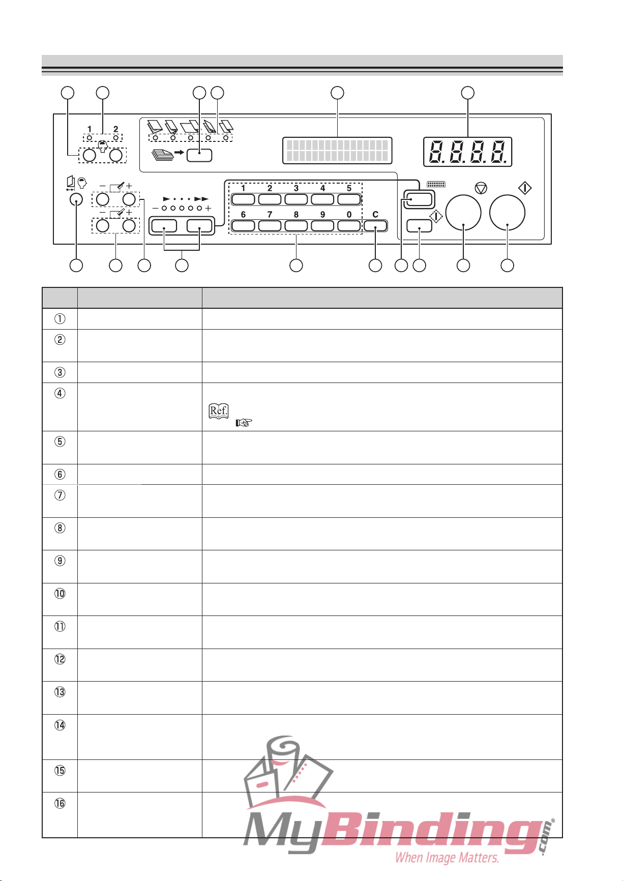
1. NAMES AND OPERATION OF PARTS
No. Name Operation
Folding plate Guide plate for deciding the paper folding position. Composed of folding
plates 1 and 2.
Top cover L When paper is jammed at the paper feed section, open this cover to
remove the paper. Also open this cover to use the Skew correction
knob and Skew roller spring pressure adjusting knob.
Top cover R When paper is jammed at the folding roller section, open this cover to
remove the paper.
Skew correction knob For correcting skewed paper feed. Located inside the top cover L.
Side guide adjusting
knob
Side guide Holds the left and right of the paper stacked on the paper feed tray.
Paper feed tray For stacking paper
Auxiliary paper feed tray Supports the rear of the paper.
Rear guide Holds the trail edge of paper stacked on the paper feed tray.
Power cord inlet For connecting the power cord
Power switch For turning on/off the power
Level sensor adjusting
lever
Tray down button For lowering the paper feed tray
Separating air adjusting
knob
Separator adjusting
knob
For correcting the direction of the side guide (paper feed direction)
For adjusting the gap between the paper and suction belt
For adjusting the amount of separating air
For adjusting the height of the separator
Safety lever Prevents hand from getting caught when the paper feed tray is descending.
Separating-air duct Blows out air for separating paper stacked on the paper feed tray. (3
locations)
Separator Prevents double-feed.
Suction belt Sucks and conveys paper.
Shutter Adjusts the amount of separating air blown out. Linked to the separator
adjusting knob.
Level sensor Determines the height of the paper floated by separating air.
1-3
Page 13
1. NAMES AND OPERATION OF PARTS
32
30
34
31
23
38
22
26
27
37
36
33
35
24
25
29
28
1-4
Page 14
1. NAMES AND OPERATION OF PARTS
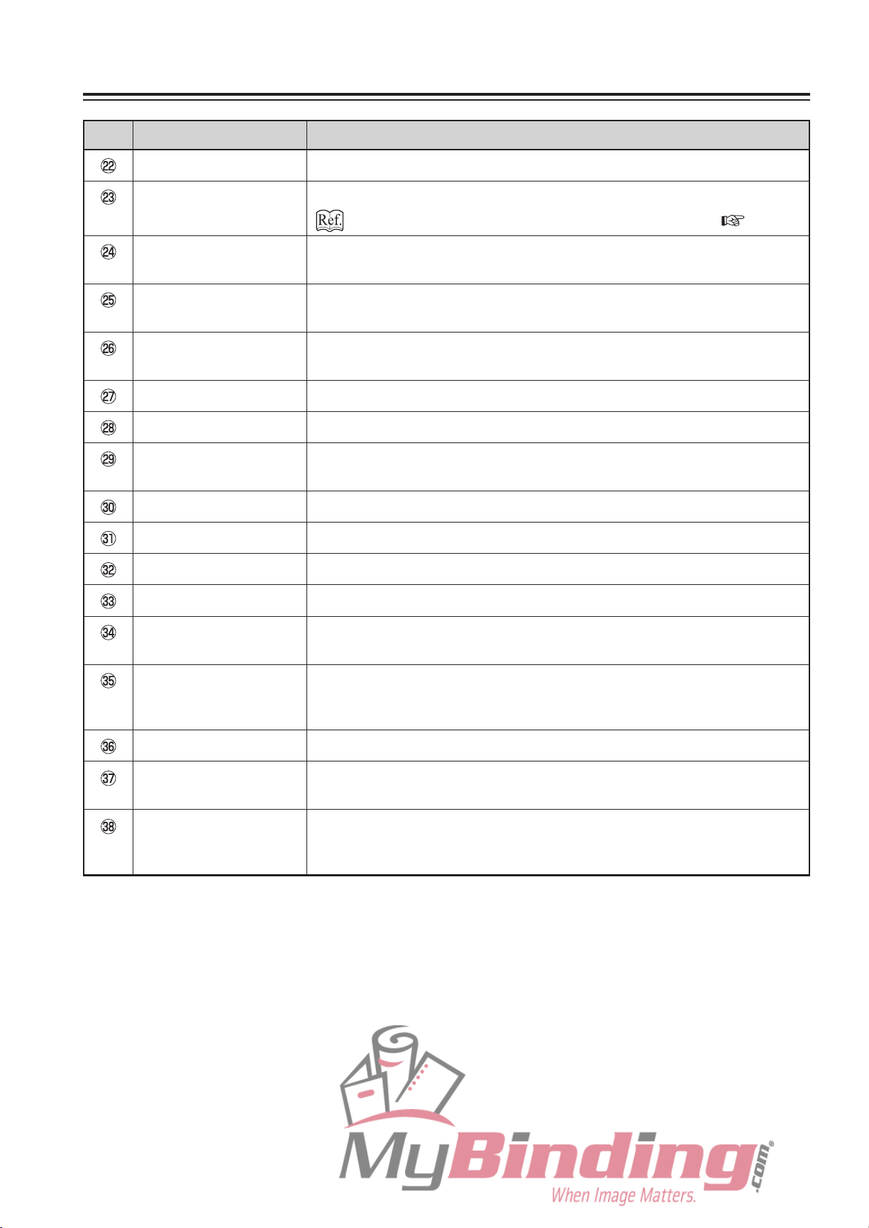
No. Name Operation
Side guide dial Turn this dial to move the side guide.
Control panel For operating the unit
“2. NAMES AND OPERATION OF CONTROL PANEL” ( p.1-6)
Skew roller spring
pressure adjusting knob
Skew roller fixing knob Loosen this knob to use the skew correction knob. Be sure to tighten it after
Jam correction knob For rotating the folding rollers when paper has jammed inside the unit or
Folding plate connector For connecting the folding plate and the main body
Stacker unit connector For connecting the stacker unit and the main body
Stacker unit Composed of the stacker roller, stacker belt, and stacker support for
Stacker roller For receiving folded paper and aligning the paper
Stacker belt For ejecting folded paper to the paper receiving tray
Stacker support For supporting the stacker roller
Lever For changing the height of the stacker roller
Auxiliary paper ejection
guide
For switching the roller spring pressure when folding misalignment occurs.
Normally, use at the “bottom” position. Located inside the top cover L.
adjustments.
when cleaning the unit
ejecting folded paper to the paper receiving tray.
When alignment of the ejected paper is poor, hook to the shaft of the
stacker roller.
Paper ejection guide Helps guide folded paper onto the stacker unit. Remove if paper jams
frequently at the stacker roller, or when it is difficult to remove jammed
paper.
Paper receiving tray For receiving folded paper from the stacker unit
Side cover When paper jams during paper ejection, open this cover to remove the
paper.
Thin paper feed button Switch this button according to the paper thickness. Set to ON when using
fine quality paper less than 81.4 g/m2.
(Lamp lit: ON, lamp is off: OFF)
1-5
Page 15
2. NAMES AND OPERATION OF CONTROL PANEL
11 13
10
12
14 15 16
7 35 2 1489 6
No. Name Operation
Start key Press to start paper folding.
Stop key Press to stop paper folding. Pressing this key at the function setting mode
screen registers that setting.
Test key Press to test fold two sheets of paper.
Mode key Press to switch the function setting mode.
Chapter 3 APPLIED USE “4. FUNCTION SETTING MOD E”
( p.3-11)
Clear key Press to change or erase the number of sheets to be processed or paper
length entered.
Numerical keys (0 to 9) Press to enter the number of sheets to be processed or paper length.
Speed key Press to select the processing speed from five levels (Speed 1 to 5).
When the power is turned on, the speed used the last time is displayed.
Folding plate 1 folding
stopper adjusting key
Folding plate 2 folding
stopper adjusting key
Adjustment registration
key
Custom folding
registration key
Custom folding
registration lamp
Press to adjust the position (folding position) of the folding stopper of
folding plate 1.
Press to adjust the position (folding position) of the folding stopper of
folding plate 2.
If the position of the folding stopper has been finely adjusted in standard
folding operations, the adjustment value can be registered with this key.
Press to register the position of the folding stopper and stacker roller which
have been moved when using custom folding modes.
When this lamp is lit, it means that the custom folding mode is registered.
Folding mode key Press to select the folding mode from five standard folding modes. If the
Standard folding lamp Displays the folding mode selected from five standard folding modes.
Liquid crystal display
(LCD)
Numerical display
(Counter)
1-6
custom folding mode is registered, use this key to select it.
When a f old ing mode reg ist ered wit h the fol din g sto ppe r pos iti on
adjustment value is selected, the corresponding lamp blinks.
Displays the size of standard paper stacked on the paper feed tray (A3 to
B6), paper length registered, and error messages.
When using the add count mode, displays the number of sheets processed.
When using the subtract count mode, displays the number of sheets left to
be processed.
Page 16
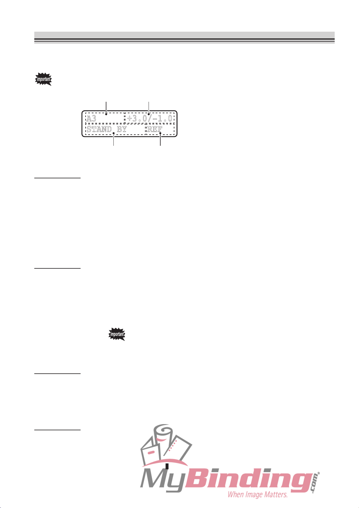
3. DESCRIPTION OF LCD
The LCD displays standard paper size, various registration data, operation modes, operation
states, and error messages, etc.
The backlight of the LCD will go off automatically if the unit is not used for a certain
period of time.
A area B area
A .0/- .0
AN Y
C area D area
This LCD example shows the standard folding of
standard paper when set to the last time fold mode.
(1) A area
Standard paper size : Six types: A3, B4, A4, B5, A5, and B6
Registration data : When the length of non-standard paper is registered, the length will be
displayed (182 to 432 mm).
Operation mode
Folding mode :
When set to the folding stopper fixed mode, “FIX” will be displayed.
:
When set to the custom folding mode, “CF-1” or “CF-2” will be
displayed.
(2) B area
Registration data : The correction value of the folding stopper position of folding plates 1
and 2 will be displayed as “±∗.∗ / ±∗.∗” (unit: mm). As folding plate 2 is
not used in single folding, “±∗.∗ / ...” (unit: mm) will be displayed.
In custom folding, the folding stopper position of folding plates 1 and 2
will be displayed as “
When the operation mode is set to folding stopper fixed mode,
the folding stopper position displayed will be the same as custom
folding.
∗∗∗.∗
∗∗∗.∗
/
” (unit: mm).
(3) C area
Operation status : “WAIT”, “STAND BY”, “PROCESSING”, “TEST RUN”
Error message :
The place of paper jam or malfunction, and details of operation error,
etc. will be displayed.
(4) D area
Operation mode : When set to the last time fold mode, “REF” will be displayed.
When set to the interval function, “I” will be displayed.
W h e n t h e t h i c k p a p e r s t o p pe r c o rr ec t i o n s e t t in g i s s e t to
“CORRECTED”, “ ” will be displayed.
1-7
Page 17
4. HANDLING OF PAPER
4-1. Paper Used
If using folded or curled paper, flatten first prior to use.
Make sure that the printing ink on the paper has dried completely prior to use.
If used without the ink completely dried, the folding roller or paper may become dirty.
Use paper that has been cut at right angles.
If not cut at right angles, problems such as folding misalignment may occur.
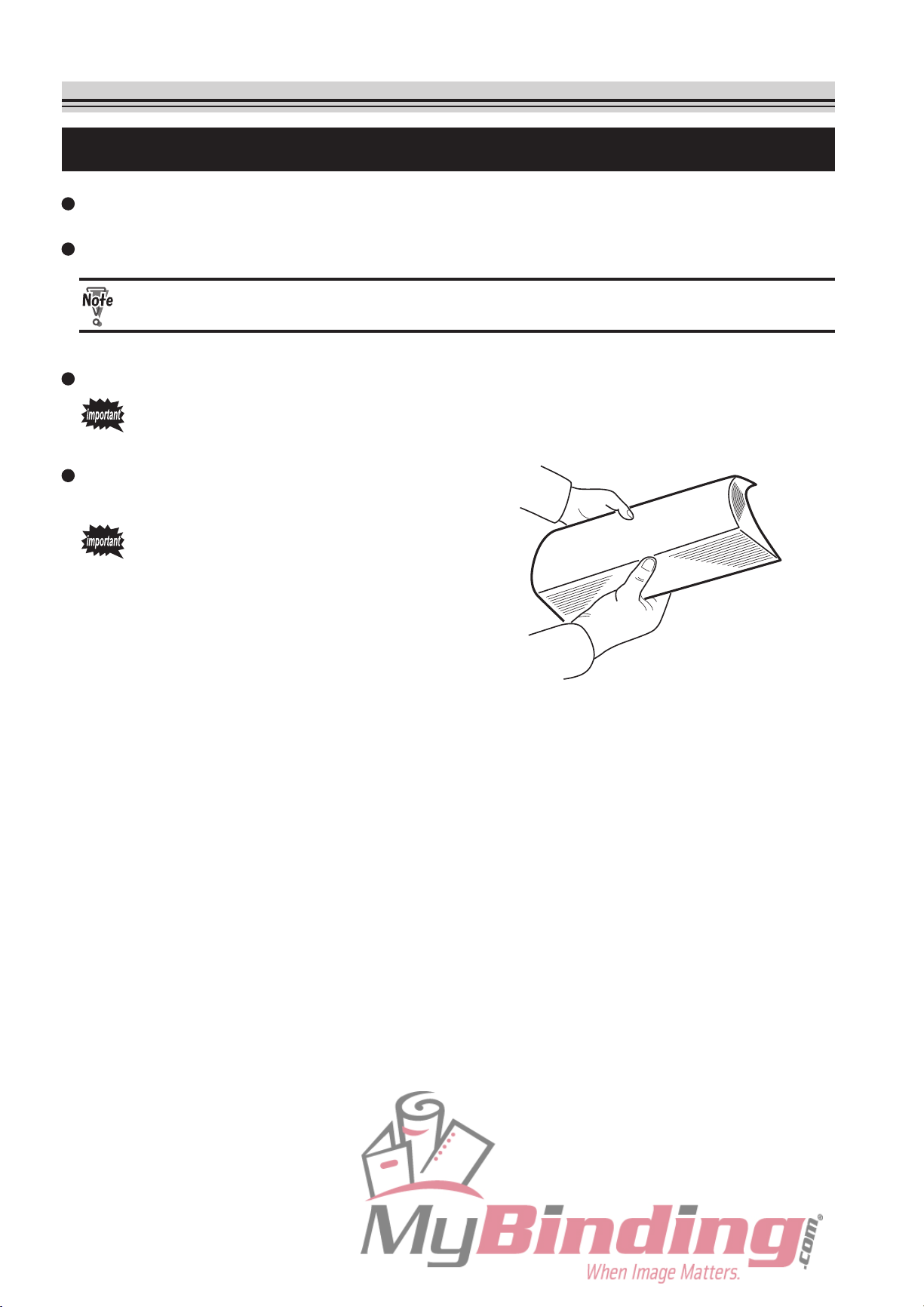
Fan paper just copied or printed well prior
to use.
Paper just copied or printed contains
considerable static electricity, and
if not fanned well, problems such as
double-feed will result.
1-8
Page 18
4-2. Precautions on Stacking Paper
4. HANDLING OF PAPER
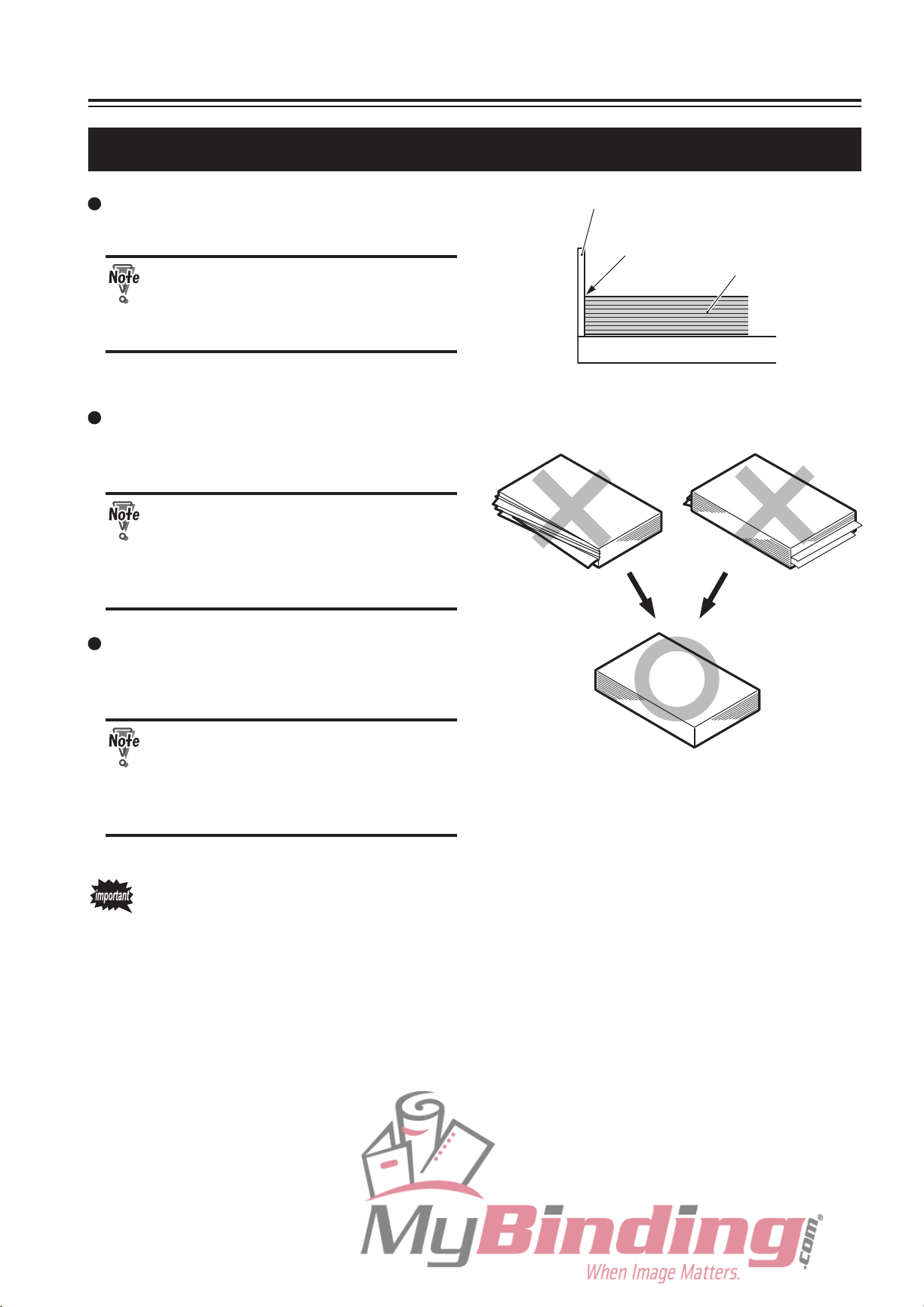
Stack the paper so that the lead edge
touches the shutter gently.
I f th e r e is a ga p b e t w e en th e
lead edge and shutter, the paper
detection sensor will not function
properly.
Do not stack paper on the paper feed tray
with the left and right sides of the paper
unaligned or some sheets protruding out.
If the paper is protruding on the
left or right side, the paper size
detection sensor will not function
normally and detect the paper size
accurately.
Shutter
Stack so that
there is no gap.
Paper feed tray
<Paper protruding on
the left and right sides>
Paper
<Paper protruding at
the lead and trail edges>
Do not stack paper on the paper feed tray
with the lead and trail edges unaligned or
some sheets protruding out.
If the paper is protruding at the lead
or trail edge, paper will not be fed
stably, resulting in problems such
as paper feed e rror and folding
misalignment.
In some cases, paper may not be fed smoothly into the folding plate due to the
environment (temperature, humidity), paper thickness, paper type, paper states, and
processing speed, etc., and as a result, the paper may not be folded properly.
In such cases, lower the processing speed, or improve the paper states before use.
<Paper properly aligned>
1-9
Page 19

Memo
1-10
Page 20

Chapter 2
BASIC OPERATION
2-1
Page 21
3
2
1
3
2
1
3
2
1
3
2
1
3
2
1
1. STANDARD FOLDING OF STANDARD PAPER
1-1. Standard Paper
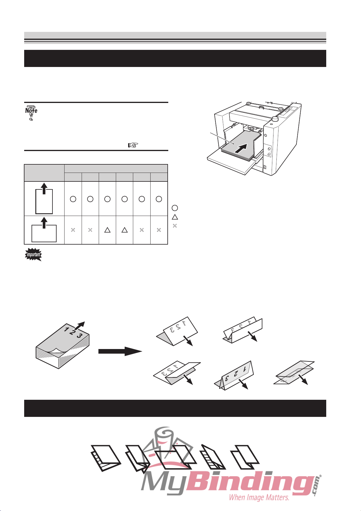
There are six types of standard paper sizes; A3, B4, A4, B5, A5, and B6. All these sizes are
detected as standard paper only when stacked in the short edge feeding direction (direction
shown in the figure).
For A4 and B5 sizes, these can be
used as non-sta ndard paper e ven
when stacked in the long edge feeding
direction. (Refer to Chapter 3 APPLIED
E “ 1 . STANDARD FOLDING OF
US
NON-STANDARD PAPER” (
Table of paper stacking direction
Stacking
direction
A3 B4
Paper size
A4
B5 A5 B6
p.3-2).)
Paper
: Can be used as standard paper
: Can be used as non-standard paper
: Cannot be used
×
× × ×
When stacking paper on the paper feed tray, take note of the front/back, top/end of the
paper.
cause the relations between the folding misalignment state and the front/back, top/
Be
end of the paper must also be taken into consideration when checking the finish by test
folding.
<Example> When paper
shown and finished in the following standard folding modes
Paper feed direction
Paper stacked on
paper feed tray
(front is gray and back is white) is stacked on the paper feed tray as
<Irregular accordion fold> <Letter fold> <Accordion fold>
<Single fold> <Double fold>
Ejection
direction
1-2. Standard Folding Modes
There are five types of standard folding modes; single fold, double fold, irregular accordion
fold, letter fold, and accordion fold.
Letter
fold
Accordion
fold
2-2
Single
fold
Double
fold
Irregular
accordion fold
Page 22
ON
OFF
1. STANDARD FOLDING OF STANDARD PAPER
MAX
1-3. Operation Procedure
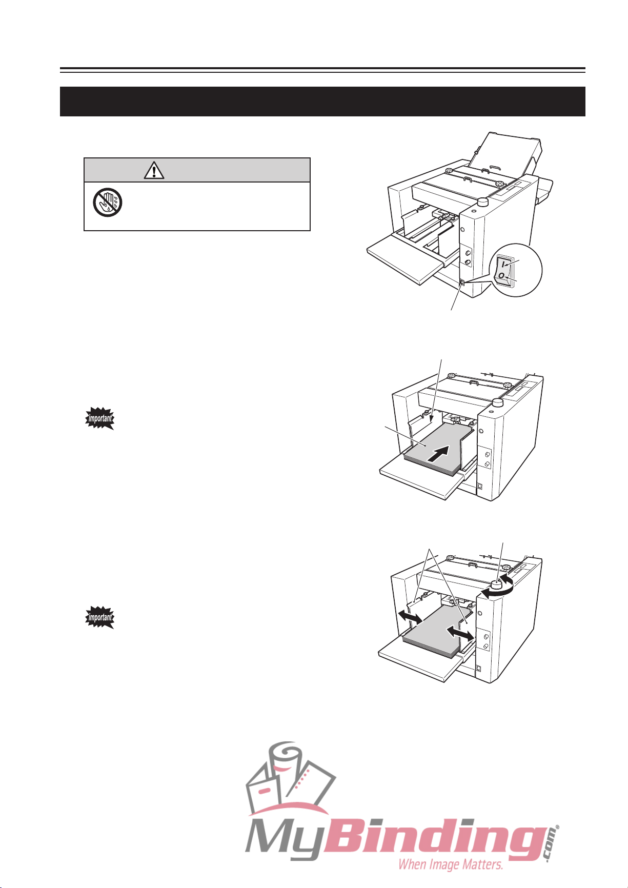
Turn on the power switch.
1
WARNING
Do not touch the power switch
with wet hands.
Otherwise electric hazards may occur.
Power switch
Stack paper on the paper feed tray.
2
Push in the paper until the lead edge touches
the shutter below the paper feed inlet slightly.
Do not overstack paper. Paper can
be stacked up to the mark “MAX”
on the side guide (about 100 mm
high).
Move the side guides according to
3
the paper width.
Move the side guides to the left and right by
rotating the side guide dial.
Be sure to adjust the side guides
accor ding to the paper width,
otherwise the unit may not operate
normally or problems such as
folding misalignment may result.
Maximum stacking height
Paper
Side guides
Side guide dial
2-3
Page 23
1. STANDARD FOLDING OF STANDARD PAPER
Standard folding lamp
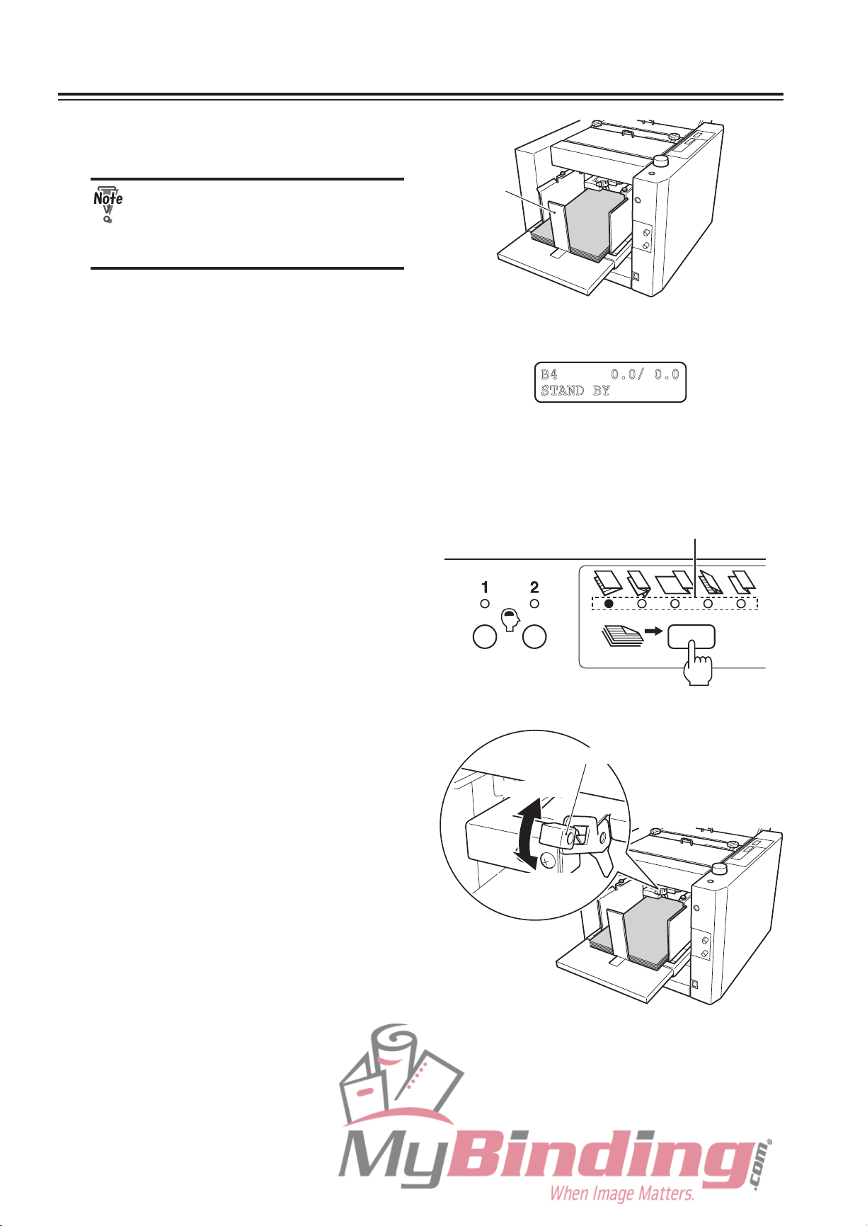
Set the rear guide at the trail edge of
4
the paper.
Be sure to set the rear guide.
Starting the unit without setting
it will cause the separating air to
blow away the paper.
Check the paper size displayed at the
5
top left of the LCD.
If the side guides are not set at the designated
position, the paper size will not be displayed
even when using standard size paper. Make
sure t he side gui des are set to the cor rec t
position.
Press the folding mode key to select
6
the desired fold.
Each time the folding mode key is pressed, the
standard folding lamp will light up in order from
left to right, starting from single fold.
Rear guide
<LCD message in standard paper/standard folding>
. /
T
Adjust the level sensor height using
7
the level sensor adjusting lever.
The stan dard heig ht of the leve l sen sor is
between “1” and “2”.
Moving the adjusting lever to “1” raise s the
paper feed position and moving it to “2” lowers it.
If mis-feed occurs with thick paper, adjust to “1”.
If double-feed occurs with thin paper, adjust to
“2”.
Level sensor adjusting lever
To “2” side
To “1” side
2-4
Page 24
1. STANDARD FOLDING OF STANDARD PAPER
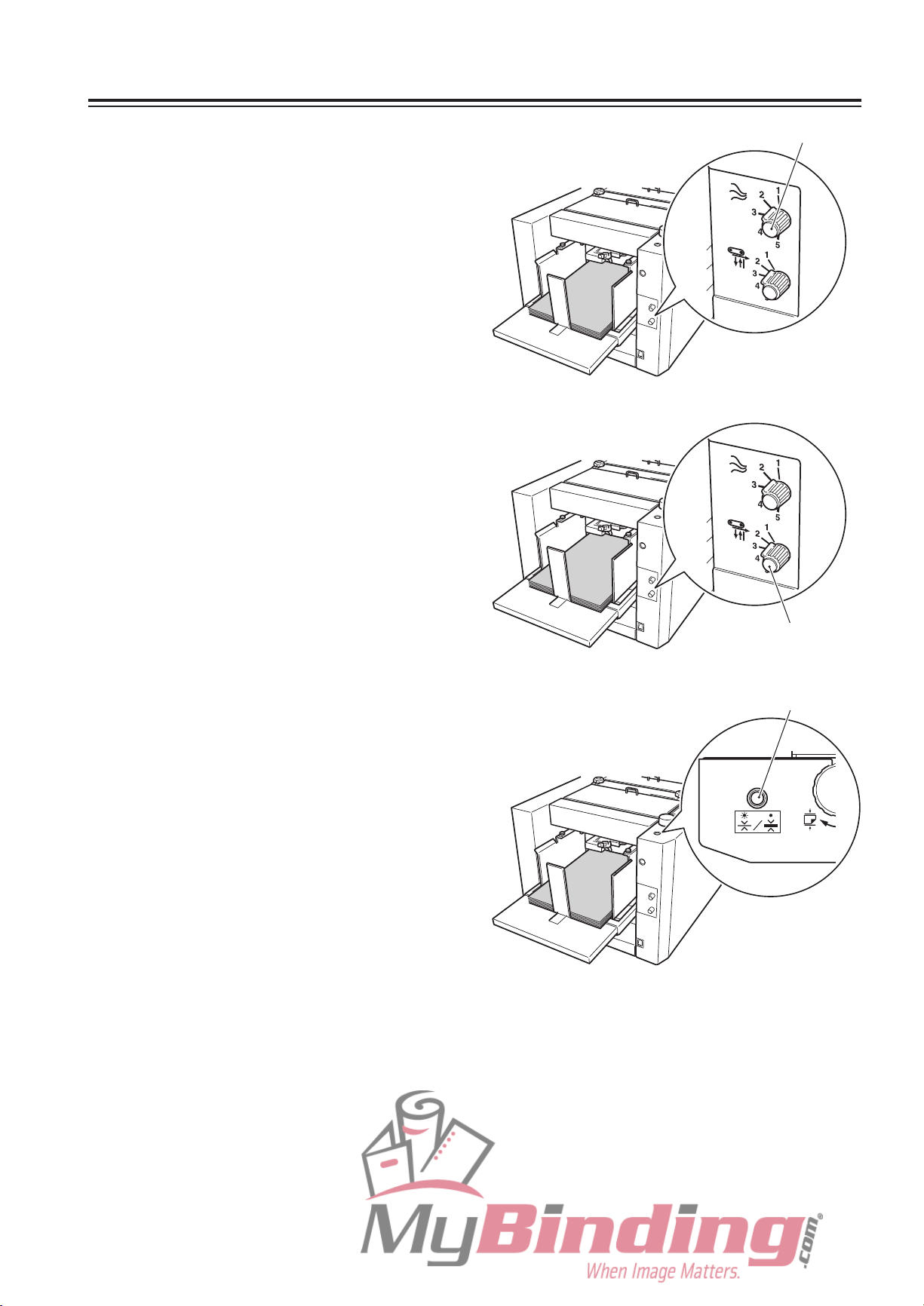
Adjust the separating air amount
8
using the separating air adjusting
knob.
The standard amount of the separating air is “2”.
The larger the figure, the stronger the separating
air blown will be. When using large art paper or
coated paper, adjust the knob to a large value.
Adjust to a small value for small and thin paper.
Adjust the separator height using the
9
separator adjusting knob.
The standard height of the separator is one
where the separator is touching the suction belt
lightly. Normally, set the knob to “2”.
If mis-feed occurs, adjust the knob to a large
value. If double-feed occurs, adjust to a small
value.
Separating air adjusting knob
Set the thin paper feed button to
10
ON or OFF according to the paper
thickness.
Press the button to select ON or OFF. When the
lamp is lit, the thin paper function is ON. When
the lamp is off, the thin paper function is OFF.
Set to ON if the paper thickness is less than 81.4
g/m2.
Separator adjusting knob
Thin paper feed button
2-5
Page 25
1. STANDARD FOLDING OF STANDARD PAPER
Speed 1 Speed 5
Speed 1 lamp blinks
(When set slower than
speed 1)
Speed 5 lamp blinks
(When set faster than
speed 5)
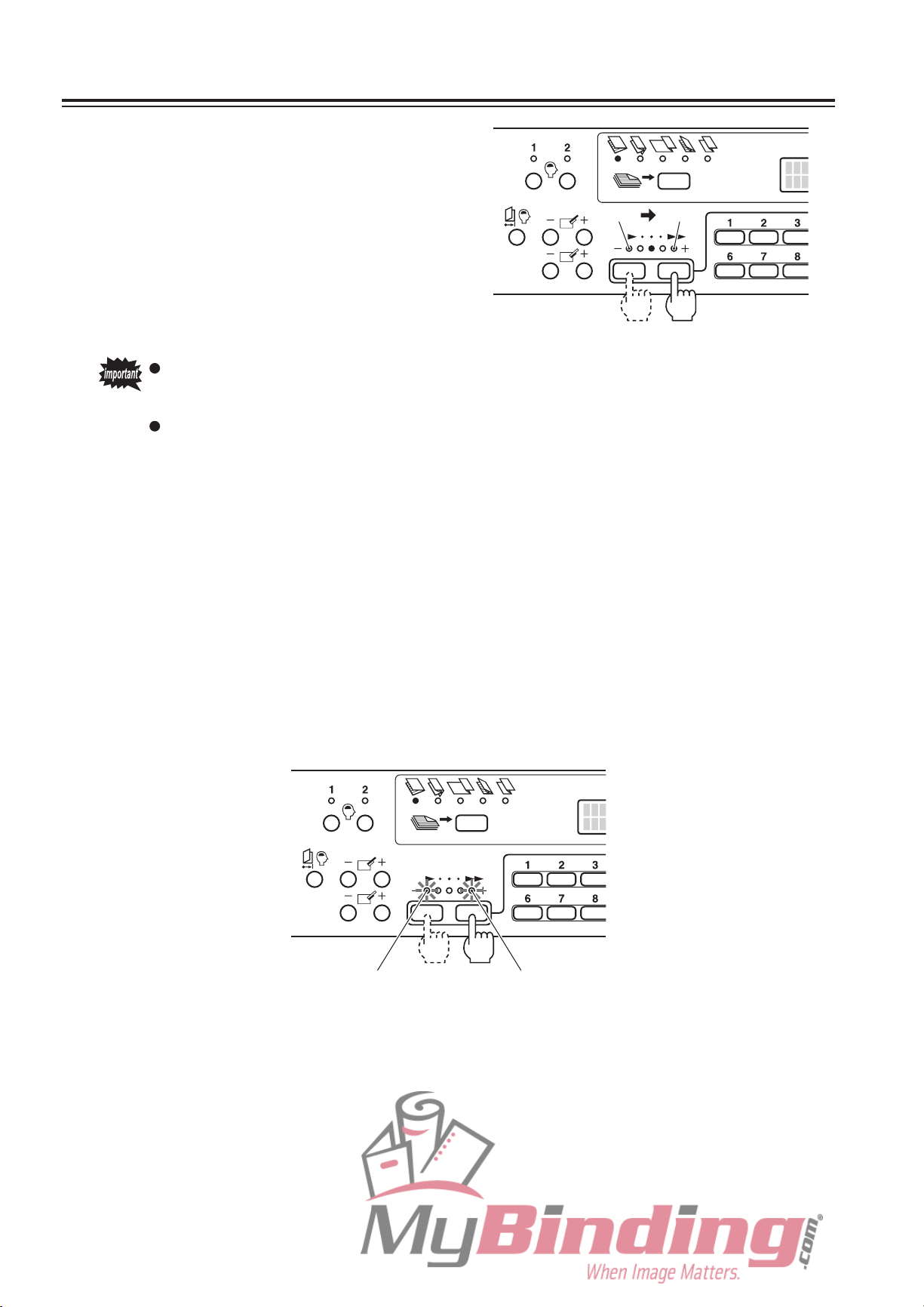
P re ss th e s p ee d k ey to s et th e
11
processing speed.
Five speed can be selected (Speed 1 to 5).
Every time the “+” key is pressed, the speed
lamp lights up towards the right and the speed
increases. Every time the “–” key is pressed, the
speed lamp lights up towards the left and the
speed decreases.
When the power is turned on, the speed used
the last time is displayed.
When using thin and flimsy paper, setting the speed to 5 may cause problems
such as paper jam and deformed folding. Set to lower speeds.
The speed can be set faster than 5 or slower than 1. (This setting becomes invalid
when the power is turned OFF, and when the power is turned ON again, it will be
set to speed 5 or 1.)
<To set faster than speed 5>
1) Press the “+” key until the speed 5 lamp lights up.
2) Press and hold the “+” key for more than three seconds. The lamp will stop lighting and start
blinking.
To return to speed 5, press the “–” key once. The lamp will start lighting.
<To set slower than speed 1>
1) Press the “–” key until the speed 1 lamp lights up.
2) Press and hold the “–” key for more than three seconds. The lamp will stop lighting and start
blinking.
To return to speed 1, press the “+” key once. The lamp will start lighting.
2-6
Page 26
1. STANDARD FOLDING OF STANDARD PAPER
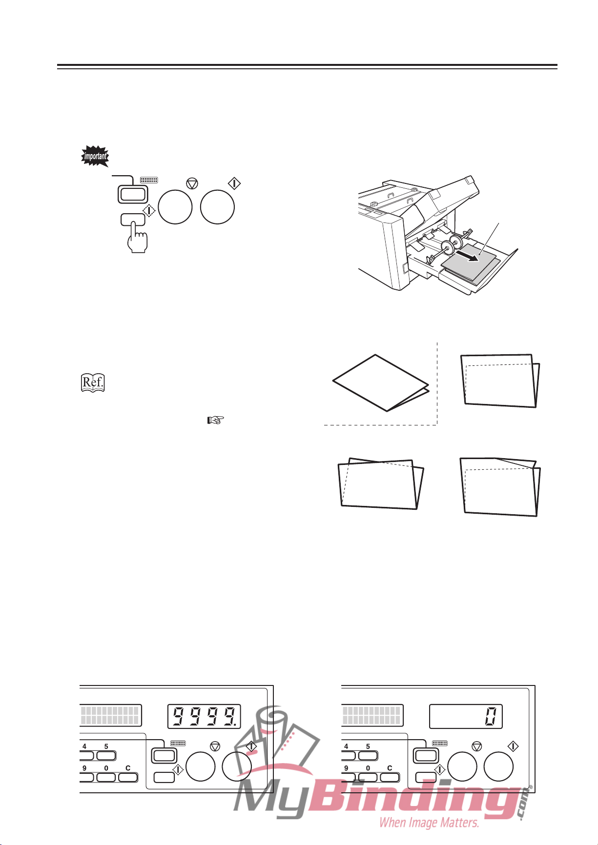
Press the test key to perform test folding.
12
Test folding feeds two sheets of paper and allows the finish to be checked.
When the test key is pressed, the LCD displays “WAIT” and the folding stopper starts moving to the set
position. When it completes moving, the message changes to “TEST RUN” and test folding starts.
Test folded paper are not counted in the number of sheets processed.
Folded paper
Check the finish of test folding.
13
Check for folding misalignment using the second
test folded sample.
If folding misalignments occur, refer
to Chapter 4 TROUBLESHOOTING
“ 1 . C O R RE C T IN G F O LD I NG
MISALIGNMENT” (
Select the method of using the counter.
14
The counter can be used in two ways: subtract count and add count.
Enter the number of sheets to be processed using the numerical keys first before beginning operations.
In this case, the counter will be set to the subtract count method. (A period is displayed at the bottom right
where the count is displayed.)
If the clear key is pressed to clear the counter to “0” before beginning operations, the counter will be set to
the add count method.
Up to four digits (9999) can be displayed.
p.4-2).
<Normal folding>
<Folding misalignment
along sides of paper>
<Folding misalignment along
vertical length of paper>
<Deformed folding>
<Counter display for “Subtract count method”> <Counter display for “Add count method”>
2-7
Page 27

1. STANDARD FOLDING OF STANDARD PAPER
The following description is based on the subtract count method.
Press the numerical keys to enter the
15
number of sheets to be processed.
Press the start key to start folding.
16
To cancel operations halfway through, press the
stop key. Pressing the start key another time
resumes operations.
When the number entered is reached in folding
operations, the buzzer sounds “pi...pi...”, and
paper feed will stop automatically.
If the paper feed tray runs out of paper, the
buzzer sounds “pi.pi.pi”, and the unit will stop
automatically.
After stopping, the paper feed tray moves down
automatically.
If double-feed, continuous-feed, or mis-feed occurs during folding operations, refer to the
following table and re-adjust the adjusting knobs and adjusting lever.
Adjusting knobs and
lever used
Separating air adjusting
knob
Level sensor adjusting
lever
Separator adjusting
knob
Double-feed/Continuous-feed Mis-feed
<When using thin paper>
Adjust
weaken the separating air.
<When using thick paper>
A
increase the separating air amount.
Move
sensor.
Adjust
raise the separator.
the knob to a smaller value and
djust the knob to a larger value and
the lever to “2” and lower the level
the knob to a smaller value and
Error state and adjustment method
Adjust the knob to a larger value and
increase the separating air amount.
Move the lever to “1” and raise the level
sensor.
Adjust the knob to a larger value and
lower the separator.
2-8
Page 28

Chapter 3
APPLIED USE
3-1
Page 29

1. STANDARD FOLDING OF NON-STANDARD PAPER
Paper that is not A3, B4, A4, B5, A5, or B6 are considered non-standard paper. Standard
paper that is fed in the long edge feeding direction is also considered as non-standard paper.
When using non-standard paper, the length must be entered and registered before beginning
folding operation.
Starting operations without registering the paper length will display the error message
“INPUT LENGTH” on the LCD.
1-1. Paper Size Restrictions
Paper sizes which can be used are the sizes
within the range shown on the right.
To insu r e t h e quality of the fo l d
when paper width is 120 mm, it is
recommend not to exceed 240 mm in
length.
Width: 120 to 297 mm
1-2. Operation Procedure
Measure the length of the paper to be used.
1
The length is the side parallel to the paper feed direction (see top figure).
Turn on the power switch.
2
Paper feed direction
Paper
Length: 182 to 432 mm
Stack paper on the paper feed tray.
3
Move the side guides according to the paper width.
4
Set the rear guide at the trail edge of the paper.
5
For details of steps 2 to 5, refer to “1-3. Operation Procedure” in Chapter 2 BASIC
OPERATION “1. STANDARD FOLDING OF STANDARD PAPER” (
3-2
p.2-3).
Page 30

1. STANDARD FOLDING OF NON-STANDARD PAPER
�
Pr es s t h e m od e k ey to d is pl ay
6
“LENGTH” on the LCD.
Using the numerical keys, enter the
7
length of the paper.
The paper length which can be entered ranges
from 182 to 432 mm.
If the value enter ed exc eeds t he all owable
range, the buzzer sounds and the LCD shows
“TOO LONG” or “TOO SHORT”.
If a paper length has already been
registered, press the clear key to
clear this value before entering the
length with the numerical keys.
Press the stop key.
8
The entered paper length is registered, and the
value is displayed at the top left of the LCD.
The paper length data registered is
erased when the power is turned
off. To save the registered data,
set the last time fold mode at the
function setting mode screen.
R
efer to “4-2. Operation Mode
(
Setting” (
p.3-12).)
<Canceling non-standard paper length setting>
1) Press the mode key to display “LENGTH” on
the LCD.
2) Press the clear key to display “OFF”.
3) Press the stop key.
The unit returns to the automatic paper size
detection mode.
3-3
Page 31

1. STANDARD FOLDING OF NON-STANDARD PAPER
Press the folding mode key to select the desired fold.
9
Adjust the level sensor height.
10
Adjust the separating air amount.
11
Adjust the separator height.
12
Set the thin paper feed button to ON or OFF according to the paper thickness.
13
Press the speed key to set the processing speed.
14
Press the test key to perform test folding.
15
Check the finish of test folding.
16
Press the numerical keys to enter the number of sheets to be processed.
17
(Skip this step if using the add-count counter.)
Press the start key to start folding.
18
For details of steps 9 to 18, refer to “1-3. Operation Procedure” in Chapter 2 BASIC
OPERATION “1. STANDARD FOLDING OF STANDARD PAPER” (
p.2-4).
3-4
Page 32

2. CUSTOM FOLDING
Custom folding is the method of folding paper by specifying and registering the positions (folding
positions) of the folding stoppers of folding plates 1 and 2.
2-1. Paper Size Restrictions
Paper sizes which can be used are the sizes
within the range shown on the right.
To insu r e t h e quality of the fo l d
when paper width is 120 mm, it is
recommend not to exceed 240 mm in
length.
However, the length of the folded plane (see
right figure) which can be folded by folding
plates 1 and 2 is restricted.
Do not set the folded paper length to above
250 mm.
Folding plate 1 : 42 to 325 mm
Folding plate 2 : 0 mm*/47 to 217 mm
As folding plate 2 is not used in single folding, it is 0
∗
mm.
Paper feed direction
Paper
Width: 120 to 297 mm
Length: 182 to 432 mm
Length of
folded plane
2-2. Operation Procedure
The following describes the custom folding procedure taking accordion fold as an example.
C r e a t e th e f o l d i n g sa m p l e o f
1
accordion fold with the paper to be
used.
Measure the size of each folded plane
2
(A and B) of the sample, and the
folded paper length C.
Turn on the power switch.
3
Stack paper on the paper feed tray.
4
Move the side guides according to the paper width.
5
A (200 mm)
B (95 mm)
Paper feed
direction
C (105 mm)
Ejection
direction
3-5
Page 33
2. CUSTOM FOLDING
Set the rear guide at the trail edge of the paper.
6
For details of steps 3 to 6, refer to “1-3. Operation Procedure” in Chapter 2 BASIC
OPERATION “1. STANDARD FOLDING OF STANDARD PAPER” (
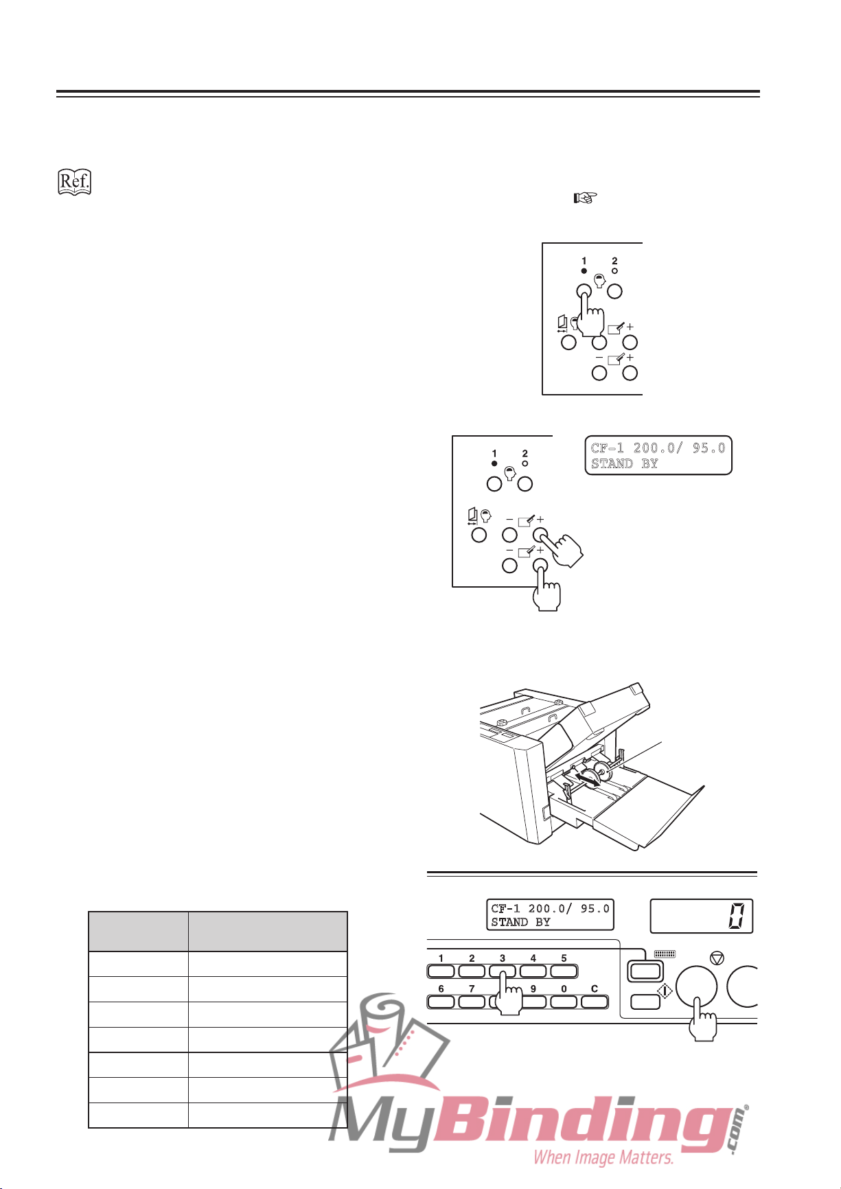
Press the custom folding registration
7
key 1 or 2 until the buzzer sounds
“pi.pi...” to switch to the custom
folding mode.
p.2-3).
Set the folding stopper positions.
8
Press the “+” key of the folding plate 1 folding
stopper a djusting key and move the folding
stopper to the measured dimensions A (200
mm) of the sample.
Press the “+” key of the folding plate 2 folding
stopper a djusting key and move the folding
stopper to the measured dimensions B (95 mm)
of the sample.
The position moved to by the folding stopper is
displayed in mm on the LCD.
Set the position of the stacker roller.
9
The position of the stacker roller needs to be
changed according to the folded paper length.
Selecting and pressing a numerical key (1 to 7)
while pressing the stop key moves the stacker
roller to the position set. Refer to the following
table for approximate set positions.
In this example, the folded paper length C is 105
mm. Therefore press the numerical key 3 while
pressing the stop key.
. /
T
Stacker roller
Approximate stacker roller set position
Numerical
key setting
1
2 To 80
3 81 to 110
4 111 to 140
5 141 to 170
6 171 to 210
7 211 to 250
Folded paper
length (mm)
∗
3-6
∗
Use numerical key “1” if paper jams at the “2” position.
Page 34

2. CUSTOM FOLDING
Adjust the level sensor height.
10
Adjust the separating air amount.
11
Adjust the separator height.
12
Set the thin paper feed button to ON or OFF according to the paper thickness.
13
Press the speed key to set the processing speed.
14
Press the test key to perform test folding.
15
Check the finish of test folding.
16
For details of steps 10 to 16, refer to “1-3. Operation Procedure” in Chapter 2 BASIC
OPERATION “1. STANDARD FOLDING OF STANDARD PAPER” (
After completing all settings, register
17
the custom folding setting.
Press the custom folding registration key 1 or 2
until the buzzer sounds “pi.pi...”.
The registered data is preserved
even after the power is turned off.
<Changing/erasing custom folding registration data>
1) Press the folding mode key so that the registration lamp (1 or 2) of the custom folding mode registering
the data to be changed or erased lights up.
2) To change the registered data, perform steps 8 to 17 of the above registration procedure. The data will
be rewritten.
To erase the data, proceed to step 3).
3) Press the custom folding registration key (1 or 2) registering the data to be erased until the buzzer
sounds “pi.pi...” (press for about two seconds), and then continue pressing for another two seconds until
the buzzer sounds “pi...”. (Total four seconds)
When the registered data is erased, the single folding lamp will light up.
p.2-4).
Press the numerical keys to enter the number of sheets to be processed.
18
(Skip this step if using the add-count counter.)
Press the start key to start folding.
19
For details of steps 18 and 19, refer to “1-3. Operation Procedure” in Chapter 2 BASIC
OPERATION “1. STANDARD FOLDING OF STANDARD PAPER” (
p.2-8).
3-7
Page 35

3. USING SPECIAL PAPER
3-1. Art Paper, Coated Paper
Fan the paper well before stacking.
Set the separating air adjusting knob to a
larger value.
Set the separato r adjusting knob to a
smaller value.
If the paper is folded abnormally, lower the
processing speed.
If paper feed error occurs and it cannot be
correct by the above two adjusting knobs
and level sensor adjusting lever, lower the
processing speed.
Separating air adjusting knob
Separator adjusting knob
3-8
Page 36

3-2. Recycled Paper
Speed 1 lamp blinks
(When set slower than speed 1)
Fan the paper well before stacking.
3. USING SPECIAL PAPER
Set the separating air adjusting knob to a
smaller value.
Set the separato r adjusting knob to a
larger value.
Set the processing speed to a low speed.
If paper feed error occurs frequently,
set the processing speed slower
than speed 1. Press and hold the
“–” speed key for more than three
seconds with the speed 1 lamp lit.
This lamp will start blinking.
Separating air adjusting knob
Separator adjusting knob
3-9
Page 37

3. USING SPECIAL PAPER
3-3. B6 Size Paper
Paper may jam more easily at the stacker roller according to the paper thickness, type, and
folding mode. Perform the following procedure if paper jams frequently.
Loosen the two knob screws and
1
remove the paper ejection guide.
Change the stacker roller height.
2
Chapter 4 TROUBLESHOOTING
“2-2. Changing the Stacker Roller
Height” (
p.4-14)
Lever
Stacker belt
Paper ejection guide
Stacker roller
Set the operations of the stacker belt
3
to “CONTINUOUS” at the function
setting mode screen.
“ 4 - 7 . S t ac k e r B e l t S e t t i n g ”
p.3-20)
(
After completing folding operations, be sure to return the places changed in steps
4
1 to 3 to their original state.
Depending on the paper thickness, type, and folding mode, the ejected paper may not be
aligned and stacked neatly on the paper receiving tray.
If paper alignment is poor, hook the auxiliary paper ejection guide to the stacker roller shaft.
<Example of paper stacked neatly>
< T CK L
CO
Auxiliary paper ejection guide
To remove the paper ejected with the auxiliary paper ejection guide mounted, lift the
guide edge or remove the guide first.
3-10
Page 38
4. FUNCTION SETTING MODE
The function setting mode is a function for shortening the operation procedure or adjusting
according to the paper used based on the purpose of the user.
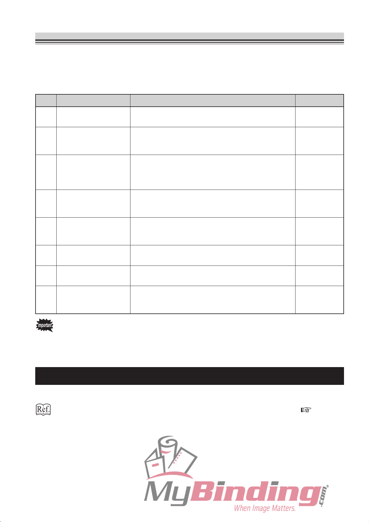
The function setting mode consists of the following eight types.
No. Mode Purpose Default setting
1 Non-standard paper
length setting
2 Operation mode setting S
3 Interval setting S
4 Separating air strength
setting
5 Paper feed interval
setting
6 Stacking amount setting The
7 Stacker belt setting Select
Set
and register the paper length when standard folding
non-standard paper.
etting for shortening the operation procedure. Select
from three modes “NORMAL”, “LAST TIME FOLD”, and
“STOPPER FIXED”.
etting this setting to ON repeatedly pauses operations
for ever y specifi ed n umber of shee ts a nd re star ts
operations after several seconds. The pause time can be
selected from “3 SEC”, “5 SEC”, and “10 SEC”.
T
he separ a t ing air volume c a n be s e lected f r o m
“NORMAL” a nd “L I G H T ” a c c o r d i n g t o t h e paper
thickness.
T
he processing speed for single fold, double fold, and
letter fold of standard paper can be selected from “FAST”,
“NORMAL”, and “SLOW”.
volume of paper stacked on the paper feed tray can
be selected from “HIGH”, “NORMAL”, “LOW”.
“NORMAL” and “CONTINUOUS”.
the operations of the stacker belt from two modes
OFF
NORMAL
OFF
NORMAL
NORMAL
HIGH
NORMAL
8 Thick paper stopper
correction setting
T
he correction value of the folding stopper positions of
the folding plates can be changed for thick paper. Select
“NOT CORRECTED” or “CORRECTED”.
The No. 1 registered data of paper length will be preserved even after the power is turned
off when the No. 2 operation mode setting is set to last time fold mode.
The No. 2, 4 to 8 settings will be preserved even after the power is turned off.
The No. 3 setting will be erased when the power is turned off.
4-1. Non-standard Paper Length Setting
Set and register paper length in this mode when using non-standard paper.
For details, refer to “1. STANDARD FOLDING OF NON-STANDARD PAPER” ( p.3-2).
NOT
CORRECTED
3-11
Page 39

4. FUNCTION SETTING MODE
4-2. Operation Mode Setting
Setting to the last time fold mode or folding stopper fixed mode enables setting operations
after power ON to be omitted, thus shortening the time to the start of work. At shipment, this is
set to the normal mode.
(1) Last time fold mode
Function which starts the unit at the settings used the last time when the power is turned ON.
When set to this mode, the following will be set automatically at power ON.
To correct the folding stopper position and save the data, be sure to register the
corrected data. Otherwise, the corrected data will be erased when the power is turned
OFF.
Setting Last time fold mode Normal mode
Paper size
Folding mode S
Stacker roller position S
Processing speed Set
Sta ndard pap er is auto mati cal ly
detected.
When non-standard paper length is
registered, the registered data is set.
et t o the f oldi ng mod e when the
power was turned OFF.
et to the position when the power
was turned OFF.
to the speed when the power was
turned OFF.
Standa rd p ape r is auto mat ica lly
detected.
When using non-standard paper, the
paper length must be registered.
Single folding
Default setting
Set to the speed when the power was
turned OFF.
(2) Folding stopper fixed mode
Mode for omitting settings of the control panel when folding paper under the same conditions
at all times. When set to this mode, the folding stopper position, stacker roller position, and
processing speed will be fixed. Therefore initial settings of the unit will be omitted when the
power is turned ON, enabling folding to be started immediately.
3-12
When set to this mode, the folding mode, processing speed, stacker roller position
cannot be selected. Before setting this mode, perform test folding in the “normal
mode” and fix the folding stopper position, processing speed, and stacker roller
position.
To correct the folding stopper position and save the data, be sure to register the
corrected data. Otherwise, the corrected data will be erased when the power is turned
OFF.
When set to this mode, the standard folding lamp and custom folding registration lamp
will not be lit.
Page 40

4. FUNCTION SETTING MODE
The following shows the recommended operation modes by purpose. Change the operation
mode according to purpose.
<Example of purpose> <Recommended operation mode>
When the paper size and folding mode differs
each time
When various people use the machine
When the paper size and folding mode are
always more or less the same, but want to
change it occasionally
When the paper size and folding mode are the
same every time, and want to start operations
immediately after power ON
Normal mode (Default setting)
Last time fold mode
Folding stopper fixed mode
The following shows how to set the last time fold mode and folding stopper fixed mode.
Pr ess th e mo de k ey an d se le c t
1
“MODE”.
Press the speed key and select “LAST
2
TIME FOLD” or “STOPPER FIXED”.
<When last time fold <When folding stopper
mode> fixed mode>
<
IX
Press the stop key and register the
3
setting.
Wh en se t to the last time fold mode, “REF”
appears at the bottom of the LCD.
When set to the folding stopper fixed mode, “FIX”
appears at the top of the LCD.
<When last time fold <When folding stopper
mode> fixed mode>
/ .
/
3-13
Page 41

4. FUNCTION SETTING MODE
<Returning to the normal mode>
1) Press the mode key and select “MODE”, and then
select “NORMAL” using the speed key.
2) Pressing the stop key switches to the normal
mode, and “REF” or “FIX” on the LCD disappears.
3-14
Page 42

4. FUNCTION SETTING MODE
4-3. Interval Setting
When this setting is set to ON, the unit will automatically repeat pause and restart at the
specified number of sheets as shown in the figure below. At shipment, this is set to “OFF”.
<Example> To remove ejected paper from the paper receiving tray or changing the direction
of the paper placed during pause
Start
Pause (Select the pause time from 3 seconds, 5 seconds, and 10 seconds.)
Restart
Stops when paper runs out or the subtract-count counter becomes “0”.
Press the mode key and select “SET
1
INTERVAL”.
Press the speed key and select the
2
pause time from “3 SEC”, “5 SEC”, or
“10 SEC”.
Enter the number of sheets to be
3
processed until the unit pauses using
the numerical keys.
< N
/ T
The number of sheets is shown on the LCD.
The number of sheets which can be entered
ranges from 1 to 999.
T V L
/
3-15
Page 43

4. FUNCTION SETTING MODE
Press the stop key and register the
4
setting.
“I” is displayed at the bottom of the LCD.
The setting is erased when the
power is turned OFF.
<Returning setting to “OFF”>
1) Press the mode key and select “SET INTERVAL”,
and then select “OFF” using the speed key.
2) Pressing the stop key clears the setting and “I” on
the LCD disappears.
/
N I
V
3-16
Page 44

4. FUNCTION SETTING MODE
4-4. Separating Air Strength Setting
Function for adjusting the air amount for separating paper. At shipment, this is set to
“NORMAL”.
<Example> To weaken the air as paper feed error occurs frequently when thin paper or small
paper is used
Press the mode key and select “AIR
1
POWER”.
Pres s the sp eed ke y and se lec t
2
“LIGHT”.
Press the stop key and register the
3
setting.
<Returning setting to “NORMAL”>
1) Press the mode key and select “AIR POWER”,
and then select “NORMAL” using the speed key.
R >
I T
>
2) Press the sto p ke y and switch the set tin g to
“NORMAL”.
3-17
Page 45

4. FUNCTION SETTING MODE
4-5. Paper Feed Interval Setting
Function for changing the processing speed when single folding, double folding, or letter
folding standard paper. At shipment, this is set to “NORMAL”.
<Example>
Press the mode key and select “FEED
1
SPEED”.
Pres s the sp eed ke y and se lec t
2
“FAST” or “SLOW”.
To raise the processing speed when the paper used and folding mode are
restricted to the above three types (This setting is valid only when the speed
5 lamp is blinking. Refer to “1-3. Operation Procedure” in Chapter 2
BASIC OPERATION “1. STANDARD FOLDING OF STANDARD PAPER”
p.2-6).)
(
To lower the processing speed to prevent paper jamming and paper feed
errors
Th e “ FA S T ” s e t t i n g i s v a l id
only when the speed 5 lamp is
blinking. (Refer to “1-3. Operation
Procedure” in Chapter 2 BASIC
O P E RA T IO N “1 . ST A N D A R D
FOLDING OF STANDARD PAPER”
p.2-6).)
(
T
Press the stop key and register the
3
setting.
<Returning setting to “NORMAL”>
1) Press the mode key and select “FEED SPEED”,
and then select “NORMAL” using the speed key.
2) Press the sto p ke y and switch the set tin g to
“NORMAL”.
3-18
< >
Page 46

4. FUNCTION SETTING MODE
4-6. Stacking Amount Setting
Function which changes the amount of paper stacked on the paper feed tray in three levels.
The distance descended by the paper feed tray when paper runs out changes according to
the setting. At shipment, this is set to “HIGH”.
The number of sheets stacked for each setting is as follows for fine quality paper 81.4 g/m2 or
equivalent.
“HIGH” : 1000 sheets
“NORMAL” : 600 sheets
“LOW” : 300 sheets
<Example> To decrease the amount stacked when the number of sheets used for one folding
operation is little and folding is to be carried out while changing the paper type
Pr ess th e mo de k ey an d se le c t
1
“QUANTITY”.
Pres s the sp eed ke y and se lec t
2
“NORMAL” or “LOW”.
Press the stop key and register the
3
setting.
<Returning setting to “HIGH”>
1) Press the mode key and select “QUANTITY”, and
then select “HIGH” using the speed key.
N >
N >
I
2) Press the stop key and switch the setting to “HIGH”.
3-19
Page 47

4. FUNCTION SETTING MODE
4-7. Stacker Belt Setting
Function for changing the operation mode of the stacker belt. At shipment, this is set to
“NORMAL”. At this time, the stacker belt operates according to the paper ejection timing.
The mode
and folding mode.
<Example> If paper is not ejected neatly or paper jams frequently at the stacker roller
When switching to “CONTINUOUS”, change the stacker roller height to the top and
remove the paper ejection guide. If the setting has been returned to “NORMAL”, return
the stacker roller and paper ejection guide to their original positions. (Refer to “3-3. B6
Size Paper” (
Pr ess th e mo de k ey an d se le c t
1
“STACKER BELT”.
can be changed so the stacker belt operates continuously, according to the paper
hen double folding B6 size paper, etc., set so that the stacker belt operates
w
continuously.
p.3-10).)
Pres s the sp eed ke y and se lec t
2
“CONTINUOUS”.
Press the stop key and register the
3
setting.
<Returning setting to “NORMAL”>
1) Press the mode key and select “STACKER BELT”,
and then select “NORMAL” using the speed key.
2) Press the sto p ke y and switch the set tin g to
“NORMAL”.
I
< >
3-20
Page 48
4. FUNCTION SETTING MODE
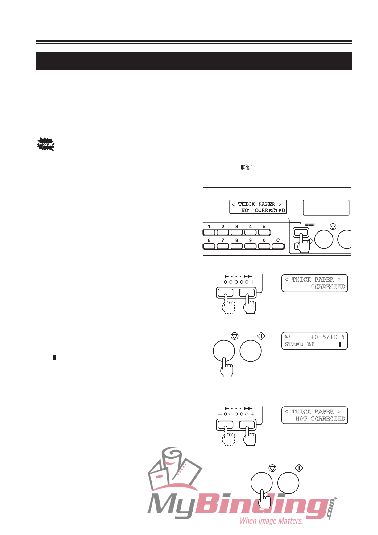
4-8. Thick Paper Stopper Correction Setting
Setting this setting to “CORRECTED” correct the folding stopper positions of both folding
plates 1 and 2 by +0.5 mm. At shipment, this is set to “NOT CORRECTED”.
<Example> When using thick paper, it is often necessary to correct the folding stopper
position to
without using the folding stopper adjusting key.
Even if set to “CORRECTED”, folding misalignment may occur due to such conditions as
using environment (temperature, humidity), paper thickness, paper type, paper state, and
processing speed. In this case, refer to Chapter 4 TROUBLESHOOTING “1-2. Correcting
Folding Misalignment Along Vertical Length of Paper” (
Press the mode key and select “THICK
1
PAPER”.
the + direction. In such cases, correction of +0.5 mm may be possible
p.4-5).
Pres s the sp eed ke y and se lec t
2
“CORRECTED”.
Press the stop key and register the
3
setting.
“ ” mark is displayed at the bottom of the LCD.
<Returning setting to “NOT CORRECTED”>
1) Press the mode key and select “THICK PAPER”,
and then select “NOT CORRECTED” using the
speed key.
/
N
2) Press the stop key and switch the setting to “NOT
CORRECTED”.
3-21
Page 49

Memo
3-22
Page 50

Chapter 4
TROUBLESHOOTING
4-1
Page 51
1. CORRECTING FOLDING MISALIGNMENT
Moving direction
of side guide
Example of
adjusting knob
needle position
Folding
misalignment A
Folding
misalignment B
Folding misalignment consists of “folding misalignment along the sides of the paper” and
“folding misalignment along the vertical length of the paper”.
Other than this, “deformed folding” may also occur due to paper characteristics, etc.
1-1. Correcting Folding Misalignment Along Sides of Paper
Before correcting, check that the skew roller spring pressure adjusting knobs are
set at the same position for the left and right sides. If their positions differ, folding
misalignment may occur. (Refer to (3) Using the skew roller spring pressure adjusting
knob (
p.4-4).)
When the folded paper is misaligned along
the sides as shown in the figure, correct the
folding misalignment using the side guide
adjusting knob and skew correction knob.
Ejection direction
(1) Adjusting the side guide adjusting knob
Loosen the side guide adjusting
1
knobs.
Mo v e th e sid e gu i d es by ha n d
2
according to the folding misalignment
direction.
Refer to the pos ition of t he adjust ing knob
needle for the adjusting amount.
Side guide adjusting knobs
Needles
Folding misalignment
at this part
4-2
Always move the left and right
side guides in the same direction.
Side guides
Page 52
1. CORRECTING FOLDING MISALIGNMENT
Rotating
direction of knob
Example of
check window
needle position
Folding
misalignment C
Folding
misalignment D
Tighten the side guide adjusting knobs and secure the side guides.
3
Perform test folding and check that the folding misalignment has improved.
4
If fol ding mis align ment is not improved
due to trimming misalignment, perform (2)
Adjusting the skew correction knob.
(2) Adjusting the skew correction knob
Loosen the skew roller fixing knobs.
1
Open the top cover L.
2
<Trimming misalignment of paper>
Skew roller fixing knobs
Top cover L
Rotate the skew correction knob
3
according to the folding misalignment
direction.
Refer to the position of the check window needle
shown in the figure for the adjusting amount.
<Adjusting amount check window>
Needle
Standard position
Skew correction knob
4-3
Page 53
1. CORRECTING FOLDING MISALIGNMENT
Close the top cover L.
4
Tighten the skew roller fixing knobs.
5
Perform test folding and check that the folding misalignment has improved.
6
After completing folding operations, be sure to return the needle back to the standard
position.
(3) Using the skew roller spring pressure adjusting knob
Open the top cover L.
1
Switch the position of the adjusting
2
k n o b a c c o r d i n g t o t h e pa p e r
thickness.
Skew roller spring
pressure adjusting knobs
Above 127.9 g/m
2
Set to the “top” position when using fine quality
paper above 127.9 g/m2 and to “bottom” position
when using paper thinner than this. However
switch while checking the folding misalignment.
Be sure to set the left and right
knobs at the same position.
Close the top cover L.
3
Less than 127.9 g/m
2
4-4
Page 54
1. CORRECTING FOLDING MISALIGNMENT
1
2
3
4
5
1
2
3
4
5
1
2 3
4
5
1
2
3
4
5
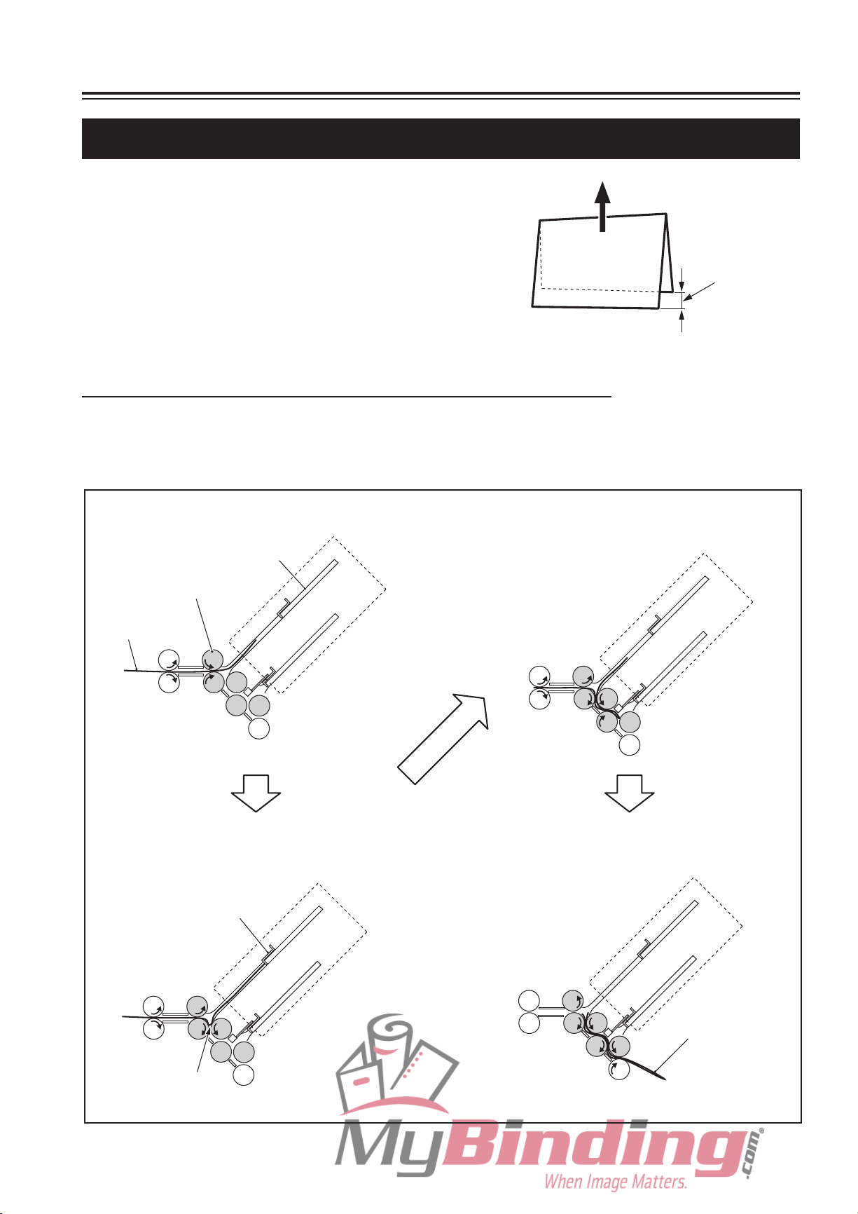
1) Paper enters folding plate 1. 3) Folding rollers 2 and 3 sandwich slackened
paper and send to folding rollers 4 and 5.
2) Paper contacts folding stopper and slacks
near folding rollers 2 and 3.
4) Single-folded paper is ejected out.
Folding plate 1
Paper
Folding rollers 1 to 5
Slacks near here.
Folding stopper
Paper
1-2. Correcting Folding Misalignment Along Vertical Length of Paper
When the folded paper is misaligned along
Ejection direction
the vertical length as shown in the figure,
adjust the positions of the folding stoppers
of fold ing plates 1 and 2 to c orrect the
misalignment.
Folding
misalignment
at this part
(1) Folding misalignment correction mechanism
This following describes single folding as an example.
The flow of paper and movements of the folding section when single folding is shown below.
In single folding, folding plate 2 is not used.
4-5
Page 55

1. CORRECTING FOLDING MISALIGNMENT
Folding plate 1 folding
stopper adjusting key
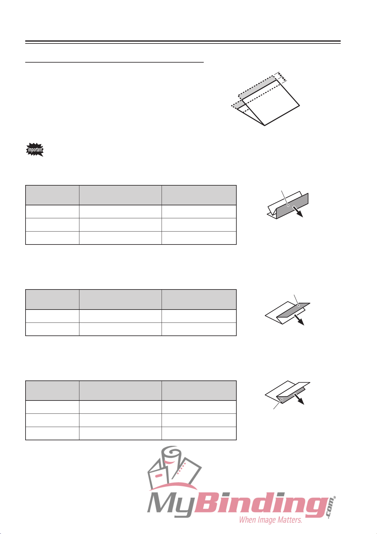
Length A of the folded plane is the length from the trail edge of the paper to the center of
paper slack.
Length B of the folded plane is the length from the center of paper slack to the folding stopper.
Therefore
by changing the position of the folding stopper, length B of the folded plane can be
adjusted.
Folded plane length B
Folded plane length A
Ejection direction
Folded plane
length A
Folded plane
length B
(2) Correcting single fold
Adjust the length of single folded plane using the “+” or “–” key of the folding plate 1 folding
stopper adjusting key.
<Example 1>
When folded
shorter than folded plane length A
plane length B is 6 mm
6 mm
In this example, by increasing the folded plane length B by 3 mm, A will become 3 mm
shorter, and as a result, folding misalignment of 6 mm in total can be improved.
To increase B, press the “+” key and move the folding stopper in the direction shown
below. To increase B by 3 mm, press the “+” key until “+3.0/ ...” appears on the LCD.
direction
+3.0 mm
+3.0 mm
–3.0 mm
+ /
4-6
Page 56

1. CORRECTING FOLDING MISALIGNMENT
Folding plate 1 folding
stopper adjusting key
<Example 2>
When folded plane length B is 3 mm
longer than folded plane length A
3 mm
In this example, by shortening the folded plane length B by 1.5 mm, A will become 1.5
mm longer, and as a result, folding misalignment of 3 mm in total can be improved.
To shorten B, press the “–” key and move the folding stopper in the direction shown
below. To shorten B by 1.5 mm, press the “–” key until “–1.5/ …” appears on the LCD.
direction
–1.5 mm
–1.5 mm
+1.5 mm
/
For details on the correction methods of other folding modes, refer to “(4) Correction
method by folding mode” (
p.4-9).
The corrected value can be registered for standard folding of standard paper. (Refer to “(5)
Registering folding misalignment correction values” (
p.4-10).)
4-7
Page 57
1. CORRECTING FOLDING MISALIGNMENT
(3) Correction range and restrictions
The correction range of standard folding is
within ±5 mm (to folding misalignment of 10
mm).
For double fold and irregular accordion fold, the correction range may be restricted
and cannot be corrected for some paper lengths. For details, refer to the following
description.
<Correction of folded plane B for double fold>
Paper length
[mm]
182 to 187 “–” key of folding plate 2 Cannot correct
188 to 207 “–” key of folding plate 2
208 to 432 No restriction ±5
Adjusting key restricted
Correction range
[mm]
∗
1
+5.0 mm
–5.0 mm
B
Ejection direction
∗
1:
The values which can be corrected vary in the –0.1 to –4.8 mm range
according to the paper length.
<Correction of folded plane A for irregular accordion fold>
Paper length
[mm]
427 to 432 “+” key of folding plate 1
182 to 426 No restriction ±5
∗
The values which can be corrected vary in the +0.6 to +4.3 mm range
2:
according to the paper length.
Adjusting key restricted
Correction range
[mm]
∗
2
<Correction of folded plane B for irregular accordion fold>
Paper length
[mm]
182 to 189 “–” key of folding plate 2 Cannot correct
190 to 208 “–” key of folding plate 2
Adjusting key restricted
Correction range
[mm]
∗
3
A
Ejection direction
Ejection direction
B
209 to 432 No restriction ±5
∗
3:
The values which can be corrected vary in the –0.2 to –4.7 mm range
according to the paper length.
4-8
Page 58

1. CORRECTING FOLDING MISALIGNMENT
Adjusting key of folding plate 1
Folding mode Correction method
State of
folded plane A
State of
folded plane B
A is long
A is short
Press the “–” key.
Press the “+” key.
A is long
A is short
Press the “–” key.
Press the “+” key.
A is long
A is short
Press the “+” key.
Press the “–” key.
A is long
A is short
Press the “–” key.
Press the “+” key.
A is long
A is short
Press the “+” key.
Press the “–” key.
Adjusting key of folding plate 2
Folding mode Correction method
B is long
B is short
Press the “–” key.
Press the “+” key.
B is long
B is short
Press the “–” key.
Press the “+” key.
B is long
B is short
Press the “–” key.
Press the “+” key.
B is long
B is short
Press the “–” key.
Press the “+” key.
� Folding plate 2 is not used in single folding.
Single foldDouble fold
Irregular
accordion fold
Letter fold
Accordion fold
Single foldDouble fold
Irregular
accordion fold
Letter fold
Accordion fold
A
Ejection direction
Ejection direction
A
A
Ejection direction
Ejection direction
A
B
Ejection direction
B
Ejection direction
Ejection direction
Ejection direction
Ejection direction
B
B
A
Folding plate 1 folding
stopper adjusting key
Folding plate 2 folding
stopper adjusting key
(4) Correction method by folding mode
Corr ect foldi ng m isalig nment usi ng t he
folding stopper adjusting keys of folding
plates 1 and 2 referring to the following table.
4-9
Page 59

1. CORRECTING FOLDING MISALIGNMENT
Folding plate 1 folding
stopper adjusting key
Folding plate 2 folding
stopper adjusting key
(5) Registering folding misalignment correction values
The adjustment value of folding misalignment along the vertical length of the paper can be
registered using the adjustment registration key for each standard paper size and standard
folding mode.
(6 standard paper sizes × 5 standard folding modes = 30 types of registrations are possible)
The corrected value cannot be registered for standard folding of non-standard paper
and custom folding.
The registered correction data will be preserved even after the power is turned off.
Stack standard paper on the paper feed tray, select the standard folding mode,
1
press the test key and start test folding.
Remove the second folded sample,
2
and check for folding misalignment
along the vertical length.
Using the folding stopper adjusting
3
keys of folding plates 1 and 2, adjust
the folded plane length.
Folded paper
Ejection direction
Folding
misalignment
at this part
Perform test folding again and check that folding misalignment has improved.
4
4-10
Page 60

1. CORRECTING FOLDING MISALIGNMENT
Blinking (End of adjustment registration)
Lit (When adjustment registration is erased)
After adjusting folding misalignment,
5
press the adjustment registration key
until the buzzer sounds “pi.pi...”.
When adjustment registration completes, the
lamp of the folding mode selected stops lighting
and starts to blink.
<Changing/erasing adjustment registration data>
1) Set the paper size whose adjustment registration data is to be changed or erased.
The paper need not be actually stacked on the paper feed tray, just move the side guides to this paper size
using the side guide dial.
2) Use the folding mode key to select the folding mode whose adjustment registration data is to be changed or
erased.
3) To
To erase the data, proceed to step 4)
4) Press the adjustment registration key until the
When
change the registered data, perform steps 3 to 5 of the above registration procedure. The data will be
rewritten.
.
buzze r sound s “pi.p i.. .” (pr ess for about two
seconds), and then continue pressing for another
two seconds until the buzzer sounds “pi...”. (Total
four seconds)
the registered data is erased, the selected
folding mode lamp stops blinking and lights up,
and the adjustment value displayed on the LCD
changes to “0.0/0.0”.
. / .
T
4-11
Page 61

1. CORRECTING FOLDING MISALIGNMENT
1-3. Correcting Deformed Folding
Check the following when deformed folding
occurs.
Set the processing speed to a low speed.
If paper feed error occurs frequently,
set the processing speed slower
than speed 1. Press and hold the
“–” speed key for more than three
seconds with the speed 1 lamp lit.
This lamp will start blinking.
Fan the paper well before stacking.
<Example of deformed folding>
Check that the side guides fit the paper
Side guides
Side guide dial
width.
Do not use paper sizes other than those specified. This will cause not only deformed
folding but the unit will also malfunction.
4-12
Page 62

2. ADJUSTING THE STACKER ROLLER
� � �
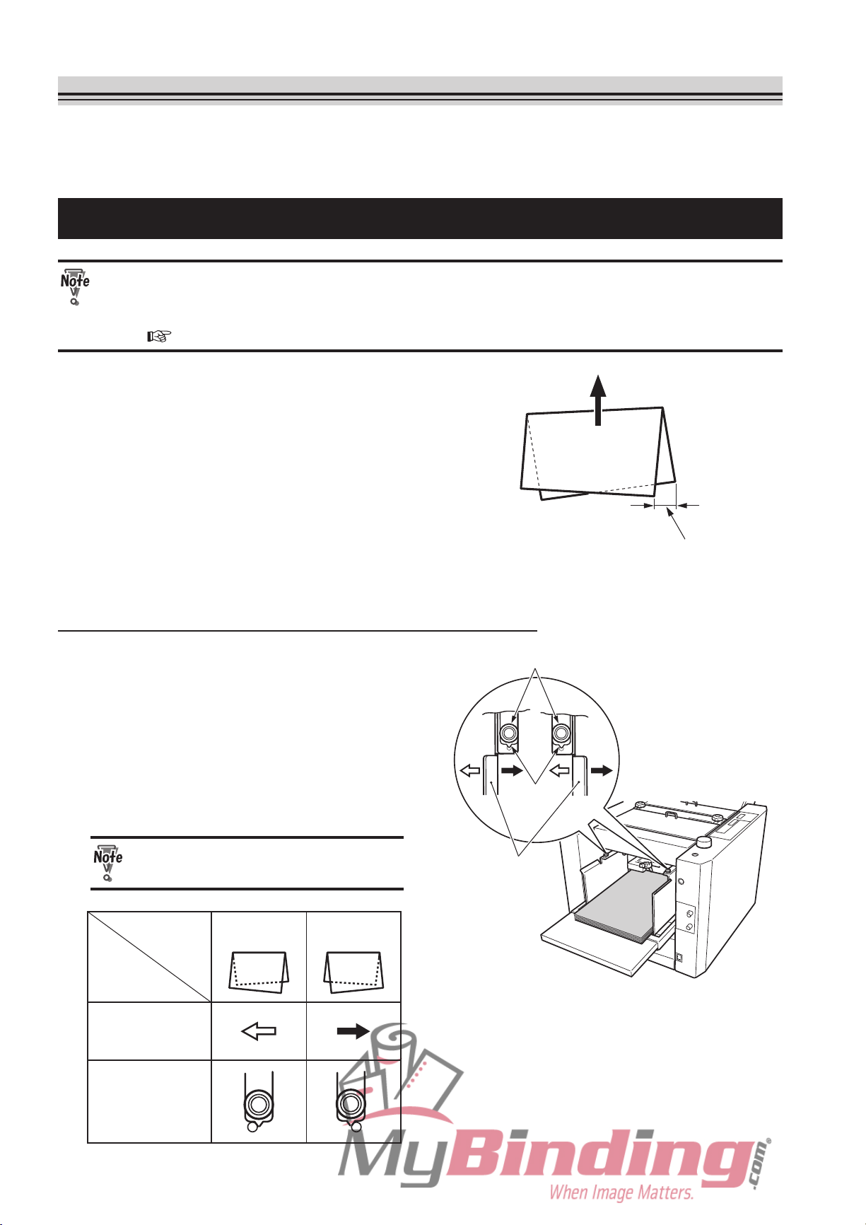
2-1. Changing the Stacker Roller Position
The position of the stacker roller is automatically set in standard folding. However, if the
alignment of paper ejected to the paper receiving tray is poor, change the position.
While pressing the stop key, press a numerical key between 1 and 7.
Stacker roller
Refer to the following table for the position for setting the stacker roller according to the folded paper length.
Numerical
key setting
1
2 To 80 B4 ........... Letter fold
3 81 to 110 A3 ........... Double fold
4 111 to 140 A4 ........... Single fold
5 141 to 170 A3 ........... Letter fold, accordion fold
6 171 to 210 A3 ........... Single fold, irregular accordion fold
Folded paper
length (mm)
Applicable standard paper size and folding mode
∗
A4 ........... Double fold
B5 ........... Irregular accordion fold
A5 ........... Irregular accordion fold
B6 ........... Double fold, letter fold, accordion fold
B4 ........... Double fold, irregular accordion fold, accordion fold
A4 ........... Irregular accordion fold, letter fold, accordion fold
B5 ........... Double fold, letter fold
A5 ........... Single fold, double fold, letter fold, accordion fold
B6 ........... Single fold, irregular accordion fold
B5 ........... Single fold, accordion fold
B4 ........... Single fold
7 211 to 250 Custom folding
∗
Use numerical key “1” if paper jams at the “2” position.
<Returning to position before change>
Press the numerical key 0 while pressing the stop key or change the folding mode.
The above procedure returns to the default position only for the setting data. Pressing
the test key or start key to start folding will move the stacker roller.
4-13
Page 63

2. ADJUSTING THE STACKER ROLLER
2-2. Changing the Stacker Roller Height
If paper jams frequently at the stacker roller in the use of thick paper, change the height of the
stacker roller.
Lift up the stacker roller.
1
Turn down the lever of the stacker
2
support in the arrow direction.
After completing folding operations,
be sure to return the stacker roller to
the original position.
Lever
Stacker roller
4-14
Page 64

3. WHEN PAPER JAMMING OCCURS
Speed 5 lamp blinks
(When set faster than speed 5)
When paper jams and operations stop, the LCD will show the location of the jam.
“JAM FEED SECT” or “FEED ERROR”
“
3-1. When Paper Jams at Paper Feed Tray” ( this page)
“JAM INSIDE” Inside unit or near folding plate
“
3-2. When Paper Jams Inside Unit” ( this page)
“JAM EXIT” Near stacker unit
“
3-3. When Paper Jams at Stacker Unit” ( p.4-18)
Near paper feed tray
3-1. When Paper Jams at Paper Feed Tray
Press the tray down button to lower
1
the paper feed tray.
Remove the jammed paper.
2
If difficult to remove, open the top cover L and
remove.
Paper
Top cover L
3-2. When Paper Jams Inside Unit
If pap er jam s fr e q u e n t l y ins i d e
the unit in the use of thick paper,
after removing the paper, set the
processing speed faster than speed
5. With the speed 5 lamp lit, press and
hold the “+” speed key for more than
three seconds, and the lamp will stop
lighting and start blinking.
Tray down button
4-15
Page 65
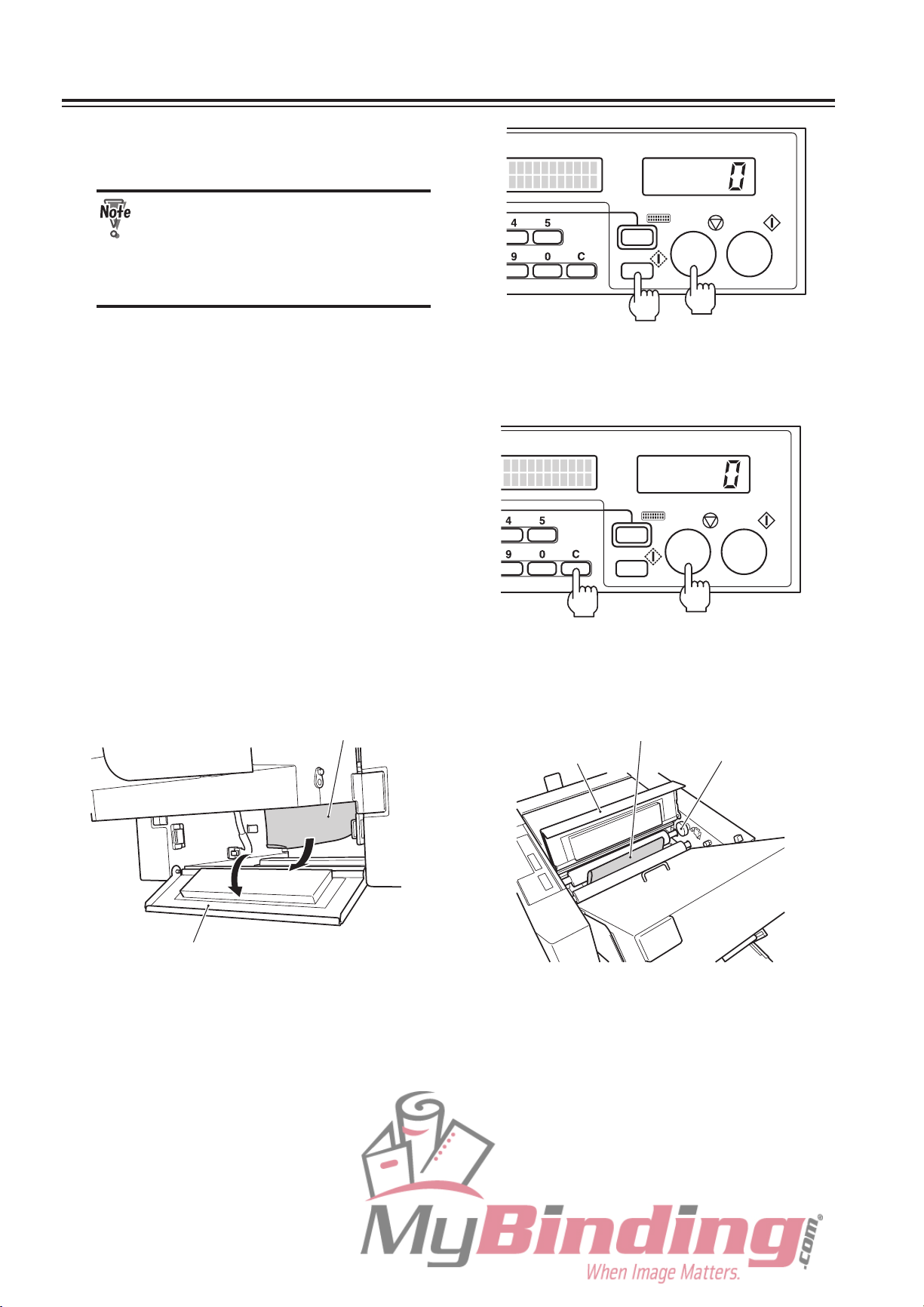
3. WHEN PAPER JAMMING OCCURS
Press the test key while pressing the
1
stop key to forcibly eject the paper.
If the error message “MOTOR
ERROR 1” is displayed on the LCD
without the unit moving, proceed
to step 3, remove the folding plate
and remove the paper.
If no paper is ejected even by forced ejection, proceed to the following step.
Press the clear key while pressing the
2
stop key to forcibly eject the paper in
the folding plate.
If no paper is ejected, open the side cover and top cover R, and remove any paper
there.
PaperPaper
Top cover R
Side cover
Jam correction knob
4-16
Page 66

3. WHEN PAPER JAMMING OCCURS
If paper near the folding rollers is difficult to remove, remove the folding plate
3
according to the following procedure and remove the paper.
1) Turn OFF the power.
Power switch
2) Disconnect the folding plate connector from
the main body.
3) Turn the lock lever towards “UNLOCK” and
remove the folding plate.
Open the top cover R, and while rotating the
4)
jam correction knob, remove the jammed
paper.
Reinstall the folding plate by the reverse
order of steps 2) and 3).
If the paper winds around the
folding roller or the jam correction
knob cannot be rotated easily,
hold the edge of the paper and
pull it out. Do not attempt to rotate
the knob by force.
Folding plate connector
Folding plate
Lock lever
Top cover R
Paper
Jam correction
knob
4-17
Page 67

3. WHEN PAPER JAMMING OCCURS
3-3. When Paper Jams at Stacker Unit
Remove the paper jammed near the
1
stacker roller.
If the paper is difficult to remove, perform the following procedure.
2
1) Loosen the two knob screws and remove the
paper ejection guide.
2) While pressing the stop key, press the test
key and forcibly eject the paper.
Paper
Paper ejection guide
3)
Reinstal l the pap er ejection g uid e to its
original position.
4-18
Page 68
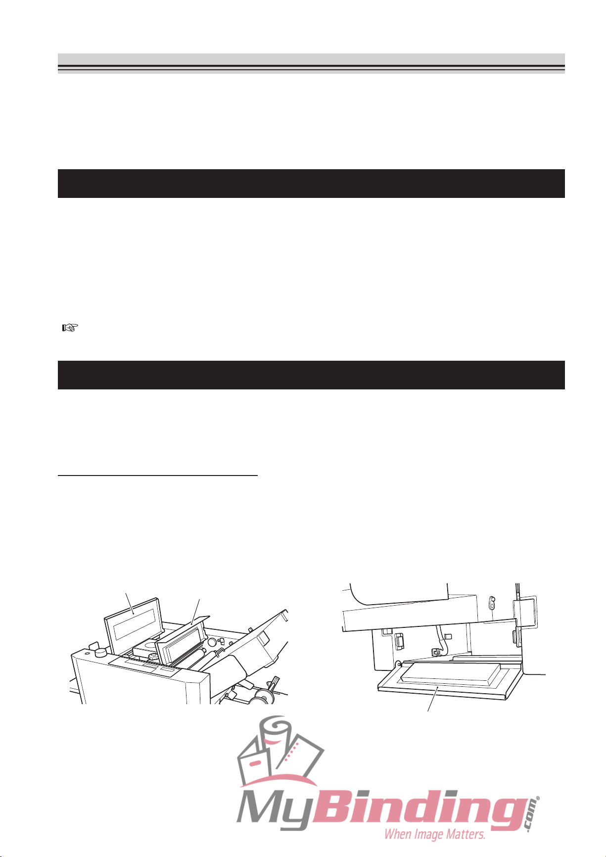
4. ERROR MESSAGES
When paper feed errors and malfunctions occur during operations, the jam location and other
details are displayed on the LCD.
Likewise,
occur.
4-1. Paper Jam Messages
The following error message will be displayed according to the jam location on the LCD.
“JAM FEED SECT”
“JAM INSIDE”
“JAM EXIT”
<Solution>
details and instructions will be displayed when operation errors and key input errors
F
or details on removing jammed paper, refer to “3. W
( p.4-15).
HEN PAPER JAMMING OCCURS”
4-2. Operation Error Messages
When covers are open or operations are not performed correctly, the following error
messages will be displayed on the LCD.
(1) When covers are open
“TOP COVER-L OPEN”
“TOP COVER-R OPEN”
“SIDE COVER OPEN”
<Solution>
Close the cover.
Top cover L
Top cover R
Side cover
4-19
Page 69
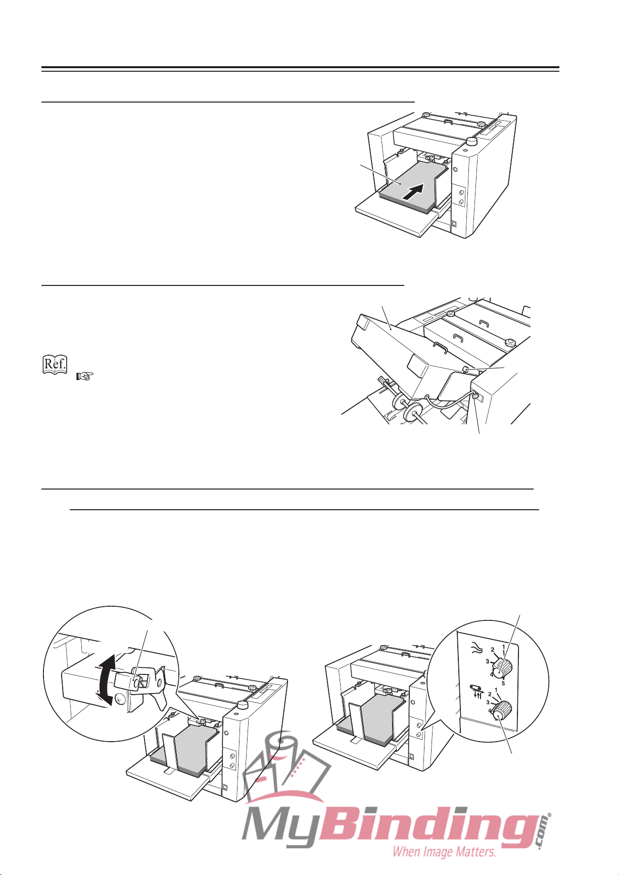
4. ERROR MESSAGES
(2) When paper runs out on the paper feed tray
“NO PAPER”
<Solution>
Stack paper on the paper feed tray.
Paper
(3) When the folding plate is not set correctly
“F.PLATE SET ERR”
<Solution>
Set the folding plate again.
“3-2. When Paper Jams Inside Unit”
p.4-15)
(
Folding plate
Lock lever
Folding plate connector
(4) When level sensor, separating air, and separator adjusting
lever and adjusting knobs are not at their correct positions
“FEED ERROR”
<Solution>
Adjust the adjusting lever and the adjusting knobs according to the paper type.
Adjust the height of the separator while checking its distance from the suction belt.
Separating air adjusting knob
Level sensor adjusting lever
“2” side
“1” side
Separator adjusting knob
4-20
Page 70

4. ERROR MESSAGES
4-3. Key Input Error Messages
When setting non-standard paper length, folding stopper position during custom folding,
and folding misalignment adjustment values, entering a value exceeding the scope of
specifications displays the following error messages on the LCD.
“TOO SHORT”
“TOO LONG”
“OUT OF CORRECT”
<Solution>
Enter a value within the scope of specifi
For details, refer to “1. STANDARD
CUSTOM FOLDING” ( p.3-5) in Chapter 3 APPLIED USE, and “1-2. Correcting Folding
Misalignment Along Vertical Length of Paper” ( p.4-5) in this Chapter.
cations.
FOLDING OF NON-STANDARD PAPER” (
p.3-2), “2.
4-4. Motor and Sensor Error Messages
When motors and sensors in the unit malfunction, the following error messages will be
displayed on the LCD.
If after turning OFF the power and implementing the following solution, and then turning
ON the power again, the same message appears again, contact your nearest dealer. Wait
for more than 30 seconds first before turning ON the power again.
(1) Main motor malfunction
“MOTOR ERROR 1”
<Cause>
The main motor is locked due to paper jamming.
<Solution>
First, turn OFF the power.
or details on removing jammed paper, refer to “3. WHEN PAPER JAMMING OCCURS”
F
( p.4-15).
4-21
Page 71

4. ERROR MESSAGES
(2) Folding motor malfunction
“MOTOR ERROR 4”
“MOTOR ERROR 5”
<Cause>
The folding plate connector is not connected properly.
The folding motor 1 or 2 is locked due to paper jamming.
<Solution>
First, turn OFF the power.
C
heck that the folding plate connector is
connected to the main body properly.
For details on removing jammed paper, refer
to “3. WHEN PAPER JAMMING OCCURS”
( p.4-15).
(3) Stacker motor malfunction
“MOTOR ERROR 3”
<Cause>
The stacker unit connector is not connected properly.
The stacker motor is locked due to paper jamming.
<Solution>
First, turn OFF the power.
pen the side cover, and check that the
O
stacker unit connector is connected to the
main body properly.
For details on removing jammed paper, refer
to “3. WHEN PAPER JAMMING OCCURS”
( p.4-15).
Folding plate connector
Stacker unit connector
4-22
Side cover
Page 72
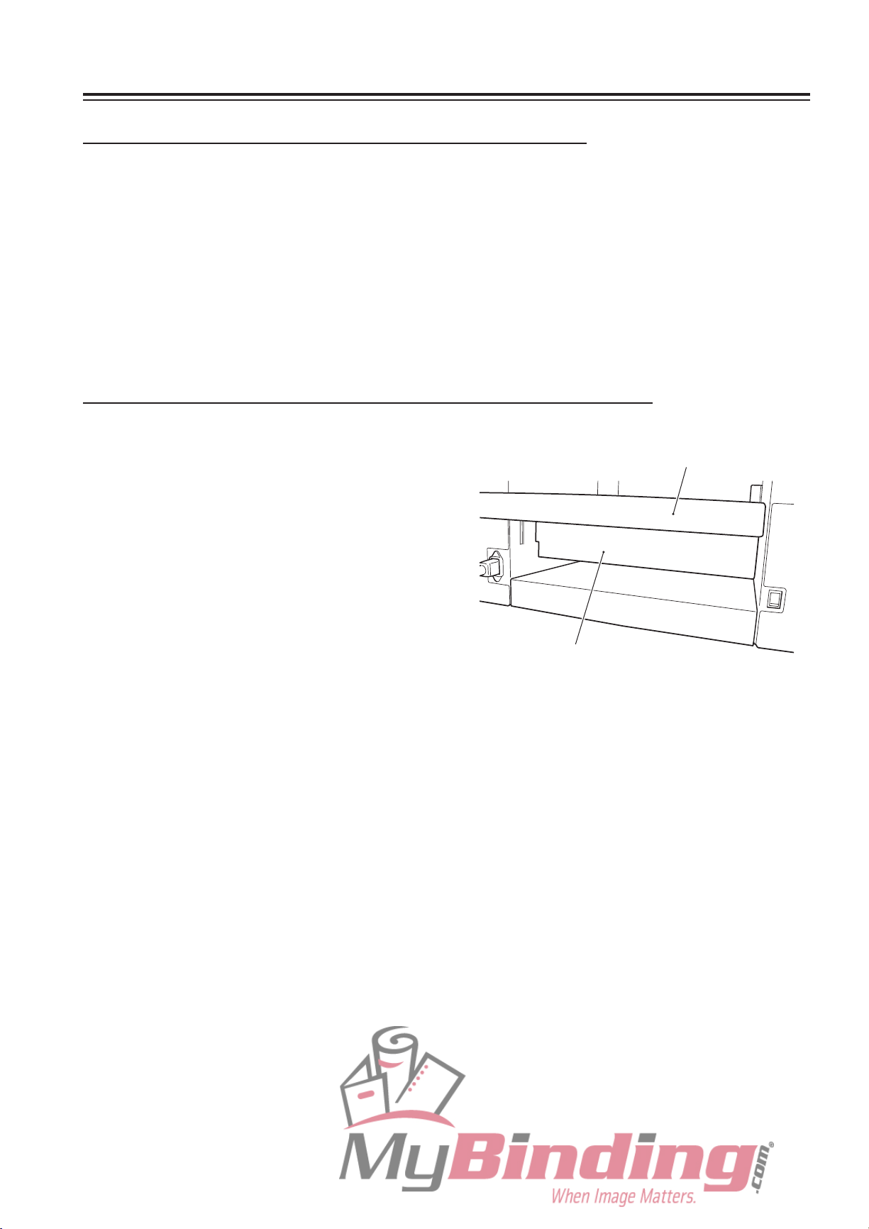
4. ERROR MESSAGES
(4) Paper feed tray malfunction (When rising)
“TRAY UP ERROR”
<Cause>
There are foreign objects between the paper feed tray and suction belt.
There is a clearance between the paper lead edge and shutter.
<Solution>
Check for foreign objects on the paper feed tray.
Stack the paper on the paper feed tray again so that the lead edge touches the shutter lightly.
(5) Paper feed tray malfunction (When descending)
“TRAY DOWN ERROR”
<Cause>
There
are foreign objects between the paper
feed tray and safety lever.
The safety lever is still pressed.
<Solution>
heck for foreign objects below the paper
C
feed tray.
Paper feed tray
Safety lever
4-23
Page 73
5. TROUBLESHOOTING
Problem Check Correct
1) The unit does not start
even w h en the star t
key is pressed.
2) T h e L C D do e s n o t
display the paper size.
3) Paper slips at the paper
feed section (mis-feed).
Is paper stacked properly on the
paper feed tray?
Has paper jammed? Remove jammed paper.
Is a cover open? Close open covers.
Is folding plate set properly? Set the folding plate properly.
Is the foldi n g pl a te c onnec t o r
disconnected?
Is the paper size displayed on the
LCD?
Is paper other than the standard
size used?
Is th ere clearance between th e
side guides and paper?
Has the paper been fanned well? Fan the paper well.
Is the paper curled? Correct the paper curl before use.
Stack paper properly.
Turn OFF the power and connect the
folding plate connector to the main
body.
Refer to section 2).
When using n on-s t anda r d paper ,
follow the procedure for non-standard
paper.
Al ign p aper neatly and s tack, then
push the side guides lightly against the
paper.
Is the suction belt dirty? Cle an wit h a cloth moistened with
alcohol.
Is the separator height too high? Adjust the separator adjusting knob to
a larger value.
Is the separating air amount too
weak?
Is the level sensor adjusting lever
set too near “2”?
A r e th e sid e gu i d e s p r e s s ed
against the paper too tightly?
Is the paper st acked exceeding
the maximum volume (about 100
mm)?
Is the thin paper feed button “ON”?
(When not using thin paper less
than 81.4 g/m2)
Is paper outside the specifications
used?
Ad just th e separ ating air adjusting
knob to a larger value.
Move t h e lev e l s e n s o r a d j u sting
lever slowly to “1” and adjust to an
appropriate value.
Set the side guides so that they push
against the paper lightly.
Decrease the paper stacked to the
scale mark on the side guide.
Set the thin paper feed button to “OFF”.
Use paper within the specifications.
4-24
Page 74

5. TROUBLESHOOTING
Problem Check Correct
4) Paper jam occurs.
5) Paper is continuously
fed or double fed.
Has the paper been fanned well? Fan the paper well.
Is the paper curled? Correct the paper curl before use.
Is the inside of the unit jammed
with paper chips, etc.?
Is the folding roller dirty? Clean w ith a cloth moist ened w ith
Has static electricity occurred in
the paper?
Is the position of the stacker roller
of th e paper ej e c t i o n s e c t i o n
correct?
Has the paper been fanned well? Fan the paper well.
Is the paper curled? Correct the paper curl before use.
Is the separator height too low? Adjust the separator adjusting knob to
Is the separating air amount too
strong?
Inspe ct the inside of the uni t, and
remove paper chips.
alcohol.
Decrease the processing speed.
Set the stacker roller at an appropriate
position.
a smaller value.
Ad just th e separ ating air adjusting
knob to a smaller value.
6) Folding misalignment
along vertical length of
paper occurs.
Is the level sensor adjusting lever
set too near “1”?
Is the paper st acked exceeding
the maximum volume (about 100
mm)?
Is the thin paper feed button “OFF”?
(When using thin paper less than
81.4 g/m2)
Is flimsy paper used? Decrease the processing speed.
Is paper outside the specifications
used?
W a s t h e p r o c e s s i n g s p ee d
changed halfway through?
Was the paper type (paper quality,
t h i c k n e s s ) chan g e d h a l f w a y
through?
Move t h e lev e l s e n s o r a d j u sting
lever slowly to “2” and adjust to an
appropriate value.
Decrease the paper stacked to the
scale mark on the side guide.
Set the thin paper feed button to “ON”.
Use paper within the specifications.
Set back the previous speed.
If the speed has been changed, the
foldi n g st o p per positi o n m ust be
corrected.
Use the original paper before change.
If paper has been changed, the folding
stopper position must be corrected.
4-25
Page 75

5. TROUBLESHOOTING
Problem Check Correct
7) Folding misalignment
along sid es of pa per
occurs.
8) Paper is no t f o l d e d
at the no rmal folding
position.
Is th ere clearance between th e
side guides and paper?
Is the side guide adjusting knob
loose?
Is the paper trimmed precisely? Correct the folding misalignment with
Are the left and right skew roller
spring pressure adjusting knobs
set at the same position?
Is the folding roller dirty? Clean w ith a cloth moist ened w ith
Is folding plate set properly? Set the folding plate properly.
Has static electricity occurred in
the paper?
Is non-stan dard p aper with the
sa me width bu t different len gth
from standard paper used?
Al ign p aper neatly and s tack, then
push the side guides lightly against the
paper.
Tighten the knob firmly.
the si de gui de adjusting k nob and
skew correction knob.
Set at the same position.
alcohol.
Fan the paper well.
Decrease the processing speed.
When using n on-s t anda r d paper ,
follow the procedure for non-standard
paper.
Are the left and right skew roller
spring pressure adjusting knobs
set at the same position?
Set at the same position.
4-26
Page 76

Chapter 5
MAINTENANCE
5-1
Page 77

1. CLEANING THE UNIT
Dirty folding rollers and suction belts can cause problems such as folding misalignment,
and paper feed errors. Adherence of paper dust near sensors will also cause misdetection.
Therefore clean periodically.
Clean the paper feed inlet sensor and paper ejection outlet sensors with canned air
recommended for computers, key boards, and similar products.
Prior to cleaning, be sure to disconnect the power cord plug from the outlet.
After cleaning, make sure that the areas that were cleaned are completely dry before
resuming paper folding operations.
WARNING
Do not use flammable sprays or solvent inside or near the unit (e.g.
when cleaning the unit).
Such flammable gas may ignite and cause a fire or combustion.
Take precautions against fire and ensure ventilation when using alcohol, and store the
alcohol in a safe place after use. Also note that use of other solvents can damage the
rubber rollers and resin inside the unit, resulting in malfunctions.
1-1. Cleaning the Folding Rollers
D i s c o n n e c t t h e f o l d i n g p l a t e
1
connector from the main body.
T u r n t h e l o c k l e v e r t o w ar ds
2
“UNLOCK” and remove the folding
plate.
Folding plate
Folding plate connector
Lock lever
5-2
Page 78

1. CLEANING THE UNIT
Open the top cover R.
3
While rotating the folding rollers with
4
the jam correction knob, clean them
with a cloth moistened with alcohol.
Return the folding plate to its original
5
position.
Turn the lock lever towards “LOCK”,
6
a n d co n n e c t th e fo l di n g pl a te
connector to the main body.
Check that the jam correction knob
7
rotates smoothly.
If the folding plate is not secured
at the correct position, the knob
will not only feel heavy, but the
folding rollers and folding plate
may get damaged.
Top cover R
Jam correction knob
Close the top cover R.
8
5-3
Page 79

1. CLEANING THE UNIT
1-2. Cleaning the Suction Belts
Prior to cleaning, move the side guides out to the sides and lower the paper feed tray.
Open the top cover L.
1
Rotate the suction belts by rotating
2
the paper feed shaft by hand. Clean
them with a cloth moistened with
alcohol.
Close the top cover L.
3
Top cover L
Paper feed shaft
1-3. Cleaning the Stacker Belts
Lift up the stacker roller, and turn
1
down the lever of the stacker support
in the arrow direction.
While rotat ing th e stacker bel ts
2
by hand, clean them with a cloth
moistened with alcohol.
Return the stacker roller to its original
3
position.
Suction belts
Stacker belts
Stacker roller
Lever
5-4
Page 80
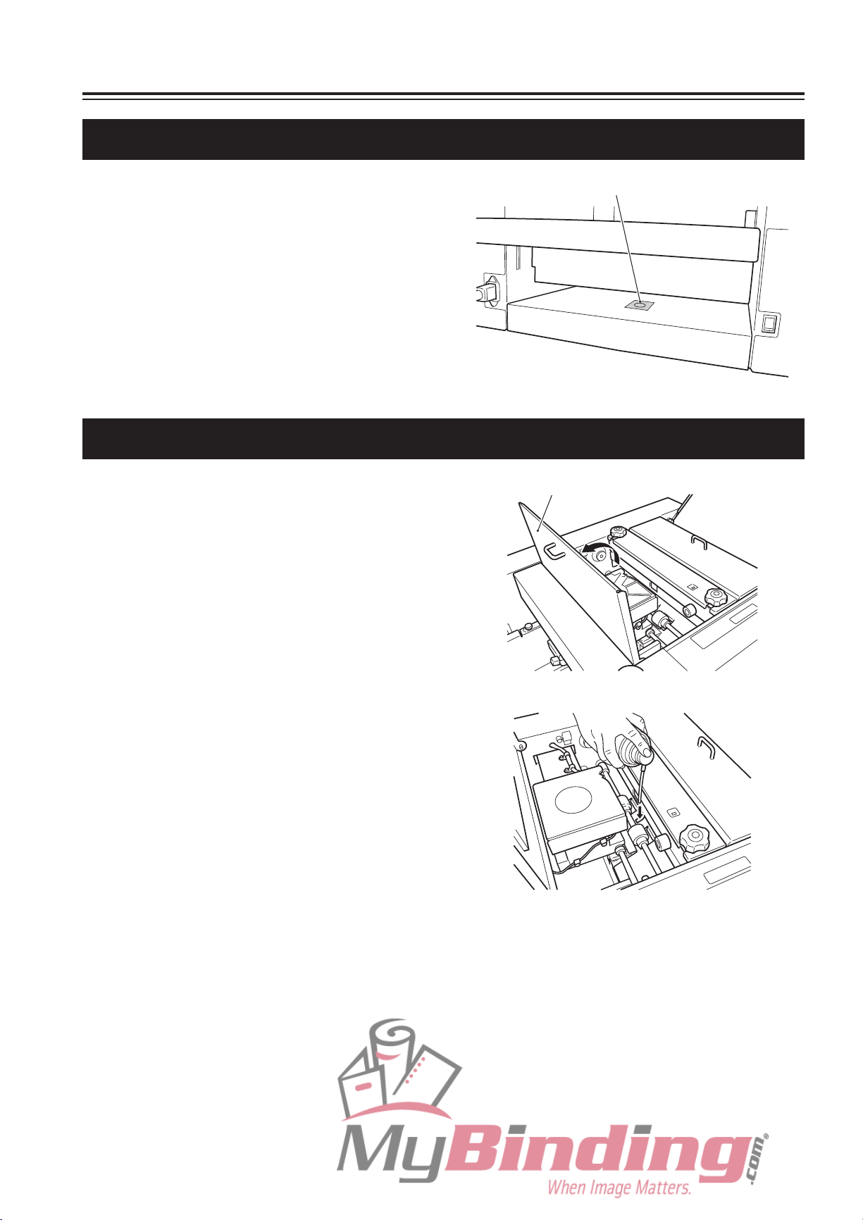
1-4. Cleaning the Paper Sensor
1. CLEANING THE UNIT
Clean the protection film of the paper
1
sensor under the paper feed tray with
a dry and soft cloth.
Protection film of paper sensor
1-5. Cleaning the Paper Feed Inlet Sensor
Open the top cover L.
1
Top cover L
Insert the nozzle of the dust removal
2
spray (canned air) into the cut-away
on the sensor cover vertically, and
blow air.
Close the top cover L.
3
5-5
Page 81

1. CLEANING THE UNIT
1-6. Cleaning the Paper Ejection Outlet Upper Sensor
Remove the folding plate and open
1
the top cover R.
For details on removing the folding
plate, refer to “1-1. Cleaning the
Folding Rollers” (
Insert the nozzle of the dust removal
2
spray (canned air) into the cut-away
on the sensor cover, and blow air.
Return the folding plate to its original
3
position.
p.5-2).
Top cover R
Folding plate
Lock lever
Close the top cover R.
4
1-7. Cleaning the Paper Ejection Outlet Lower Sensor
Loosen the two knob screws and
1
remove the paper ejection guide.
Paper ejection guide
Insert the nozzle of the dust removal
2
spray (canned air) into the cut-away
on the sensor cover, and blow air.
Reinstall the paper ejection guide to
3
its original position.
5-6
Page 82

Appendix
A-1
Page 83

1. SPECIFICATIONS
Model DF-1000
Type For office use/desktop
Paper size Max. 297 (W) × 432 (L) mm (Along paper feed direction) ∗ Maximum paper width: A3
Min. 120 (W) × 182 (L) mm (Along paper feed direction)
Paper quality Fine quality paper, recycled paper, art paper, coated paper
Folding mode Single
custom fold
∗
Paper weight Fine quality paper, recycled paper
Art paper, coated paper : 73.3 to 157 g/m
∗
Paper feed tray capacity 1000 sheets (fi
Maximum processing
speed
Paper feed method Air suction paper feed method
Paper feed tray control
function
Paper size detection
function
Paper feed error
detection function
200 sheets/minute
Condition: When 64 g/m
Paper
possible)
A
(fed by short edge feeding)
Mis-feed, continuous-feed, paper jam
fold, double fold, irregular accordion fold, letter fold, accordion fold, other
However, when double folding B6 size paper, use fine quality paper of 64 g/m
set the processing speed above speed 4, and set the folded plane length of
folding plate 2 to more than 47 mm.
However, when single folding art paper or coated paper width less than 216
mm, paper up to 209.4 g/m
ne quality paper 81.4 g/m2)
presence detection, automatic rise/descent (manual raising/lowering also
utomatic detection of following standard paper sizes: A3, B4, A4, B5, A5, and B6
2
can be used.
2
A4 size fine quality paper is single folded
: 52.3 to 157 g/m
2
,
2
2
Counter 4-digit, selection of add or subtract count method
Other detection
functions
Additional functions F
Energy saving functions LCD backlight automatic OFF
Power supply 100 to 240 V AC
Current consumption 2 to 1 A (140 W)
Dimensions In use 1,277 (W) × 534 (D) × 590 (H) mm
In storage
Mass (Weight) 71 kg
Specifi
cations and dimensions are subject to change without prior notice for improvements.
O
pening/closing of top cover L/R and side cover, with/without folding plate, paper
feed tray UP/DOWN error
Various operational guidance including error messages are displayed on the
LCD
olding stopper position adjustment registration (30 ways), custom folding
registration (2 ways), non-standard paper length registration, interval, last time
fold, folding stopper fixed, thick paper supported, forced paper ejection, forced
paper ejection in folding plate, stacker belt continuous rotation
50/60 Hz
912 (W) × 534 (D) × 590 (H) mm
A-2
Page 84

Memo
A-3
Page 85

Duplo building, 1-6, Oyama 4 chome, Sagamihara,
Kanagawa 229-1180, Japan
TEL: +81-42-775-3602
FAX: +81-42-775-3606
E-mail: info@duplo.com
This manual is printed on recycled paper to help protect the environment.
12T-90051-06010020M-0
 Loading...