

Page 1

Instruction Manual
Duplo DC-645
(Slitter / Cutter / Creaser)
Version. 2 / March 2005
Correct operation and periodic maintenance are
essential for ensuring safe use of this machine.
Thoroughly read this manual before using this
machine.
Page 2

○○○○○○○○○○○○○○○○○○○○○○○○○○○○○○○○○○○○○○○○○○○○○○○○○○○○○○○○○○○○
Introduction
DC-645
Thank you for your purchase of the Duplo DC-645 (Slitter / Cutter / Creaser).
To ensure safe and efficient prolonged use of this machine, read and thoroughly understand this manual before
using this machine. After using this manual, be sure to keep it in a handy place to reference.
1
2
OVERVIEW
The DC-645 was created to produce high-quality, customized products; greeting cards, postcards, brochures,
business cards, and resized photographs. It does this by combining a number of devices that set up automatically to slit, cut, and crease a sheet of paper into the desired format with no operator intervention.
Initially, the DC-645 is manually programmed with the required positions of the slits, cuts and creases and the
values are stored in a memory for future recall. A CCD sensor reads the job number encoded in a barcode on
the unfinished sheet. Then, the DC-645 recalls the values from memory, sets up the slitter positions, activates
the cutter for lead, trail, and any intermediate cuts and any required creases.
In addition, when a small 90-degree angle register mark has been printed adjacent to the barcode, the position
is measured against the intended position stored in the job memory. As this mark is part of the original image,
any error in its location can be compared with the stored value and used to correct the setup positions of the
devices by applying a horizontal offset to the cut and crease positions, and a vertical offset to the slit positions
to maintain precise finishing every time.
PLEASE NOTE
In the interest of upgrading our products, specifications and other data given in this manual are subject to
change without notice. If the manual contains anything that you do not understand, contact the dealer for
clarification.
Trademarks
• Apple and Macintosh are trademarks of Apple Computer, Inc., registered in the U.S. and other countries.
• Windows is the registered trademark of Microsoft® Corporation.
All other trademarks are the property of their respective holders.
1
Page 3

○○○○○○○○○○○○○○○○○○○○○○○○○○○○○○○○○○○○○○○○○○○○○○○○○○○○○○○○○○○○
Contents
Introduction ......................................................................................................................... 1
DC-645 ....................................................................................................................... 1
Notes on Safety (Please Read and Observe) ................................................................... 4
Safety Precautions ............................................................................................... 4
Warning Sticker .......................................................................................................... 7
Positioning the Machine ............................................................................................. 8
Maintenance ............................................................................................................... 9
Conventions Used in This Manual ............................................................................ 10
Chapter 1 Before Using This Machine
Part Names and Their Functions ..................................................................................... 11
Appearance .............................................................................................................. 11
Modules .................................................................................................................... 13
Control Panel ............................................................................................................ 14
LCD Panel ................................................................................................................ 15
Turning Power ON/OFF .................................................................................................... 16
Turning ON the Power .............................................................................................. 16
Turning OFF the Power ............................................................................................ 17
How to Connect the DC-645 to your Computer ............................................................. 18
Before Preparing Document ............................................................................................ 19
Definition of Programming Terms ............................................................................. 20
Chapter 2 Program JOB for DC-645 Via Computer (JOB Creator)
What is JOB Creator? ...................................................................................................... 29
Installing JOB Creator ...................................................................................................... 29
Before Installation ..................................................................................................... 29
Installing Procedures (Windows) .............................................................................. 30
Installing Procedures (Macintosh) ............................................................................ 32
Uninstall and Update JOB Creator .................................................................................. 33
Uninstalling Procedures (Windows) ......................................................................... 33
Uninstalling Procedures (Macintosh)........................................................................ 34
Updating Drivers....................................................................................................... 34
JOB Creator Settings ....................................................................................................... 35
Main Menu ................................................................................................................ 35
Creating JOB with Preview Display (“Using Program Entry Wizard”) ....................... 36
Creating a JOB By Direct Number Input (“Direct Program”) .................................... 43
Reading JOB from DC-645 (“Upload Job Data from DC-645”) ................................ 45
JOB Saved on Computer Registered On DC-645
(“Download Job Data to DC-645”) ............................................................................ 47
Setting Frequent Functions From Computer (“Function Setting”)............................. 49
Create a File Recording the DC-645 Maintenance Information
(“Upload Maintenance Data from DC-645”) ............................................................. 51
List of Messages ............................................................................................................... 52
2
Page 4

○○○○○○○○○○○○○○○○○○○○○○○○○○○○○○○○○○○○○○○○○○○○○○○○○○○○○○○○○○○○
Contents
Chapter 3 Programing JOB for DC-645 on Control Panel
Prior to Programming a Job ............................................................................................ 54
Customer Programmed Jobs .......................................................................................... 56
How to Program Job on Control Panel ........................................................................... 57
Chapter 4 Basic Operations
Process Documents by Selecting JOB........................................................................... 64
Automatic Set Up Using Barcodes ................................................................................. 68
Adjust Feeder .................................................................................................................... 70
Elevator level (Feed tray) .......................................................................................... 70
Separator .................................................................................................................. 70
Airflow ....................................................................................................................... 71
Print Image Skew ..................................................................................................... 71
Curled Document / Light Weight Document ............................................................. 71
FUNCTION Mode ............................................................................................................... 72
About the Waste Box ........................................................................................................ 74
Clean Feed Rollers ........................................................................................................... 75
Chapter 5 Troubleshooting
Troubleshooting Flow Chart ............................................................................................ 76
Power Does Not Turn ON ......................................................................................... 76
Cutting is Not Possible ............................................................................................. 77
OK Monitor Display and Jam Display ............................................................................. 78
Error Display ..................................................................................................................... 80
Warning Display................................................................................................................ 82
When a Paper Jam Has Occurred ................................................................................... 83
When “REJECT PAPER” is Displayed ...................................................................... 83
When “FEED JAM” is Displayed ............................................................................... 85
When “CENTER JAM” is Displayed.......................................................................... 87
When “CUTTER OR CREASE” is Displayed ............................................................ 89
When “OPTION AREA JAM” is Displayed ................................................................ 93
When “STACKER JAM” is Displayed ........................................................................ 95
When “OVER CAPACITY” is Displayed .................................................................... 97
When “REJECT AREA JAM” is Displayed................................................................ 98
1
2
Appendix
Specifications ................................................................................................................. 100
DC-645 Specifications ............................................................................................ 100
Index ................................................................................................................................ 102
3
Page 5

○○○○○○○○○○○○○○○○○○○○○○○○○○○○○○○○○○○○○○○○○○○○○○○○○○○○○○○○○○○○
Notes on Safety (Please Read and Observe)
Safety Precautions
Various symbols and pictures are used in this manual and on the stickers affixed to the machine. These symbols and
pictures provide warnings and instructions to prevent danger to you or other personnel, and to prevent damage to office
property. The meanings of these symbols and pictures are explained below.
WARNING
CAUTION
[Examples of Pictorial Symbols]
• These are particularly important safety points and should always be observed.
Indicates a high degree of potential danger. If the warning is ignored, death or serious
injury may result.
Indicates a medium degree of potential danger. If the caution is ignored, medium injury or
damage to property may result.
A circle with a line through it indicates a prohibited action. The particular act prohibited is indicated by a picture inside the circle. (In the example shown here, the prohibited
act is disassembly.)
A black disc indicates an instruction, or sometimes a prohibited action. The
instruction itself is indicated by pictorial symbols drawn in white on the disc. (In the
example shown here, the instruction is “Remove the plug from the outlet.”)
Precautions for Use
WARNING
If the machine is used after foreign matter (metal fragments, water, or liquid) has entered the
machine, this may result in fire or electric shock.
• Turn the main unit’s power switch OFF, and then remove the power plug from the outlet.
Contact the sales distributor.
If the machine is used after heat, smoke, strange smell, or other abnormality is detected, this may
result in fire or electric shock.
• Turn the main unit’s power switch OFF, and then remove the power plug from the outlet.
Contact the sales distributor.
Do not insert or drop metal, flammable material, or other matter through the ventilation holes into
the machine interior.
• Doing so may result in fire or electric shock.
Do not place flower vases, flowerpots, cups, or water containers (including metal containers) on top
of the machine.
• Fire or electric shock may result if liquid spills inside the machine.
4
Page 6

○○○○○○○○○○○○○○○○○○○○○○○○○○○○○○○○○○○○○○○○○○○○○○○○○○○○○○○○○○○○
Notes on Safety (Please Read and Observe)
Caution for Grounding (Be sure to use the supplied power cord)
WARNING
Use only the power cord that is provided among the accessories.
Insert the power cord plug firmly into the socket, so that proper electrical contact is effected.
• Use of any other power cord could result in imperfect grounding.
If grounding is imperfect and electrical leakage occurs, fire or electric shock could result.
Caution for Power Supply and Power Cord
WARNING
Do not use a source voltage other than that specified. Do not connect two or more loads to a single
outlet.
• Doing so may result in fire or electric shock.
Do not remove or insert the power plug with wet hands.
• Doing so may result in electric shock.
1
2
Do not damage, break, or modify the power cord.
Do not place heavy objects on, tug, or unnecessarily bend the power cord.
• Doing so may result in fire or electric shock.
CAUTION
Remove the power plug itself, not the cord.
• Tugging the cord may damage it (expose conductors, or cause disconnections, etc.), resulting in
fire or electric shock.
5
Page 7

○○○○○○○○○○○○○○○○○○○○○○○○○○○○○○○○○○○○○○○○○○○○○○○○○○○○○○○○○○○○
Notes on Safety (Please Read and Observe)
Prohibition of Disassembly or Modification
WARNING
Do not modify the machine.
• Doing so may result in fire or electric shock.
Do not remove the rear lid, cabinet, or covers from the machine.
• The inside of the machine contains high-voltage parts, which may cause electric shock.
Caution for Location
Do not move this machine by yourself.
• Please contact your service person when you wish to move the machine.
(Fine adjustment is required.)
Do not place the machine in a place subject to direct sunlight or heating equipment such as a stove.
• It may degrade ink quality and affect printing.
The machine also may malfunction.
Avoid placing the machine in a place subject to high or low temperature or high humidity.
• The paper absorbs moisture and it may cause paper jam or wrinkles.
WARNING
CAUTION
6
Page 8

○○○○○○○○○○○○○○○○○○○○○○○○○○○○○○○○○○○○○○○○○○○○○○○○○○○○○○○○○○○○
Notes on Safety (Please Read and Observe)
Warning Sticker
Keep the WARNING stickers clean at all times. If stickers become damaged or come off, replace them with new ones.
1
2
1
1
WARNING
1
Cutters and movable parts are inside this cover.
Before opening the cover to work,
unplug the power cord.
Use caution when working near cutters
and movable parts.
L8-T1080
2
2
2
WARNING
DO NOT put hands inside machine
while it is operating.
Hands could get caught up
or crushed.
No. Parts No. Name Q’ty
1 L8-T1080 Warning Sticker 1 2
2 M7-T3030 Warning Sticker 2 2
M7-T3030
7
Page 9

○○○○○○○○○○○○○○○○○○○○○○○○○○○○○○○○○○○○○○○○○○○○○○○○○○○○○○○○○○○○
Notes on Safety (Please Read and Observe)
Positioning the Machine
Installing the machine on a flat, stable surface.
Avoid installing the machine in a dusty area.
Avoid installing the machine in the direct sunlight or heat,
such as near a stove. The machine may indicate errors due
to overheating caused by sunlight. Also avoid hot, cold, or
humid areas since paper may absorb moisture, causing
paper jams or wrinkles.
8
Page 10

○○○○○○○○○○○○○○○○○○○○○○○○○○○○○○○○○○○○○○○○○○○○○○○○○○○○○○○○○○○○
Notes on Safety (Please Read and Observe)
Maintenance
Clean the exterior of the machine as described below.
Tightly wring a soft cloth that has been moistened with
water or neutral detergent, and wipe dirt from the machine’s surface.
Never use alcohol or organic solvents. Doing so may
discolor or damage the machine exterior.
Dust and clean the machine at least once a week to avoid
breakdowns.
Before cleaning, turn the power switch OFF, and then
remove the power plug from the outlet.
1
2
WARNING
• Before cleaning, remove the power plug from the outlet.
Failure to do so may result in an electrical shock or a fire hazard.
• Prevent water and neutral cleansers from getting inside the machine. If liquids spill inside the machine,
contact your agent immediately. Using the machine with water spilled inside may result in an electrical
shock or a fire hazard.
9
Page 11

○○○○○○○○○○○○○○○○○○○○○○○○○○○○○○○○○○○○○○○○○○○○○○○○○○○○○○○○○○○○
[
SELECT
]
05:DUPLO
06:DUPLO 1
BC REG AC
∗ ∗ ∗
Notes on Safety (Please Read and Observe)
Conventions Used in This Manual
Each page of descriptions in this manual of how to operate the DC-645 is set up as follows.
Chapter
Title
Description of operational steps
Each step is described in detail.
Illustrations
The illustrations provide a visual
reference to which keys to operate
and other related conditions.
Chapter
4
Basic Operations
This chapter describes the operating sequence from turning ON the power switch until completing
finishing process.
Process Documents by Selecting JOB
This section describes the procedures to process documents by selecting each JOB manually.
○○○○○○○○○○○○○○○○○○○○○○○○○○○○○○○○○○○○○○○○○○○○○○○○○○○○○○○○○
Turn ON the power. (
○○○○○○○○○○○○○○○○○○○○○○○○○○○○○○○○
Press the <MODE> key and go to the
[SELECT] display.
○○○○○○○○○○○○○○○○○○○○○○○○○○○○○○○○○○○○○○○○○○○○○○○○○○○○○○○○○
Input the number of the JOB to call up, using the <Number> key.
○○○○○○○○○○○○○○○○○○○○○○○○○○○○○○○○
Press the <SET> key to call up the JOB of
the number input.
How to execute batch counting
• The specified number of document are processed.
Select or input a job and then press the <Number> key in
standby state (excluding SELECT/INPUT display) to input the
number of document for batch counting. (The specified
number of document is displayed in the lower right portion of
the control panel.)
∗ ∗
100/100
(Ex.: When 100 documents are set, the above display appears.)
By pressing the <START> key, processed number of the
document is subtracted from the specified number as below.
∗ ∗
99/100
* If an error has occurred during processing, batch counting can not be executed.
aa
a P.16 “Turning ON the Power”)
aa
∗ ∗
98/100
F
■ Pictorial Symbols and Other Notations Used in This Manual
IMPORTANT : Introduces instructions for correct operation of the machine. If these instructions are ignored,
the machine may not be able to operate at optimum performance or may break down.
Tip : Introduces information that is useful for operation and maintenance of the machine, or
information about the machine’s performance, etc.
Continue Page
•••
: Indicates that the description of the operating sequence is continued on the next page.
(a P.00 “xxxx”) : Indicates the page number and item containing related information.
10
64
Page 12

Chapter 1
Before Using This Machine
This chapter contains essential information you should understand such as how to set up the system, the
names of the machine parts, etc.
Part Names and Their Functions
Appearance
11
11
Before Using This Machine
5
6
7
8
9
4
10
11
3
No. Name Function
1 Control panel Displays operations and statuses.
2 Waste box Receives pieces of waste paper.
3 Front cover Open to remove pieces of paper in the waste box.
4 Stacker tray Receives the finished document.
5 Scale This measures the cut and slit position, and the finish of the document.
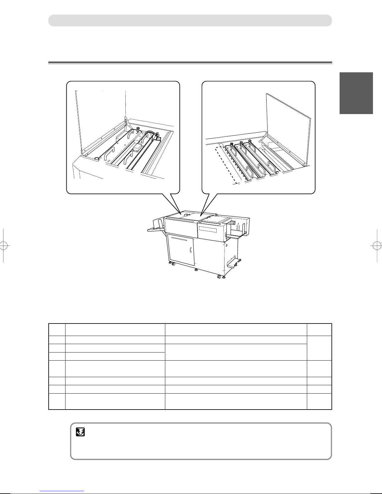
6 Top cover 3 Open this to remove the paper jam from the cutter/crease/optional module or
7 Top cover 2 Open this to remove the paper jam from the slitter module.
8 Top cover 1 Open this to move the upper guide or to remove the paper jam from the feed
9 Feed tray The original document is placed here.
10 USB terminal Insert a USB cable here to connect the computer and this machine.
11 AC inlet Connect the power cord.
12 Reject tray This is where the document comes when it is rejected due to double feed,
13 Power switch Press to switch the power on and off.
2
to replace the optional module.
unit.
barcode error, REG. Mark error, etc.
1
13
12
Reference
page
14
74
78,82
66,69
—
89 – 94
87,88
75,
85 – 86
70,97
18,31
16
81,99
16,17
11
Page 13

Part Names and Their Functions
17
16
1514
No. Name Function
14
12
Airflow adjustment knob
15
Separator adjustment knob
16
Level adjustment knob
17
Skew adjustment wheel
This adjusts the airflow level.
This adjusts the distance between the separator and document.
This adjusts the elevator height.
This adjusts the feed angle of the document.
Reference
page
71
70
70
71
Page 14
Modules
Part Names and Their Functions
11
Before Using This Machine
7
No. Name
1 Slitter Module A
2 Slitter Module B
3 Slitter Module C
4 Gutter Deflector
5 Cutter Module
6 Creaser Module
7 Transport Module
(or Optional Module)
6
5
1
2
3
4
Function
Cuts off the blank-area of the further-side and front-side.
Cuts parallel in the paper feed direction.
The blank-area cut off by the slitter is dropped in the
waste box.
Cuts in a right angle in the paper feed direction.
Creases parallely in the paper feed direction.
Transports the paper to the stacker tray.
Reference
page
19,54,
80,82
36,37,
72,81
54,79,80,89
54,79,81,89
36,57
IMPORTANT
• When removing various modules of this device, always re-set the module in the sequential
order indicated in the illustration above. It is especially that the slitter module is properly
assembled, when setting slitter module A, B and C again.
13
Page 15

Part Names and Their Functions
Control Panel
123
71011456
8 9 12 13
No. Name Function
1 OK Monitor The LED of the Error area flashes when detecting an Error.
2 LCD panel Displays the status of the machine.
Displays the message when an error or paper jam occurs.
3 < + / – > key Select setting of function.
4 <F> key Switches to function selecting display.
5 <MODE> key Switches modes. (operating mode, JOB selectiong mode, JOB inputing mode)
6 <SET> key Press to confirm selection / entry.
7 POWER lamp Lights up when the power is switched on.
8 <CLEAR> key Press to clear the count. Press to cancel manual programming.
9 <Number> key Press to enter print numbers and enter values during manual programming.
10 •
11 <TEST> key One (sheet) document is processed to test the current JOB details.
12 <START> key Press this to start processing the document. The <START> key light
13 <STOP> key Press to stop automatic feeding after the current sheet is processed.
<JOG> keys
Press to eject the document from the machine when paper jam occured.
turns green when the machine is ready to process the document in this
machine. The <START> key can be activated when the LED on the key
is green. The <START> key is inactive when the light is red. In this
case DC-645 may be running or having an error.
Reference
page
78,79
15,
80 – 82
58 – 63,72,73
73
58,64,75
58 – 63,73
—
—
58,59,64
58,59,83 – 98
—
64,66,69
67,78 – 82,
85 – 99
14
Page 16

LCD Panel
Part Names and Their Functions
12
∗ ∗ :
BC REG AC
∗∗ ∗ ∗ ∗ ∗ ∗ ∗ ∗ ∗ ∗ ∗ ∗
∗ ∗ ∗
345 6
No. Name Function
1 JOB No. Displays the JOB No. currently selected.
2 JOB name Displays name of the JOB currently selected.
3 BARCODE BC is displayed when barcode reading is ON.
4
REGISTER MARK
5 AUTO CUT AC is displayed when AUTO CUT is ON.
6 COUNTER The number of document sheets processed with the JOB currently set, is
REG is diaplayed when REG. Mark reading is ON.
displayed.
Reference
page
36,58,64
36,58
37,72
37,72
37,55,72
64
11
Before Using This Machine
15
Page 17

Turning Power ON/OFF
This section describes the operating sequence from turning ON the power switch until the machine is ready to operate,
and how to turn OFF the power.
Turning ON the Power
○○○○○○○○○○○○○○○○○○○○○○○○○○○○○○○○
Connect the “female plug” of the power cord to
the “inlet”.
○○○○○○○○○○○○○○○○○○○○○○○○○○○○○○○○
Connect the “male plug” of the power cord to
the “outlet”.
○○○○○○○○○○○○○○○○○○○○○○○○○○○○○○○○
Press the “ | ” side of the power switch.
The power turns ON.
The illustration on the right shows what is displayed on the
LCD panel.
The illustration on the right shows that paper remains in the
machine. If this screen is displayed, remove them.
(a P.83, “When “REJECT PAPER” is Displayed”)
∗ ∗:∗∗∗∗∗∗∗∗∗∗
BC REG AC
∗∗∗
––– J 1 –––
REJECT PAPER
16
Page 18

Turning OFF the Power
○○○○○○○○○○○○○○○○○○○○○○○○○○○○○○○○
Press the “
The power turns OFF.
KK
K ” side of the power switch.
KK
Turning Power ON/OFF
11
Before Using This Machine
17
Page 19

How to Connect the DC-645 to your Computer
Prepare USB 2.0 Cable (A/B 4-pin).
Plug the type B connector into the DC-645 and the type A connector into the USB slot on your computer.
Computer
USB 2.0 Cable
18
Page 20

Before Preparing Document
Familialize your self with the following illustrations and instructions to make your documents appropriately.
DC-645 has six slitters. Two slitters are for the margins and the remaining four slitters are for the center of the
document.
There is a guillotine cutter that performs cuts perpendicular to the paper feeding direction. DC-645 can cut up to 15
cuts on 1 document.
There is a creaser that performs creases perpendicular to the paper feeding direction. DC-645 can crease up to 10
creasing on 1 document.
Paper and Processing Position
9
...CREASE
1
1
35
7C B A8910
...SLIT1
3
...SLIT3
5
...SLIT5
6
...SLIT6
11
Before Using This Machine
No. Name
1 Slitter 1 (in Slitter Module A)
2 Slitter 2 (in Slitter Module A)
3 Slitter 3 (in Slitter Module B)
4 Slitter 4 (in Slitter Module B)
5 Slitter 5 (in Slitter Module C)
6 Slitter 6 (in Slitter Module C)
7 Gutter Deflector
8 Cutter Module
9 Creaser Module
10 Transport Module
(or Optional Module)
Feed
direction
246
8
...CUT
Function
Cuts off the blank-area of the further-side and front-side.
Cuts off the blank-area of the front-side.
Cuts parallel in the paper feed direction.
Cuts parallel in the paper feed direction.
Cuts parallel in the paper feed direction.
Cuts parallel in the paper feed direction.
The gutter strips cut off by slitters are dropped into the
waste box.
Cuts in a perpendicular to the paper feed direction.
Creases parallely in the paper feed direction.
Transports the paper to the stacker tray.
4
...SLIT4
2
...SLIT2
Reference
page
60,80,82
61,80,82
40,81
54,79,80,89
54,79,81,89
36,57
IMPORTANT
• When removing various modules of this device, always re-set the module in the sequential
order indicated in the illustration above. It is especially that the slitter module is properly
assembled, when setting slitter module A, B and C again.
19
Page 21

Before Preparing Document
Definition of Programming Terms
PAPER FEEDING DIRECTION
Barcode
(Optional)
SLIT 2
SLIT 4
SLIT 6 SLIT 5
PAPER FEEDING DIRECTION
REG. Mark
(Optional)
SLIT 1
SLIT 3
First Cut
Last cut
20
REG. Mark
(Optional)
Barcode
(Optional)
Crease
(CRE. 01)
Page 22

Slit / Cut / Crease Limitations
There arer limitations for slit / cut / crease process on DC-645.
Before Preparing Document
CUT1
CREASE1
Paper feed direction
Slit: Up to 6 slits are possible on 1 document.
Cut: Up to 15 cuts are possible on 1 document.
Crease: Up to 10 creases are possible on 1 document.
SLIT2
SLIT4 SLIT6 SLIT5 SLIT3 SLIT1
11
Before Using This Machine
Lead margin:
3.2mm ~
Card length:
85mm ~
CUT2
CUT3
CREASE2
CUT4
Left margin:
3.2mm~40mm
from left edge
Card width:
48mm~
Gutter slit :
5-15mm
Trail margin:
5mm ~
Right margin:
3.2mm~40mm
from right edge
21
Page 23

Before Preparing Document
REG. Mark (Registration mark)
DC-645 automatically compensate for image drift, one of the common problems on digital printers. It detects
the image drift caused on each page by reading REG. mark with built-in CCD and adjust the cut / slit / crease
position accordingly.
To use this function, each documents must have REG, mark printed on them. Please refer to following
instructions for specifications and position of REG. mark.
1) Specifications
REG. mark consists of 2 straight & perpendicular lines.
line length : 5 mm or more / each
line thickness : 0.4 mm or more / each
Paper feed direction
Lead mark
Correct for image drift
in this direction
Correct for image drift
Side mark
in this direction
Use pen tool etc. of your software application to draw 2 straight & perpendicular lines.
2) Position
Paper feed direction : The whole REG. mark should be within 3 mm ~ 20 mm from the lead edge.
Paper width direction : The whole REG. mark should be within 3 mm ~ 20 mm from the right edge.
3mm
3mm
5mm or more
5mm
or more
20mm
22
0.4mm or more
REG. Mark
Position Range
REG. Mark
Page 24

BARCODE
By adding barcode which indicates job number on each document, DC-645 automatically set up the machine
and start the job. Operator can press the START key and leave. Even if multiple types of jobs are loaded on the
feed tray at one time, DC-645 recognizes barcode on documents also with the built-in CCD and automatically
switch setup and finish the jobs.
Before Preparing Document
To use this function, each documents must have BARCODE printed on them. Please refer to following
instructions for specifications and position of BARCODE.
1) Specifications
Barcode type : CODE-39
Start and Stop code : Required
Check digit : Optional
Minimum resolving power : 0.254 mm
Thin bar : Thick bar : 1 : 2.5
Bar height : 4 mm or more
Use barcode generator function equipped on your software application or use barcode generator software.
2) Position
Paper feed direction : The whole BARCODE should be within 3 mm~ 20 mm from the lead edge.
Paper width direction : The whole BARCODE should be within 25 mm~60 mm from the right edge
(See below)
q is the start code designator for CODE-39.
w is the 10’s digit data of the JOB number.
(Example: When the
JOB
number is 21, the data is “2”.)
Paper feed direction
11
Before Using This Machine
e is the 1’s digit data of the JOB number.
(Example: When the
r is the check digit.
t is stop code of CODE-39.
POSITIONING THE BARCODE
5 mm
JOB
number is 21, the data is “1”.)
60 mm
10 mm
NON PRINTING AREA
*24*
2
1
3
5
4
23
Page 25

Before Preparing Document
How to Make a Barcode for Use DC-645
The easiest way to create the code is with a TrueType Font. Fonts are readily available from many companies on the
internet. Here are two companies which have fonts suitable for use with the DC-645 (there are many companies offering
fonts).
www.barcodetrader.com/bct_scan_barcode.asp
http://www.squaregear.net/fonts/
Free download of Barcode creating software.
http://www.datascan.co.uk
Samples - standard font Price £149 for a single user; £298 for 2 – 5
*The above is only an example of a homepage.
*The above is a general homepage. Note that it may be ended or the URL may be relocated.
24
Page 26

Before Preparing Document
Basic Font Installation Instructions
The following briefly describes what is required to install a font on a Windows or Macintosh system. The font provider
will supply more detailed information, these guidelines are only intended to illustrate the basics and scope of the
installation process.
On a Windows computer the font is installed through the Control Panel’s “Fonts” folder.
On a Macintosh system select the font suitcases (for TrueType 1 fonts also select the printer outline files) and drag the
fonts onto the closed System Folder icon. For OS X drag the fonts onto the Fonts folder in the Library folder.
How to use a TrueType font
Once installed, the font will appear in the word processing or desktop publishing application in the font selection area.
Please note in MS Word, typing text surrounded by the characters * and *, automatically turns on auto format to bold
text. Since this is not the intended, or useful, turn off the auto formatting by following the steps below or use the 'undo
last action' after typing.
11
Before Using This Machine
25
Page 27

Before Preparing Document
Select Options
Delete *Bold* and _underline_with real formatting
26
Page 28

Before Preparing Document
Creating the Barcode
Making the barcode appear on the page is extremely easy with a TrueType font. In this case we will use the example job
“01.” The application designer simply does the following:
1. Place a text box in the predefined area. Make sure the text box is large enough to hold the entire barcode. It
may be necessary to increase the size of the text box after the font is created.
2. Type the desired job (program) number surrounded by a stop and start bit. Remember the stop and start bit
are recognized in Code 39 as an * or asterisk.
3. Select the text, in this case the text will appear as: *01*
4. Change the font type in the font selection window to the name of the code 39 font.
The text will appear as: *01*
5. Print a sample and make sure the font is at least 4 mm tall. If not, increase the size of the code 39 font by
reselecting the barcode and increasing the font size with through the Font size selection window.
Font
selection
window
Duplo Code 39
11
Before Using This Machine
Font size
selection
window
27
Page 29

Before Preparing Document
When both REG.Mark and Barcode are Printed
60mm or less
5mm
3mm
Barcode
Position Range
Barcode
20mm35mm
5mm or more
0.4mm or more
REG. Mark
Position Range
REG. Mark
5mm
or more
3mm
3mm
20mm
Feed Direction
Ifthereisanystainorscratchthatis0.3mmorlessintheslasharea,themarginoferrorinthefinishmay
slightlyincrease.
WhenREG.MARKand/orBARCODEareprintedoutsidethespecifiedarea,DC-645cannotdetectthem
properly.WhenpositioningtheREGmarkandBARCODEonthedocument,takethepossibilityofimage
shiftintoconsideration.
Non-Printing Area
3mm
or more
Theprintimageshouldnotinterferethered-coloredarea.
3mm
or more
Barcode
5mm
Non Printing Area
Feed Direction
20mm35mm
REG. Mark
3mm
or more
20mm
28
Page 30

Chapter 2
Program JOB for DC-645 Via Computer (JOB Creator)
DC-645 can save 80 patterns of JOBs. JOB contents can be programmed either via computer or on the
control panel. This chapter describes how to install the JOB Creator (attached to DC-645) in your
computer and set up a JOB for DC-645.
What is JOB Creator?
1
2
JOB creator is a software used to setup a JOB for DC645 on computer.
Installation of this software allows the user to create and
edit JOBs for DC-645, with preview image of the
document, as well as save JOB data and edit DC-645
settings from the computer.
Installing JOB Creator
This describes the procedures to install JOB Creator on computer.
Before Installation
Check the following before installing JOB Creator on computer.
System Requirements
The following computer specifications are necessary to run JOB Creator.
Program JOB for DC-645 Via Computer (JOB Creator)
English OS:
Windows: Windows XP Professional, Windows XP Home Edition, Windows 2000
Macintosh: Mac OS9.1 or later, OS10.1 or later (Do not run the classic environment with OSX)
29
Page 31

Installing JOB Creator
Installing Procedures (Windows)
○○○○○○○○○○○○○○○○○○○○○○○○○
Load the CD-ROM coming with DC645 in the CD-ROM drive of the
computer.
○○○○○○○○○○○○○○○○○○○○○○○○○
The display to specify a folder to
install file appears. If you want to
install the JOB Creator in a certain
place, click [Browse], then specify the
folder to install JOB Creator.
○○○○○○○○○○○○○○○○○○○○○○○○○
The display to specify the folder to
install JOB Creator in, appears.
A new folder is created at the top of
the list displayed. The file is then
installed in that folder.
To rename the folder, input the folder
name from the top list.
To install the JOB Creator file in an
existing folder, select a voluntary
folder from the bottom list.
○○○○○○○○○○○○○○○○○○○○○○○○○
After specification click [Next].
○○○○○○○○○○○○○○○○○○○○○○○○○
After completing the specification,
click [Next].
JOB Creator installation starts.
○○○○○○○○○○○○○○○○○○○○○○○○○
When installation is completed, the
screen shown below appears. A JOB
Creator shortcut is created on the
desktop.
Click [Finish] to close the installation
menu.
30
Page 32
Installing JOB Creator
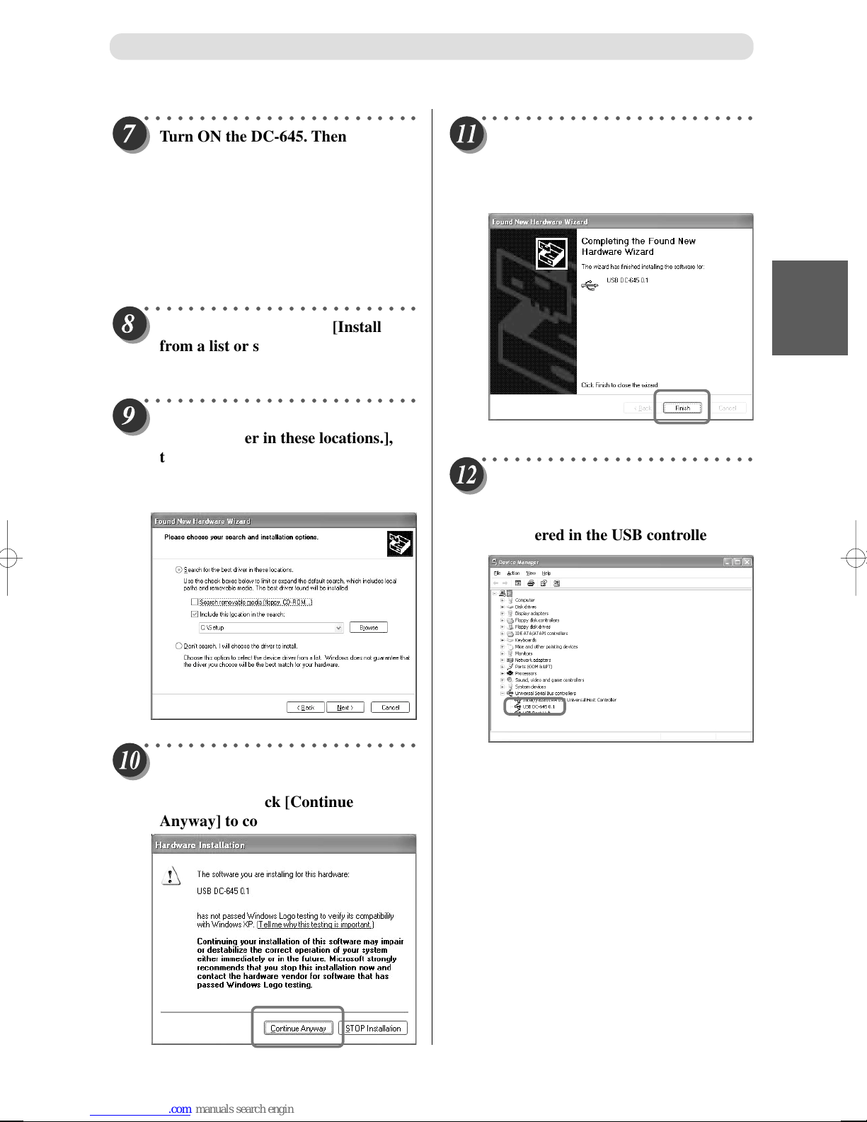
○○○○○○○○○○○○○○○○○○○○○○○○○
Turn ON the DC-645. Then connect
the computer and DC-645 using a
USB cable. (Computer USB Terminal
- DC-645 USB Terminal) (USB cable
(A to B type): The cable length must
be within 3 m.)
“Found New Hardware Wizard” menu appears
on the computer.
○○○○○○○○○○○○○○○○○○○○○○○○○
Click the radio button of [Install
from a list or specific location
(Advanced)], then click [Next].
○○○○○○○○○○○○○○○○○○○○○○○○○
Click the radio button of [Search for
the best driver in these locations.],
then click and select [Search
removable media].
Click [Browse], then click [Next].
○○○○○○○○○○○○○○○○○○○○○○○○○
When installation is completed, the
screen shown below appears. Click
[Finish] to end the Wizard.
○○○○○○○○○○○○○○○○○○○○○○○○○
Installation is successful if the
[Device Manager] dialog indicates
that the [USB DC-645 *.*] is
registered in the USB controller.
1
2
Program JOB for DC-645 Via Computer (JOB Creator)
○○○○○○○○○○○○○○○○○○○○○○○○○
Driver installation starts.
A warning dialog appears during
installation. Click [Continue
Anyway] to continue installation.
This completes the preparation and installing procedures.
31
Page 33
Installing JOB Creator
Installing Procedures (Macintosh)
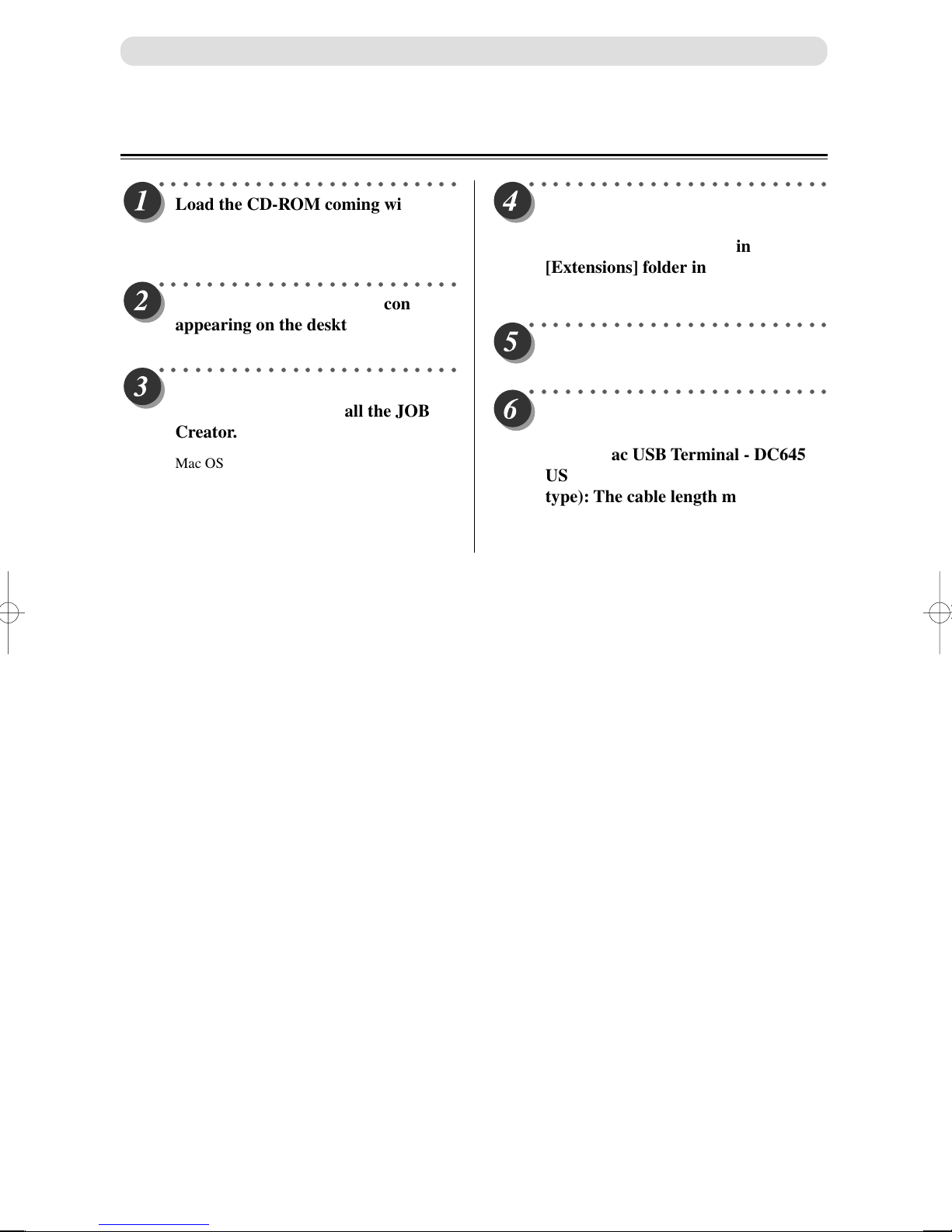
○○○○○○○○○○○○○○○○○○○○○○○○○
Load the CD-ROM coming with this
machine in the CD-ROM drive of
your Macintosh.
○○○○○○○○○○○○○○○○○○○○○○○○○
Double click the CD-ROM icon
appearing on the desktop.
○○○○○○○○○○○○○○○○○○○○○○○○○
Copy [DC-645 JOB Creator] to
where you want to install the JOB
Creator.
Mac OS9 Users → Go to “Step 4”.
Mac OSX Users → Go to “Step 5”.
○○○○○○○○○○○○○○○○○○○○○○○○○
ONLY for Mac OS 9: Copy the
[USBDC645] on the CD-ROM
coming with the package in
[Extensions] folder in the [System]
folder.
○○○○○○○○○○○○○○○○○○○○○○○○○
Restart (reboot) the Macintosh.
○○○○○○○○○○○○○○○○○○○○○○○○○
Turn ON the DC-645. Then connect
the Mac and DC-645 with a USB
cable (Mac USB Terminal - DC645
USB Terminal). (USB cable (A to B
type): The cable length must be
within 3 m.)
This completes the preparation and installing procedures.
32
Page 34
Uninstall and Update JOB Creator
Uninstalling Procedures (Windows)
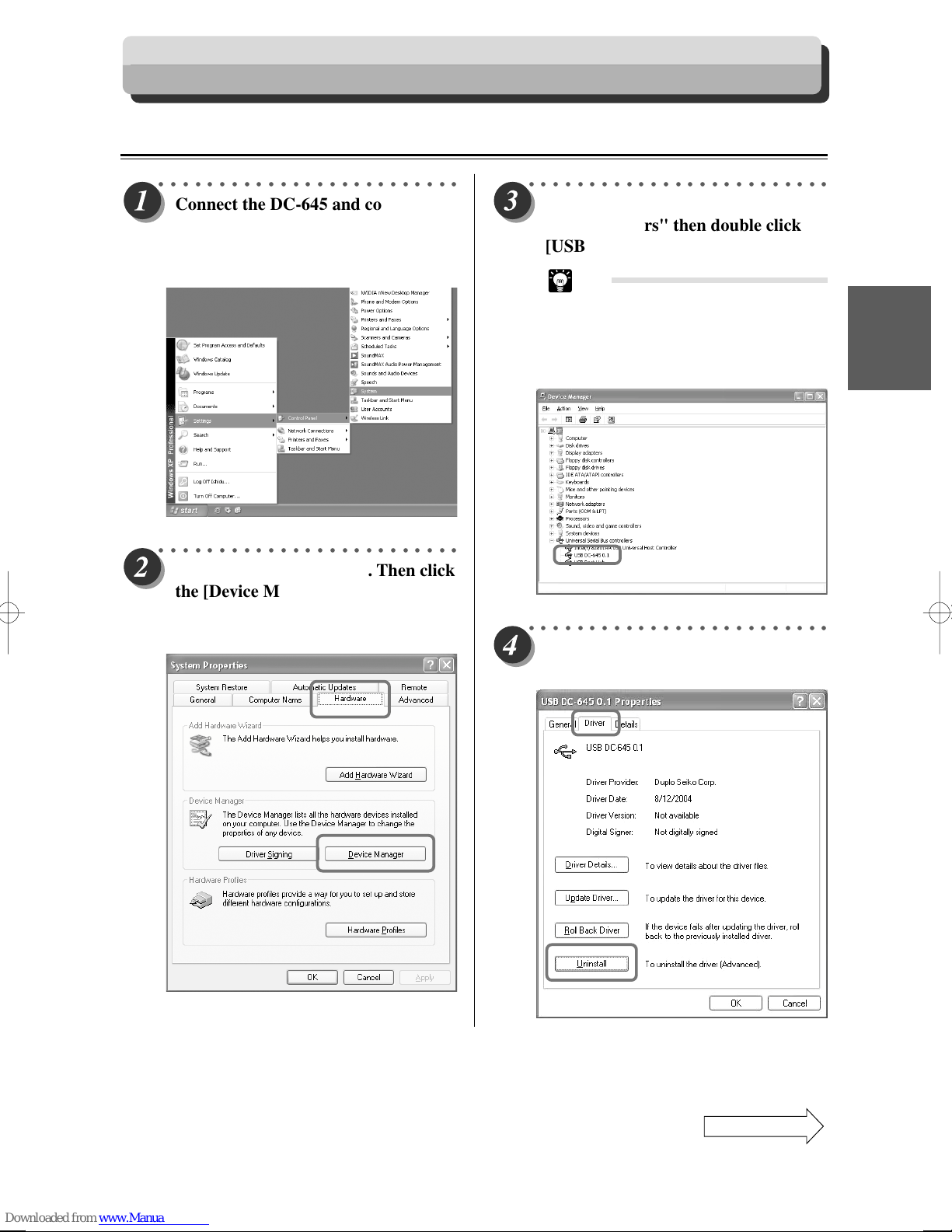
○○○○○○○○○○○○○○○○○○○○○○○○○
Connect the DC-645 and computer.
Select [Start] – [Settings] – [Control
Panel] – [System], then open the
[System Properties] dialog.
○○○○○○○○○○○○○○○○○○○○○○○○○
Select the [Hardware] tab. Then click
the [Device Manager] button.
The [Device Manager] dialog
appears.
○○○○○○○○○○○○○○○○○○○○○○○○○
Go to list and find "Universal Serial
Bus controllers" then double click
[USB DC-645 *.*].
Tip
• Note that the [USB DC-645 *.*] will
not appear in the “Universal Serial
Bus controllers” list unless the DC645 is connected to the computer
with a USB cable.
○○○○○○○○○○○○○○○○○○○○○○○○○
Select the [Driver] tab. Then click the
[Uninstall] button.
1
2
Program JOB for DC-645 Via Computer (JOB Creator)
Continue Page
•••
33
Page 35
Uninstall and Update JOB Creator
○○○○○○○○○○○○○○○○○○○○○○○○○
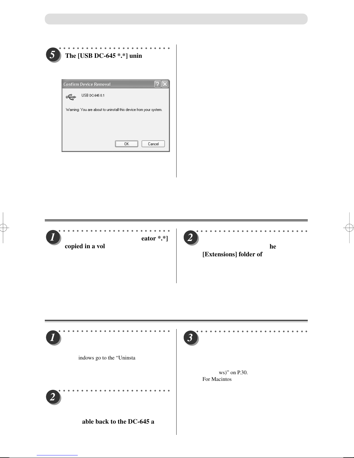
The [USB DC-645 *.*] uninstall
confirmation dialog appears. Click
[Uninstall] then click [OK].
The driver has been successfully removed if [USB DC645 *.*] no longer appears in the list of "Universal Serial
Bus controllers" in the [Device Manager] dialog.
Uninstalling Procedures (Macintosh)
○○○○○○○○○○○○○○○○○○○○○○○○○
Delete the [DC-645 JOB Creator *.*]
copied in a voluntary folder of the
Macintosh.
Mac OS9 Users → Go to “Step 2”.
Mac OSX Users → This completes the driver
removal procedures.
○○○○○○○○○○○○○○○○○○○○○○○○○
ONLY for Mac OS9: Remove the
[USBDC645] copied in the
[Extensions] folder of the [System]
folder on the Macintosh.
This completes the driver removal procedures.
Updating Drivers
○○○○○○○○○○○○○○○○○○○○○○○○○
Uninstall the previous driver using
the driver uninstalling procedures.
For Windows go to the “Uninstalling
Procedures (Windows)” on P.33.
For Macintosh go to the “Uninstalling
Procedures (Macintosh)” above.
○○○○○○○○○○○○○○○○○○○○○○○○○
FOR WINDOWS ONLY: Disconnect
the USB cable connecting the DC-645
and computer. Then reconnect the
USB cable back to the DC-645 and
computer.
○○○○○○○○○○○○○○○○○○○○○○○○○
Install a new driver according to the
Driver Install Procedures on P.31 –
32.
For Windows go to the “Installing Procedures
(Windows)” on P.30.
For Macintosh go to the “Installing Procedures
(Macintosh)” on P.32.
34
Page 36
JOB Creator Settings
Main Menu
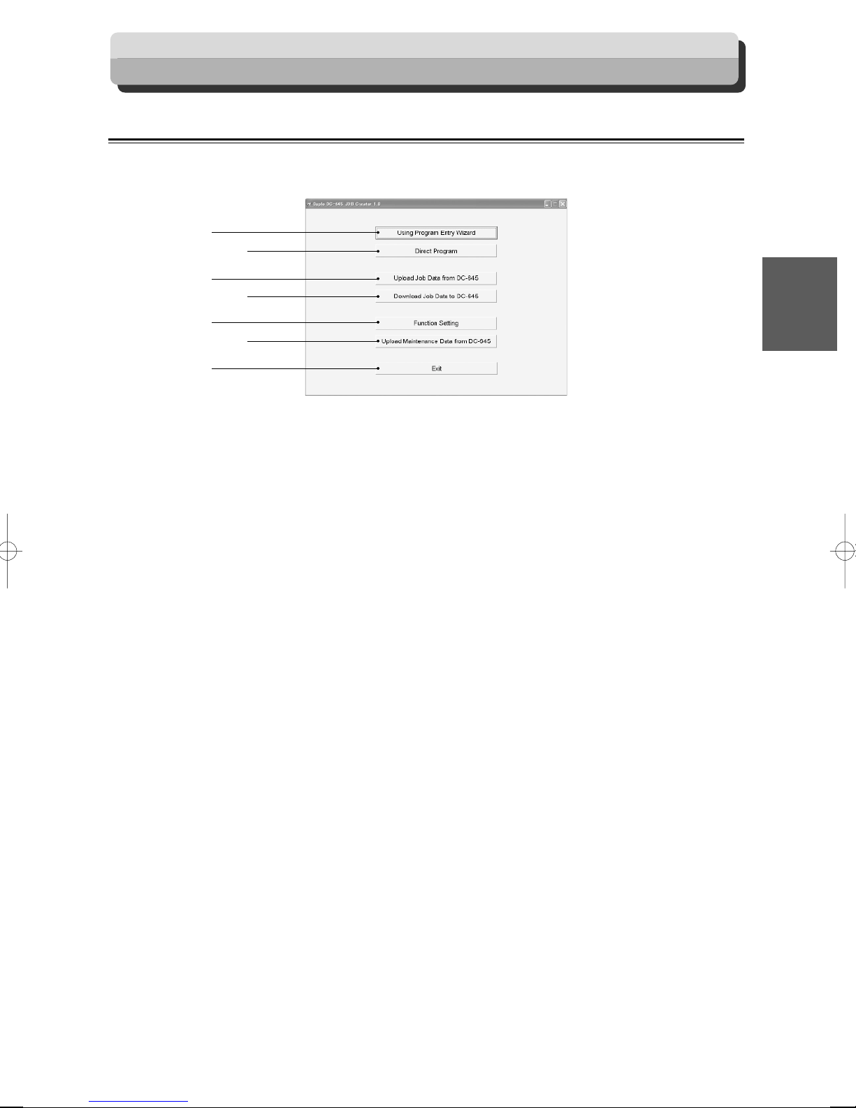
This menu appears when the JOB Creator is launched.
Select the sub menu to set from this main menu, for actual settings.
1
2
3
4
5
6
7
1 Using Program Entry Wizard
Create a JOB in Wizard format.
A preview of the JOB being created is displayed. Create the JOB while checking the input details.
1
2
Program JOB for DC-645 Via Computer (JOB Creator)
2 Direct Program
Directly input the number value to create a JOB.
Use this to create a JOB when the dimensions are already finalized.
3 Upload Job Data from DC-645
Read JOB from DC-645 and save in computer.
4 Download Job Data to DC-645
This sends the JOB saved on the computer to DC-645.
5 Function Setting
This is used to make settings in Function menu.
6 Upload Maintenance Data from DC-645
This creates the file that records the DC-645 status.
This may be used to report the status to the service personnel.
7 Exit
This is used to quit the JOB Creator.
This is the same function as the X button at the top right of the main menu.
35
Page 37

JOB Creator Settings
Creating JOB with Preview Display
This describes the procedures to set up a JOB in Wizard format. Following items should be entered to create a
JOB.
Optional Module ............................ Standard Module
Select an optional module for the job when necessary.
In following JOB, standard module is selected.
JOB Number .................................. 01
Select a JOB No. in which the JOB currently being programmed is saved.
In following JOB, 01 selected.
JOB Name ...................................... DUPLO1
Put a name to the JOB with your keyboard for easy reference.
Following job is named “DUPLO1.”
Paper Size ....................................... 12” x 18” (304.8 mm x 457.2 mm) (Standard Size)
Enter size of the document.
Standard paper size can be selected from “Standard size,” or custom size can be entered in
“Custom size.”
In following JOB, standard 12” x 18” is selected.
REG. Mark .................................... SIDE MARK10 mm (From right edge of document) /
LEAD MARK 10 mm (from top end of document)
Select whether to use REG MARK function or not.
When using this function, enter the position of REG. Mark.
In following JOB the REG. Mark is enabled and the position is 10 mm from the right edge of
document and 10 mm from the lead edge of the document.
(“Using Program Entry Wizard”)
Finished Size .................................. 100mm (W) x 130mm (L)
The size of cards after processing the documents.
Cards per Document ..................... 2 (Crosswise) x 3 (Lengthwise)
Specify how many cards are to be aligned in crosswise and in lengthwise direction.
In following JOB, 2 (crosswise) x 3 (lengthwise) cards are aligned.
Trim ................................................ 23.6 mm (Lead margin), 30 mm (Right margin)
Specify the position of first cut and right margin slit.
In following JOB, first cut is at 23.6 mm from the lead edge, and the right margin slit is at 30 mm
from the right edge of document.
Gutter Slits ..................................... 10mm (Distance between finished documents (left /
right))
When aligning 2 or 3 cards in crosswise direction, it is possible to have a gutter slit between each
cards. Specify the distance between each cards. (The distance should be between 5 mm and 15
mm.)
IN following job, Gutter slits are 10 mm.
36
Page 38

JOB Creator Settings
Gutter Cuts .................................... 10 mm / 10 mm (Distance between finished documents
(top / bottom))
When aligning 2 or more cards in lengthwise direction, it is possible to have a gutter cut between
each cards. The distance should be 4 mm or more.
IN following job, gutter cuts are 10 mm in length.
Crease ............................................. 65 mm
Specify the position of the crease on the cards.
Barcode Reading............................ ON
Auto Cut ......................................... ON
AIR KNIFE .................................... Compressed air is blown out to loosen the document.
This is to prevent double-feed.
FAN REGISTER ........................... Document skewing in feeding area is corrected. When
processing light weight document, turn this function
OFF as it may cause a paper jam in feed area.
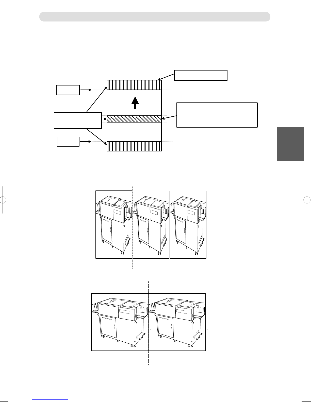
SLIT GUIDE .................................. When any slitters are not used, these slitters act as
paper guide to stabilize the paper conveyance.
Recommended for light weight document.
AUTO CUT .................................... Lead margin, trail margin, and any gutter cuts (shorter
than 85 mm) are finely cut and dropped into the waste
box. When documents do not have lead margins or trail
margin, this must be turned off.
CREASE DEPTH .......................... This sets the depth of the crease when creasing a
document. Set to MAX for heavy paper and MIN for
light paper.
1
2
Program JOB for DC-645 Via Computer (JOB Creator)
SPEED ............................................ This is used to select HIGH / LOW processing speed.
Set to LOW for better processing precision.
Continue Page
•••
37
Page 39
JOB Creator Settings
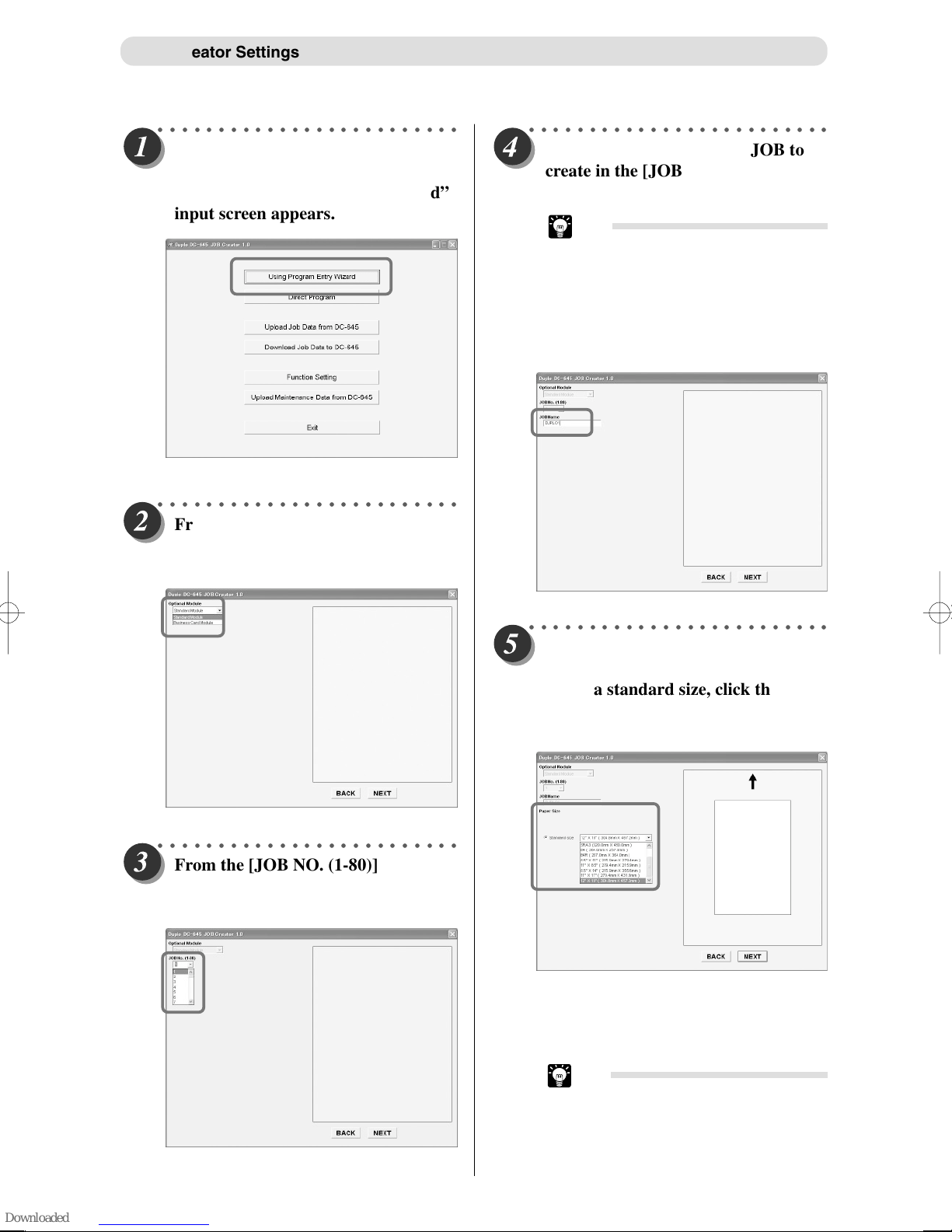
○○○○○○○○○○○○○○○○○○○○○○○○○
Click the [Using Program Entry
Wizard] button.
The “Using Program Entry Wizard”
input screen appears.
○○○○○○○○○○○○○○○○○○○○○○○○○
From the [Optional Module] list,
select the optional module to finish
the JOB then click [NEXT].
○○○○○○○○○○○○○○○○○○○○○○○○○
Input the JOB name of the JOB to
create in the [JOB Name] list, then
click [NEXT].
Tip
• The JOB name can be input with a
maximum of 13 characters.
• Usable Characters
Alphabets: A to Z, a to z
Numbers: 0 to 9
Symbols: ! " # $ % & ' ( ) - @ [ ] ; : ,
. / + * < > ? _ and space.
○○○○○○○○○○○○○○○○○○○○○○○○○
From the [JOB NO. (1-80)] list, select
the JOB Number of the JOB to
create, then click [NEXT].
○○○○○○○○○○○○○○○○○○○○○○○○○
Select the document size before
finishing.
If it is a standard size, click the
[Standard Size] radio button, then
select the size from the list.
If it is a nonstandard size, click the [Custom
Size] radio button, then input the number values
of the [Width] and [Length] on the right.
Click [NEXT] when the numbers are set.
38
Tip
• The range of number values that can
be input is displayed by each input
item of the JOB Creator. Use this as
a guideline (reference) to create a
JOB.
Page 40
JOB Creator Settings
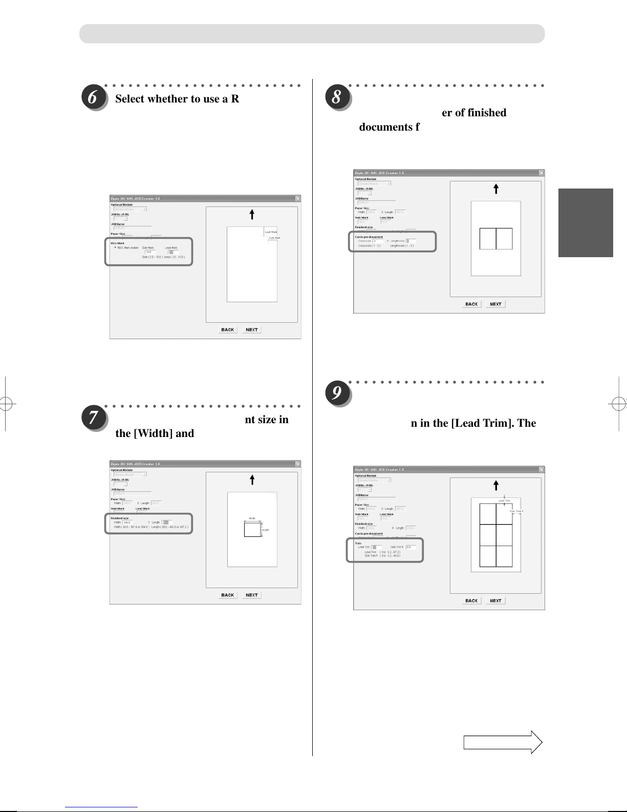
○○○○○○○○○○○○○○○○○○○○○○○○○
Select whether to use a REG. Mark
reading.
When using a REG. Mark, then click
the [REG. Mark enable] radio
button. Then input the number value
for [REG. Mark 1] and [REG. Mark
2] on the right.
When not using a REG. Mark, then click the
[REG. Mark disable] radio button. Click
[NEXT] once it is set.
○○○○○○○○○○○○○○○○○○○○○○○○○
Input the finished document size in
the [Width] and [Length], then click
[NEXT].
○○○○○○○○○○○○○○○○○○○○○○○○○
Respectively input the vertical and
horizontal number of finished
documents for the documents before
they are cut, in the [Crosswise] and
[Lengthwise] area.
Set [Crosswise] then click [NEXT] and go to
[Lengthwise]. Set [Lengthwise] then click
[NEXT] again to go to the next setting.
○○○○○○○○○○○○○○○○○○○○○○○○○
Set the margin of the document.
Input the number value of the topside margin in the [Lead Trim]. Then
input the number value of the rightside margin in the [Side Trim R].
1
2
Program JOB for DC-645 Via Computer (JOB Creator)
Set [Lead Trim] then click [NEXT] and go to
[Side Trim R]. Set [Side Trim R] then click
[NEXT] again to go to the next setting.
Continue Page
•••
39
Page 41
JOB Creator Settings
○○○○○○○○○○○○○○○○○○○○○○○○○
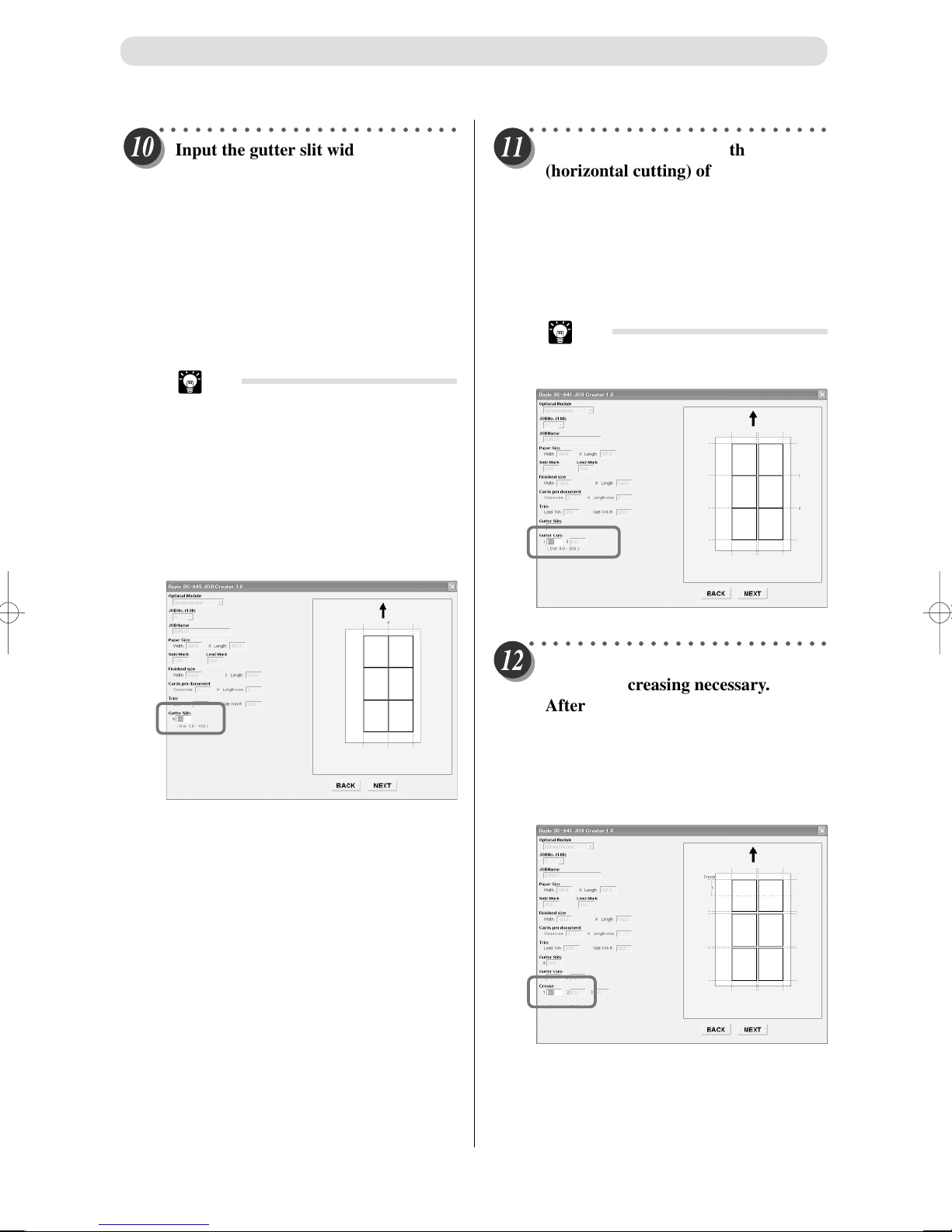
Input the gutter slit width (width
between each cards) (vertical cutting)
of the size determined document.
Input 0 if there is no gutter between
cards.
After inputting one number value,
click [NEXT]. Then input the next
number value. Set the all gutter slit
widths.
When all settings are complete, click [NEXT].
Tip
• If in Step 8, Crosswise = 1, then the
gutter slit width cannot be input.
• Only one gutter slit can be set if
crosswise is set to 3.
• No gutter slit can be set if crosswise
is set to 5 or more.
• The gutter slit cannot be changed if
the “Business Card Module” is
selected for the Optional Module.
(Fixed value: 5 mm)
○○○○○○○○○○○○○○○○○○○○○○○○○
Input the gutter cut length
(horizontal cutting) of the size
determined document.
Input 0 if there is no distancing.
After inputting one number value,
click [NEXT]. Then input the next
number value. Set the all gutter cut
lengths.
Tip
• If in Step 8, Lengthwise = 1, then the
gutter cut length cannot be input.
○○○○○○○○○○○○○○○○○○○○○○○○○
Input the creasing position. Input 0 if
there is no creasing necessary.
After inputting one number value,
click [NEXT]. Then input the next
number value. Set the distance of all
creasing positions.
When all settings are complete, click [NEXT].
40
Page 42

JOB Creator Settings
○○○○○○○○○○○○○○○○○○○○○○○○○
Set functions for this job by clicking
the [FUNCTION] button, then open
the “Function Settings” dialog.
When the settings are completed,
click [OK] and close the dialog. Then
click [NEXT].
○○○○○○○○○○○○○○○○○○○○○○○○○
The details of all the settings will
appear in a list. Check to see if the
JOB details are correct. If there are
any numbers to modify, re-input the
values at this time.
Tip
• For the “Function Settings” click the
[Function] button, open the “Function
Settings” dialog, then Confirm/
Modify.
Tip
• When the “Business Card Module” is
selected, it is possible to adjust the
business card processing position
with “Option 1” of this display item.
○○○○○○○○○○○○○○○○○○○○○○○○○
To register the JOB created with the
DC-645 immediately, click the
[DOWNLOAD] button.
Tip
• To save the JOB created on the
computer as a file, click [SAVE].
Determine the file name and where to save the
file. Then click [OK] to save the file.
The JOB file created can be registered on the
DC-645 again with “Download Job Data to DC645” of the main menu.
(a P.47 to “JOB Saved on computer Registered
on DC-645 [Download Job Data to DC-645]”)
1
2
Program JOB for DC-645 Via Computer (JOB Creator)
Tip
• When inputting the settings from
your computer, the machine
automatically judges positions of
slitters and the positions sometimes
differs from the description on page
19.
Tip
• The [Optional Module] cannot be
modified.
Continue Page
•••
41
Page 43

JOB Creator Settings
○○○○○○○○○○○○○○○○○○○○○○○○○
A registration confirmation dialog
appears. Click [YES].
Tip
• When downloading JOB data to the
DC-645, the JOB data is generally
registered in the DC-645 memory. To
update the JOB data without
registering it in memory, check the
“Temporary job data” check box at
the bottom of this dialog.
The JOB data downloaded as
“Temporary job data” will be deleted
when the DC-645 is turned OFF or
when another JOB is selected. To
download (save) the JOB data,
always download the “Job data”
without “Temporary job data” check
marked, or save the JOB data on the
computer with the JOB Creator
before downloading it.
Tip
• If there is already a JOB registered
in selected job number in the DC645 memory, a display appears
whether to overwrite file or not.
○○○○○○○○○○○○○○○○○○○○○○○○○
Click [OK] and a display indicating
that the data was successfully sent,
appears in approximately one second.
○○○○○○○○○○○○○○○○○○○○○○○○○
The dialog appears to ask whether to
test the program.
To test the created job by running 1
document, set the document on the
DC-645 then click [TEST]. If a test is
not intended, then click [NO].
42
ThiscompletestheJOBcreationprocedures.
Page 44

JOB Creator Settings
Creating a JOB By Direct Number Input (“Direct Program”)
With Direction program, the JOB is created by directly inputting the number value of each item, in the same
manner as the JOB program of the DC-645 main unit.
This describes the procedures to create a JOB with Direct Program.
○○○○○○○○○○○○○○○○○○○○○○○○○
Click the [Direct Program] button.
The Direct Program input menu
appears.
○○○○○○○○○○○○○○○○○○○○○○○○○
Input the JOB number of the JOB to
create in the [JOB No. (1-80)] list.
○○○○○○○○○○○○○○○○○○○○○○○○○
Input the JOB name of the JOB to
create in the [JOB Name] list.
Tip
• The JOB name can be input with a
maximum of 13 characters.
• Usable Characters
Alphabets: A to Z, a to z
Numbers: 0 to 9
Symbols: ! " # $ % & ' ( ) - @ [ ] ; : ,
. / + * < > ? _ and space.
1
2
Program JOB for DC-645 Via Computer (JOB Creator)
○○○○○○○○○○○○○○○○○○○○○○○○○
From the [Optional Module] list,
select the optional module to finish
the JOB.
Continue Page
•••
43
Page 45

JOB Creator Settings
○○○○○○○○○○○○○○○○○○○○○○○○○
Input the number value of each item
to create a JOB according to the
details intended.
Tip
• Slitter values cannot be changed if
the “Business Card Module” is
selected for the Optional Module.
Tip
• Option value cannot be set if the
“Standard Module” is selected for the
Optional Module.
○○○○○○○○○○○○○○○○○○○○○○○○○
Set the functions for this JOB by
clicking the [FUNCTION] button,
then open the “Function Settings”
dialog.
When the settings are completed,
click [OK] and close the dialog.
This completes the JOB programming procedures.
JOB registration and save can be done with the same
procedures as the Wizard system.
Run according to Steps 15 – 18 on page 41.
44
Page 46

JOB Creator Settings
Reading JOB from DC-645 (“Upload Job Data from DC-645”)
This describes the procedures to read a JOB from the DC-645 memory to the JOB Creator.
○○○○○○○○○○○○○○○○○○○○○○○○○
Click the [Upload Job Data from DC645] button.
The display to select the JOB to read
appears.
○○○○○○○○○○○○○○○○○○○○○○○○○
(To upload all JOB (#1 – #80) from
the DC-645 memory)
Click the [ALL JOB] radio button,
then click the [UPLOAD] button.
Tip
• With the above operations, JOB No.
1 – 80 is saved as 1 file.
(To select and upload only one JOB)
Click the [JOB No.] radio button.
Then select the JOB number to
upload from the following list.
1
2
Program JOB for DC-645 Via Computer (JOB Creator)
After selecting the JOB number, click the
[UPLOAD] button.
Continue Page
•••
45
Page 47

JOB Creator Settings
○○○○○○○○○○○○○○○○○○○○○○○○○
A display confirming whether to start
uploading the JOB will appear. Click
the [YES] button.
○○○○○○○○○○○○○○○○○○○○○○○○○
(To read all JOB from the DC-645
memory)
A JOB successfully read display will
appear. Click the [SAVE] button to
save the JOB on the computer or
click [END] to quit uploading the
JOB.
(When selecting and uploading only
ONE JOB)
The details of the JOB will appear in
a list.
If there are any number values to edit, input the
changes at this time.
To register the JOB edited with DC-645, click
the [DOWNLOAD] button.
To save the edited JOB on the computer, click
[SAVE]. Then, designate the file name and
place to save the file and then click [OK] to
save.
Click [BACK] to read the JOB data once again.
Tip
• The [Optional Module] cannot be
modified.
Tip
• Slitter values cannot be changed if
the “Business Card Module” is
selected for the Optional Module.
Tip
• Option value cannot be set if the
“Standard Module” is selected for the
Optional Module.
If [END] is clicked, then a display will appear
confirming whether to quit reading the JOB.
Click [YES].
46
Page 48
JOB Creator Settings
JOB Saved on Computer Registered On DC-645 (“Download Job Data to DC-645”)
This section describes the procedures to register on the DC-645 a JOB saved on the computer.
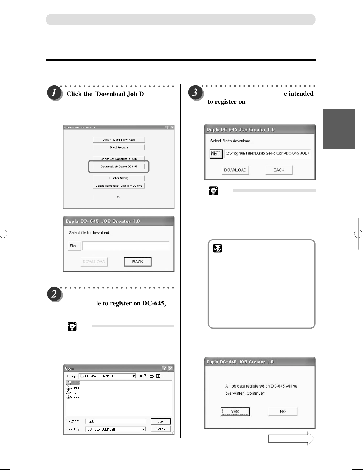
○○○○○○○○○○○○○○○○○○○○○○○○○
Click the [Download Job Data to DC645] button.
A display appears to select a JOB file
to send to the DC-645.
○○○○○○○○○○○○○○○○○○○○○○○○○
Click the [File...] button. Select and
click the file to register on DC-645,
then click the [Open] button.
Tip
• Extension of a file saved with ONE
JOB data: .djob
Extension of a file saved with ALL
JOB data: .dall
○○○○○○○○○○○○○○○○○○○○○○○○○
Check whether the JOB file intended
to register on the DC-645 is selected.
Then click the [DOWNLOAD]
button.
Tip
• When sending ONE JOB (with .djob
extension), if that JOB number
already exists in the DC-645
memory, then a display will appear
whether to overwrite the existing
JOB with this JOB.
IMPORTANT
• If the document file has a
extension, then the maximum
JOBs that can be registered on
the DC-645 are all saved.
When registering a file with a
“.dall”
extension on the DC-645,
all JOBs registered on the DC-645
at that time will be overwritten.
A display will appear to check
whether to overwrite all JOBs
when sending the data.
Confirm whether it is okay to overwrite the data
and if so click the [YES] button and send the
data.
“.dall”
1
2
Program JOB for DC-645 Via Computer (JOB Creator)
Continue Page
•••
47
Page 49
JOB Creator Settings
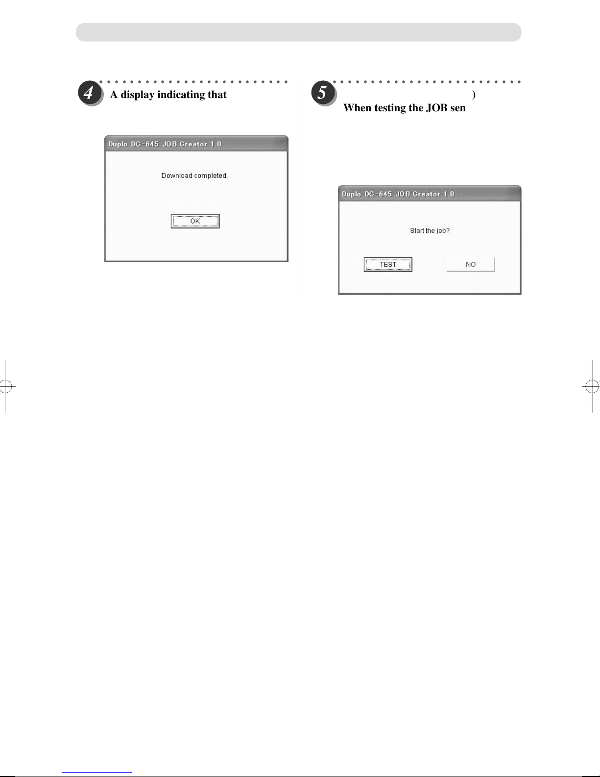
○○○○○○○○○○○○○○○○○○○○○○○○○
A display indicating that the JOB
was successfully transmitted appears.
Click the [OK] button to quit.
○○○○○○○○○○○○○○○○○○○○○○○○○
(To register only ONE JOB)
When testing the JOB sent
(processing one), a confirmation
screen will appear. To run the test, set
the document on the DC-645 then
click [TEST]. If a test is not intended,
then click [NO].
48
Page 50
JOB Creator Settings
Setting Frequent Functions From Computer (“Function Setting”)
This describes the procedures to turn ON/OFF the barcode function, REG. Mark function and other functions.
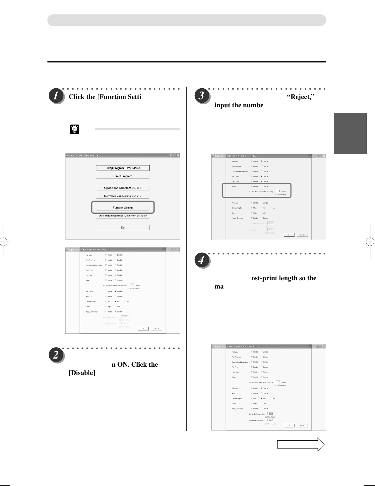
○○○○○○○○○○○○○○○○○○○○○○○○○
Click the [Function Setting] button.
The display to turn ON/OFF the
function appears.
Tip
• The current DC-645 settings will
appear at this time.
○○○○○○○○○○○○○○○○○○○○○○○○○
Click the [Enable] radio button for
function to turn ON. Click the
[Disable] radio button for functions
to turn OFF.
○○○○○○○○○○○○○○○○○○○○○○○○○
If you set to [Enable] on “Reject,”
input the number of rejected
documents to stop the JOB.
Input “0” or click the [Disable] radio
button if DC-645 is not to be stopped
regardless of number of rejected
documents.
○○○○○○○○○○○○○○○○○○○○○○○○○
If you set to [Enable] on “Apply
Shrinkage,” input the pri-print
length and post-print length so the
machine can automatically calculate
the shrinkage rate and improve the
JOB processing precision.
Use the <Number> key to first input
the document length before printing.
Next, input the length of the
document after printing.
1
2
Program JOB for DC-645 Via Computer (JOB Creator)
Continue Page
•••
49
Page 51
JOB Creator Settings
○○○○○○○○○○○○○○○○○○○○○○○○○
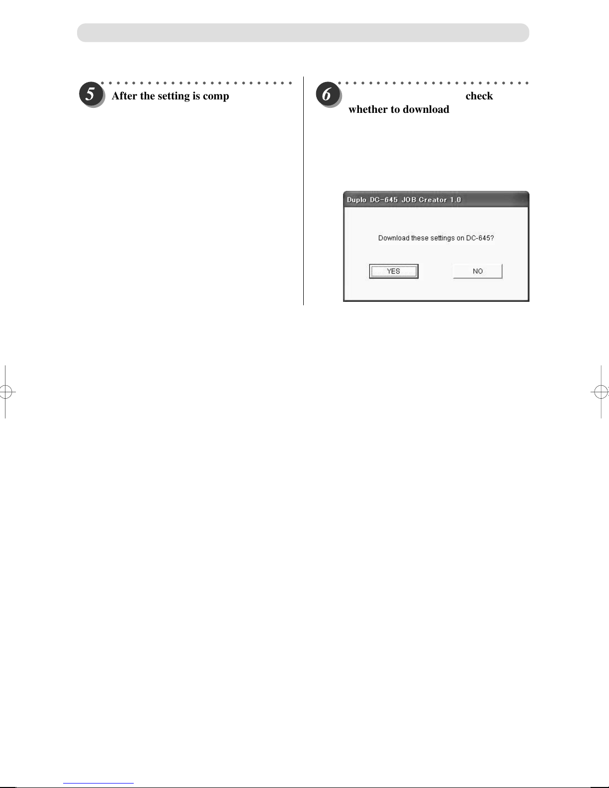
After the setting is completed, click
the [OK] button.
○○○○○○○○○○○○○○○○○○○○○○○○○
A display will appear to check
whether to download the Function
Setting Displayed contents on the
DC-645.
If it is okay, then click [OK].
If it is not okay, then click [NO]. The screen
will return to the [Function Setting] display.
50
Page 52
JOB Creator Settings
Create a File Recording the DC-645 Maintenance Information
(“Upload Maintenance Data from DC-645”)
This describes the procedures to create a file recording the DC-645 Maintenance Information.
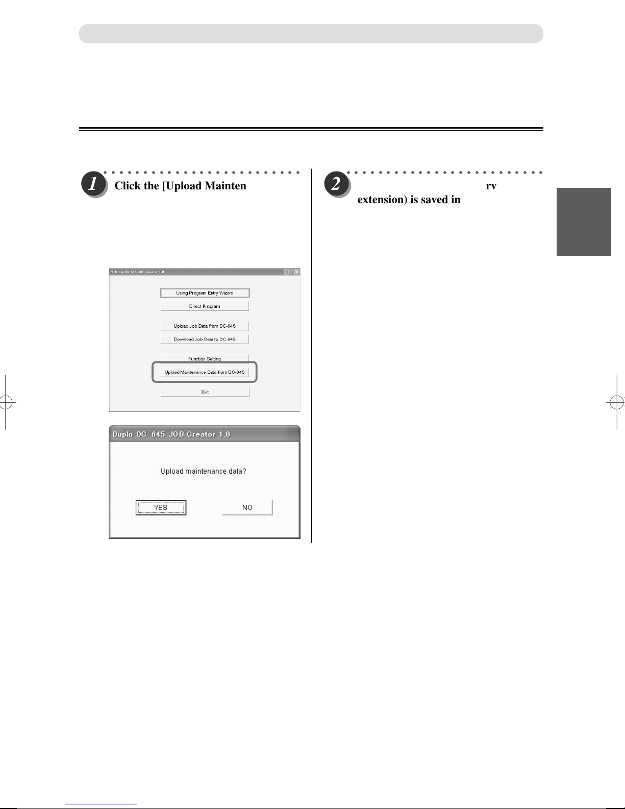
○○○○○○○○○○○○○○○○○○○○○○○○○
Click the [Upload Maintenance Data
from DC-645] button.
A display appears to confirm
whether to start reading the DC-645
Maintenance Information.
Click the [YES] button.
○○○○○○○○○○○○○○○○○○○○○○○○○
The Maintenance File (.dsrv
extension) is saved in the same
direction as the DC-645 application
software.
1
2
Program JOB for DC-645 Via Computer (JOB Creator)
51
Page 53

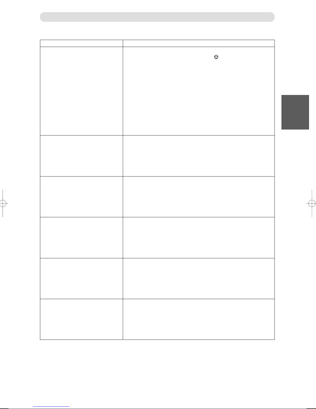
List of Messages
Message
Cannot enter Gutter Slits.
Cannot enter Gutter Cuts.
The above job name is invalid.
Communication Error (001) – (***)
Countermeasure
Cannot input gutter slit since the number of page layout in the horizontal-
direction is either 1 or more than 4.
Cannot input gutter cut since the number of page layout in the vertical-
direction is 1.
The JOB name contains a character that cannot be used.
The JOB Creator cannot recognize the DC-645.
Check the following.
1. Is the USB cable securely connecting the computer and DC-645?
(a P.18 “How to Connect the DC-645 to your Computer”)
2. Is the DC-645 turned ON?
3. (Macintosh OS9): Is the USB driver copied in the [Extensions] folder in
the [System] folder? Check to see if its use has been turned OFF?
(a P.32 “Installing Procedures” (Macintosh)].
4. (Macintosh OSX): Is a Classic environment launched?
5. (Windows): Is [USB DC-645 Ver*.*] registered as a USB controller in
the [Device Manager] dialog?
(a P.30 “Installing Procedures (Windows)”)
6. Is the USB cable shorter than 3 meters?
Communication Error (002) – (003)
Communication Error (004)
File I/O ERROR
Communication Error occurred.
1. Restart the DC-645 and computer.
2. Is the USB cable shorter than 3 meters?
Communication error occurred with DC-645 while the DC-645 and the
computer was communication, showing a “Busy / Error / Jam Warming”.
Check the LCD panel for the Error display. Correct the Error, JAM and/or
Warning according to the procedures described in “Error Display” (P.80),
“Warming Display” (P.82), and “When a Paper Jam Has Occurred” (P.83 –
99).
Retry communications after that.
(Windows) Illegal file path. Check the correct file path.
52
Page 54
Message Countermeasure
DC-645 is busy.
ERROR on DC-645
List of Message
The DC-645 is in operation.
1. Either wait for the JOB to quit or press the <STOP> key on the DC-
645 to abort the JOB.
2. DC-645 is not ready to operate.
End the function setting, input, and JOB select mode, and go to the
Operation Mode (regular state).
3. An error has occurred with the DC-645.
Check the message displayed on the LCD panel and correct the error
according to the Troubleshooting Instructions described in this
Instruction Manual.
(a P.78 “OK Monitor Display and Jam Display”)
(a P.80 “Error Display”)
(a P.82 “Warning Display”)
Error is detected on DC-645.
Check the LCD panel for the Error display. Correct the Error, JAM and/or
Warning according to the procedures described in “Error Display” (P.80),
“Warming Display” (P.82), and “When a Paper Jam Has Occurred” (P.83 –
99).
1
2
Program JOB for DC-645 Via Computer (JOB Creator)
Load Paper
Install the Slitter Module.
Install the Standard Module.
Install the Business Card Module.
There is no document set in the 645 feed tray.
Install the Slitter Module on DC-645.
Install the Standard Module on DC-645.
Install the Business Card Module on DC-645.
Iftheproblemisnotsolvedwiththeaboveremedies,contacttheservicepersonnel.
53
Page 55
Chapter 3
Programing JOB for DC-645 on Control Panel
DC-645 can save 80 patterns of JOBs. Job contents can be programmed either via computer or on the
control panel. This chapter describes how to program a JOB on control panel of DC-645. Following items
should be entered to program a JOB.
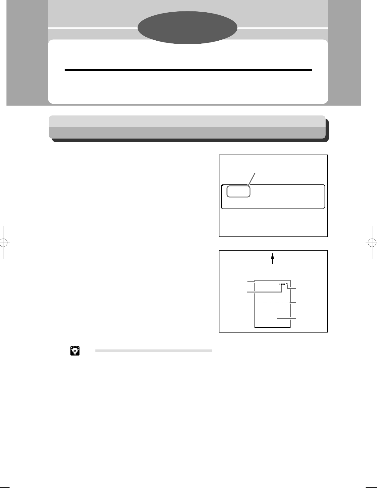
Prior to Programming a Job
Before programming a job carefully measure, in
mm, the required slits, cuts and creases. See the
Figure 1 for reference and Figure 2 for a
detailed description of each function.
Familiarize yourself with the following illustrations and instructions to make the programming process easy and trouble free.
IMPORTANT NOTE
There are a total of six slitters. Two slitters are
for the margins and the remaining four slitters
are for the center of the document.
There is a guillotine cutter that performs cuts
perpendicular to the paper feeding direction.
DC-645 can cut up to 15 cuts on 1 document.
There is a creaser that performs creases
perpendicular to the paper feeding direction.
DC-645 can crease up to 10 creasing on 1
document.
Program
Number
01? (01––80
OK?––>SET
Figure 1
PAPER FEEDING DIRECTION
Cut
Barcode
(Optional)
Figure 2
)
REG. Mark
(Optional)
Crease
Slit
Tip
• Record the contents of each job in “Customer
Programmed Jobs” list for your easy reference.
54
Page 56
Definition of Programming Terms
AUTO CUT
Paper area before first cut and after last cut, and area between 2 cuts which is 20 – 84.99 mm long, are considered to be
waste and will be chopped up for disposal in waste box when AUTO CUT is enabled.
Leading edge of the paper
First Cut
When the distance between two cuts
arre 20 – 84.99 mm long, they will be
Area where automatic
cutting can be done
Last Cut
When documents do not have lead or trail margin, (as in the example 1 and 2 below), make certain to turn OFF the
AUTO CUT feature.
chopped up for smooth disposal into the
waste box.
1
3
Programing JOB for DC-645 on Control Panel
Example 1 - When AUTO CUT must be OFF
Example 2 - When AUTO CUT must be OFF
55
Page 57

Customer Programmed Jobs
ALL DIMENSIONS MUST BE IN MILLIMETERS
JOB Name
JOB No.
TOTAL LENGTH
PAPER WIDTH
OPTION
Side Mark
Lead Mark
SLIT1
SLIT2
SLIT3
SLIT4
SLIT5
SLIT6
CUT1
CUT2*
CUT3*
CUT4*
CUT5*
CUT6*
CUT7*
CUT8*
CUT9*
CUT10*
CUT11*
CUT12*
CUT13*
CUT14*
CUT15*
CRE.01*
CRE.02*
CRE.03*
CRE.04*
CRE.05*
CRE.06*
CRE.07*
CRE.08*
CRE.09*
CRE.10*
OPTION1
OPTION2
AIR KNIFE
FAN REG.
REG. MARK
SLIT GUIDE
AUTO CUT
CREASE DEPTH
SPEED
THERE IS A MAXIMUM OF 15 CUTS AND 10 CREASES
CONVERSION TABLE
Inches Millimeters
1.0 225.4
8.5 215.9
CONVERSION TABLE
Inches Millimeters
11 279.4
17 431.8
56
Page 58

How to Program Job on Control Panel
Optional module ............................ Select an optional module for the job when necessary.
JOB number................................... Select a JOB no. in which the JOB currently being
programmed is saved.
JOB name ....................................... Put a name to the JOB with number keys for easy
reference.
Paper length ................................... length of document
Paper width .................................... width of document
REG MARK position .................... When using REG. mark reading:
The distance between lead edge and leadmark, and the
distance between right edge and side mark.
Slit positions ................................... Distances between right edge and each slit position.
DC-645 can slit up to 6 positions on 1 document.
Cut positions .................................. Distances between lead edge and each cut positions.
DC-645 can cut up to 15 positions on 1 document.
Crease position............................... Distances between lead edge and each crease positions.
DC-645 can crease up to 10 creases on 1 document.
Option positions ............................. Distances between right edge and each option positions.
AIR KNIFE .................................... Compressed air is blown out to loosen the document.
This is to prevent double-feed.
FAN REGISTER ........................... Document skewing in feeding area is corrected. When
processing light weight document, turn this function
OFF as it may cause a paper jam in feed area.
1
3
Programing JOB for DC-645 on Control Panel
SLIT GUIDE .................................. When any slitters are not used, these slitters act as
AUTO CUT .................................... Lead margin, trail margin, and any gutter cuts (shorter
CREASE DEPTH .......................... This sets the depth of the crease when creasing a
SPEED ............................................ This is used to select HIGH/LOW processing speed.
paper guide to stabilize the paper conveyance.
Recommended for light weight document.
than 85mm) are finely cut and dropped into the waste
box. When documents do not have lead margins or trail
margin, this must be turned off.
document. Set to MAX for heavy paper and MIN for
light paper.
57
Page 59

How to Program Job on Control Panel
○○○○○○○○○○○○○○○○○○○○○○○○○○○○○○○○○○○○○○○○○○○○○○○○○○○○○○○○○
Turn on the machine.
○○○○○○○○○○○○○○○○○○○○○○○○○○○○○○○○
Repeatedly push the <MODE> key until the
LCD panel indicates [INPUT].
[INPUT
]
INPUT––>SET
○○○○○○○○○○○○○○○○○○○○○○○○○○○○○○○○
Press and hold the <SET> key until the LCD
panel appears as shown on the right with a
beep.
○○○○○○○○○○○○○○○○○○○○○○○○○○○○○○○
Use the <Number> key pad to enter the job
number.
01? (01––80
OK?––>SET
52? (01––80
)
)
Press the <SET> key when input is completed.
○○○○○○○○○○○○○○○○○○○○○○○○○○○○○○○○
OK?––>SET
Select the optional module for this JOB with the
<+> key or <–> key.
Pressthe <SET> keywheninputiscompleted.
○○○○○○○○○○○○○○○○○○○○○○○○○○○○○○○○○○○○○○○○○○○○○○○○○○○○○○○○○
OP MODULE (+,–
STANDARD
)
Use the <Number> key pad to enter the JOB name.
Maximum 13 letters can be entered.
Press the <SET> key when input is completed.
11→ ! → ” → # → $ → % → & → ’ → ( → ) → 1
2A→ B → C → a → b → c → 2 → A
3D→ E → F → d → e → f → 3 → D
4G→ H → I → g → h → i → 4 → G
5J→ K → L → j → k → l → 5 → J
6M→ N → O → m → n → o → 6 → M
7P→ Q → R → S → p → q → r → s → 7 → P
8T→ U → V → t → u → v → 8 → T
9W→ X → Y → Z → w → x → y → z → 9 → W
00→ * → + → , → - → . → / → : → ; → < → > → ? → @ → 0
C Clear
JOG Space, Move the cursor to the right
JOG Space, Move the cursor to the left
58
Page 60

How to Program Job on Control Panel
Example:
1. Press the < 3 > key and <JOG> key.
2. Press the < 8 > key 2 times and <JOG> key.
3. Press the < 7 > key and <JOG> key.
4. Press the < 5 > key 3 times and <JOG> key.
5. Press the < 6 > key 3 times and <JOG> key.
6. Press the <SET> key.
○○○○○○○○○○○○○○○○○○○○○○○○○○○○○○○○
Enter the total length (in mm) of the document.
Pressthe <SET> keywheninputiscompleted.
Tip
• WhenprogrammingaJOB(INPUTmode),press
the<JOG>keytomovetoNEXTorPrevious
display.
<JOG> key: Go to the next display
<JOG> key: Go to the previous display
Tip
• When programming a JOB (INPUT mode), press
the <STOP> key to quit the JOB program and
return to the regular LCD display.
52:DUPLO
12345
TOTAL LENGTH ?
(
210–650)460.0mm
PREPRINTED
SAMPLE
1
3
Programing JOB for DC-645 on Control Panel
○○○○○○○○○○○○○○○○○○○○○○○○○○○○○○○○
Enter the paper width (in mm) of the document.
Pressthe <SET> keywheninputiscompleted.
○○○○○○○○○○○○○○○○○○○○○○○○○○○○○○○○
Measure the distance (in mm) between the
Right edge of the paper and the vertical portion
of the Side mark. Input the distance of Side
mark by <Number> key.
The value must be between 3 and 15 mm when
REG. Mark is not used enter 0.0 mm.
PAPER WIDTH ?
(
210–370)297.0mm
10mm
SIDE MARK 10.0mm
(
0,3–15
)
Continue Page
•••
59
Page 61

How to Program Job on Control Panel
○○○○○○○○○○○○○○○○○○○○○○○○○○○○○○○○
Measure the distance (in mm) between the
leading edge of the paper and the horizontal
portion of the REG. Mark. The value must be
between 3 and 15 mim.
○○○○○○○○○○○○○○○○○○○○○○○○○○○○○○○○
Enter the value from step 9 using the
<Number> key. When REG. Mark is not used,
enter 0.
Pressthe <SET> keywheninputiscompleted.
○○○○○○○○○○○○○○○○○○○○○○○○○○○○○○○○
Enter the distance from the right edge of the
document to the position for SLIT1. This value
must be between 0 and 40 mm.
Pressthe <SET> keywheninputiscompleted.
Tip
• When selecting “Business card module” for
optional module, slit positions do not need entry.
Go to step 18.
Tip
• The document will be ejected if the slit position
exceeds the 40 mm upper cutting limit by the
margin slitter due to “REG. mark print position
drift” or “Side mark entry error”.
10mm
LEAD MARK 10.0mm
(
0,3–15
)
SLIT 1 10.0mm
(
0– 40.0
)
○○○○○○○○○○○○○○○○○○○○○○○○○○○○○○○○
Enter the distance from the right edge of the
document to the position for the SLIT 2.
This value must be between 257 and 297 mm.
Pressthe <SET> keywheninputiscompleted.
○○○○○○○○○○○○○○○○○○○○○○○○○○○○○○○○
Enter the distance from the right edge of the
document to the position for the SLIT 3.
This value must be between 58 and 212 mm.
Pressthe <SET> keywheninputiscompleted.
60
SLIT 2 260.0mm
(
0,257.0–297.0
)
SLIT 3 110.0mm
(
0,58.0–212.0
)
Page 62

How to Program Job on Control Panel
○○○○○○○○○○○○○○○○○○○○○○○○○○○○○○○○
Enter the distance from the right edge of the
document to the position for the SLIT 4.
The value must be (the value entered for SLIT 3
+ 48 mm) or more.
Pressthe <SET> keywheninputiscompleted.
○○○○○○○○○○○○○○○○○○○○○○○○○○○○○○○○
Enter the distance from the right edge of the
document to the position for the SLIT 5.
This value must be between 58 and 212 mm.
Pressthe <SET> keywheninputiscompleted.
○○○○○○○○○○○○○○○○○○○○○○○○○○○○○○○○
Enter the distance from the right edge of the
document to the position for the SLIT 6.
The value must be (the value entered for SLIT 5
+ 48 mm) or more.
SLIT 4 160.0mm
(
0,158.0–212.0
)
SLIT 5 60.0mm
(
0,58.0–212.0
)
SLIT 6 210.0mm
(
0,108.0–212.0
)
1
3
Programing JOB for DC-645 on Control Panel
Pressthe <SET>keywheninputiscompleted.
○○○○○○○○○○○○○○○○○○○○○○○○○○○○○○○○
Enter the distance from the leading edge of the
document to the position for CUT 1.
This value must be smaller than the value set
for paper length.
Pressthe <SET>keywheninputiscompleted.
○○○○○○○○○○○○○○○○○○○○○○○○○○○○○○○○
Enter the distance from the leading edge of the
document to the position for CUT 2. This value
must be bigger than the value set for CUT 1 and
smaller than the value set for paper length.
If CUT 2 is not required, enter 0. When there is
only 1 cut on document, AUTO CUT function
must be turned off.
Press the <SET>key when input is completed.
Hereafter, check the number value input, to similarly set to
CUT 15.
CUT01 10.0mm
(
0–460.0
)
CUT02 190.0mm
(
0,95.0–460.0
)
Continue Page
•••
61
Page 63

How to Program Job on Control Panel
○○○○○○○○○○○○○○○○○○○○○○○○○○○○○○○○
Enter the distance from the leading edge of the
document to position for the first crease.
A number value within the length of the paper
length set can be input.
Pressthe <SET>keywheninputiscompleted.
Hereafter,checkthenumbervalueinput,tosimilarlysetto
CRE10.
○○○○○○○○○○○○○○○○○○○○○○○○○○○○○○○○
(The display on the right will only appear when
the Optional Module in Step 8 is set to
“BUSINESS” (Business Card Module)).
Input the distance of the optional module
processing position from the right edge of the
document to the processing position.
Press the <SET>key when input is completed.
○○○○○○○○○○○○○○○○○○○○○○○○○○○○○○○○
Use the <+> key and <–> key to switch between
and turn ON/OFF the compressed air blowout
at the feed area to loosen the documents.
Press the <SET>key when the setting is set.
CRE.01 100.0mm
(
0–460.0
)
OPTION1 5.0mm
(
4.0–10.0
)
AIR KNIFE ON
OFF
∗
Tip
• Turnonthisfunctionwhenprocessing
documentswithexcessivestaticelectricityor
heavyweightdocuments.
○○○○○○○○○○○○○○○○○○○○○○○○○○○○○○○○
Use the <+> key and <–> key to switch between
and turn ON/OFF the fan function.
When this is ON, the performance of the
document skew condition is improved.
Press the <SET>key when the setting is set.
Tip
• Whenthedocumentweightislight,thismay
causepaperjam.Therefore,keepturnedOFF.
○○○○○○○○○○○○○○○○○○○○○○○○○○○○○○○○
Use the <+> key and <–> key to switch between
and turn ON/OFF REG. Mark reading for
image drift compensation.
Press the <SET>key when the setting is set.
IMPORTANT
• It is not possible to turn ON the REG. mark
(Function Mode) if either the Lead Mark or
Side Mark doesn’t have a number entry (i.e. if
the number entry is 0mm). Please enter a
number to turn ON the REG mark function.
FAN REG.
∗
ON
OFF
REG.MARK ON
OFF
∗
62
Page 64
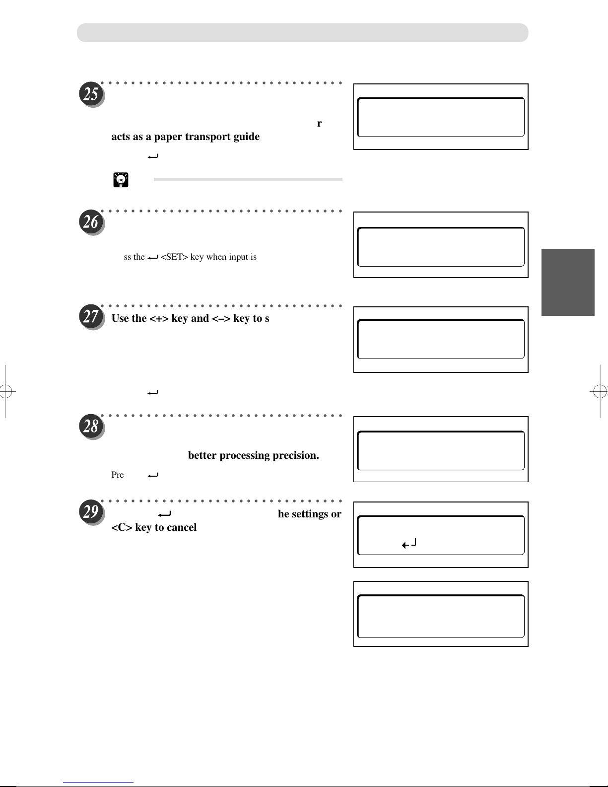
How to Program Job on Control Panel
○○○○○○○○○○○○○○○○○○○○○○○○○○○○○○○○
Use the <+> key and <–> key to switch between
and turn ON/OFF the Slit Guide function.
When this function is ON, the unused slitter
acts as a paper transport guide.
Press the <SET>key when the setting is set.
Tip
• TurnONonlywhenthedocumentweightislight.
○○○○○○○○○○○○○○○○○○○○○○○○○○○○○○○○
Use the <+> key and <–> key to switch between
and turn ON/OFF.
Pressthe <SET>keywheninputiscompleted.
SLIT GUIDE ON
AUTO CUT
OFF
∗
ON
∗
OFF
1
○○○○○○○○○○○○○○○○○○○○○○○○○○○○○○○○
Use the <+> key and <–> key to switch the
creasing depth between and set MAX, Mid or
MIN.
The crease will be deep when MAX is set and
will be shallow when MIN is set.
Pressthe <SET>keywheninputiscompleted.
○○○○○○○○○○○○○○○○○○○○○○○○○○○○○○○○
Use the <+> key and <–> key to switch between
and set High or Low processing speed.
Set to LOW for better processing precision.
Pressthe <SET>keywheninputiscompleted.
○○○○○○○○○○○○○○○○○○○○○○○○○○○○○○○○
Press the <SET> key to retain the settings or
<C> key to cancel the settings.
[MEMORY !!] is displayed when the JOB is
saved on the DC-645 memory circuit.
The memorization process will take approximately 1.5
seconds.
CREASE DEPTH
MAX
SPEED
MID MIN
∗
HIGH
∗
LOW
OVER WRITE ?
OK( ) NO(C)
3
Programing JOB for DC-645 on Control Panel
MEMORY !!
63
Page 65
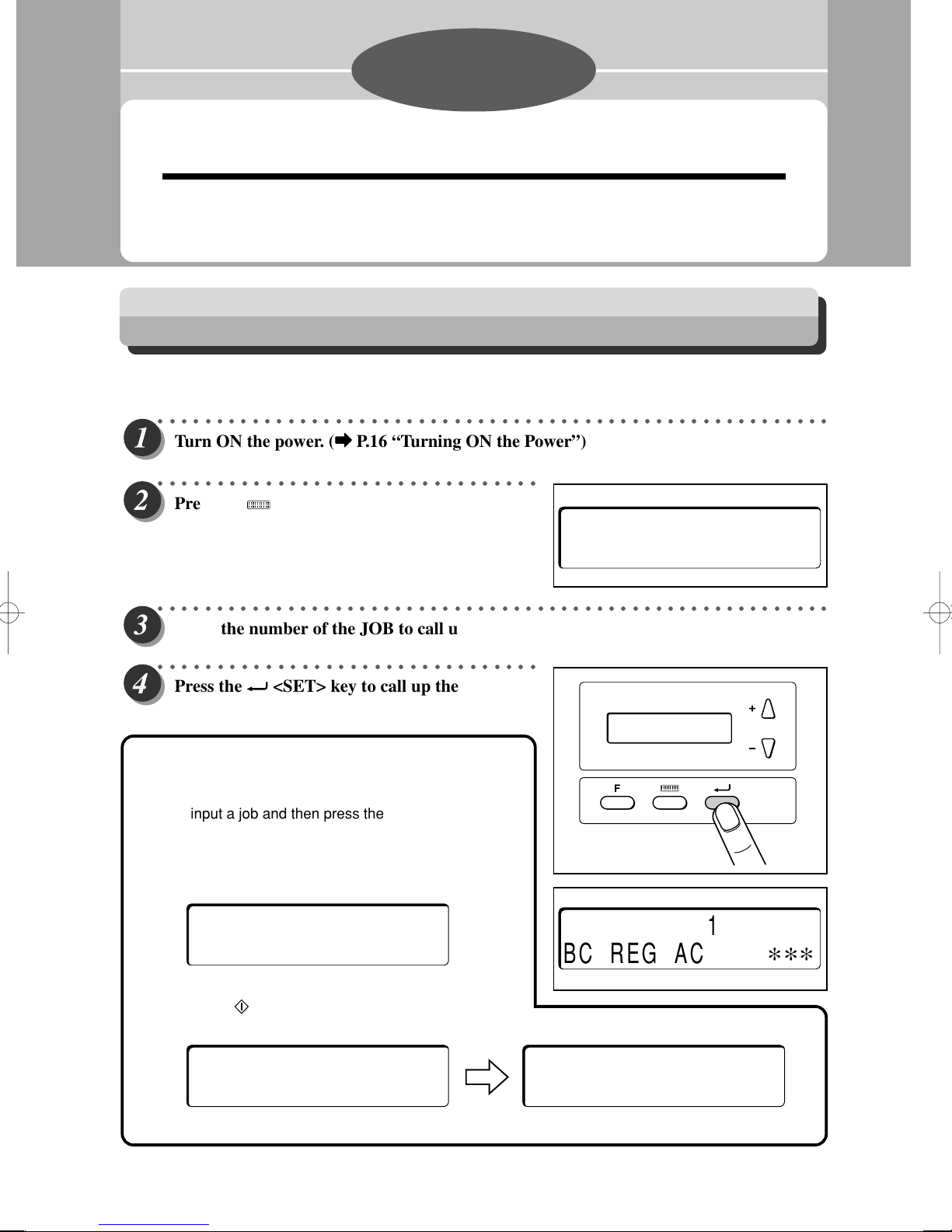
Chapter 4
Basic Operations
This chapter describes the operating sequence from turning ON the power switch until completing
finishing process.
Process Documents by Selecting JOB
This section describes the procedures to process documents by selecting each JOB manually.
○○○○○○○○○○○○○○○○○○○○○○○○○○○○○○○○○○○○○○○○○○○○○○○○○○○○○○○○○
Turn ON the power. (
○○○○○○○○○○○○○○○○○○○○○○○○○○○○○○○○
Press the <MODE> key and go to the
[SELECT] display.
aa
a P.16 “Turning ON the Power”)
aa
[
SELECT
]
05:DUPLO
○○○○○○○○○○○○○○○○○○○○○○○○○○○○○○○○○○○○○○○○○○○○○○○○○○○○○○○○○
Input the number of the JOB to call up, using the <Number> key.
○○○○○○○○○○○○○○○○○○○○○○○○○○○○○○○○
Press the <SET> key to call up the JOB of
the number input.
How to execute batch counting
• The specified number of document are processed.
Select or input a job and then press the <Number> key in
standby state (excluding SELECT/INPUT display) to input the
number of document for batch counting. (The specified
number of document is displayed in the lower right portion of
the control panel.)
∗ ∗
100/100
(Ex.: When 100 documents are set, the above display appears.)
By pressing the <START> key, processed number of the
document is subtracted from the specified number as below.
06:DUPLO 1
BC REG AC
F
∗ ∗ ∗
∗ ∗
99/100
* If an error has occurred during processing, batch counting can not be executed.
64
∗ ∗
98/100
Page 66
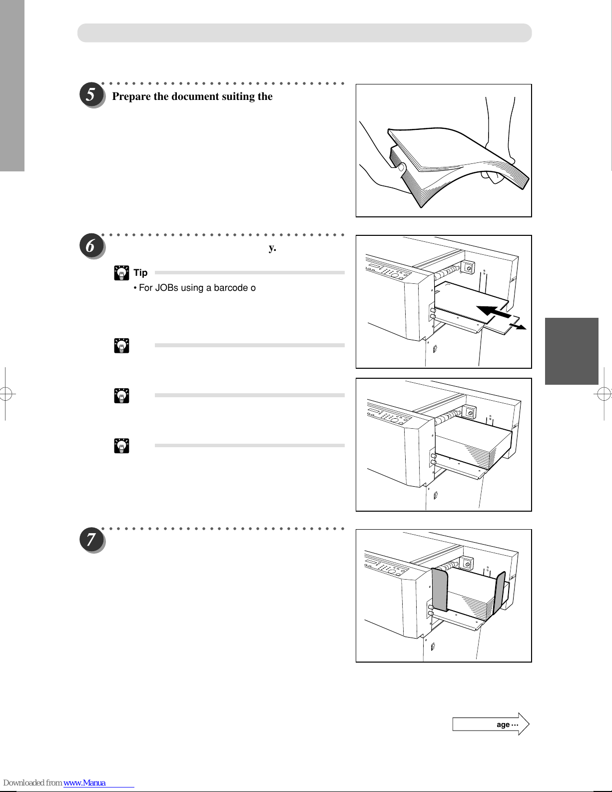
Process Documents by Selecting JOB
○○○○○○○○○○○○○○○○○○○○○○○○○○○○○○○○
Prepare the document suiting the JOB selected,
then loosen the stack of the documents by
flipping through the sheets.
○○○○○○○○○○○○○○○○○○○○○○○○○○○○○○○○
Set the document on the feed tray.
Tip
• For JOBs using a barcode or REG. Mark, place
the barcode and REG. Mark printing side facing
upward as in the illustration. Then set it in the
feed direction.
Tip
• The height of the paper stack should not exceed
the “MAX” level.
Tip
• To set paper that is vertically long, pull out the
feed tray to accommodate the length of paper.
Tip
• Fully extend the hand-feeding paper-feeder for
use.
○○○○○○○○○○○○○○○○○○○○○○○○○○○○○○○○
Set the side guides.
1
4
Basic Operations
Continue Page
•••
65
Page 67
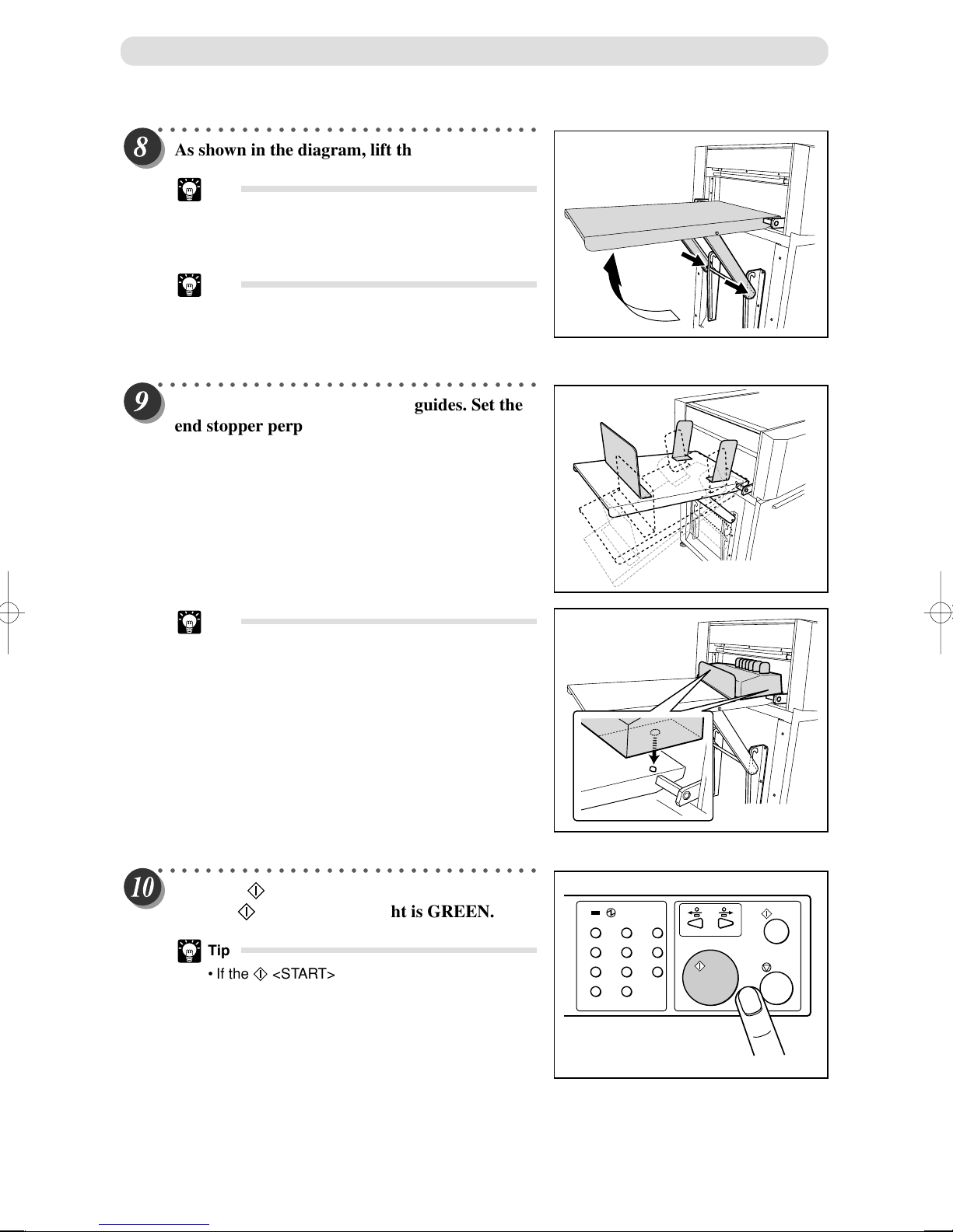
Process Documents by Selecting JOB
○○○○○○○○○○○○○○○○○○○○○○○○○○○○○○○○
As shown in the diagram, lift the stacker tray.
Tip
• When the finished document size is A3 (11” x
17”) or longer, it is recommended to set the
stacker tray in the downward position.
Tip
• If the finished documents are adhere on the tray
due to static electricity, set the stacker tray in the
downward position.
○○○○○○○○○○○○○○○○○○○○○○○○○○○○○○○○
Install the end stopper and side guides. Set the
end stopper perpendicular to the floor.
Tip
• If the document size processed is postcard or
business card size, then it is better to set the
“Card stacker” in place of the guide.
○○○○○○○○○○○○○○○○○○○○○○○○○○○○○○○○
Press the <START> key after confirming
that the <START> key light is GREEN.
Tip
• If the <START> key light is RED.
DC-645 is running a job or having an error.
123
456
789
C
0
66
Page 68
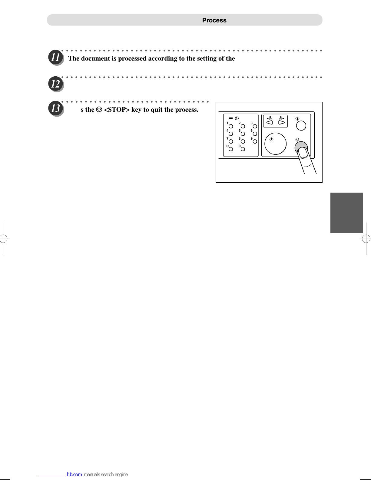
Process Documents by Selecting JOB
○○○○○○○○○○○○○○○○○○○○○○○○○○○○○○○○○○○○○○○○○○○○○○○○○○○○○○○○○
The document is processed according to the setting of the JOB selected.
○○○○○○○○○○○○○○○○○○○○○○○○○○○○○○○○○○○○○○○○○○○○○○○○○○○○○○○○○
The finished document is ejected to the stacker tray.
○○○○○○○○○○○○○○○○○○○○○○○○○○○○○○○○
Press the <STOP> key to quit the process.
123
456
789
C
0
1
4
Basic Operations
67
Page 69
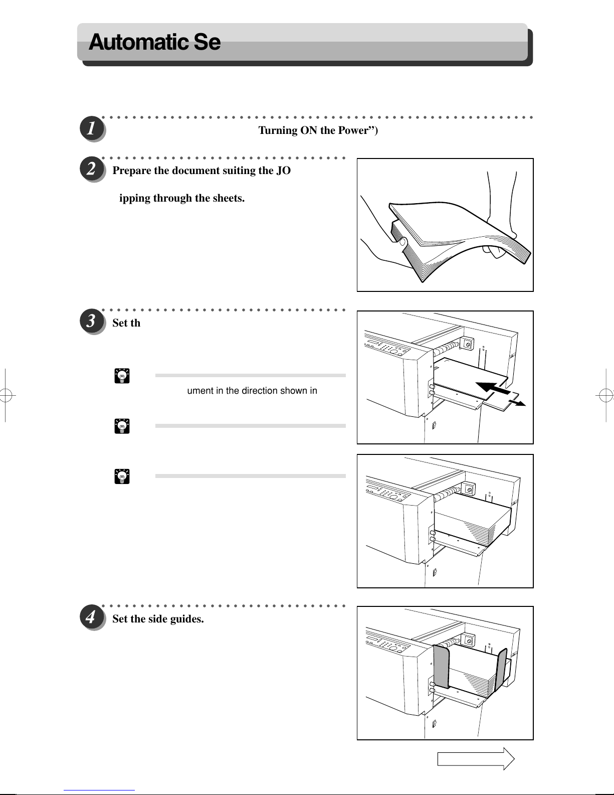
Automatic Set Up Using Barcodes
By adding barcode which indicates job number on each document, DC-645 automatically set up the machine and start
JOB. The procedure is described below.
○○○○○○○○○○○○○○○○○○○○○○○○○○○○○○○○○○○○○○○○○○○○○○○○○○○○○○○○○
Turn ON the power. (
○○○○○○○○○○○○○○○○○○○○○○○○○○○○○○○○
Prepare the document suiting the JOB selected,
then loosen the stack of the documents by
flipping through the sheets.
○○○○○○○○○○○○○○○○○○○○○○○○○○○○○○○○
Set the document in the feed tray with the
surface where barcodes and REG. Marks are
printed facing upwards.
aa
a P.16 “Turning ON the Power”)
aa
Tip
• Set the document in the direction shown in the
illustration.
Tip
• The height of the paper stack should not exceed
the “MAX” level.
Tip
• To set paper that is vertically long, pull out the
feed tray to accommodate the length of paper.
○○○○○○○○○○○○○○○○○○○○○○○○○○○○○○○○
Set the side guides.
68
Continue Page
•••
Page 70
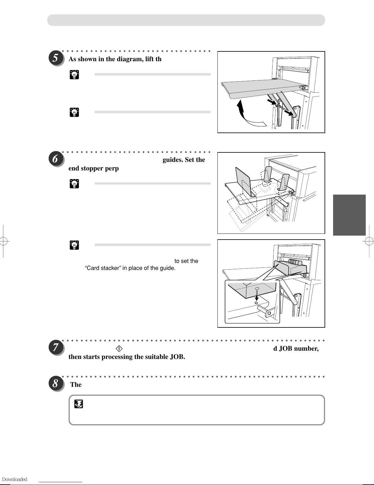
○○○○○○○○○○○○○○○○○○○○○○○○○○○○○○○○
As shown in the diagram, lift the stacker tray.
Tip
• When the finished document size is A3 (11” x
17”) or longer, it is recommended to set the
stacker tray in the downward position.
Tip
• If the finished documents are adhere on the tray
due to static electricity, set the stacker tray in the
downward position.
○○○○○○○○○○○○○○○○○○○○○○○○○○○○○○○○
Install the end stopper and side guides. Set the
end stopper perpendicular to the floor.
Tip
• If the document size processed is postcard or
business card size, then it is better to set the
“Card stacker” in place of the guide.
Automatic Set Up Using Barcodes
Tip
• If the document size processed is postcard or
business card size, then it is better to set the
“Card stacker” in place of the guide.
○○○○○○○○○○○○○○○○○○○○○○○○○○○○○○○○○○○○○○○○○○○○○○○○○○○○○○○○○
By pressing the <START> key, the built-in CCD reads the barcoded JOB number,
then starts processing the suitable JOB.
○○○○○○○○○○○○○○○○○○○○○○○○○○○○○○○○○○○○○○○○○○○○○○○○○○○○○○○○○
The finished document is ejected.
1
4
Basic Operations
IMPORTANT
• Pieces of cut paper accumulate in the waste box. Open the front cover and remove them
periodically. Accumulation of pieces of paper may cause paper jams.
69
Page 71
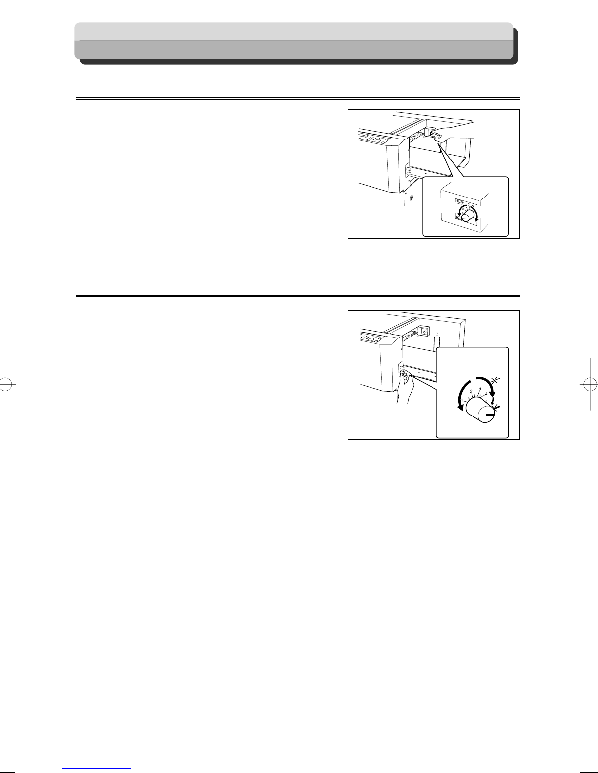
Adjust Feeder
Elevator level (Feed tray)
The elevator level should be adjusted in the following
cases.
a. The machine does not feed.
→ Turn the knob in the clockwise direction. (to a
larger number)
The level of the elevator is raised.
b. The machine feeds multiple sheets at once.
(double feed)
→
Turn the knob in the anti-clockwise direction. (to
a smaller number).
The level of the elevator is lowered.
Separator
The height of the separator should be adjusted in the
following cases:
a. The machine does not feed.
→
Turn the knob in the clockwise direction (to a
larger number). The position of the separator is
lowered.
b. The machine feeds multiple sheets at once.
(double feed)
→
Turn the knob in the anti-clockwise direction (to
a smaller number). The position of the separator
is raised.
For Light
Paper
Level adjustment knob
For Light
Paper
Separator adjustment knob
For Heavy
Paper
For Heavy
Paper
70
Page 72
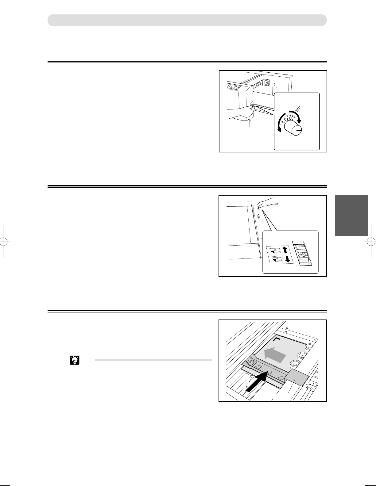
Airflow
The amount of airflow should be adjusted in the following
cases:
a. The machine does not feed.
→
Turn the knob in the clockwise direction (to a
larger number). The amount of airflow is
increased.
b. The machine feeds multiple sheets at once.
(double feed)
→
Turn the knob in the anti-clockwise direction (to
a smaller number). The amount of airflow is
decreased.
Print Image Skew
If the document to cut is printed obliquely, then the finish
may not be as expected. When this happens, correct the
problem by changing the angle of the feed guide.
Airflow adjustment knob
Adjust Feeder
For Heavy
Paper
For Light
Paper
1
4
Skew adjustment knob
Curled Document / Light Weight Document
If the document is light weight paper or curled, the paper
rolls up between the unit and will not be successfully fed.
In such case, adjust the position of the upper guide so that
the edge of the document passes under the upper guide.
Tip
• Do not use the upper guide when feeding
document is not light weight or curled.
Basic Operations
Upper guide
71
Page 73

FUNCTION Mode
Various mechanical settings are set when processing takes place.
AIR KNIFE Compressed air is blown out to loosen the document. This is to prevent double-feed.
FAN REG. Document skewing in feeding area is corrected. When processing light weight document, turn this
function OFF as it may cause a paper jam in feed area.
DOUBLE FEED This detects whether the document is double-feed. Always leave ON.
BARCORD This sets whether to execute automatic setup when reading the barcode.
REG. MARK This sets whether to detect the REG. Mark. The Document processing precision can be heightened
by detecting the REG. Mark and setting the process to the standard (home) location.
REJECT Double-fed documents or documents with inappropriate BARCODE or REG. Mark (when these
functions are on) are rejected on the reject tray automatically.
SLIT GUIDE When any slitters are not used, these slitters act as paper guide to stabilize the paper conveyance.
Recommended for light weight document.
AUTO CUT Lead margin, trail margin, and any gutter cuts (shorter than 85 mm) are finely cut and dropped into
the waste box. When documents do not have lead margins or trail margin, this must be turned off.
CREASE DEPTH This sets the depth of the crease when creasing a document. Set to MAX for heavy paper and MIN
for light paper.
SPEED This is used to select HIGH/LOW processing speed.
APPLY SHRINKAGE
In case printed documents are shrunk by heat generated on digital printer, by entering the original
paper size and paper size after shrinked, DC-645 automatically calculate the shrinkage ratio and
adjust the cutting & creasing position accordingly. This function compensate for the shrinkage in
the feed direction only.
Tip
• The DC-645 comes with a function to stop the JOB when a certain number of documents are
rejected when processing the document. This function is generally set by the servicing
personnel upon the initial setup. This setting can be changed from the “Settings” menu of the
JOB Creator.
(a P.49 “Setting Frequent Function From Computer (“Function Setting”)”)
Function Mode Flow Chart
IMPORTANT
• Functions of AIRKNIFE, FAN REG., REG.
MARK, SLIT GUIDE, AUTO CUT, CREASE
DEPTH, and SPEED are also set ON/OFF
when programing JOB.
Settings memorized when programing JOB
take priority over those by <F> key. Therefore,
settings by <F> key apply only to the process
which is just after the settings. Programmed
settings are not overwhitten and remain as
they are.
On the contrary, functions of DOUBLE FEED,
BARCODE, REJECT, AND APPLY
SHRINKAGE are set ON/OFF only by <F>
key.
AIR KNIFE
FAN. REG
DOUBLE FEED
BARCODE
REG. MARK
REJECT
SLIT GUIDE
AUTO CUT
CREASE DEPTH
SPEED
72
APPLY SHRINKAGE
Page 74

■ Setup Procedures
○○○○○○○○○○○○○○○○○○○○○○○○○○○○○○○○
Press the <F> key to switch to the Function
Mode.
FUNCTION Mode
F
AIR KNIFE ON
○○○○○○○○○○○○○○○○○○○○○○○○○○○○○○○○
Press the <SET> key several times, to
display the Function to set.
○○○○○○○○○○○○○○○○○○○○○○○○○○○○○○○○
Set ON/OFF with the <+> key or <–> key.
F
OFF
∗
AIR KNIFE ON
OFF
∗
1
4
Basic Operations
○○○○○○○○○○○○○○○○○○○○○○○○○○○○○○○○○○○○○○○○○○○○○○○○○○○○○○○○○
Press the <F> key to return to the regular display.
F
AIR KNIFE ON
OFF
∗
73
Page 75

About the Waste Box
Pieces of cut paper accumulate in the waste box.
How to remove the accumulated pieces of paper is described below.
WARNING
• Be sure to confirm that the machine is in a full stop before removing the accumulated
paper to prevent your hands or fingers from being caught or pinched in the machine.
IMPORTANT
• Accumulation of pieces of paper may cause paper jams. Remove the paper scraps from the
waste box described below.
○○○○○○○○○○○○○○○○○○○○○○○○○○○○○○○○○○○○○○○○○○○○○○○○○○○○○○○○○
Confirm that the machine is fully stopped.
○○○○○○○○○○○○○○○○○○○○○○○○○○○○○○○○
Open the front cover located at the bottom left
of the machine and remove the accumulated
paper in the waste box.
Tip
• When pieces of paper remain in the machine,
remove them.
○○○○○○○○○○○○○○○○○○○○○○○○○○○○○○○○○○○○○○○○○○○○○○○○○○○○○○○○○
Close the front cover.
74
Page 76

Clean Feed Rollers
As DC-645 process digital colour outputs, toner etc. on the documents may adhere to the surface of feed rollers of DC-
645. When the accumulation of such toner becomes excessive, it may effect the performance of DC-645. In this case,
clean the rollers in following procedures.
○○○○○○○○○○○○○○○○○○○○○○○○○○○○○○○○
Press the “ | ” side of the power switch, while
pressing the <MODE> key, to turn ON the
machine.
The machine is started up with the Cleaning
Mode.
CLEANING MODE
STOP–>POWER OFF
F
○○○○○○○○○○○○○○○○○○○○○○○○○○○○○○○○
Open / Close Top Cover 1.
Every time the top cover (1) is opened/closed,
the feed rollers turn 60 degrees. Wipe-off the
toner, debris on the rollers using a tightly
wrung cloth. The entire roll is cleaned around
its circumference by opening/closing the top
cover 6 times.
IMPORTANT
• Do not wipe the rollers with anything other
than that designated above. Use of anything
else may result in mechanical malfunction.
○○○○○○○○○○○○○○○○○○○○○○○○○○○○○○○○
Press the power switch of the “
OFF the power and quit the Cleaning Mode.
KK
K ” side to turn
KK
1
4
Basic Operations
75
Page 77

Chapter 5
Troubleshooting
This chapter describes what to do when an error has occurred and how to deal with paper jams and error
messages.
Troubleshooting Flow Chart
Power Does Not Turn ON
If the power does not turn ON, check the following.
THE MACHINE DOES NOT TURN ON.
IS POWER PLUG INSERTED?
IS POWER SWITCH ON?
NOYES
Turn the power switch ON.
Please contact your service personnel.
NOYES
Insert the power
plug securely.
76
Page 78

Cutting is Not Possible
If cutting is not possible, check the following.
IS THERE A MESSAGE DISPLAYED
ON LCD PANEL AND OK MONITOR?
Troubleshooting Flow Chart
NO
Please contact your service person.
YES
See P.78 “OK Monitor Display and Jam Display”,
P.80 “Error Display”,
and P.82 “Warning Display”.
25
Troubleshooting
77
Page 79

OK Monitor Display and Jam Display
When a paper jam or error that the machine cannot correct occurs, the OK monitor will flash where the error occurred.
The LCD panel will display JAM.
In such case, following the procedures below to resolve the cause.
Message Countermeasure
COVER OPEN
PLEASE SET PAPER
OVER CAPACITY (J7)
FEED JAM (J2)
The top or front cover is open.
Close the top or front cover.
There is no paper in the feed tray.
Load the feed tray with paper.
Too many document stacked in the feed tray.
Remove the document in the machine and press the <STOP> key.
(a P.97 “When “OVER CAPACITY” is displayed”)
This is paper jam in the feed tray or skew correction area.
Remove the document in the machine and press the <STOP> key.
(a P.85 “When “FEED JAM” is displayed”)
1. Satisfactorily fan the edge of the paper stack in the feed tray.
2. Adjust the feed. (a P.70 “Adjust Feeder”)
CENTER JAM (J3) Paper jam in the CCD or slitter area.
78
Remove the document in the machine and press the <STOP> key.
(a P.87 “When “CENTER JAM” is displayed”)
Page 80
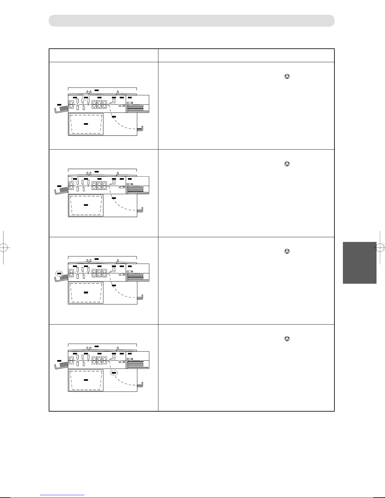
OK Monitor Display and Jam Display
Message Countermeasure
CUTTER OR CREASE (J4) This is a paper jam in the cutter module or crease area.
Remove the document in the machine and press the <STOP> key.
(a P.89 “When “CUTTER OR CREASE” is displayed”)
OPTIONAREAJAM(J5)
STACKERJAM(J6)
REJECTAREAJAM(J8) Paper jam in the reject area.
Paper jam in the optional module.
Remove the document in the machine and press the <STOP> key.
(a P.93 “When “OPTION AREA JAM” is displayed”)
Paper jam in the stacker unit.
Remove the document in the machine and press the <STOP> key.
(a P.95 “When “STACKER JAM” is displayed”)
Remove the document in the machine and press the <STOP> key.
(a P.98 “When “REJECT AREA JAM” is displayed”)
25
Troubleshooting
79
Page 81
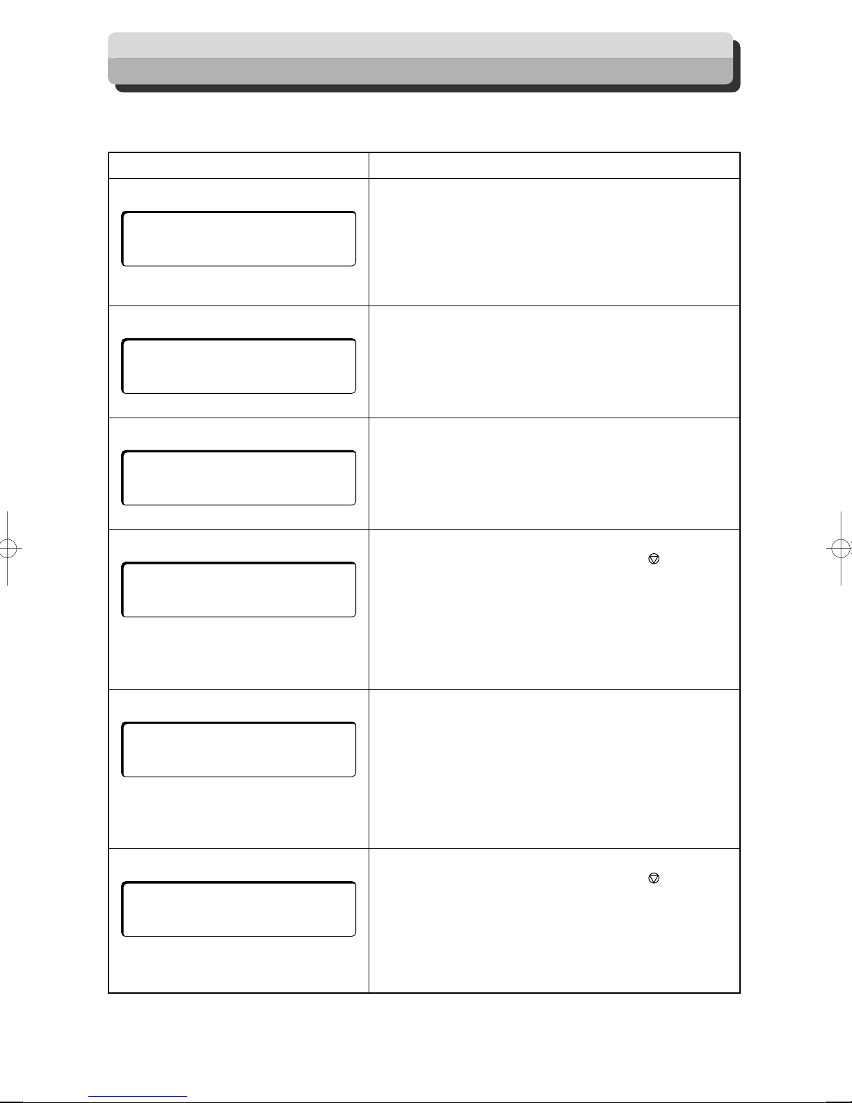
Error Display
When an error that the machine cannot correct occurs, an Error message is displayed on the LCD panel.
In such case, take measures according to the following instructions.
Message Countermeasure
RS232C ERROR (E2)
––– E 2 –––
RS232C ERROR
BARCODE ERROR (E3)
––– E 3 –––
BARCODE ERROR
REG.MARK ERROR (E4)
––– E 4 –––
REG. MARK ERROR
SLITTER ERROR (E5)
––– E 5 –––
SLITTER ERROR
* The slitter number in error is displayed.
DATA ERROR (E6)
∗
––– E 6 –––
Communication error between the CCD and the mainboard.
1. Turn OFF the power. Then turn ON the power again, to reset the
machine.
2. Contact the service personnel if the ERROR message remains
displayed.
This is a barcode reading error.
1. Verify the barcode on the document is printed clearly.
2. Check the location of barcode.
See “Specifications of REG. Mark and Barcode” for details.
This is a REG. Mark reading error.
1. Verify the documents REG. Mark is printed clearly.
2. Check the location of the barcode.
See “Specifications of REG. Mark and Barcode” for details.
This is a slitter module error.
Remove the document in the machine and press the <STOP>
key.
(a P.87 “When “CENTER JAM” is displayed”)
1. Turn OFF the power. Then turn ON the power again.
2. Carefully open the Top Cover 2, then check for any paper in the
operating range of slitter area. If there is any paper identified,
carefully remove it.
3. Contact the service personnel.
There is no JOB programmed in selected JOB no.
1. Confirm the JOB no. and select a proper one.
2. Program a new JOB in the JOB no. if necessary.
DATA ERROR
CUTTER ERROR (E7)
––– E 7 –––
CUTTER ERROR
80
This is a cutter error.
Remove the document in the machine and press the <STOP>
key.
(a P.89 “When “CUTTER OR CREASE” is displayed”)
1. Turn OFF the power. Then turn ON the power again.
2. Carefully open the Top Cover 3. Check for any paper in cutter
area. If there is any paper identified, carefully remove it.
3. Contact the service personnel.
Page 82
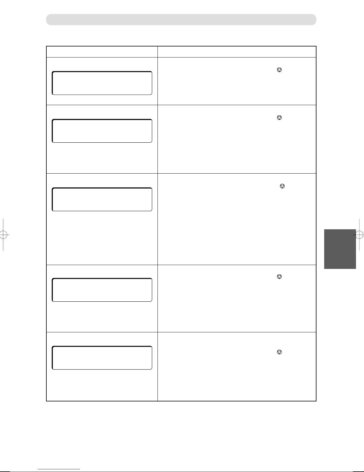
Message Countermeasure
Error Display
ELEVATOR ERROR (E8)
––– E 8 –––
ELEVATOR ERROR
CREASE ERROR (E9)
––– E 9 –––
CREASE ERROR
DOUBLE FEED (E11)
––– E 11 –––
DOUBLE FEED
REJECT ERROR (E12)
––– E 12 –––
REJECT ERROR
GUTTER ERROR (E14, 15)
––– E 14 –––
GUTTER ERROR R
This is an elevator error.
Remove the document in the machine and press the <STOP>
key.
1. Turn OFF the power. Then turn ON the power again, to reset the
machine.
2. Contact the service personnel.
This is a creaser module error.
Remove the document in the machine and press the <STOP>
key.
(a P.89 “When “CUTTER OR CREASE” is displayed”)
1. Turn OFF the power. Then turn ON the power again.
2. Carefully open the Top Cover 3. Check to see if there are any
paper in the operation range of the creaser module. If there is any
paper identified, carefully remove it.
3. Contact the service personnel.
Double-feed was detected.
Remove the document in the machine, then press the <STOP>
key.
1. Turn OFF the power. Then turn ON the power again, to reset the
machine.
2. Satisfactorily flip through and loosen the document sheets in the
feed tray.
3. Adjust the feed. (a P.70 “Adjust Feeder”)
4. The Double-Feed Error is displayed when the Double-Feed
Detection is ON and Reject is OFF.
By keeping Reject ON, the detected document will automatically
be output to the reject tray.
This is an error in the reject area.
Remove the document in the machine and press the <STOP>
key.
(a P.98 “When “REJECT AREA JAM” is displayed”)
1. Turn OFF the power. Then turn ON the power again.
2. Carefully open the front cover. Then check if there are any paper
in the reject area. If there is any paper identified, carefully
remove it.
3. Contact the service personnel.
This is displayed when the gutter guide does not return to the home
position within a designated time.
Remove the document in the machine and press the <STOP>
key.
1. Turn OFF the power. Then turn ON the power again.
2. Carefully open Top Cover 3. Check to see if there are any paper
in the operation range of the gutter deflector. If there is any paper
identified, carefully remove it.
3. Contact the service personnel.
25
Troubleshooting
81
Page 83
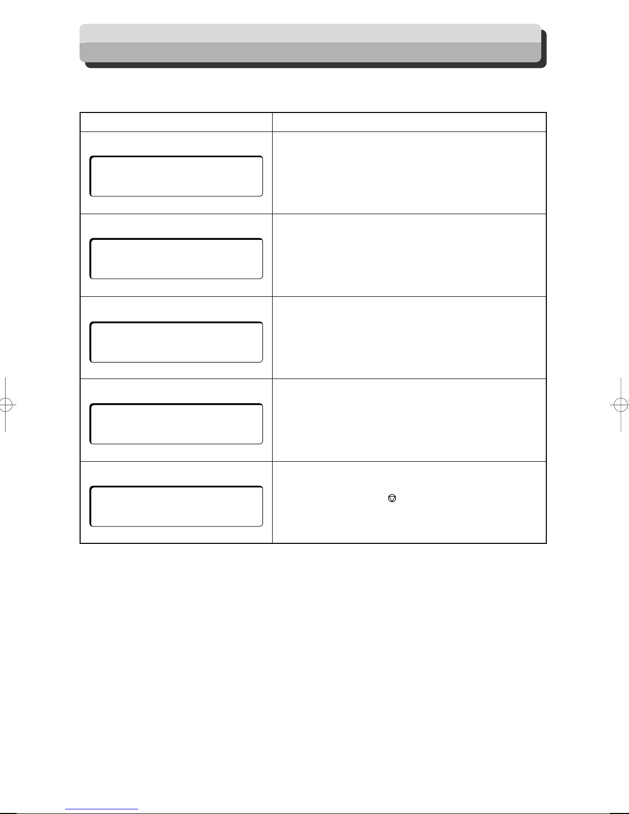
Warning Display
A warning display appears on the LCD panel when attempting to process a JOB when the machine is not ready.
In such case, take measures according to the following instructions.
Message Countermeasure
CHANGE MODULE
CHANGE MODULE
STANDARD
SET SLIT MODULE
SET SLIT MODULE
COVER OPEN
COVER OPEN
BLANK DATA
BLANK DATA
A module not specified in the JOB selected is set on the machine.
Set the optional module of the machine to the module displayed on
the LCD panel.
There is no slitter module.
Install a slitter module in the machine.
One or more slitter module is not set in the machine.
The top or front cover is open.
Close the top or front cover.
Program a new JOB in the JOB no. if necessary.
USB-IF SUSPENDED
USB–IF SUSPENDED
The machine is out of communication with a computer.
(When a computer is in standby status or sleep status, wake up the
computer and then press the <STOP> key to cancel the error.)
1. Turn OFF this machine. Then pull out and re-insert the USB
cable.
2. Contact the servicing personnel.
82
Page 84
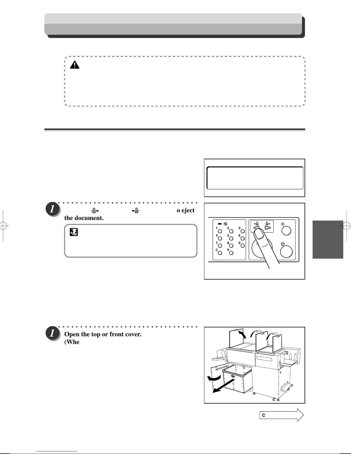
When a Paper Jam Has Occurred
When a paper jam has occurred, the lamp blinks on the OK monitor and a message is displayed on the LCD panel.
WARNING
• Do not touch the blade (with the WARNING sticker attached). Doing so may cause injury.
(aP.7, “Warning Sticker”)
• Before removing paper make sure the machine is fully stopped. Use the pliers that come
with the machine to prevent your hands or fingers from being caught or pinched.
(aP.7, “Warning Sticker”)
When “REJECT PAPER” is Displayed
If a document remains in the machine when the power is turned ON, “REJECT PAPER” is displayed on the
LCD panel and the lamp blinks on the OK monitor.
Remove the document with the following procedure.
––– J 1 –––
REJECT PAPER
○○○○○○○○○○○○○○○○○○○○○○○○○○○○○○○○
Press the <JOG> or <JOG> key to eject
the document.
IMPORTANT
• Be sure to close the top and front cover when
you operate the machine. The machine does
not work if the top or front cover is open.
123
456
789
C
0
■ If the document cannot be removed with the procedure mentioned above
○○○○○○○○○○○○○○○○○○○○○○○○○○○○○○○○
Open the top or front cover.
(When the front cover is opened)
Remove the waste box.
25
Troubleshooting
Continue Page
•••
83
Page 85
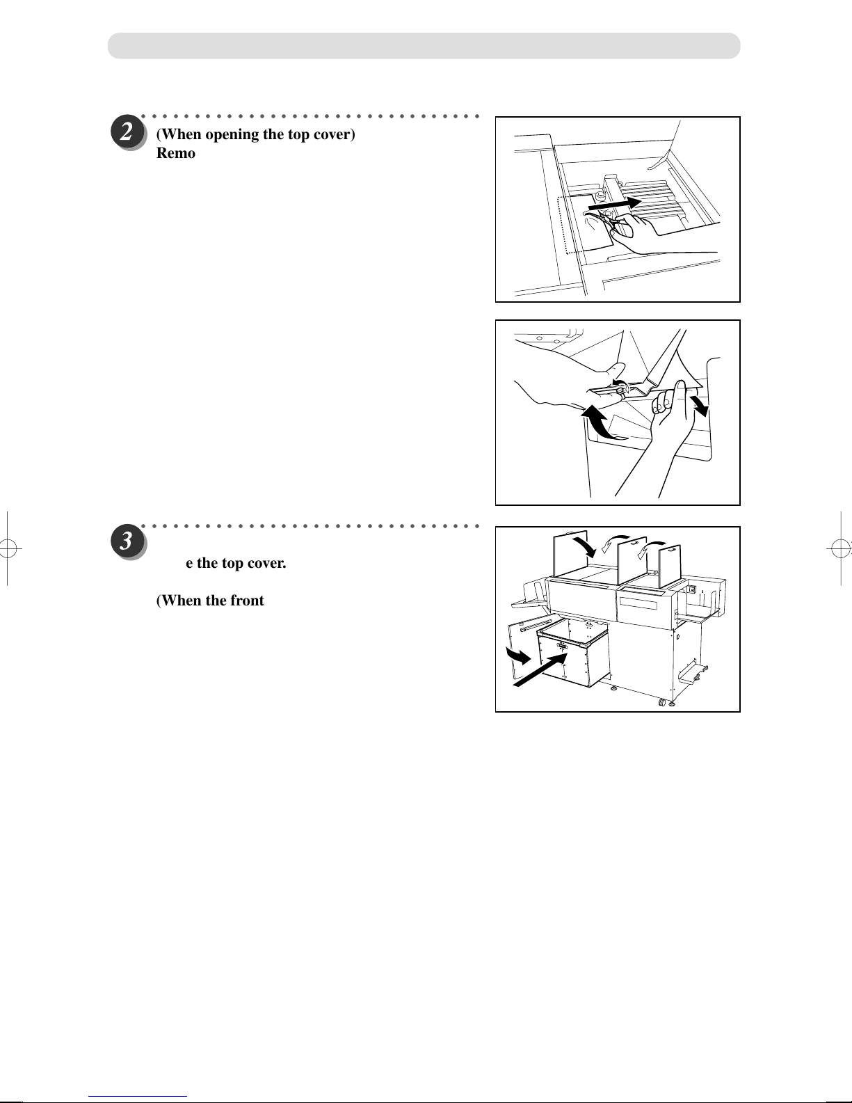
When a Paper Jam Has Occurred
○○○○○○○○○○○○○○○○○○○○○○○○○○○○○○○○
(When opening the top cover)
Remove the jammed document using your
fingers or the pliers.
(When the front cover is opened)
Loosen the guide screw for the paper outlet. Lift
it forward and remove the paper jam.
○○○○○○○○○○○○○○○○○○○○○○○○○○○○○○○○
(When opening the top cover)
Close the top cover.
(When the front cover is opened)
Loosen the guide screw. Put the waste box
inside. Then close the front cover.
84
Page 86
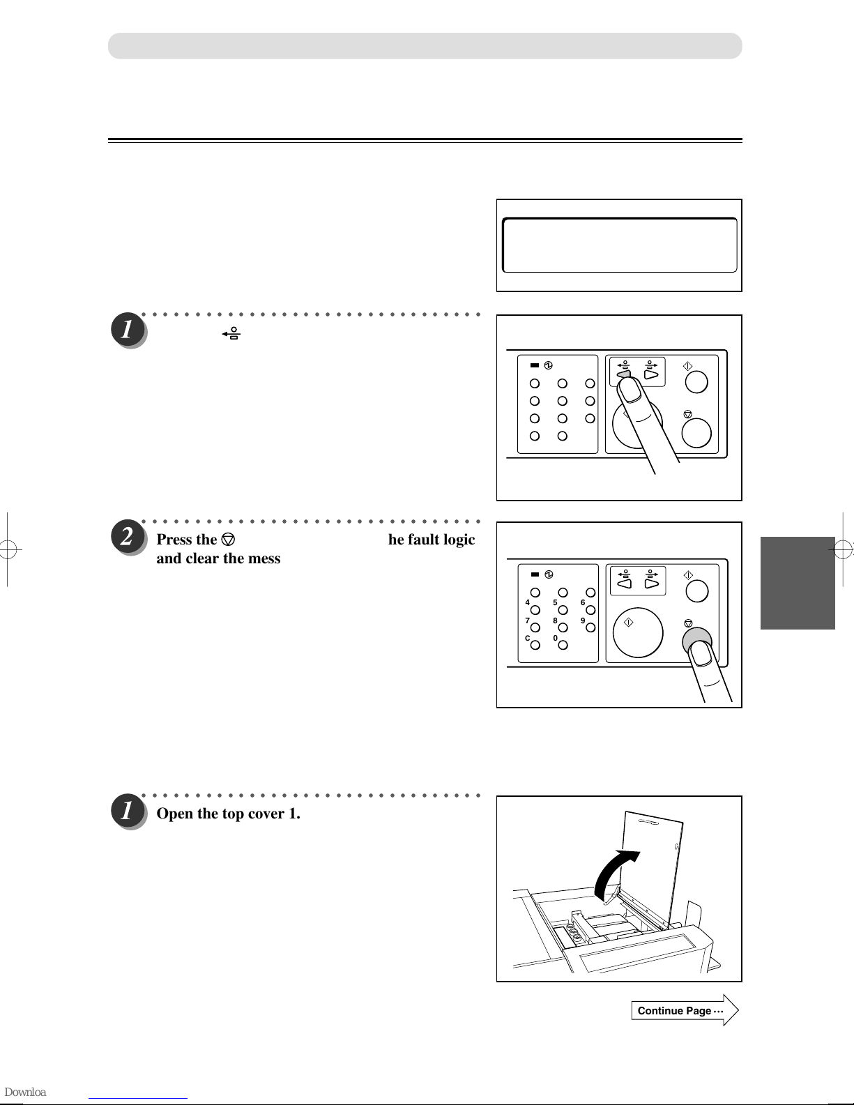
When “FEED JAM” is Displayed
If a paper jam has occurred in the feeding area, “FEED JAM” is displayed on the LCD panel and the lamp
blinks on the OK monitor.
Remove the jammed document with the following procedure.
○○○○○○○○○○○○○○○○○○○○○○○○○○○○○○○○
Press the <JOG> key to eject the jammed
documents.
When a Paper Jam Has Occurred
––– J 2 –––
FEED JAM
123
456
789
C
0
○○○○○○○○○○○○○○○○○○○○○○○○○○○○○○○○
Press the <STOP> key to reset the fault logic
and clear the message.
123
456
789
C
0
■ If the document cannot be removed with the procedure mentioned above
○○○○○○○○○○○○○○○○○○○○○○○○○○○○○○○○
Open the top cover 1.
25
Troubleshooting
Continue Page
•••
85
Page 87

When a Paper Jam Has Occurred
○○○○○○○○○○○○○○○○○○○○○○○○○○○○○○○○
Remove the jammed document using your
fingers or the pliers.
○○○○○○○○○○○○○○○○○○○○○○○○○○○○○○○○
Close the top cover 1.
○○○○○○○○○○○○○○○○○○○○○○○○○○○○○○○○
○○○○○○○○○○○○○○○○○○○○○○○○○○○○○○○○
Press the <STOP> key to reset the fault logic
and clear the message.
123
456
789
C
0
86
Page 88

When “CENTER JAM” is Displayed
If a paper jam has occurred in the slitter area, “CENTER JAM” is displayed on the LCD panel and the lamp
blinks on the OK monitor.
Remove the jammed document with the following procedure.
○○○○○○○○○○○○○○○○○○○○○○○○○○○○○○○○
Press the <JOG> key and eject the jammed
document to the stacker tray side.
When a Paper Jam Has Occurred
––– J 3 –––
CENTER JAM
123
456
789
C
0
○○○○○○○○○○○○○○○○○○○○○○○○○○○○○○○○
Press the <STOP> key to reset the fault logic
and clear the message.
123
456
789
C
0
■ If the document cannot be removed with the procedure mentioned above
○○○○○○○○○○○○○○○○○○○○○○○○○○○○○○○○
Open the top cover 2.
25
Troubleshooting
Continue Page
•••
87
Page 89
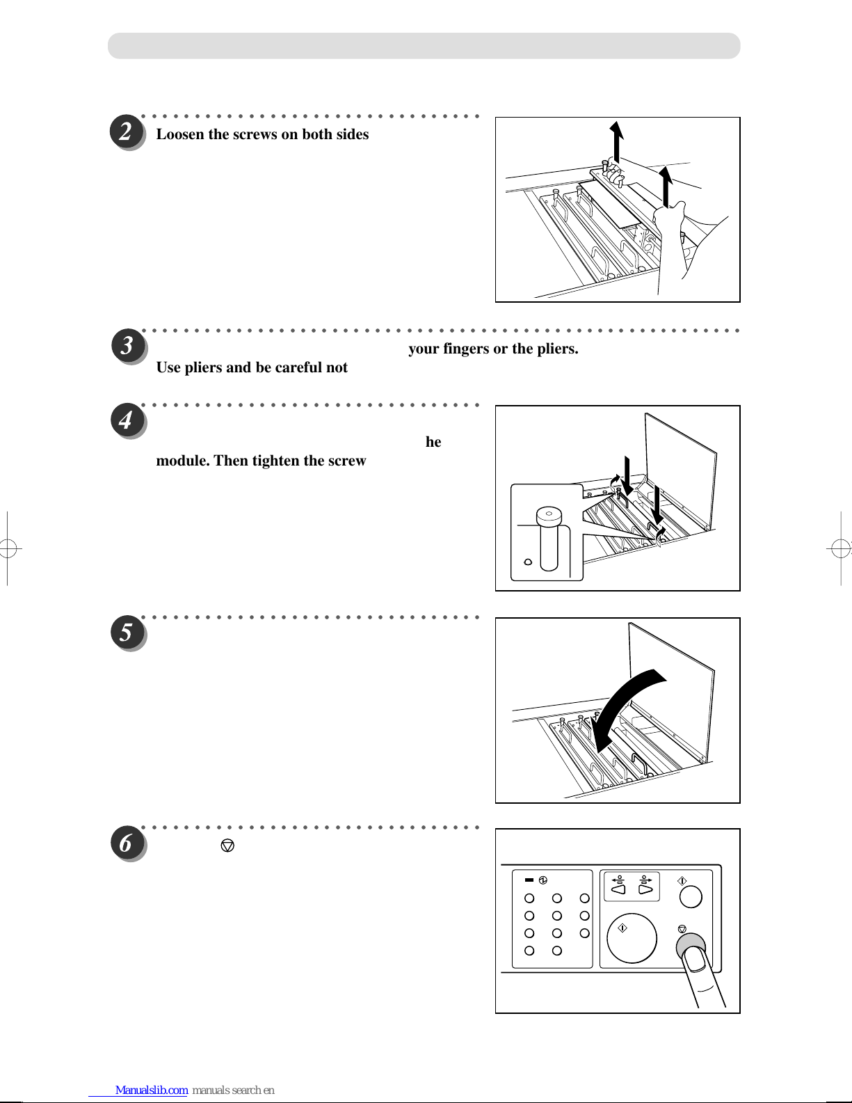
When a Paper Jam Has Occurred
○○○○○○○○○○○○○○○○○○○○○○○○○○○○○○○○
Loosen the screws on both sides of the module
with a paper jam, and lift the module.
○○○○○○○○○○○○○○○○○○○○○○○○○○○○○○○○○○○○○○○○○○○○○○○○○○○○○○○○○
Remove the jammed document using your fingers or the pliers.
Use pliers and be careful not to damage the blade.
○○○○○○○○○○○○○○○○○○○○○○○○○○○○○○○○
Slowly lower the module. Check to see that the
pins on both sides are securely fitted in the
module. Then tighten the screws.
○○○○○○○○○○○○○○○○○○○○○○○○○○○○○○○○
Close the top cover 2.
○○○○○○○○○○○○○○○○○○○○○○○○○○○○○○○○
Press the <STOP> key to reset the fault logic
and clear the message.
123
456
789
C
0
88
Page 90

When a Paper Jam Has Occurred
When “CUTTER OR CREASE” is Displayed
If a paper jam has occurred in the cutter or creaser module, “CUTTER OR CREASE” is displayed on the LCD
panel and the lamp blinks on the OK monitor.
Remove the jammed document with the following procedure.
––– J 4 –––
CUTTER OR CREASE
○○○○○○○○○○○○○○○○○○○○○○○○○○○○○○○○
Press the <JOG> key and eject the jammed
document to the stacker tray side.
123
456
789
C
0
○○○○○○○○○○○○○○○○○○○○○○○○○○○○○○○○
Press the <STOP> key to reset the fault logic
and clear the message.
123
456
789
C
0
■ If the document cannot be removed with the procedure mentioned above
When uninstalling the creaser module:
○○○○○○○○○○○○○○○○○○○○○○○○○○○○○○○○
Open the top cover 3.
25
Troubleshooting
Continue Page
•••
89
Page 91
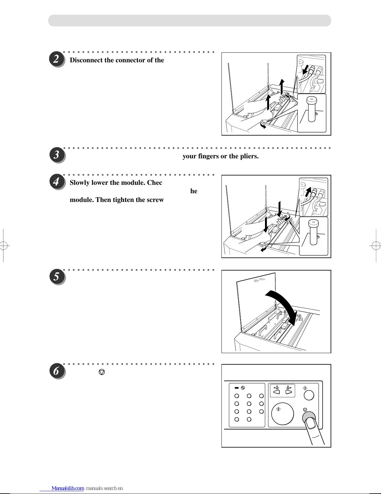
When a Paper Jam Has Occurred
○○○○○○○○○○○○○○○○○○○○○○○○○○○○○○○○
Disconnect the connector of the creaser module.
Then, loosen the screws on both sides of the
module with a paper jam, and lift the module.
○○○○○○○○○○○○○○○○○○○○○○○○○○○○○○○○○○○○○○○○○○○○○○○○○○○○○○○○○
Remove the jammed document using your fingers or the pliers.
○○○○○○○○○○○○○○○○○○○○○○○○○○○○○○○○
Slowly lower the module. Check to see that the
pins on both sides are securely fitted in the
module. Then tighten the screws.
○○○○○○○○○○○○○○○○○○○○○○○○○○○○○○○○
Close the top cover 3.
○○○○○○○○○○○○○○○○○○○○○○○○○○○○○○○○
Press the <STOP> key to reset the fault logic
and clear the message.
123
456
789
C
0
90
Page 92

When uninstalling the cutter module:
○○○○○○○○○○○○○○○○○○○○○○○○○○○○○○○○
Prepare the cutter cover.
○○○○○○○○○○○○○○○○○○○○○○○○○○○○○○○○
Disconnect the connector of the cutter module.
When a Paper Jam Has Occurred
Cutter cover
○○○○○○○○○○○○○○○○○○○○○○○○○○○○○○○○
Unscrew the knob screws on both sides of the
module. (Be careful not to lose or misplace the
screws after unscrewing them.)
○○○○○○○○○○○○○○○○○○○○○○○○○○○○○○○○
○○○○○○○○○○○○○○○○○○○○○○○○○○○○○○○○
Install the cutter cover on the cutter module by
inserting one side of the cutter cover between
the gap, as shown in the diagram.
25
Troubleshooting
Continue Page
•••
91
Page 93

When a Paper Jam Has Occurred
○○○○○○○○○○○○○○○○○○○○○○○○○○○○○○○○
Screw on the knob screws that was unscrewed
in Step 3, in the location shown in the diagram.
○○○○○○○○○○○○○○○○○○○○○○○○○○○○○○○○
Lift the cutter cover by holding the handle
portion while lifting the cutter cover.
92
Disassembled cutter module
Page 94
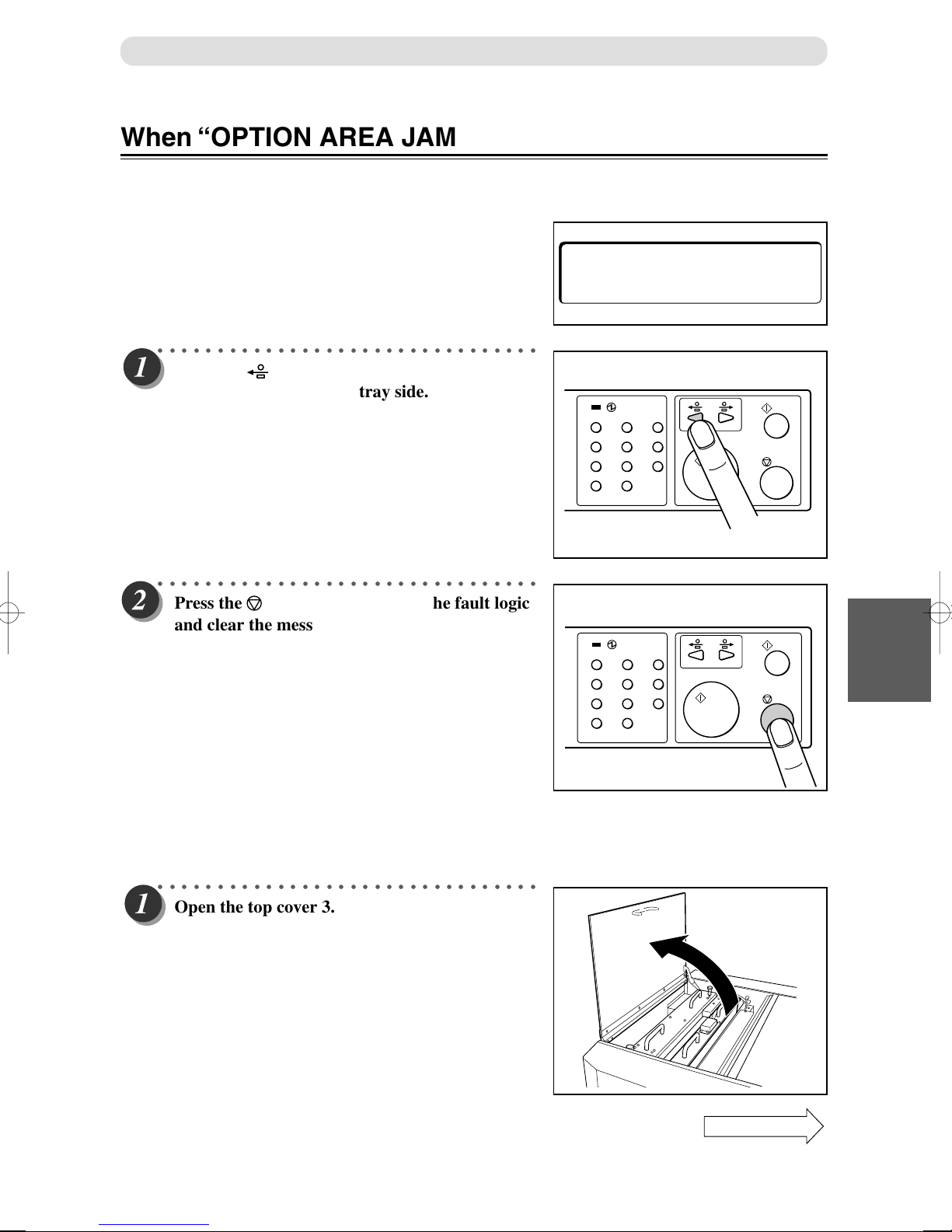
When a Paper Jam Has Occurred
When “OPTION AREA JAM” is Displayed
If a paper jam has occurred in the optional module, “OPTION AREA JAM” is displayed on the LCD panel and
the lamp blinks on the OK monitor.
Remove the jammed document with the following procedure.
––– J 5 –––
OPTION AREA JAM
○○○○○○○○○○○○○○○○○○○○○○○○○○○○○○○○
Press the <JOG> key and eject the jammed
document to the stacker tray side.
123
456
789
C
0
○○○○○○○○○○○○○○○○○○○○○○○○○○○○○○○○
Press the <STOP> key to reset the fault logic
and clear the message.
123
456
789
C
0
■ If the document cannot be removed with the procedure mentioned above
○○○○○○○○○○○○○○○○○○○○○○○○○○○○○○○○
Open the top cover 3.
25
Troubleshooting
Continue Page
•••
93
Page 95

When a Paper Jam Has Occurred
○○○○○○○○○○○○○○○○○○○○○○○○○○○○○○○○
Loosen the screws on both sides of the module
with a paper jam, and lift the module.
○○○○○○○○○○○○○○○○○○○○○○○○○○○○○○○○○○○○○○○○○○○○○○○○○○○○○○○○○
Remove the jammed document using your fingers or the pliers.
○○○○○○○○○○○○○○○○○○○○○○○○○○○○○○○○
Slowly lower the module. Check to see that the
pins on both sides are securely fitted in the
module. Then tighten the screws.
○○○○○○○○○○○○○○○○○○○○○○○○○○○○○○○○
Close the top cover 3.
○○○○○○○○○○○○○○○○○○○○○○○○○○○○○○○○
Press the <STOP> key to reset the fault logic
and clear the message.
123
456
789
C
0
94
Page 96
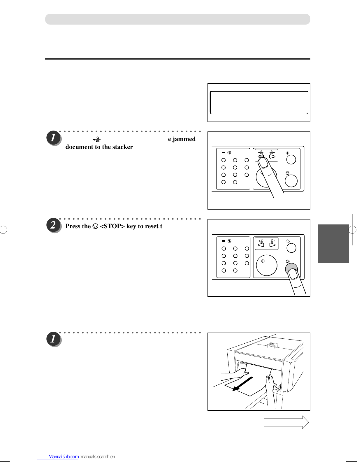
When “STACKER JAM” is Displayed
If a paper jam has occurred around stacker unit, “STACKER JAM” is displayed on the LCD panel and the
lamp blinks on the OK monitor.
Remove the jammed document with the following procedure.
○○○○○○○○○○○○○○○○○○○○○○○○○○○○○○○○
Press the <JOG> key and feed the jammed
document to the stacker tray side.
When a Paper Jam Has Occurred
––– J 6 –––
STACKER JAM
123
456
789
C
0
○○○○○○○○○○○○○○○○○○○○○○○○○○○○○○○○
Press the <STOP> key to reset the fault logic
and clear the message.
123
456
789
C
0
■ If the document cannot be removed with the procedure mentioned above
○○○○○○○○○○○○○○○○○○○○○○○○○○○○○○○○
Remove the jammed document.
25
Troubleshooting
Continue Page
•••
95
Page 97
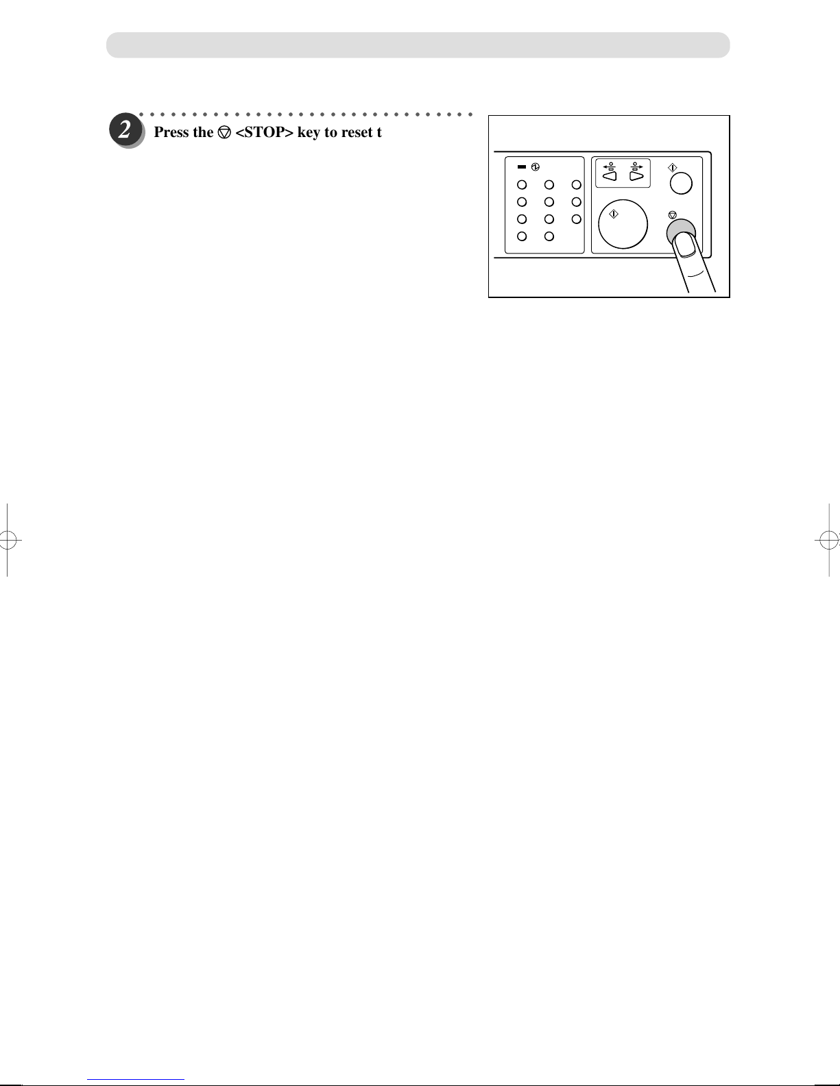
When a Paper Jam Has Occurred
○○○○○○○○○○○○○○○○○○○○○○○○○○○○○○○○
Press the <STOP> key to reset the fault logic
and clear the message.
123
456
789
C
0
96
Page 98
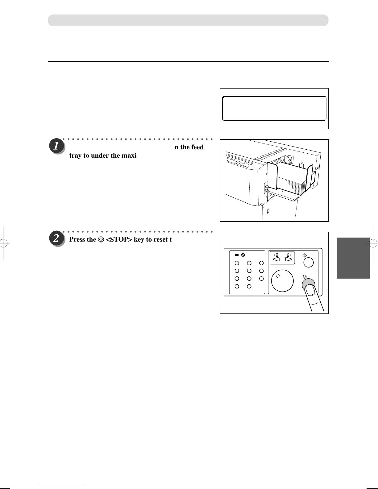
When a Paper Jam Has Occurred
When “OVER CAPACITY” is Displayed
If there are too many documents set on the feed tray, “OVER CAPACITY” will be displayed on the LCD
panel. Then the OK monitor light will flash.
Reduce the number of documents on the feed tray.
––– J 7 –––
OVER CAPACITY
○○○○○○○○○○○○○○○○○○○○○○○○○○○○○○○○
Reduce the number of documents on the feed
tray to under the maximum height permitted.
○○○○○○○○○○○○○○○○○○○○○○○○○○○○○○○○
Press the <STOP> key to reset the fault logic
and clear the message.
123
456
789
C
0
25
Troubleshooting
97
Page 99
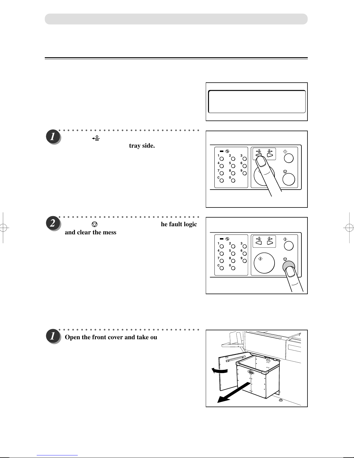
When a Paper Jam Has Occurred
When “REJECT AREA JAM” is Displayed
If a paper jam has occurred in the reject area, “REJECT AREA JAM” is displayed on the LCD panel and the
lamp blinks on the OK monitor.
Remove the jammed document with the following procedure.
––– J 8 –––
REJECT AREA JAM
○○○○○○○○○○○○○○○○○○○○○○○○○○○○○○○○
Press the <JOG> key and eject the jammed
document to the reject tray side.
123
456
789
C
0
○○○○○○○○○○○○○○○○○○○○○○○○○○○○○○○○
Press the <STOP> key to reset the fault logic
and clear the message.
123
456
789
C
0
■ If the document cannot be removed with the procedure mentioned above
○○○○○○○○○○○○○○○○○○○○○○○○○○○○○○○○
Open the front cover and take out the waste
box.
98
Page 100
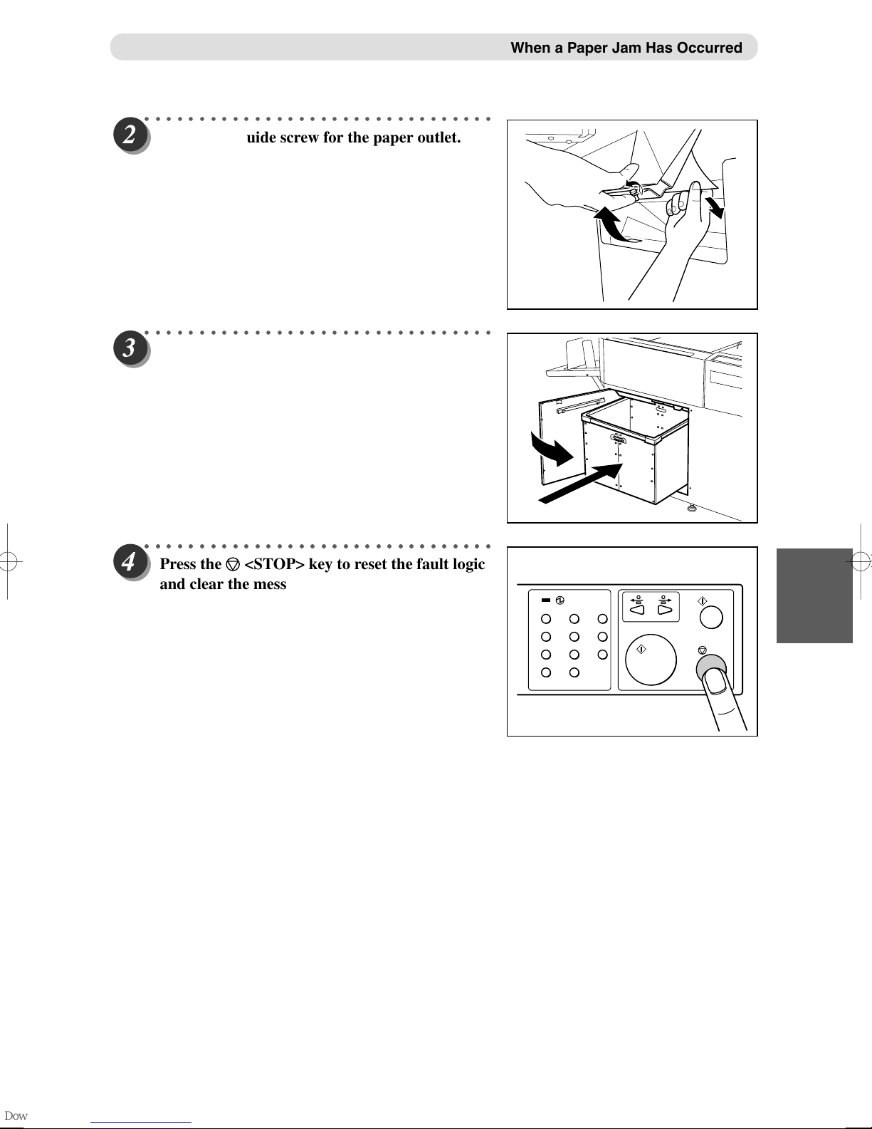
○○○○○○○○○○○○○○○○○○○○○○○○○○○○○○○○
Loosen the guide screw for the paper outlet. Lift
it forward and remove the paper jam.
○○○○○○○○○○○○○○○○○○○○○○○○○○○○○○○○
Put the waste box inside. Then close the front
cover.
When a Paper Jam Has Occurred
○○○○○○○○○○○○○○○○○○○○○○○○○○○○○○○○
○○○○○○○○○○○○○○○○○○○○○○○○○○○○○○○○
Press the <STOP> key to reset the fault logic
and clear the message.
123
456
789
C
0
25
Troubleshooting
99
 Loading...