

Page 1

SLITTER / CUTTER / CREASER
DC-616
Apr. 2014 Revision 0
DUPLO DC-616 S2-Y1540
Page 2

Page 3

Introduction
The cause of most accidents is failure to adhere to basic safety rules and observe
safety instructions. It is important to prevent potential causes of accidents from
occurring. In order to do so, read this manual carefully, and be sure to understand
all the safety instructions and correct inspection and servicing procedures that it
provides before beginning repair or servicing work.
Repairing or servicing the machine with insuffi cient knowledge about it could lead
to unforeseen accidents.
It is not possible to anticipate and describe in a manual such as this every possible
hazard that could arise in the course of repair and servicing. Therefore, besides
observing the safety instructions marked in this manual and on the machine’s
labels,
as necessary. When performing repair or service work not covered by this manual,
you should obtain safety guidance from an appropriately knowledgeable person.
Trademarks
• Microsoft, Windows, Windows NT, and Windows Vista are either registered trademarks or
trademarks of Microsoft Corporation in the United States and/or other countries.
All other company names and product names shown in this manual are trademarks or
registered trademarks of their respective companies.
service person should be safety-conscious and take other safety precautions
PLEASE NOTE
In the interests of upgrading our product, specifi cations and other data given in this manual are
subject to change without notice.
If the manual contains anything that you do not understand, contact the dealer for clarifi cation.
S2-Y1540
-0
1
Page 4

■ How to Use This Service Manual
• This service manual includes the structural and functional descriptions for the major areas
of DC-616, along with the descriptions of procedures for disassembly and assembly, design
standard and adjustment, maintenance and service requirements, and actions to be taken
in the case of malfunctions. These are the information as of April, 2014. The parts and
components used are subject to change for the quality and performance improvements, or
for safety reasons. In such cases, please note that certain part of the descriptions and/or
illustrations contained in this manual may differ from the actual product.
• The marking listed below accompanied by indicates the instruction of particular
importance for safety reasons. Never fail to comply with them.
●Safety instructions
WARNING
CAUTION
[Examples of Pictorial Symbols]
Indicates a high degree of potential danger. Failure to heed the warning
may lead to death or serious injury.
Indicates a medium degree of potential danger. Failure to heed the
caution may lead to injury or damage to property.
Δ symbol is to note that the instruction calls for close attention (including
danger and warning).
Specifi c hazard to be careful about is indicated in the drawing (e.g.
warning for electric shock in the case of illustration on the left).
A circle with a line through it indicates a prohibited action.
The particular act prohibited is indicated by a picture inside the circle.
(In the example shown here, the prohibited act is disassembly.)
● A black disc indicates an instruction, or sometimes a prohibited action.
The instruction itself is indicated by pictorial symbols drawn in white on
the disc. (In the example shown here, the instruction is “Remove the
plug from the outlet”.)
●For maintenance operation
IMPORTANT :
REFERENCE
S2-Y1540
2
-0
Introduces instructions for correct operation of the machine.
If these instructions are ignored, the machine may not be able to
operate at optimum performance or may break down.
Introduces information that is useful for operation and maintenance of
the machine, or information about the machine’s performance, etc.
Page 5

Safety Instructions
1. Cautions regarding the installation location
CAUTION
Installation environment
● Avoid installing the machine in places exposed to direct sunlight.
• Sunlight will cause the temperature in the machine’s interior to rise, possibly leading to
malfunction of the control system.
• Sunlight could cause misoperation of the sensors.
• The heat of direct sunlight could cause deformation of the machine’s plastic parts.
* Also avoid installation near to a ground glass window; light and heat penetrate such windows
although they are opaque.
Avoid installing the machine in places subject to high or low temperature or humidity.
●
• High or low temperature or humidity could cause the machine to operate abnormally.
Suitable temperature and humidity ranges are:
Ambient temperature : 10°C–30°C
Ambient humidity : 40%–70%
Optimum temperature and humidity : 20°C, 65%
If the machine is installed near to faucets, water heaters or humidifi ers, or in cool (sunless)
•
of a building or in the vicinity of water sources, the paper could absorb moisture and curl,
parts
leading
●
● Avoid installing the machine in poorly ventilated places.
● Avoid installing the machine in dusty places.
● The machine should not be tilting when it is used.
Install the machine so that it is level. (The machine should be level to within 5 mm in the front-rear
•
direction, and 5 mm in the lateral direction.)
● Do not install the machine on shaky, sloping or otherwise unstable surfaces.
• The machine could fall over on such surfaces, or fall off them, causing injury.
to misfeeds.
Avoid installing the machine in places with open fl ames, or where refl ected heat or other
hot air currents (from stoves, etc), or cold air currents from coolers, etc will strike
it directly.
S2-Y1540
-0
3
Page 6

2. Cautions for installation work
WARNING
● The machine’s power supply voltage and power consumption are given in the table
below. The machine's power supply voltage is indicated on the identifi cation plate on
machine; the machine must be connected to a power supply of the voltage indicated.
→ Otherwise, fi re or electric shock could result.
If the power supply voltage is unstable or if the power supply has insuffi cient capacity, the
machine may not operate normally. Make sure that the power supply has suffi cient capacity
for the system as whole, including optional equipment.
Power supply
Power consumption
Standby energy
● Use only the power cord that is provided with the accessories. Insert the power cord
plug fi rmly into the socket, so that proper electrical contact is made. Use of any other
power cord could result in imperfect grounding. If grounding is imperfect and
electrical leakage occurs, fi re or electric shock could result.
Install the machine close to its power supply. The outlet used should be exclusively for
●
the machine, and have no other equipment connected to it.
If an extension cord is necessary, it should have a ground terminal, and be of the following
ratings;
• For a 120 VAC model: 130 V, at least 15 A, length not exceeding 5 m
• For a 230 VAC model: 250 V, at least 8 A, length not exceeding 5 m
● Never tread on the power cord or pinch it between other objects, or accidents could
result.
115 VAC ±10%, 60Hz 230 VAC ±10%, 50/60 Hz
1.5 A,190 W 0.7 A,190 W
0.25 A, 26 W 0.22 A,26 W
CAUTION
● Install the machine in accordance with the Installation Manual supplied.
● Lock the casters after the machine is installed.
→ Otherwise, the machine could move or fall over, causing injury.
4
S2-Y1540
-0
Page 7

3. Cautions for maintenance, inspection and servicing
WARNING
● Always remove the power cord plug from the outlet before starting work.
→ Otherwise, your hands/fi ngers could get damaged beside electrical shock.
• However, the plug must be left connected to the outlet when performing function checks
individual motors, a given series of operations, or electrical circuits). When motors are
(of
operated
conditions and positions
or fi ngers into moving parts.
● The cutter unit, slitter unit, and perforation unit contain sharp tools (blades) which may
cause danger. Exercise great care when inspecting these units or replacing them or
their parts.
→ Otherwise, your hands/fi ngers could get caught and injured.
● Do not put your hands or fi ngers inside the machine while it is operating and while
you are pressing the JOG key.
→ Otherwise, your hands/fi ngers could get caught and injured.
In addition, when you remove paper clogged up or work on the machine, be very careful not
to roll up a tie and/or a necklace by the machine.
● Working clothes
• Wear clothing that enables you to work safely.
Work clothing should be close-fi tting.
alone in function checks, interlocks are deactivated, so be aware of the
of related equipment, and take great care not to put your hands
CAUTION
● Tools
• Use tools that are appropriate for the work.
S2-Y1540
-0
5
Page 8

■ Warning Labels
No. Part No. Name Q'ty
L1-T108*
1
L1-T111* (EU)
2
S2-T105* WARNING LABEL
M7-T303*
3
M7-T307* (EU)
4
S2-T115* WARNING LABEL
WARNING LABEL
WARNING LABEL
2
6
2
2
6
S2-Y1540
-0
Page 9

5
No. Part No. Name Q'ty
5
R7-T115* WARNING LABEL
1
S2-Y1540
-0
7
Page 10

No. Part No. Name Q'ty
L8-T109*
6
L8-T112* (EU)
WARNING LABEL
1
8
S2-Y1540
-0
Page 11

Introduction
Operation in General
Mechanism
Adjustment
Maintenance Checks
1
2
3
4
5
Troubleshooting
HELP Mode
Others
PC Controller
6
7
8
9
10
Page 12

Contents
Contents
Introduction
■ How to Use This Service Manual
Safety Instructions
■ Warning Labels
Chapter 1
1 Specifi cations
2 Part Names and Their Functions
3 Dimensions
Chapter 2
1 Paper Feed Section
2 Double Feed Detection Section (Option)
3 CCD Section
4 Margin Slitter Section
5 Center Slitter Section
6 Cutter Section
7 Creaser Section
8 Main Drive Section
9 Exit Tray
10
Exterior
11
Barcode
12
REG Mark
Chapter 3
1 Exterior of the Machine
2 Paper Feed Section
3 Double Feed Detection Section (Option)
4 CCD Section (Option)
5 Margin Slitter Section
6 Center Slitter Section
7 Cutter Section
8 Creaser Section
9 Main Drive Section
10
Electrical System Section
..........................................
.............
..............................
..................................
Introduction
....................................
.............
......................................
Operation in General
............................
.....................................
..........................
..........................
...................................
.................................
.............................
..........................................
..........................................
..........................................
.......................................
Mechanism
........................
............................
..........................
..........................
..........................
...................................
.................................
.............................
....................
...
...
12
14
20
22
26
27
28
30
33
35
39
40
41
43
46
51
56
67
68
70
76
83
85
90
96
1
2
3
6
Chapter 5
1 Guaranteeing Maintenance Cycle
2 Cleaning and Oiling
3 Periodic Maintenance Check List
4 Recommended Parts List
Chapter 6
1 Troubleshooting
2 Conditions for the Error Detection
3
Major Cause and Preventive Action for the Paper Jam
4 Slitter Blade Intersection Correction
Chapter 7
1 HELP Mode List
2 Accessing the HELP Mode
3 Finishing the HELP Mode
4 Setting the Other HELP Mode No.
5 Accessing the Service Person JOB
6 HELP Mode Description
Chapter 8
1
Position and Function of Electronic Parts
2 Service Person JOBs
3 Overall Wiring Layout
Chapter 9
1 Main Menu of PC Controller
2 Maintenance Menu
3 Data Folder
4 Maintenance
5 Confi rming the Version
Maintenance Checks
...........................
Troubleshooting
................................
HELP Mode
...............................
Others
........................
........................
PC Controller
...........................
....................................
...................................
..........
...........
....................
.........
.......
..................
...................
.........
.......
.....................
..
................
.......................
110
110
111
112
116
122
.
124
125
128
129
129
129
129
130
168
178
182
186
188
191
192
202
Chapter 4
1 Exterior of the Machine
2 Paper Feed Section
3 CCD Section
4 Margin Slitter Section
5 Center Slitter Section
6 Cutter Section
7 Creaser Section
8 Main Drive Section
10
Adjustment
W5-Y1030
..........................
...................................
........................
........................
.................................
...............................
...........................
-0
......................
100
101
102
103
104
105
106
108
Page 13

1
Chapter 1
Introduction
1 Specifi cations
2 Part Names and Their Functions
1. Appearance
2. Ejection Side
3. Appearance (Ejection side)
4. Inside
5. Control Panel
6. LCD Panel
3 Dimensions
..................................
.................................
................................
........................................
...............................
..................................
.....................................
...........
..............
12
14
14
15
16
17
18
19
20
Page 14

Chapter 1 1 Specifi cations
1 Specifi cations
Model name DC-616
Product type Slitter/Cutter/Creaser Floor stand model
Feeding method Belt suction
Infeed document size Width: 210–320 mm
Length: 210–670 mm*
* The standard feed tray takes up to 460 mm. For longer sheet, the
optional long paper tray is available.
Minimum fi nishing size Width: 48 mm (1.89 in)
Length: 50 mm (1.97 in)*
The distance between the lead edge of the last card and the trail edge
of the parent sheet should be 67 mm or more.
Document type Uncoated, coated, laminated*
* Laminated document is not included in the specifi cations of the
perforation unit.)
Document weight 110 gsm–350 gsm
Paper curl Within 5 mm
Feeder capacity 100 mm
Speed 10 ppm (A4 SEF, 2 cuts, 1 crease)
Number of slits Max 6 slits per document (2 margin slitters and 4 center slitters)
Margin slit spec 3.2–55.0 mm from document side edges
Gutter slit width 5.0–15.0 mm
Gutter slits wider than above are exited onto the exit tray.
Gutter defl ector Max 2 gutter slits can be defl ected.
Number of cuts
Cut position spec Lead edge: min. 3.0 mm
Number of creases Max 20 per document
Crease depth adjustment 3 steps (from control panel)
Tolerance +/-0.3 mm from programmed positions
Stacker capacity 100 mm (with card stacker: 40 mm)
Control panel 64×128 dots LCD
LCD languages Japanese, English, French, German, Italian, Spanish, Polish, Russian
Software update DDL-01, DDL-02
Perforation unit Operator replaceable unit
Perforation position Minimum distance from the card side edge: 5 mm
Perforation tool spec Cut: 0.84 mm Tie: 0.84 mm
Max 25 per document
Gutter cut: min. 3.0 mm
Trail edge: min. 5.0 mm
(+/-0.4 mm with business cards)
When creasing, it may fl uctuate depending on the number of creases
and their depths.
Max 2 perforations parallel to the feeding direction
Manual positioning
Minimum distance between 2 perforations: 48 mm
12
S2-Y1540
-0
Page 15

Chapter 1 1 Specifi cations
Model name DC-616
Functions 80 job memory
Test feed
Skew adjustment
Slitter guide
Auto cut
Apply shrinkage
Adjust all
Cleaning mode
Automatic job setup by reading barcode (CCD is optional on “115V”
and “230V Asia Oceania” models.)
Image shift compensation by reading REG mark (CCD is optional on
“115V” and “230V Asia Oceania” models.)
Options Air knife (optional on “230V Asia Oceania” model)
Double feed detection (optional on “115V” and “230V Asia Oceania”
models)
CCD (standard on “115V PRO” and “230V EMEA” models)
Card stacker (optional on “230V Asia Oceania” model)
Perforation unit (optional on “115V” and “230V Asia Oceania” models)
Long paper tray
PC am mount (standard on “115V PRO” model)
PC controller software (standard on “115V PRO” model)
USB (B TYPE CONNECTOR)
Compatible OS:
Windows XP Professional/Home edition (x86 32bit only)
Windows Vista Ultimate/Business/Home basic/Home premium
Windows 7 Ultimate/Professional/Home premium
Windows 8 Professional/Enterprise
Power supply 115 VAC, 60 Hz 230 VAC, 50/60 Hz
Power consumption 115 V: current consumption 1.5 A (standby: 0.25 A)
power consumption 190 W (standby: 26 W)
230 V: current consumption 0.7 A (standby: 0.22 A)
power consumption 190 W (standby: 26 W)
Dimensions In use: 1610 (W) × 625 (D) × 1060 (H) mm
In use with max paper: 2025 (W) × 625 (D) × 1060 (H) mm
Stored: 975 (W) × 625 (D) × 1060 (H) mm
Packed: 1140 (W) × 770 (D) × 1360 (H) mm
Machine weight 115 V: 145 kg (Gross weight: 178 kg)
115 V PRO: 155 kg (Gross weight: 188 kg)
230 V EMEA: 150 kg (Gross weight: 183 kg)
230 V Asia Oceania: 140 kg (Gross weight: 173 kg)
Operating temperature 10–30 degrees (Celsius) (50-80 degrees (F))
Operating humidity 40%–70% RH (No condensation)
Storing temperature 5–35 degrees (Celsius)
Storing humidity 20%–70% RH (No condensation, No exposure to salt)
Operating altitude Max 1000 m ALT
Safety standard UL, CE, VCCI
1
The specifi cations are subject to change without prior notice.
Paper Curl
Due to the automated slitter function, the paper path of the DC-616 is sensitive to paper curl.
If paper curl is causing paper jams, the following are suggestions for remedying the problem:
1. Adjust the printing devices de-curler (if available).
2. Manually de-curl the stock before loading in the fe tray.
3. Turn the paper over (reprogramming the job may be necessary).
4. Use different paper stock.
S2-Y1540
-0
13
Page 16

Chapter 1 2 Part Names and Their Functions
2 Part Names and Their Functions
1. Appearance
1
7
6
2
5
3
4
No. Name Function
1
Control panel Displays operations and status.
2 Exit tray Receives the fi nished products.
3 Waste box Receives pieces of waste paper.
4 Front cover Open this to remove the waste box.
5 Feed tray Original document is placed here.
6 Scale Measures the cut and slit position, and the fi nished product.
7
Top cover Open this to remove paper jam from inside of the machine.
14
S2-Y1540
-0
Page 17

2. Appearance (Feed Side)
1
2
Chapter 1 2 Part Names and Their Functions
1
4
3
No. Name Function
1 Airfl ow adjustment knob Adjusts airfl ow level.
2 Separator adjustment
knob
3 Skew adjustment knob Adjusts the document skew.
4 Level adjustment knob Adjusts the elevator height.
Adjusts the distance between the separator and conveyance
belt.
S2-Y1540
-0
15
Page 18

Chapter 1 2 Part Names and Their Functions
3. Appearance (Ejection side)
2
1
3
6
4
5
No. Name Function
1 Perforation unit Perforates parallel to the document feed direction.
2 Side guide Receives the processed documents.
3 Back guide Receives the processed documents.
4 USB terminal Used for the connection to your computer on PC Controller using.
5 AC inlet Connect the power cord here.
6 Power switch Press to switch the power on and off.
16
S2-Y1540
-0
Page 19

4. Inside
Chapter 1 2 Part Names and Their Functions
8
7
6
5
4
3
2
1
1
5
No. Name Function
1 Double feed detection
section
2 CCD section Reads out REG Mark/Barcode. (Option)
3 Slitter module 1,2 Cuts side margins parallel to the document feed direction
4 Slitter module 3,4
5 Slitter module 5,6
6 Gutter defl ector Drops the margin cut off by the slitters into the waste box.
7 Cutter module Cuts perpendicularly to the document feed direction.
8 Creaser module Creases perpendicularly to the document feed direction.
Detects double feed by the ultrasonic sensor. (Option)
Cuts parallel to the document feed direction
4
3
.
.
S2-Y1540
-0
17
Page 20

Chapter 1 2 Part Names and Their Functions
5. Control Panel
1
32
No. Name Function
1 LCD panel
2 F key Switches to function selecting screen.
3 RETURN key Switches to the previous screen.
CURSOR (Left/
4
Right) key
CURSOR (Up/
5
Down) key
6 SET key Press to set selection/entry.
JOG (Forward/
7
Backward) key
8 TEST key
9 START key
10 STOP key
4
5
Displays the status of the machine.
Displays the message when an error or paper jam occurs.
Press to move the cursor to the left or right.
Press to the cursor in a lower or an upper direction.
Press to eject the document from the machine when paper jam
occurred.
One (sheet) document is processed to test to the current JOB
details. When the card stacker is installed, if you press and hold the
TEST key for guide adjustment, the processed document temporarily
stops. Then, when you press the START key or the TEST key, the
processed document is ejected.
Press to start processing documents. The START key light turns
green when when the machine is ready to process the document in
this machine. The machine is inactive when the light is red. In this
case, the machine may be running or having an error.
Press to return the current screen to the main screen or to stop
processing
6
7
9
8
10
1
1
3
No. Name Function
1 NUMERIC key Press to enter JOB/values during manual programming.
2 SET key Press to set selection/entry.
3 CLEAR key Press to clear the count. Press to cancel manual programming.
18
S2-Y1540
-0
2
Page 21

6. LCD Panel
Chapter 1 2 Part Names and Their Functions
● Standby screen
2
1
3
4
No. Name Function
1 JOB No. Displays the JOB number currently selected.
2 JOB Name Displays the JOB name currently selected.
3 Counter
Function setting
AC: Auto cut
REG: REG mark
4
BC: BARCODE
%
Displays the number of document sheets processed with the JOB
currently set.
AC is displayed when “Auto cut” is enabled.
REG is displayed when “REG mark reading” is enabled.
BC is displayed when “Barcode reading” is enabled.
% is displayed when “Apply shrinkage” is enabled.
is displayed when “Adjust all” is enabled.
1
is displayed when the PC Controller is online.
● “Select menu” screen
Select menu Select menu
1
2
3
No. Name Function
1 Retrieve JOB Retrieves saved JOB.
2 Enter JOB Enters and changes JOB.
3 Setting Changes functions of the machine.
4 Cleaning mode Retrieves Cleaning mode to clean conveyance belt / conveyance
5 Return Returns to standby screen.
Retrieve JOB
Enter JOB
Setting
roller.
3
Setting
4
Cleaning mode
5
Return
S2-Y1540
-0
19
Page 22

Chapter 1 3 Dimensions
3 Dimensions
Unit: mm
20
S2-Y1540
-0
Page 23

Chapter 2
Operation in General
2
1 Paper Feed Section
1. Description
2. Operation
3. Operation of Each Part
2 Double Feed Detection Section (Option)
1. Description
2. Operation
3. Operation of Each Part
3 CCD Section
1. Description
2. Operation
3. Operation of Each Part
4 Margin Slitter Section
1. Description
2. Operation
3. Slitter Blade
4. Operation of Each Part
5 Center Slitter Section
1. Description
2. Operation
3. Slitter Blade
4. Operation of Each Part
6 Cutter Section
1. Description
2. Operation
3. Operation of Each Part
7 Creaser Section
1. Description
2. Operation
3. Operation of Each Part
8 Main Drive Section
1. Description
9 Exit Tray
1. Description
10
Exterior
1. Description
2. Operation
3. Operation of Each Part
11
Barcode
1. Description
12
REG Mark
1. Description
....................................
....................................
...................................
....................................
....................................
....................................
....................................
....................................
.........................................
.........................................
....................................
........................................
.....................................
...........................
..................................
...................
..................................
...................
..................................
...................
.........................
..................................
.................................
...................
.........................
..................................
.................................
...................
..................................
..................................
...................
...............................
..................................
...................
............................
..................................
..................................
..................................
...................
..................................
..................................
22
22
22
22
..
26
26
26
26
27
27
27
27
28
28
28
28
28
30
30
30
30
30
33
33
33
33
35
35
35
36
39
39
40
40
41
41
41
41
43
43
46
46
Page 24

Chapter 2 1 Paper Feed Section
1 Paper Feed Section
1. Description
Paper feed section feeds the paper into the machine
after separating each sheet of paper by air knife.
This is done through the operation of the air suction
mechanism and the air blow duct mechanism.
2. Operation
Air blow duct mechanism blows the compressed
air to the paper from the front side to create some
gap between the papers. The separated paper is
transferred when the shutter solenoid and the feed
motor provided in the air suction mechanism are
turned ON.
3. Operation of Each Part
1. Level Sensor
<Operation>
• Detect the top of the paper on the feed tray
When the feed tray rises to the extent that the
actuator is lifted up by the paper, the sensor comes
to the “light blocked” state.
Once the topmost sheet of paper is detected, the
rising motion of the feed tray is stopped.
• Detect the low level of paper
The actuator comes down as the paper level gets
low until the sensor comes to the “light through”
state. Once the sensor comes to the “light through”
state, the feed tray rises until the sensor comes
to the “light blocked” state. “E02” (elevator error)
appears on the display if the topmost paper sensor
does not switch to the “light blocked” state within 10
seconds after the transmission of feed tray go-up
command.
22
S2-Y1540
-0
Page 25

<Circuit diagram>
Chapter 2 1 Paper Feed Section
Level sensor
Red Red
1
2
3
Yellow
Blue
6
7
8
Yellow
Blue
2. Elevator Upper Limit Switch
<Operation>
If the topmost sheet of paper cannot be detected, and
the feed tray continues to go up, the air suction unit
is pulled away from the elevator upper limit switch to
come to the “OFF” state.
The elevator upper limit switch stops the machine
operation immediately once it comes to the “OFF”
state.
CN2-10
11
12
Main PCB unit
5V
5V
2
Light not transmitted: 5V
Light transmitted: 0V
3. Elevator Motor
<Operation>
Elevator motor rotation lets the feed tray move up and
down.
<Circuit diagram>
Elevator upper limit switch
Brown
Brown
2
1
Elevator motor
BrownBrown
1
M
Black
2
Brown
Black
Drive PCB unit
CN5-2
1
S2-Y1540
-0
23
Page 26

Chapter 2 1 Paper Feed Section
4. Elevator Lower Switch
<Operation>
As the feed tray goes up, the angle is pulled away
from the elevator lower limit switch to come to the
“OFF” state. As the feed tray goes down to reach the
lower limit, the angle pushes the switch actuator to
trigger the “ON” state. “E02” (elevator error) appears
on the display if the angle does not push the elevator
lower limit switch actuator within 30 seconds after the
transmission of the feed tray go-down command.
<Circuit diagram>
Elevator lower switch
Purple
1
Purple
2
Purple
4
Purple
5
5. Perforation unit Sensor
<Operation>
Normally the feed tray goes up and down
automatically. However, it may be lowered by the
elevator down switch as required, including the case
of paper jam.
Main PCB unit
5V
CN3-19
02
ON : 0V
OFF : 5V
<Circuit diagram>
Elevator down switch
24
S2-Y1540
-0
Light green Light green
Light greenLight green
Main PCB unit
5V
CN2-25
26
ON : 0V
OFF : 5V
Page 27

6. Shutter Solenoid
<Operation>
The suction solenoid is turned ON as the level sensor
is turned ON and the paper feed is ready.
Then, the valve opens to suck up the paper.
The valve is closed by the timer after the transferred
paper passes through the PPS2.
<Circuit diagram>
Chapter 2 1 Paper Feed Section
2
Shutter solenoid
Red
1
Yellow
2
Red
Yellow
7. PPS1
<Operation>
While the light goes through at PPS1, LED on the
control panel lights up in red. “NO PAPER” appears
on the display as the start key is pressed. While the
light is blocked at the PPS1, the start key lights up in
green.
* Wipe off the dirt or contamination, if any, on the
PPS sensor with a rag.
Drive PCB unit
24V
CN2-7
8
<Circuit diagram>
Paper sensor
Emitting
Receiving
Main PCB unit
1
3
1
2
3
Red Red
1
Orange Orange
2
Red Red
Gray
Blue
1
2
3
Gray
Blue
CN4-1
5V
2
5V
3
5V
4
5
Light not transmitted: 5V
Light transmitted: 0V
S2-Y1540
-0
25
Page 28

Chapter 2 2 Double-Feed Detection Section (Option)
2 Double Feed Detection Section (Option)
1. Description
The double feed detection sensor is provided at the
ejection side of feed belt.
An ultrasonic sensor is used, and no adjustment for
fi tting it to the particular type of paper, and no input of
the paper thickness are required.
2. Operation
Whenever the ultrasonic sensor detects double feed,
the machine stops the operation.
3. Operation of Each Part
1. Double Feed Sensor
<Operation>
Whenever the ultrasonic sensor detects double feed,
the machine stops the operation. The double feed is
detected not by the paper thickness, but by the number
of sheets.
Receiving
Receiving
<Circuit diagram>
Double feed sensor
Receiving
Main PCB unit
Red
White
CN9-2 4
White Blue
12
Receive PCB
TransmittingTransmitting
24V Power supply unit
21
42
Brown
Blue
V +
V -
26
Transmitting
S2-Y1540
-0
Red
Yellow
21
42
Transmit PCB
Page 29

3 CCD Section
1. Description
This section reads the barcode and REG mark by
CCD.
2. Operation
On the JOB using REG mark or barcode, PPS2 works
to assure the correct CCD reading by temporarily
stopping the paper run at the place of PPS2 and slows
it. The paper conveyance speed will be accelerated
after the CCD reading.
Chapter 2 3 CCD Section
2
3. Operation of Each Part
1. PPS2
<Operation>
•
PPS detects the presence or non-presence of paper
by the “light-through” or the “light-bloced” state of the
PPS photo-receiving sensor by means of
from the PPS photo-emitting sensor.
• In the operation without REG mark or barcode,
PPS2 detects the timing of passing paper.
<Circuit diagram>
PPS2
Red
Orange
Red Red
Gray
Blue Blue
Emitting
Receiving
1
3
1
2
3
receiving
1
2
1
2
3
Red
Orange
Gray
CN4-6
7
8
9
10
5V
5V
Main PCB unit
5V
Light not transmitted: 5V
Light transmitted: 0V
S2-Y1540
-0
27
Page 30

Chapter 2 4 Margin Slitter Section
4 Margin Slitter Section
1. Description
The margin slitter is provided (slitter 1, 2) on both
sides to cut the paper along the traveling direction
by means of the rotary blades. The cut-off margin is
dropped into the waste box.
2. Operation
The lead screw is turned by means of the stepping
motor to cause the margin slitter to move from the
home position by the specifi ed amount of pulse.
3. Slitter Blade
The slitter blades are constructed so that the lower
blade of the slitter is tilted relative to the paper feed
direction. This makes the upper and lower slitter
blades contact at only one point to maintain the clean
cut even after the slitter blade has worn out.
4. Operation of Each Part
1. Margin Slitter Home Position Sensor
<Operation>
Margin slitter HP sensor detects the home position
of the margin slitter by the photo-micro sensor, and
controls the margin slitter position based on the
amount of pulse from the home position.
28
S2-Y1540
-0
Page 31

<Circuit diagram>
Slitter HP1 sensor
Chapter 2 4 Margin Slitter Section
Main PCB unit
Blue
1
White
2
Red
3
2
3
1
Slitter HP2 sensor
Blue
1
Pink
2
Red
3
2
3
1
2. Margin Jam Sensor
<Operation>
The system stops the machine when a sensor cannot
detect light for more than fi xed period of time during
machine runs.
CN2-3
CN3-3
5V
2
1
5V
2
5V
2
1
5V
Light not transmitted: 5V
Light transmitted: 0V
<Circuit diagram>
Margin jam sensor
Receiving
Emitting
Main PCB unit
1
2
3
4
1
3
Black
White
Orange
Red
Black
Orange
4
3
2
1
2
1
CN4-27
26
25
24
23
22
5V
5V
Light not transmitted: 5V
Light transmitted: 0V
S2-Y1540
-0
29
Page 32

Chapter 2 5 Center Slitter Section
5 Center Slitter Section
1. Description
Two pairs of center slitters (slitter 3–6) are provided to
cut the paper in the traveling direction by mean of the
rotary blades arranged vertically side by side.
2. Operation
The lead screw is turned by means of the stepping
motor to cause the center slitters to move from the home
position by the specifi ed amount of pulse.
3. Slitter Blade
The slitter blades are constructed so that the lower blade
of the slitter is tilted relative to the paper feed direction.
This makes the upper and lower slitter blades contact at
only one point to maintain the clean cut even after the
slitter blade has worn out.
4. Operation of Each Part
1. Center Slitter Home Position Sensor
<Operation>
Center slitter HP sensor detects the home position
of the center slitter by the photo-micro sensor, and
controls the center slitter position based on the
amount of pulse from the home position.
30
S2-Y1540
-0
Page 33

<Circuit diagram>
Chapter 2 5 Center Slitter Section
Main PCB unit
Slitter HP3 sensor
1
2
3
Slitter HP4 sensor
1
2
3
Slitter HP5 sensor
1
2
3
Purple
Blue
Red
Gray
Blue
Red
Yellow
Blue
Red
CN2-5
6
4
CN3-5
6
4
CN2-8
9
7
5V
2
5V
Light not transmitted: 5V
Light transmitted: 0V
5V
5V
Light not transmitted: 5V
Light transmitted: 0V
5V
5V
Light not transmitted: 5V
Light transmitted: 0V
Slitter HP6 sensor
1
2
3
Yellow
Blue
Red
CN3-8
9
7
5V
5V
Light not transmitted: 5V
Light transmitted: 0V
S2-Y1540
-0
31
Page 34

Chapter 2 5 Center Slitter Section
2. PPS3
<Operation>
•
PPS detects the presence or non-presence of paper
by the “light-through” or the “light-bloced” state of the
PPS photo-receiving sensor by means of
from the PPS photo-emitting sensor.
receiving
• PPS3 detects the passing paper and paper jam in
the slitter area.
<Circuit diagram>
PPS3
Receiving
Emitting
Red
1
Orange
3
Red
1
Gray
2
Blue
3
1
2
1
2
3
Red
Orange
Red
Gray
Blue
3. Gutter ON/OFF Sensor
<Operation>
The gutter ON/OFF sensor
detects the gutter guide
position by the photo sensor, and in case the gutter is
not needed, “Gutter Released” is displayed.
CN4-11
12
13
14
15
Main PCB unit
5V
5V
5V
Light not transmitted: 5V
Light transmitted: 0V
<Circuit diagram>
Gutter ON/OFF sensor
32
S2-Y1540
-0
Receiving
Emitting
Main PCB unit
Black
1
White
2
Orange
3
Red
4
Black
1
Orange
3
4
3
2
1
2
1
CN4-21
20
19
18
17
16
5V
5V
Light not transmitted: 5V
Light transmitted: 0V
Page 35

6 Cutter Section
1. Description
The “Guillotine type” cutter module is provided in
which the lower blade is fi xed while the upper blade
moves up and down to cut the paper perpendicularly
to the traveling direction.
2. Operation
The rotating motion of the DC motor is transformed
into the reciprocating motion of the upper blade by
means of the eccentric shaft.
A sensor is provided at the top dead center of the
blade stroke, which works to apply the brake on the
blade movement at every reciprocating cycle to make
it stop.
Chapter 2 6 Cutter Section
2
3. Operation of Each Part
1. Cutter Home Position Sensor
<Operation>
Cutter HP sensor detects the blade positions
by sensing the light-blocking plate linked to the
movement of rotary blade by means of the photomicro sensor.
<Circuit diagram>
Cutter HP sensor
Blue Blue
1
Yellow Yellow
2
Red
3
3
2
1
Red
CN2-18
17
16
Main PCB unit
5V
5V
Light not transmitted: 5V
Light transmitted: 0V
S2-Y1540
-0
33
Page 36

Chapter 2 6 Cutter Section
2. Cutter Motor
<Operation>
Cutter motor controls the upper blade up and down
operation.
<Circuit diagram>
Cutter motor
M
Red
Black
Red
1
Black
2
CN6-3
Drive PCB unit
4
34
S2-Y1540
-0
Page 37

7 Creaser Section
1. Description
Creaser module contains the lower blade having
a concave (recessed) section and the upper blade
having a convex (projected) section. The creaser
unit works to crease the paper perpendicularly to its
traveling direction.
2. Operation
The sensor plate provided coaxially with the cam
detects the top dead center of the upper blade to
control the DC motor. The lower blade also can
move up and down by a cam. The height of the
lower blade is set by the DC motor with an encoder,
and is specifi ed relative to the lower blade’s bottom
dead center at which the sensor plate is provided.
The crease depth is determined in this way.
Chapter 2 7 Creaser Section
2
S2-Y1540
-0
35
Page 38

Chapter 2 7 Creaser Section
3. Operation of Each Part
1. Crease Lower Blade Home Position Sensor
<Operation>
This sensor detects the crease home position by
sensing the sensor plate attached to the eccentric
shaft by means of the photo-micro sensor.
<Circuit diagram>
CREASE LOW HP sensor
1
2
3
Red
Light green
Blue
4
5
6
2. Crease Home Position Sensor
<Operation>
This sensor detects the crease home position by
sensing the sensor plate attached to the eccentric
shaft by means of the photo-micro sensor.
<Circuit diagram>
CN3-13
14
15
Main PCB unit
5V
5V
Light not transmitted: 5V
Light transmitted: 0V
CREASE HP sensor
Main PCB unit
5V
Red
1
White
2
Blue
3
1
2
3
CN3-10
11
12
Light not transmitted: 5V
Light transmitted: 0V
5V
36
S2-Y1540
-0
Page 39

3. Creaser Lower Blade Encoder Sensor
<Operation>
Creaser lower blade encoder sensor adjusts the crease
depth in three levels from the lower limit position by
reading out the encoder attached to the crease depth
adjustment motor by means of the photo-micro sensor.
<Circuit diagram>
Chapter 2 7 Creaser Section
2
CREASE ENCODER
1
2
3
Red
Purple
Blue
7
8
9
4. PPS4
<Operation>
The
light from the PPS photo-emitting PCB is
received by the PPS photo-detecting PCB. The
presence or non-presence of the paper is determined
by the
receiving amount.
PPS4 detects the passing paper and paper jam in the
cutter and crease areas.
CN3-16
17
18
Main PCB unit
5V
5V
Light not transmitted: 5V
Light transmitted: 0V
<Circuit diagram>
PPS4
1
2
3
1
3
Red
Gray
Blue
Red
Orange
Main PCB unit
1
2
3
1
2
CN4-13
14
15
11
12
5V
5V
5V
Light not transmitted: 5V
Light transmitted: 0V
S2-Y1540
-0
37
Page 40

Chapter 2 7 Creaser Section
5. Crease Motor
<Operation>
Crease motor controls the crease upper blade up and
down operation.
<Circuit diagram>
CREASE MOTOR
Red
Red
1
M
Black
6. Crease Low Motor
<Operation>
Crease low motor rotates the encoder attached in the
crease lower motor to adjust the crease depth in three
steps.
<Circuit diagram>
CREASE LOW MOTOR
Brown Brown
Black
2
1
M
Black Black
2
CN6-1
CN5-4
Drive PCB unit
2
Drive PCB unit
5
7. Perforation Unit Sensor
<Operation>
Perforation unit sensor detects whether the perforation unit is installed or not.
<Circuit diagram>
Perforation Unit Sensor
5V
CN2-19
23
24
38
S2-Y1540
-0
1
2
3
Red
White
Blue
1
2
3
Main PCB unit
5V
Light not transmitted: 5V
Light transmitted: 0V
Page 41

8 Main Drive Section
1. Description
Stepping motors are used for activating components
related to the paper cutting dimensions, paper
transfer, each slitter, transversal position of the gutter.
The movement of other DC motors are also controlled
by the encoder attached to the motor as required.
Chapter 2 8 Main Drive Section
2
S2-Y1540
-0
39
Page 42

Chapter 2 9 Exit Tray
9 Exit Tray
1. Description
Exit tray is for receiving the fi nished paper discharged
from the machine.
The exit tray can be set at four different heights.
Normally the tray is set at the middle height position.
Upper position is to install the
Lower position is for the papers with strong static
electricity.
Card Stacker.
40
S2-Y1540
-0
Page 43

10
Exterior
1. Description
Exterior section detects the opening and closing of
each cover. The machine stops immediately when the
cover is opened during operations.
2. Operation
The machine stops immediately when opening of the
cover is detected during operations.
3. Operation of Each Part
1. Top Cover Interlock Switch
<Operation>
Top cover interlock switch detects the opening
and closing of the top cover. The machine stops
immediately when the cover is opened during
operations.
When the cover is closed, the cover presses the
switch.
When the cover is opened, the cover is off the switch.
Chapter 2 10 Exterior
2
2. Front Cover Interlock Switch
<Operation>
Front cover interlock switch detects the opening
and closing of the front cover. The machine stops
immediately when the cover is opened during
operations.
When the cover is closed, the cover presses the
switch.
When the cover is opened, the cover is off the switch.
S2-Y1540
-0
41
Page 44

Chapter 2 10 Exterior
<Circuit diagram>
Front cover interlock switch
Brown
Brown Brown
Rear cover interlock switch
Top cover interlock switch
Brown
Brown
Brown
Brown
Brown
CN7-2
3
1
2
CN14-1
2
Main PCB unit
Relay
Drive PCB unit
42
S2-Y1540
-0
Page 45

11
Barcode
1. Description
By adding barcode which indicates job number on
each document, DC-616 automatically set up the
machine and start the job. Operator can press the
START key and leave. Even if multiple types of jobs
are loaded on the feed tray at one time, DC-616
recognizes barcode on documents also with the builtin CCD reading and automatically switch setup and
fi nish the jobs.
To use this function, each documents must have
BARCODE printed on them. Please refer to following
instructions for specifi cations and position of
BARCODE.
1. Specifi cations
Barcode type : CODE-39
Start and Stop code : Required
Minimum resolving power : 0.254 mm
Thin bar: Thick bar : 1: 2.5
Bar height : 4 mm or more
Chapter 2 11 Barcode
Paper feed direction
2
Use barcode generator function equipped on your
software application or use barcode generator
software.
REFERENCE
Barcode may not be read even it is within the
specifi cations depending on the print quality of printer
and document type. If this is the case, enlarging the
barcode may enable it to be read.
S2-Y1540
-0
43
Page 46

Chapter 2 11 Barcode
2. Position of barcode
Paper feed direction: The whole BARCODE should be within
3 to 20 mm from the lead edge.
Paper width direction: The whole BARCODE should be
within 25 to 60 mm from the right edge.
* Here is the example barcode: CODE39 (*21*).
(See below)
60 mm or less
35 mm
3 mm
Barcode
Position Range
Barcode
1. is the start code designator for CODE-39. (*)
2. is the 10’s digit data of the JOB number.
(Example: When the JOB number is 21, the data is “2”.)
3. is the 1’s digit data of the JOB number.
(Example: When the JOB number is 21, the data is “1”.)
4. is stop code of CODE-39. (*)
25 mm
20 mm
Paper feed direction
1 2 3 4
44
S2-Y1540
-0
Page 47

3. Position of check digit
Modulus43 is the calculational procedure of check
digit specifi ed for CODE39. Each of 43 character types
available to CODE39 are allocated each Numeric
Number to be calculated after converting them to the
numeric number. Here is the example calculation of
check digit (*21*) in CODE39.
1. is the start code designator for CODE-39. (*)
2. is the 10’s digit data of the JOB number.
(Example: When the JOB number is 21, the data is 2”.)
3. is the 1’s digit data of the JOB number.
(Example: When the JOB number is 21, the data is 1”.)
4. is stop code of CODE-39. (*)
4. Calculation procedure of check digit
1. Convert all the data characters to the numeric number
referring the table 1.
(Except start '*' and stop '*' code.) 21→2,1
Chapter 2 11 Barcode
1 2 3 4 5
2
2. Add the each converted number.
2 + 1 = 3
3. Divide the number of calculated in step 2 by 43, and
fi nd out the remainder.
3÷43 = Remainder 3
4. Convert the remainder 3 calculated in step 3 to the
character referring the table 1.
3→3
Therefore, the check digit is 3, and the data will be 213*'.
Table 1 Modulus43 Check Digit Calculation List
Character 0 1 2 3 456789ABCDE
Value 0 1 2 3 4567891011121314
Character F G H I J K L M N O P Q R S T
Value 15 16 17 18 19 20 21 22 23 24 25 26 27 28 29
Character U V W X Y Z -
Value 30 31 32 33 34 35 36 37 38 39 40 41 42
•
$/+%
S2-Y1540
-0
45
Page 48

Chapter 2 12 REG Mark
12
REG Mark
1. Description
DC-616 automatically compensate for image drift, one
of the common problems on digital printers. It detects
the image drift caused on each page by reading REG
mark with built-in CCD and adjust the cut/slit/crease
position accordingly.
To use this function, each documents must have
REG mark printed on them. Please refer to following
instructions for specifi cations and position of REG
mark.
Lead mark
Correct for
image drift
in this direction
Paper feed direction
Side mark
Correct for image drift
in this direction
1. Specifi cations
REG mark consists of two straight and perpendicular
lines.
Line length: 5 mm or more / each
Line thickness: 0.4 mm or more / each
Use pen tool etc. of your software application to draw
2 straight and perpendicular lines.
2. Position
Paper feed direction: The whole REG mark should be
within 3 to 20 mm from the lead
edge.
Paper width direction: The whole REG mark should be
within 3 to 20 mm from the right
edge.
REFERENCE
Right fi gure shows optimum position of REG mark.
20 mm
5 mm or more
0.4 mm or more
REG Mark
Position Range
REG Mark
20 mm
6 mm
5 mm
or more
3 mm
3 mm
20 mm
3 mm
3 mm
6 mm
IMPORTANT
When there are scratches or stains in the printing range of the REG mark, the position may
not be corrected.
When the read side of the document is rough and glossy, the CCD scanner may not be able
to read REG mark and barcode. (The document may diffusely refl ect light.)
46
S2-Y1540
-0
20 mm
Page 49

3. Printing both REG mark and barcode
60 mm or shorter
Chapter 2 12 REG Mark
20 mm35 mm 5 mm
3 mm
3mm
5 mm or more
0.4 mm or more
5 mm
or more
3 mm
20 mm
REG MarkBarcode
Paper feed direction
IMPORTANT
REG marks or barcodes located out of the specifi ed printing area cannot be detected
properly by DC-616.
Take account of the possible variation in the printed position of REG marks and barcodes
when they are arranged on the paper.
2
S2-Y1540
-0
47
Page 50

Chapter 2 12 REG Mark
4. Non-printable area for REG marks and barcodes
3 mm
or
more
35 mm
3 mm or more
Barcode
5 mm
Non-Printing Area
Paper feed direction
20 mm
20 mm
3 mm
or
more
REG Mark
IMPORTANT
• Any part of the image to be printed shall not enter into the gray-colored area.
• No other printings than REG mark and barcode shall enter into the gray-colored area.
48
S2-Y1540
-0
Page 51

Chapter 3
Mechanism
1 Exterior of the Machine
(1)
Removing the Cover F (on control panel side)
(2)
Removing the Cover F2 Unit (on control panel side)
(3) Removing the Cover R2
(4) Removing the Cover
(5) Removing the Cover R
(6) Removing the Plate
(7) Removing the Top Cover
(8) Removing the Cover (Power supply)
(9)
Removing the Top Cover Interlock Switch
(10)
Removing the Front Cover Interlock Switch
(11) Removing the Exit Interlock Switch
2 Paper Feed Section
(1) Removing the Paper Separation Plate
(2) Removing the Belt Suction Unit
(3) Removing the Feed Motor
(4) Removing the Suction Fan
(5) Removing the Compressor
(6) Removing the Compressor Fuse
(7) Removing the Paper Level Sensor
(8)
Removing the Elevator Upper Limit Switch
(9)
Removing the Elevator Lower Limit Switch
(10) Removing the Elevator Motor
(11) Removing the PPS1
(12)
Removing the Elevator Down Switch
(13) Removing the Paper Feed Unit
(14) Removing the Blow Fan
.......................
.................
.....................
..................
......................
................
...........................
........
..............
..............
.............
.........
....................
...............
..
..
..
......
....
..
..
.......
51
52
.
52
52
53
53
53
53
.
54
54
.
55
55
56
56
56
58
58
59
60
61
62
62
63
64
.
65
65
66
..
..
....
..
..
67
.
67
68
3
68
69
70
70
.
73
.
74
75
76
76
.
79
.
80
81
82
83
83
84
85
..
85
.
85
86
.
87
.
87
.
88
89
3 Double Feed Detection Section (Option)
(1) Removing the Ultrasonic Sensor Unit
4 CCD Section (Option)
(1) Removing the CCD
(2) Removing the PPS2
5 Margin Slitter Section
(1) Removing the Margin Slitter Module
(2)
Removing the Margin Slitter Position Motor/Belt
(3)
Removing the Margin Slitter Home Position Sensor
(4) Removing the Margin Jam Sensor
6 Center Slitter Section
(1) Removing the Center Slitter Module
(2)
Removing the Center Slitter Position Motor
(3)
Removing the Center Slitter Home Position Sensor
(4) Removing the PPS3
(5) Removing the Gutter ON/OFF Sensor
7 Cutter Section
(1) Removing the Cutter Module
(2)
Removing the Cutter Home Position Sensor
8 Creaser Section
(1)
Removing the Creaser Motor and the Belt
(2)
Removing the Creaser Home Position Sensor
(3) Removing the Crease Blade
(4)
Removing the Crease Lower Blade Home Position Sensor
(5)
Removing the Crease Lower Blade Motor
(6)
Removing the Creaser Lower Blade Encoder Sensor
(7) Removing the PPS4
..................................
........................
.......................
.....................
.........................
.........................
.....................
...........
...............................
............
.....................
CAUTION
•Always remove the power cord plug from the outlet before starting work.
•Cautions Regarding Disassembly and Assembly
•In principle, do not operate this machine with parts removed.
•When assembling:
•Unless specifi ed otherwise, perform the disassembly procedure in reverse.
•Make sure that screw types (radius, length) and locations are correct.
•Be sure to use rosette washers when they are specifi ed.
(Rosette washers are used with installation screws to prevent static electricity.)
•To ensure electrical current, a rosette washer is used with the installation screw on
the ground wire. Be sure to use the rosette washer during assembly.
Page 52

9 Main Drive Section
(1)
Removing the Main Motor and the Drive Belt
(2) Removing the Driving Roller (Upper)
(3) Removing the Driving Roller (Lower)
(4) Removing the Perforation Tool
10 Electrical System Section
(1) Removing the Control Panel
(2) Removing the Power Supply Unit
(3) Removing the Main PCB Unit
(4) Removing the Drive PCB Unit
(5) Removing the Main Drive PCB Unit
(6)
Removing the Double Feed Detection PCB Unit
(7) Removing the USB PCB Unit
............................
.........
..................
............
.....
..........
..........
..........
...
..
90
.
90
.
91
.
92
92
96
96
96
97
97
98
98
98
50
S2-Y1540
-0
Page 53

1 Exterior of the Machine
(9) Top cover interlock switch
Chapter 3 1 Exterior
(7) Top cover
(1) Cover F
(2) Cover F2 unit
(10) Front cover
interlock switch
(3) Cover R2
(5) Cover R
3
(11) Exit interlock switch
(4) Cover
(6) Plate
(8) Cover
(Power supply)
S2-Y1540
-0
51
Page 54

Chapter 3 1 Exterior
(1) Removing the Cover F (on control panel side)
1. Open the top cover.
Screw
2. Take out the three screws, and remove the cover F.
Screw
Screw
(2) Removing the Cover F2 Unit (on control panel side)
1. Open the top cover.
2. Remove the cover F.
3. Take out the three screws, and remove the cover
F2 unit.
Screw
Screw
Screw
(3) Removing the Cover R2
1. Open the top cover.
2. Take out the three screws, and remove the cover R2
unit.
Screw
Screw
Screw
52
S2-Y1540
-0
Page 55

(4) Removing the Cover
1. Loosen the thumbscrew, and remove the cover.
(5) Removing the Cover R
1. Open the top cover.
2. Take out the three screws, and remove the cover R.
Chapter 3 1 Exterior
Thumbscrew
3
(6) Removing the Plate
1. Take out the seven screws, and remove the plate.
Screw
Screw
Screw
Screw
Screw
Screw
Screw
Screw
Screw
Screw
Screw
(7) Removing the Top Cover
1. Open the top cover.
2. Take out the two screws and the screw plate, and
remove the hinge.
3. Take out the two screws (each), and remove the
top cover with the hinges (two places).
Screw
Screw
S2-Y1540
Screw
-0
53
Page 56

Chapter 3 1 Exterior
(8) Removing the Cover (Power supply)
1. Take out the six screws, and pull out the cover.
* Be sure to work with thepower cord removed.
(9) Removing the Top Cover Interlock Switch
1. Open the top cover.
2. Take out the two screws, and remove the micro
switch with the bracket.
Screw
Screw
Screw
Screw
Screw
Screw
3. Disconnect the connector.
4. Take out the two screws, and remove the micro
switch.
* After the installation, adjust the interlock switch.
(See→P.103)
Screw
Screw
Screw
Screw
54
S2-Y1540
-0
Page 57

(10) Removing the Front Cover Interlock Switch
1. Open the front cover.
2. Take out the two screws, and remove the front
cover interlock switch with the bracket.
Chapter 3 1 Exterior
Screw
Screw
3. Remove the two faston terminals.
4. Take out the two screws, and remove the switch.
* After the installation, adjust the interlock switch.
(See→P.100)
(11) Removing the Exit Interlock Switch
1. Open the Top cover.
2. Take out the three screws, and remove the cover R.
3. Take out the two screws, and remove the exit
interlock switch with the bracket.
Screw
3
Screw
Faston terminal
Screw
4. Remove the two faston terminals.
5. Take out the two screws, and remove the switch.
* After the installation, adjust the interlock switch.
(See→P.100)
Screw
Screw
Faston terminal
S2-Y1540
-0
55
Page 58

Chapter 3 2 Paper Feed Section
2 Paper Feed Section
(1) Removing the Paper Separation Plate
1. Take out the two screws, and remove the paper
separation plate with the unit.
(2) Removing the Belt Suction Unit
1. Open the top cover.
2. Remove the cover F2 unit.
3. Remove the feed motor connector and the suction
fan connector.
4. Take out the three screws, and remove the shutter
solenoid cover.
(See→P.52)
(See→P.58)
Screw
Screw
Screw
Screw
Screw
5. Disconnect the shutter solenoid connector.
6. Take out the two nuts and one screw, and remove
the belt suction unit.
* After the installation, perform the unit operation
check in HELP Mode: 19.
(HELP Mode : 19→P.143)
Connector
56
S2-Y1540
-0
Page 59

● Removing the Shutter Solenoid
1. Disconnect the connector.
2. Take out the two screws, and remove the shutter
solenoid with the bracket.
3. Take out the two screws, and remove the shutter
solenoid.
Chapter 3 2 Paper Feed Section
Connector
Screw
Screw
3
Screw
S2-Y1540
-0
57
Page 60

Chapter 3 2 Paper Feed Section
(3) Removing the Feed Motor
1. Open the top cover.
2. Remove the cover F2 unit.
3. Disconnect the connector from the motor.
4. Remove the belt suction unit.
5. Take out the two screws, and remove the feed
motor.
* After the installation, perform the motor operation
check in HELP Mode: 19.
(HELP Mode : 19→P.143)
(See→P.52)
(See→P.56)
Connector
Screw
(4) Removing the Suction Fan
1. Remove the cover F2 unit.
2. Disconnect the fan motor connector.
3. Take out the two screws, and remove the suction
fan.
* After the installation, perform the fan motor
operation check in HELP Mode: 18.
(HELP Mode : 18→P.142)
(See→P.52)
Screw
Screw
Screw
Connector
58
S2-Y1540
-0
Page 61

(5) Removing the Compressor
1. Remove the power cord plug.
2. Take out the three screws, and remove the cover R2.
(See→P.52)
3. Remove the plate.
4. Take out the four screws securing the compressor.
(Secured from the backside.)
(See→P.53)
Chapter 3 2 Paper Feed Section
5. Draw the compressor toward you, and remove the
wiring and air tube.
* After the installation, perform the compressor
operation check in HELP Mode: 20.
(HELP Mode : 20→P.144)
● Removing the SSR
1. Remove the power cord plug.
2. Remove the plate.
3. Take out the four screws, and remove the wirings.
4. Take out the two screws, and remove the SSR.
(See→P.53)
Screw Screw Screw
Screw
Screw
Screw
3
S2-Y1540
-0
59
Page 62

Chapter 3 2 Paper Feed Section
(6) Removing the Compressor Fuse
CAUTION
● Be sure to remove the power cord plug from the outlet before starting the work.
● Replace the compressor fuse for exclusive use of the rating that showed in the label.
Otherwise, fi re could result.
1. Remove the power cord plug.
2. Remove the plate.
3. Open the cover, and remove the fuse.
* Be sure to work with the power cord removed.
* Rating of compressor fuse: 250 V, 2 A
(See→P.53)
9
$+
60
S2-Y1540
-0
Page 63

(7) Removing the Paper Level Sensor
Chapter 3 2 Paper Feed Section
1. Remove the cover R2.
2. Disconnect the sensor connector.
3. Take out the two screws, and remove the paper
level sensor.
(See→P.52)
Connector
3
Screw
Screw
4. Take out one screw, and remove the shaft ASSY.
5. Take out the two screws, and remove the sensor
with the bracket.
* Install the sensor bracket at the lowest point
aligned with volume 1.
6. Remove the sensor from the bracket.
* After the installation, perform the sensor
operation check in HELP Mode: 11.
(HELP Mode : 11→P.137)
* Make sure that the pinion shaft and the cable
tube do not interfere with other at the time of
installation.
Screw
Screw
Screw
S2-Y1540
-0
61
Page 64

Chapter 3 2 Paper Feed Section
(8) Removing the Elevator Upper Limit Switch
1. Remove the cover R2.
(See→P.52)
2. Disconnect the connector.
3. Take out the nut, and remove the elevator upper
limit switch with the bracket.
4. Take out the two screws, and remove the elevator
upper limit switch.
* Adjustment required at the time of installation
(See→P.100)
Nut
Screw
Screw
(9) Removing the Elevator Lower Limit Switch
1. Remove the cover F2 unit.
2. Disconnect the two faston terminals.
3. Take out the two screws, and remove the elevator
lower limit switch.
* Adjustment required at the time of installation
(See→P.52)
(See→P.100)
Screw
Screw
62
S2-Y1540
-0
Page 65

(10) Removing the Elevator Motor
1. Move the elevator to the upper limit, and turn off the
power.
2. Remove the cover R2.
3. Disconnect the motor connector.
4. Remove the banding band.
(See→P.52)
Chapter 3 2 Paper Feed Section
Banding band
Screw
Connector
5. Take out the two screws and nut, and remove the
motor with the bracket.
6. Loosen the hexagon socket set screw, and remove
the gear.
7. Take out the three screws, and remove the motor.
* After the installation, perform the paper feed
elevator operation check in HELP Mode: 17.
(HELP Mode : 17→P.141)
Screw
Screw
Screw
Hexagon
socket set
screw
Screw
Nut
3
S2-Y1540
-0
63
Page 66

Chapter 3 2 Paper Feed Section
(11) Removing the PPS1
1. Move the elevator to the upper limit (HELP Mode:
17), and turn off the power.
2. Take out one screw, and remove the sensor with
the bracket.
Screw
3. Take out one screw, and remove the sensor.
* After the installation, perform the sensor operation
check in HELP Mode: 11.
(HELP Mode : 11→P.137)
Screw
64
S2-Y1540
-0
Page 67

(12) Removing the Elevator Down Switch
Chapter 3 2 Paper Feed Section
1. Remove the cover F2 unit.
2. Disconnect the switch connector.
3. Take out the two screws, and remove the elevator
down switch with the angle.
4. Push the part indicated by the arrow, and remove
the elevator down switch.
(See→P.52)
Screw
Screw
Connector
3
(13) Removing the Paper Feed Unit
1. Open the top cover.
2. Remove the cover F2 unit and cover R2.
(See→P.52)
3. Disconnect the following connectors.
• Elevator down switch
• Elevator lower limit switch
• Suction fan
• Feed motor
• Shutter solenoid
• Blow fan
• Paper level sensor
• Elevator motor
• Optional ultrasonic sensor
* After the installation, perform the sensor and motor
operation check in HELP Mode: 11, 15, 17, 18, 19.
(HELP Mode : 11→P.137)
(HELP Mode : 15→P.139)
(HELP Mode : 17→P.141)
(HELP Mode : 18→P.142)
(HELP Mode : 19→P.143)
(See→P.65)
(See→P.62)
(See→P.58)
(See→P.58)
(See→P.57)
(See→P.66)
(See→P.61)
(See→P.63)
(See→P.67)
S2-Y1540
-0
65
Page 68

Chapter 3 2 Paper Feed Section
4. Take out the four screws securing the paper feed
unit.
* Do not loose the collars and washers.
Screw
Screw
5. Disconnect the PPS1 connector, and remove the
paper feed unit.
* Adjust the indicator to "0" at the time of installation
(See→P.101)
(14) Removing the Blow Fan
1. Remove the paper feed unit.
* Be sure to work with the power cord removed.
2. Take out the three screws, and remove the fan
motor.
(See→P.65)
Screw
Screw
Connector
Screw
* After the installation, perform the fan motor
operation check in HELP Mode: 18.
(HELP Mode : 18→P.142)
Screw
Screw
66
S2-Y1540
-0
Page 69

Chapter 3 3 Double Feed Detection Section
3 Double Feed Detection Section (Option)
(1) Removing the Ultrasonic Sensor Unit
* The ultrasonic sensor unit cannot be disassembled.
(Sensor installation angle is a factory setting.)
Screw
Screw
1. Remove the cover R2.
2. Disconnect the fi ve connectors and remove the two
ground wires.
3. Take out the three screws, and remove the
ultrasonic sensor unit.
4. Take out the two screws, and remove the ultrasonic
sensor.
* After the installation, perform the sensor operation
check in HELP Mode: 15.
(HELP Mode : 15→P.139)
(See→P.52)
Connector
3
Connector
Screw
Screw
Screw
S2-Y1540
-0
67
Page 70

Chapter 3 4 CCD Section
4 CCD Section (Option)
(1) Removing the CCD
1. Remove the cover (power supply) and cover R.
(See→P.53)
* Be sure to work with the power cord removed.
2. Disconnect the connector (CN8).
* Make sure that the terminals do not interfere each
other at the time of installation.
3. Open the top cover.
4. Take out the three screws, and remove the hinge of
the top cover.
CN8
5. Take out the two screws, and remove the CCD unit.
* Adjustment required at the time of installation
(See→P.102)
Screw
Screw
Screw
Screw
Screw
68
S2-Y1540
-0
Page 71

(2) Removing the PPS2
● Photo-emission sensor
1. Open the top cover.
2. Take out the three screws, and remove the hinge of
the top cover.
Chapter 3 4 CCD Section
Screw
Screw
Screw
3. Take out the two screws, and remove the sensor
with the bracket.
4. Take out one screw, and remove the sensor.
* Adjustment required at the time of installation
(See→P.102)
3
Screw
Screw
Screw
● Photo-detecting sensor
1. Open the front cover.
2. Remove the shutter.
3. Take out the screw, and remove the sensor.
* Adjustment required at the time of installation
(See→P.102)
Screw
S2-Y1540
-0
69
Page 72

Chapter 3 5 Margin Slitter Section
5 Margin Slitter Section
(1) Removing the Margin Slitter Module
1. Open the top cover.
2. Remove the cover R and cover F.
3. Remove the timing belt of the two lead shafts.
4. Loosen the motor fi xing screws, and remove the
timing belts.
5. Take out the screw, and remove the upper guide
plate. (three places)
(See→P.52)
(See→P.53)
6. Take out the screw, and remove the lower guide
plate. (three places)
7. Take out the screw, and remove the bearing
presser.
8. Pull out the slitter driving shaft with its groove
facing down.
* Do not drop the key placed in the groove.
Screw
70
S2-Y1540
-0
Page 73

9. Take out the screw, and pull out the two slide
shafts.
* Do not damage the ball bearings at the time of
installation.
* Take note of the orientation of the D cutting in the
shaft point at the time of installation.
* Before installation, be careful that there are two
kinds of shaft with different depth of D cutting.
10. Take out the screw, and remove the bearing
pressers. (two places)
* Take note of the orientation to attach at the time of
installation.
11. Pull out the lead shafts while turning them around.
Chapter 3 5 Margin Slitter Section
3
● Removing the Slitter Blade
* To install the upper and lower blade housing, the
jig for parallel is necessary.
* Do not lose the key.
1. Take out the six screws, and separate the housing.
ScrewScrew
Screw
Screw
Screw
Screw
Screw
S2-Y1540
-0
71
Page 74

Chapter 3 5 Margin Slitter Section
2. Take out the two screws (each), and remove the
lids (two places, right and left).
3. Pull out the upper blade unit.
Screw
Screw
4. Remove the spring T.
5. Take out the two screws (each), and remove the
lids (two places).
Screw
Spring T
Screw
6. Pull out the shaft, and remove the lower blade.
72
S2-Y1540
-0
Page 75

Chapter 3 5 Margin Slitter Section
(2) Removing the Margin Slitter Position Motor/Belt
1. Open the front cover.
2. Disconnect the two motor connectors.
Connector
Connector
3. Remove the cover R.
4. Remove the timing belt.
5. Take out the four screws, and remove the motor.
* After the installation, perform the motor operation
check in HELP Mode: 31.
(HELP Mode : 31→P.149)
(See→P.53)
3
S2-Y1540
-0
73
Page 76

Chapter 3 5 Margin Slitter Section
(3) Removing the Margin Slitter Home Position Sensor
1. Remove the cover F.
2. Remove the cover R.
3. Take out one screw (each), and remove the sensor
with the bracket.
4. Take out one screw (each), and remove the sensor
from the bracket.
* Adjustment required at the time of installation
(See→P.52)
(See→P.53)
(See→P.103)
74
S2-Y1540
-0
Page 77

(4) Removing the Margin Jam Sensor
• Photo-emission sensor
1. Remove the cover F.
2. Take out one screw, and remove the sensor with the
bracket.
(See→P.52)
Chapter 3 5 Margin Slitter Section
Screw
• Photo-detecting sensor
3. Remove the cover R.
4. Take out one screw, and remove the sensor with the
bracket.
5. Disconnect the sensor connectors.
6. Take out the two screws (each), and remove the
sensors.
* After the installation, perform the sensor operation
check in HELP Mode: 11.
(HELP Mode : 11→P.137)
(See→P.53)
3
Photo-emission sensor
Screw
Photo-detecting sensor
Screw
S2-Y1540
-0
75
Page 78

Chapter 3 6 Center Slitter Section
6 Center Slitter Section
(1) Removing the Center Slitter Module
1. Open the top cover.
2. Remove the cover R and cover F.
3. Remove the two slitter driving shafts and the timing
belts.
4. Take out the screw, and remove the upper guide
plate. (three places)
(See→P.52)
(See→P.53)
5. Take out the screw, and remove the lower guide
plate. (three places)
6. Take out the screw, and remove the bearing
presser.
7. Pull out the slitter driving shaft with its groove
facing down.
* Do not drop the key placed in the groove.
76
S2-Y1540
-0
Page 79

8. Take out the screw, and pull out the two slide
shafts.
* Do not damage the ball bearings at the time of
installation.
* Take note of the orientation of the D cutting in the
shaft point at the time of installation.
* Before installation, be careful that there are two
kinds of shaft with different depth of D cutting.
9. Take out the screw, and remove the bearing
pressers. (two places)
10. Pull out the two driving shafts while turning them
around.
Chapter 3 6 Center Slitter Section
3
● Removing the Slitter Blade
* When removing the slitter blade of center slitters
(5 and 6), remove the gutter guide.
* To install the upper and lower blade housing, the
jig for parallel is necessary.
* Do not lose the key.
1. Remove the tape and expose the two screws.
Screw
Screw
S2-Y1540
-0
77
Page 80

Chapter 3 6 Center Slitter Section
2. Take out the two screw, and separate the housing.
3. Take out the two screw, and remove the plate.
4. Take out the two screw, and remove the guide.
Screw Screw
Screw
Screw
5.
Take out the two screws, and remove the lids (2 places,
right and left) .
6. Draw out the upper blade unit.
(Slitter 3 and slitter 4: upper blade unit
Slitter 5 and slitter 6: lower blade unit)
7. Take out the two screws, and remove the guide.
Screw
Screw
Screw
Screw
78
S2-Y1540
-0
Page 81

8. Remove the spring T.
Chapter 3 6 Center Slitter Section
Spring T
9. Take out the two screw (each), and remove the lids
(two places).
* Take note of the correct orientation of the
eccentric shaft at the time of installation.
10. Draw out the lower blade unit with the shaft.
Screw
Screw
3
(2) Removing the Center Slitter Position Motor
1. Open the font cover.
2. Disconnect the motor connector.
S2-Y1540
-0
79
Page 82
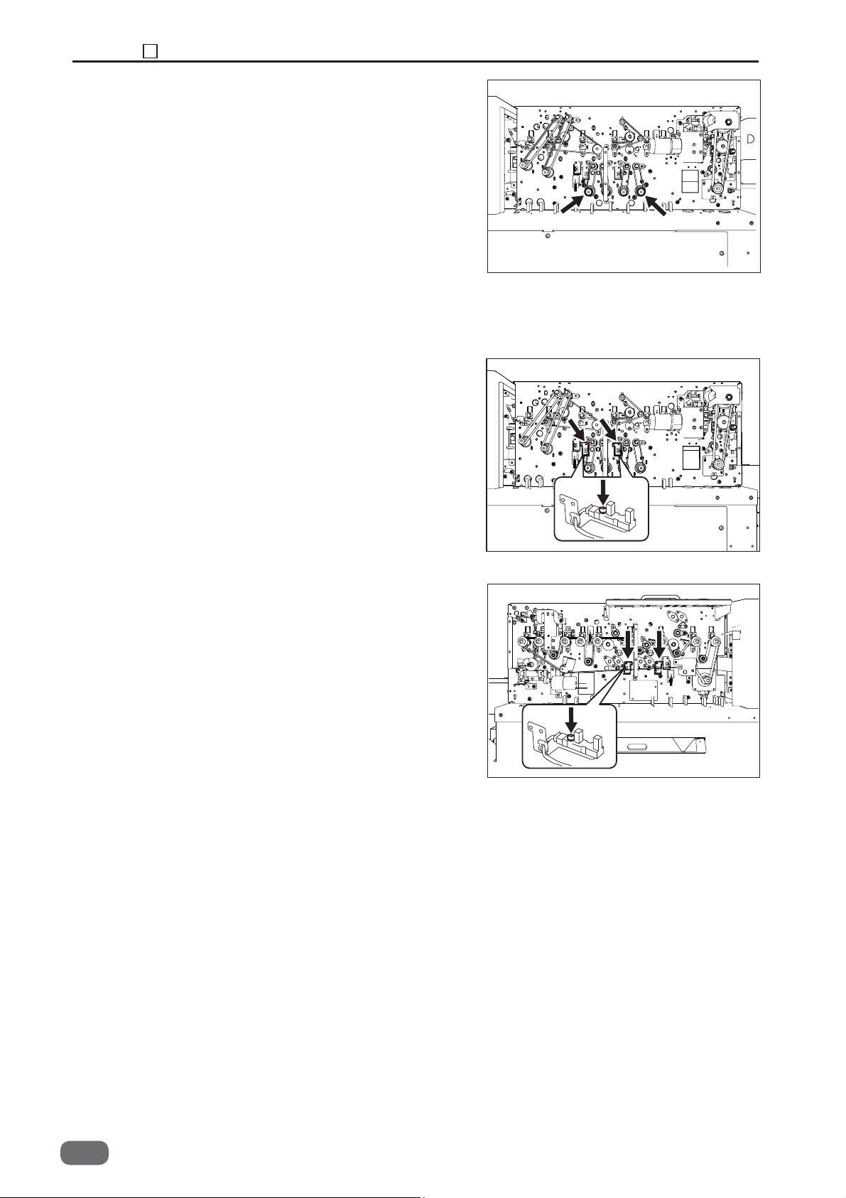
Chapter 3 6 Center Slitter Section
3. Remove the cover R.
4. Remove the timing belt.
5. Take out the four screws, and remove the motor.
* After the installation, perform the motor operation
check in HELP Mode: 31.
(See→P.53)
(HELP Mode : 31→P.149)
(3) Removing the Center Slitter Home Position Sensor
1. Remove the cover F.
(See→P.52)
2. Remove the cover R.
3. Take out one screw (each), and remove the
photointerrupter with the bracket.
4. Take out one screw (each), and remove the
photointerrupter from the bracket .
* Adjustment required at the time of installation
(See→P.53)
(See→P.104)
80
S2-Y1540
-0
Page 83

(4) Removing the PPS3
● Photo-emission sensor
1. Open the top cover.
2. Remove the cover R.
3. Take out the two screws, and remove the sensor
cover.
Chapter 3 6 Center Slitter Section
Screw
Screw
4. Take out the two screws, and remove the sensor
with the bracket.
5. Take out the screw, and remove the sensor from the
bracket.
* After installation, perform the sensor operation check
in HELP Mode: 11.
(HELP Mode : 11→P.137)
● Photo-detecting sensor
1. Take out the two screws, and remove the sensor
with the bracket.
3
Screw
2. Take out the screw, and remove the sensor from
the bracket.
* After installation, perform the sensor operation
check in HELP Mode: 11.
(HELP Mode : 11→P.137)
Screw
S2-Y1540
-0
81
Page 84

Chapter 3 6 Center Slitter Section
(5) Removing the Gutter ON/OFF Sensor
1. Remove the cover F.
2. Remove the cover R.
(See→P.52)
(See→P.53)
3. Disconnect the sensor connector.
Take out the screw, and remove the sensor with the
4.
bracket.
5. Take out the two screws , and remove the sensor.
* After the installation, perform the sensor operation
check in HELP Mode: 11.
(HELP Mode : 11→P.137)
Photo-emission sensor
Screw
Photo-detecting sensor
Screw
82
S2-Y1540
-0
Page 85

7 Cutter Section
(1) Removing the Cutter Module
1. Open the top cover.
2. Remove the covers F, R.
3. Disconnect the motor connector.
4. Take out one screw, and draw out the home
position sensor bracket.
(See→P.52) (See→P.53)
(See→P.87)
Chapter 3 7 Cutter Section
Screw
Connector
3
5. Take out the fi ve screws, and draw out the cutter
module.
* Adjustment required at the time of installation
(See→P.105)
● Removing the Slitter Blade Module
1. Take out the two screws, and remove the lock plate
unit.
Screw
Screw
Screw
Screw
Screw
Screw
Screw
2. Take out the four screws, and remove the under
guide.
* Align the top of the under guide with the top of the
blade at the time of installation.
3. Take out the three screws, and remove the bracket.
Screw
Screw
Screw
Screw
S2-Y1540
-0
83
Page 86

Chapter 3 7 Cutter Section
(2) Removing the Cutter Home Position Sensor
1. Remove the cover R.
2. Take out the two screws, and remove the sensor
with the bracket.
3. Take out one screw, and remove the sensor.
* Adjustment required at the time of installation
(See→P.53)
(See→P.107)
84
S2-Y1540
-0
Page 87

8 Creaser Section
(1) Removing the Creaser Motor and the Belt
Chapter 3 8 Creaser Section
1. Remove the covers F, R.
2. Disconnect the motor connector.
3. Loosen the motor fi xing screws, and remove the
timing belt.
4. Take out the two screws, and draw out the motor
with the bracket.
5. Take out the three screws, and remove the gear
cover and timing belt.
* Adjustment required at the time of installation
(See→P.52)
(See→P.53)
(See→P.106)
Screw
Screw
3
Connector
Screw
Screw
(2) Removing the Creaser Home Position Sensor
1. Remove the cover F.
2. Take out the two screws, and remove the photo
micro sensor with the bracket.
3. Remove the sensor from the bracket.
* Adjustment required at the time of installation
(See→P.52)
(See→P.107)
S2-Y1540
-0
85
Page 88

Chapter 3 8 Creaser Section
(3) Removing the Crease Blade
1. Remove the covers F, R.
(See→P.52)
(See→P.53)
2. Take out one screw, and remove the sensor plate.
3. Take out one screw, and remove the bearing presser.
4. Take out the three screws, and remove the gear
cover.
5. Remove the belt and the pulley unit.
Screw
Screw
Screw
Screw
Screw
6. Take out one screw, and remove the eccentric gear.
7. Take out one screw, and remove the bearing presser.
8. Draw out the eccentric shaft and the two bearings.
9. Draw out the upper blade.
10. Draw out the two springs and the lower blade.
* Apply the grease to the slider metal at the time of
installation.
* Adjustment required at the time of installation
(See→P.104)
Screw
86
S2-Y1540
-0
Page 89
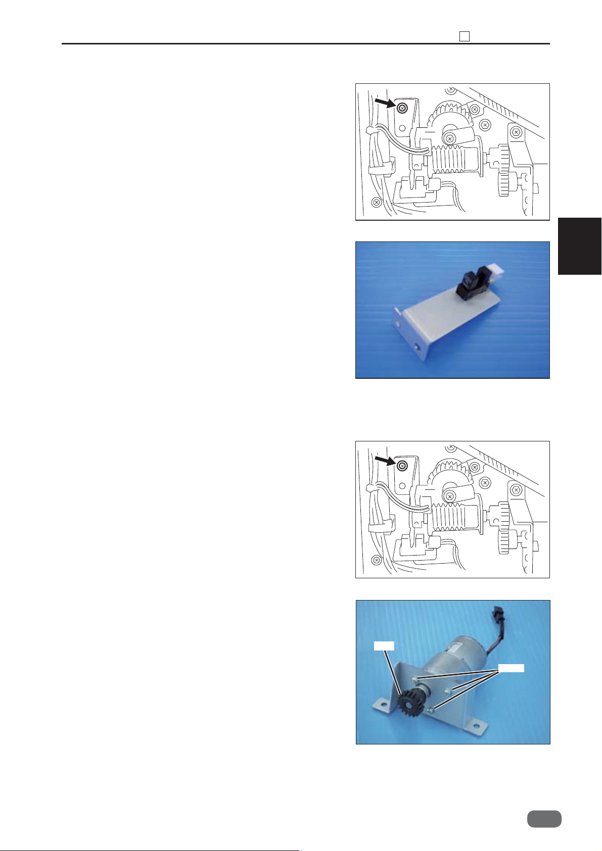
Chapter 3 8 Creaser Section
(4) Removing the Crease Lower Blade Home Position Sensor
1. Remove the cover F.
2. Take out the two screws, and remove the sensor
with the bracket.
3. Remove the sensor from the bracket.
* Adjustment required at the time of installation
(See→P.52)
(See→P.106)
3
(5) Removing the Crease Lower Blade Motor
1. Remove the cover F.
2. Take out the two screws, and remove the motor with
the bracket.
3. Loosen the hexagon socket set screw, and remove
the gear.
4. Take out the three screws, and remove the motor
from the bracket.
* Adjustment required at the time of installation
(See→P.52)
Gear
(See→P.108)
Screw
S2-Y1540
-0
87
Page 90

Chapter 3 8 Creaser Section
(6) Removing the Creaser Lower Blade Encoder Sensor
1. Remove the cover F.
(See→P.52)
2. Take out the screw, and remove the sensor with the
bracket.
3. Remove the sensor from the bracket.
* Adjustment required at the time of installation
(See→P.106)
Screw
88
S2-Y1540
-0
Page 91

(7) Removing the PPS4
● Photo-emission sensor
1. Remove the covers F, R.
2. Take out the fi ve screws, and remove the
reinforcing plate.
(See→P.52)
(See→P.53)
Chapter 3 8 Creaser Section
Screw
Screw
Screw
Screw
Screw
3. Take out one screw, and remove the sensor.
* After the installation, perform the sensor operation
check in HELP Mode: 11.
(HELP Mode : 11→P.137)
• Photo-detecting sensor
1. Take out the four screws, and remove the plate.
3
Screw
Screw
Screw
2. Take out one screw, and remove the sensor.
* After the installation, perform the sensor operation
check in HELP Mode: 11.
(HELP Mode : 11→P.137)
Screw
S2-Y1540
-0
89
Page 92

Chapter 3 9 Main Drive Section
9 Main Drive Section
(1) Removing the Main Motor and the Drive Belt
1. Remove the cover F.
2. Take out the two screws, and loosen the pulley
bracket.
3. Take out the three screws, and remove the pulley
cover.
4. Remove the timing belt.
(See→P.52)
Screw
Screw
Screw
Screw
5. Disconnect the motor connector.
Connector
90
S2-Y1540
-0
Page 93

6. Take out the four screws, and remove the motor with
bracket.
Chapter 3 9 Main Drive Section
Screw
Screw
Screw
Screw
7. Loosen the hexagon socket set screw, and remove
the gear.
* Adjustment required at the time of installation
(See→P.108)
(2) Removing the Driving Roller (Upper)
1. Remove the covers F, R.
2. Remove the bush presser spring.
3. Take out the E-ring, and remove the bush.
4. Draw out the roller from the control panel side.
(See→P.52)
(See→P.53)
Hexagon
socket set
screw
3
S2-Y1540
-0
91
Page 94

Chapter 3 9 Main Drive Section
(3) Removing the Driving Roller (Lower)
1. Remove the covers F, R.
2. Remove the two slitter driving belts.
3. Loosen the screw to remove the pulley.
4. Draw out the roller from the control panel side.
4. Loosen the timing belt.
5. Take out the screw, and remove the bearing
presser.
6. Draw out the roller.
(See→P.52)
(See→P.53)
(See→P.90)
(4) Removing the Perforation Tool
1. Take out the two black thumbscrews, and remove
the perforation unit from the DC-616.
2. Loosen the two white thumbscrews on the rear side
of the perforation unit.
REFERENCE
The white thumbscrews should be loosened only. Do
not remove them from the perforation unit.
Thumbscrew
Thumbscrew
Thumbscrew
92
S2-Y1540
-0
Page 95

Chapter 3 9 Main Drive Section
3. Loosen the two screws securing the stoppers of the
perforation tool depth adjustment screws. (approx.
3 mm)
First loosen the nut, and then loosen the screws.
4. Raise the perforation tools on both sides up to
the upper limit position with the depth adjustment
screws.
1. Loosen the nut.
2. Loosen the screw.
Depth adjustment screw
3
REFERENCE
Turn the depth adjustment screws until they stop.
REFERENCE
Make sure that the rubber roller of the upper tool is
apart from the lower tool.
If not, loosen the screws securing the stoppers in step
3 more.
Should be apart from the lower tool
S2-Y1540
-0
93
Page 96

Chapter 3 9 Main Drive Section
5. Take out the two screws of the joint securing the
shaft (upper).
6. Slide the joint in step 5 in the direction of the arrow,
and remove the shaft (upper) from the unit.
Screw
Joint
7. Replace the upper tool assy with a new one.
REFERENCE
When attaching the upper tool assy to the shaft, take
note of the orientation to attach the upper assy and
roll assy.
Loosen the hexagon socket set screws which suit the
supplied hexagon wrench size.
94
S2-Y1540
-0
Upper tool assy Roll assy
Page 97

8. Attach the shaft (upper) to the unit in the reverse
order to steps 5 and 6.
9. Move the upper tools so that the both right and left
perforation tools fi t in the grooves of the lower tools,
and move the roll assys to hold the paper.
Then lower the upper tools with the perforation
depth adjustment thumbscrews.
Chapter 3 9 Main Drive Section
Screw
3
10. When the perforation tool is raised up to the
upper limit position, adjust the screw for the upper
limit stopper to secure at the position where the
perforation tool is inside of the groove of the lower
tool.
11. Secure the perforation tool and the lower tool at
the preferred position with a hexagon socket set
screw.
12. Secure the perforation tool and the lower tool at
the preferred position with a hexagon socket set
screw.
S2-Y1540
-0
95
Page 98

Chapter 3 10 Electrical System Section
10 Electrical System Section
(1) Removing the Control Panel
WARNING
● Always remove the power cord plug from
the outlet before replacing a PCB Unit.
1. Open the top cover.
2. Remove the cover F.
3. Disconnect the connector.
4. Take out the two screw, and remove the control
panel.
5. Take out the ten screws, and remove the panel
PCB unit .
(See→P.52)
Connector
Screw
Screw
Screw
(2) Removing the Power Supply Unit
WARNING
● Always remove the power cord plug from
the outlet before replacing a PCB Unit.
1. Remove the cover.
2. Disconnect all connectors.
3. Take out the four screws, and remove the PCB unit.
* Pay attention to the terminals at the time of
installation to prevent them from touching with
each other.
96
S2-Y1540
-0
(See→P.54)
Screw
Connector
Screw
Screw
Screw
Connector
Screw
Page 99

(3) Removing the Main PCB Unit
Chapter 3 10 Electrical System Section
WARNING
● Always remove the power cord plug from
the outlet before replacing a PCB Unit.
1. Remove the cover.
(See→P.54)
2. Disconnect 10 connectors.
3. Take out the four screws, and remove the PCB unit.
* Pay attention to the terminals at the time of
installation to prevent them from touching with each
other.
(4) Removing the Drive PCB Unit
WARNING
● Always remove the power cord plug from
the outlet before replacing a PCB unit.
Screw
Connector
Screw
Screw
Connector
Connector
Screw
3
Screw
Screw
1. Remove the cover.
(See→P.54)
2. Disconnect 11 connectors.
3. Take out the six screws, and remove the drive PCB
unit.
* Pay attention to the terminals at the time of
installation to prevent them from touching with each
other.
CAUTION
Fuse: F6
● For continued protection against fi re hazard,
replace only with the same type and rating fuse.
CAUTION
Fuse: F201 - F207
● When the fuse of the drive PCB unit was
damaged, replace the drive PCB unit.
Screw
Screw
CN 5
CN 2
CN 1
CN 6 CN 10
F206
F6
F205
CN 11
F204
CN 7
Screw
Screw
F207
F202
CN 8
F201
CN 9
F203
CN 4
CN 3
F6:250V 10A
TLC10AN4
S2-Y1540
-0
97
Page 100

Chapter 3 10 Electrical System Section
(5) Removing the Main Drive PCB Unit
WARNING
● Always remove the power cord plug from
the outlet before replacing a PCB Unit.
Screw
1. Remove the cover F.
(See→P.52)
2. Disconnect three connectors.
3. Take out the two screws, and remove the PCB unit.
Screw
Connector
(6) Removing the Double Feed Detection PCB Unit
Screw
WARNING
● Always remove the power cord plug from
the outlet before replacing a PCB Unit.
1. Remove the cover R2.
(See→P.52)
2. Disconnect fi ve connectors.
3. Take out the eight screws, and remove the PCB unit.
Screw
Screw
Screw
Connector
Connector
Connector
Connector
Screw
Screw
Screw
Screw
(7) Removing the USB PCB Unit
WARNING
● Always remove the power cord plug from
the outlet before replacing a PCB Unit.
1. Remove the cover.
2. Disconnect one connector.
3. Take out the screw, and remove the PCB unit.
98
S2-Y1540
-0
(See→P.54)
Screw
Connector
Screw
Screw
 Loading...